WWW Entwicklungen Reifendruck - BorgWarner BERU Systems ...
WWW Entwicklungen Reifendruck - BorgWarner BERU Systems ...
WWW Entwicklungen Reifendruck - BorgWarner BERU Systems ...

Create successful ePaper yourself
Turn your PDF publications into a flip-book with our unique Google optimized e-Paper software.
DEVELOPMENT Tires and Wheels<br />
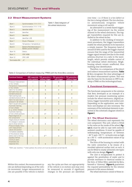
2.2 Direct Measurement <strong>Systems</strong><br />
Byte 1 Synchronisation 1111 1111<br />
Byte 2 Synchronization 1111 1110<br />
Byte 3 Identifier MSB<br />
Byte 4 Identifier<br />
Byte 5 Identifier<br />
Byte 6 Identifier LSB<br />
Byte 7 Druck / Pressure<br />
Byte 8 Temperatur / temperature<br />
Byte 9 Batterie-Restlebensdauer /<br />
Battery power indicator<br />
Byte 10 Status<br />
Byte 11 CRC MSB<br />
Byte 12 CRC LSB<br />
Termination-Bit „0˝<br />
Within this context, the measurement cycles<br />
are defined depending on of the vehicle<br />
movement. Longer measurement cycles<br />
are possible if the vehicle is station-<br />
Table 1: Data telegram of<br />
the wheel electronics<br />
Table 2: Comparison of indirect measuring TPMS with the three Beru versions<br />
Functional features ABS supported TSS generation 2 TSS generation 2 TSS generation 3<br />
series systems without trigger with trigger without trigger<br />
Pressure measurement<br />
in four wheels<br />
– + + +<br />
Temperature measurement<br />
in four wheels<br />
– + + +<br />
Alarm for tire defect<br />
Soft alarm (low sub-<br />
+ + + +<br />
standard pressure)<br />
Hard warning (sub-<br />
– + + +<br />
standard pressure 25 %)<br />
Alarm for even loss of<br />
– + + +<br />
pressure in all wheels – + + +<br />
Alarm issued with position<br />
Automatic learning<br />
of new wheels<br />
– – + +<br />
(e. g. winter wheels)<br />
Automatic learning<br />
– +* + +<br />
of new wheel positions<br />
Rapid diagnosis of<br />
– +* + +<br />
the components<br />
Target pressure transfer<br />
for changes in pressure<br />
+ + + +<br />
due to driver actions<br />
Pressure display menu<br />
with measurement<br />
+ + + +<br />
values and position<br />
Immediate availability<br />
of the pressure values<br />
– – + +<br />
before start of driving<br />
Satidfies NHTSA<br />
minimum alarm<br />
thresholds and<br />
– +** + +**<br />
response time – + + +<br />
*With user invention; **when parked, the control unit must be powered via terminal 30<br />
ary; the cycles are then cut appropriately<br />
if the vehicle is in motion and may even<br />
be measured in seconds if significant<br />
changes in the pressure are identified<br />
over time – i.e. if there is a tire defect or<br />
the tire is being inflated. The tire electronics<br />
autonomously recognizes vehicle<br />
movement using a roll switch.<br />
An alternative is a needs-based triggering<br />
of the measurement via the reverse<br />
channel to the wheel electronics. The trigger<br />
transmitters required for this are installed<br />
in the wheel arches.<br />
In addition to the clocking of measurement<br />
procedures, the trigger transmitters<br />
enable the wheel positions to be learned in<br />
a simple manner. The frequency band of<br />
around 125 kHz used for the trigger channel<br />
ensures that the range of the transmitted<br />
trigger signal remains low due to the small<br />
antenna structure in a ratio to the wavelength,<br />
which permits reliable control of<br />
the individual wheel electronics. Neighbouring<br />
wheels remain unaffected, thus<br />
enabling clear identification.<br />
Therefore, in a comparison of the direct<br />
and indirect measurement systems, Table<br />
2, Beru recognizes the clear advantages of<br />
the direct measurement system. This was<br />
also the basis for the decision in 1995 to develop<br />
a TPMS on this technological basis.<br />
3 Functional Components<br />
The functional components in the solution<br />
that Beru developed as an example of a<br />
modern tire pressure monitoring system<br />
include the wheel electronics, (digital) antenna,<br />
trigger transmitter and control unit.<br />
Depending on the application, user interfaces<br />
and displays are also necessary. The<br />
summary of the individual elements is presented<br />
in the schematic diagram shown in<br />
Figure 1.<br />
3.1 The Wheel Electronics<br />
The wheel electronics unit represents the<br />
core component. This unit, which is fitted<br />
to the valve on the inside of the wheel, Figure<br />
2, must be able to cope with extreme<br />
ambient conditions. It must be capable of<br />
withstanding temperatures of between<br />
–40°C and + 120 °C – in bursts even as high<br />
as + 150 °C – with acceleration values of up<br />
to 2,000 g.<br />
The form of the housing in contact with<br />
the valve connection is by means of a<br />
moulded spherical surface and, as such, it<br />
can be fitted to nearly all known rim types<br />
with only one design, Figure 3.<br />
The unit is encapsulated to protect it<br />
against the penetration of water and to<br />
provide resistance to chemical residue in<br />
the tires. A Teflon filter, patented by Beru,<br />
beneath a “chimney”, Figure 4, guarantees<br />
the required permeability for the interior<br />
pressure to the sensor element.<br />
The wheel electronics consist of three in-<br />
4 ATZ 2/2005 Jahrgang 107