WWW Entwicklungen Reifendruck - BorgWarner BERU Systems ...
WWW Entwicklungen Reifendruck - BorgWarner BERU Systems ...
WWW Entwicklungen Reifendruck - BorgWarner BERU Systems ...

Create successful ePaper yourself
Turn your PDF publications into a flip-book with our unique Google optimized e-Paper software.
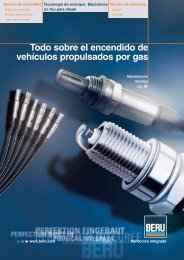
www.beru.com<br />
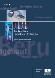
Tire Pressure Monitoring System<br />
Tire Safety System - TSS<br />
Current and Future Developments in<br />
Tire Pressure Monitoring <strong>Systems</strong><br />
Special reprint from<br />
Automobiltechnischen Zeitschrift (ATZ)<br />
Perfection<br />
built in<br />
Reprint<br />
ATZ
DEVELOPMENT Tires and Wheels<br />
Current and Future<br />
Developments<br />
in Tire Pressure<br />
Monitoring <strong>Systems</strong><br />
By Harald Bochmann,<br />
Ralf Kessler and<br />
Gunter Schulze<br />
Tire pressure monitoring systems offer more safety, greater<br />
comfort and increased efficiency. They are also increasingly in<br />
demand for high-volume cars. In principle, two different technologies<br />
are competing in this field: direct measurement and<br />
indirect measurement systems. With its Tire Safety System<br />
(TSS), Beru AG is throwing its weight behind direct measurement<br />
technology and is now presenting its third generation.<br />
2 ATZ 2/2005 Jahrgang 107
1 Introduction<br />
Tire pressure monitoring systems (TPMS)<br />
are increasingly being seen as standard features<br />
in cars. Complex insurance cases with<br />
defect tires lend added impetus to this development.<br />
For example, this issue prompted<br />
the government in the United States to<br />
introduce legislation for all cars and light<br />
commercial vehicles to be fitted with these<br />
systems in the future. The minimum requirements<br />
according to the National Highway<br />
Traffic Safety Administration (NHTSA)<br />
include the specification that an alarm be<br />
sounded if there is a 25 % loss in pressure<br />
compared to the target pressure. The reduction<br />
in pressure must be identified and displayed<br />
within no more than ten minutes<br />
[1].<br />
The speed at which the NHTSA aims to<br />
introduce these requirements is remarkable:<br />
from 1. 9. 2005 onwards, 50 % of all<br />
new vehicles are to be fitted with TPMS;<br />
this figure will rise to 90 % from 1. 9. 2006<br />
and to 100 % from 1. 9. 2007 onwards. It is<br />
not clear whether other countries will also<br />
follow, but it is fair to assume that it will be<br />
the case given the practical experience<br />
with other safety-related products.<br />
Both the government and customers<br />
alike expect systems of this kind to primarily<br />
contribute to vehicle safety. The first indications<br />
of pressure loss are indicated in<br />
advance and the driver is prompted by an<br />
alarm to replenish air in the tire or to stop<br />
the vehicle, which in most cases will prevent<br />
subsequent damage or accidents. This<br />
kind of control facility is indispensable for<br />
vehicles with run flat tires, so as to prevent<br />
the driver unknowingly proceeding with<br />
defective or insufficiently inflated tires.<br />
Over and above the safety element, drivers<br />
appreciate the benefits of tire pressure<br />
monitoring. The pressure display in the vehicle<br />
is updated at the press of a button.<br />
In view of the fact that tires are designed<br />
to last for their service life if they are properly<br />
inflated, TPMS users benefit from the<br />
increased efficiency in addition to the safety<br />
aspect.<br />
System costs have plummeted over the<br />
last few years. Accordingly, TPMS is rapidly<br />
becoming a standard feature even in midsize<br />
vehicles.<br />
2 System Variations<br />
In principle, there are two standard methods<br />
of determining tire pressure:<br />
■ Indirect measurement systems draw on<br />
measurement values provided by the ABS<br />
and/or dynamic driving systems in order to<br />
calculate changes in the tire pressure on<br />
the basis of algorithms.<br />
ATZ 2/2005 Jahrgang 107<br />
■ Direct measurement systems measure<br />
the actual pressure and temperature values<br />
of the air in the tires, which is then sent to a<br />
module for evaluation.<br />
2.1 Indirect Measurement<br />
<strong>Systems</strong><br />
Indirect measurement TPMS utilize the<br />
ABS speed sensors in the vehicles to assess<br />
differential speeds of the wheels. If the relative<br />
differential speed of one wheel suddenly<br />
exceeds a calculated threshold compared<br />
to the other wheels, the system assumes<br />
that the air pressure in the wheel in<br />
question has fallen. An alarm is then triggered.<br />
In this context, the threshold value<br />
must be aligned dynamically in order to<br />
compensate for the changes in wheel circumference<br />
due to tire wear and stress. For<br />
example, the stress differs when driving<br />
round bends or in a winter environment,<br />
in which the wheels turn at different<br />
speeds due to the differing friction. In<br />
these cases, the warning capacity of the indirect<br />
measurement TPMS is significantly<br />
restricted.<br />
Although this type of operation can be<br />
integrated cost-efficiently, such as in a<br />
software module within the ESP or ABS<br />
control units, its use is restricted to warnings<br />
in the event of a sudden drop in pressure<br />
in individual tires due to damage.<br />
However, the system will not recognize a<br />
gradual loss in pressure in all tires – for<br />
example due to diffusion – nor deviations<br />
of less than 25 % from the target value.<br />
Furthermore, it is not possible to measure<br />
the absolute pressure. Therefore, the indirect<br />
measurement systems currently on<br />
offer do not satisfy the NHTSA demands.<br />
In all probability, this applies equally<br />
to another indirect measurement TPMS<br />
version, which is currently under development.<br />
It draws on changes in the resonant<br />
frequency of the wheel/tire system<br />
depending on the tire pressure. In this<br />
system, a measurement of the rotary oscillation,<br />
which overlies the wheel rotation<br />
as interference, is used to calculate<br />
the pressure values. However, the computing<br />
of the Kalman filter used to identify<br />
the parameters is considerable and will<br />
make itself noticeable in the hardware<br />
costs [2].<br />
Accordingly, the application possibilities<br />
for indirect measurement systems are fundamentally<br />
limited.<br />
2.2 Direct Measurement<br />
<strong>Systems</strong><br />
Drawing on sensors located on the inside of<br />
the wheels, direct measurement systems<br />
determine the actual individual wheel values<br />
for pressure and temperature. The mea-<br />
The Authors<br />
Dr. Harald Bochmann,<br />
is technical director at<br />
Beru Electronics<br />
GmbH, Bretten.<br />
Ralf Kessler, is head<br />
of the product group<br />
development of tire<br />
pressure monitoring<br />
systems at Beru<br />
Electronics GmbH,<br />
Bretten.<br />
Gunter Schulze, he is<br />
head of the component<br />
development for Tire<br />
pressure monitoring<br />
systems at Beru<br />
Electronics GmbH,<br />
Bretten.<br />
sured values are sent by remote transmission<br />
together with an identification code to<br />
a control unit fitted in the vehicle [3].<br />
The pressure sensor elements generally<br />
operate on a micro-mechanical basis as<br />
part of an integrated circuit. The temperature<br />
is measured on the chip using a bandgap<br />
reference. Depending on the remote<br />
transmission conditions in the country of<br />
use, the data transmission takes place via<br />
frequency shift keying modulation (FSK) as<br />
a burst with 19 kbit/s in each case in the 433<br />
MHz or 315 MHz band. The telegram length<br />
is 96 bits, Table 1. Error protection is provided<br />
by the cyclic redundancy check algorithm<br />
(CRC).<br />
Special lithium batteries are used to<br />
power the tire electronics. Combined with<br />
the energy-optimised sensor electronics,<br />
they allow a service life of up to ten years.<br />
The required service life of the batteries<br />
can be achieved by careful circuit design<br />
and a needs-based control of the measurement<br />
cycles and transmitter activity.<br />
3
DEVELOPMENT Tires and Wheels<br />
2.2 Direct Measurement <strong>Systems</strong><br />
Byte 1 Synchronisation 1111 1111<br />
Byte 2 Synchronization 1111 1110<br />
Byte 3 Identifier MSB<br />
Byte 4 Identifier<br />
Byte 5 Identifier<br />
Byte 6 Identifier LSB<br />
Byte 7 Druck / Pressure<br />
Byte 8 Temperatur / temperature<br />
Byte 9 Batterie-Restlebensdauer /<br />
Battery power indicator<br />
Byte 10 Status<br />
Byte 11 CRC MSB<br />
Byte 12 CRC LSB<br />
Termination-Bit „0˝<br />
Within this context, the measurement cycles<br />
are defined depending on of the vehicle<br />
movement. Longer measurement cycles<br />
are possible if the vehicle is station-<br />
Table 1: Data telegram of<br />
the wheel electronics<br />
Table 2: Comparison of indirect measuring TPMS with the three Beru versions<br />
Functional features ABS supported TSS generation 2 TSS generation 2 TSS generation 3<br />
series systems without trigger with trigger without trigger<br />
Pressure measurement<br />
in four wheels<br />
– + + +<br />
Temperature measurement<br />
in four wheels<br />
– + + +<br />
Alarm for tire defect<br />
Soft alarm (low sub-<br />
+ + + +<br />
standard pressure)<br />
Hard warning (sub-<br />
– + + +<br />
standard pressure 25 %)<br />
Alarm for even loss of<br />
– + + +<br />
pressure in all wheels – + + +<br />
Alarm issued with position<br />
Automatic learning<br />
of new wheels<br />
– – + +<br />
(e. g. winter wheels)<br />
Automatic learning<br />
– +* + +<br />
of new wheel positions<br />
Rapid diagnosis of<br />
– +* + +<br />
the components<br />
Target pressure transfer<br />
for changes in pressure<br />
+ + + +<br />
due to driver actions<br />
Pressure display menu<br />
with measurement<br />
+ + + +<br />
values and position<br />
Immediate availability<br />
of the pressure values<br />
– – + +<br />
before start of driving<br />
Satidfies NHTSA<br />
minimum alarm<br />
thresholds and<br />
– +** + +**<br />
response time – + + +<br />
*With user invention; **when parked, the control unit must be powered via terminal 30<br />
ary; the cycles are then cut appropriately<br />
if the vehicle is in motion and may even<br />
be measured in seconds if significant<br />
changes in the pressure are identified<br />
over time – i.e. if there is a tire defect or<br />
the tire is being inflated. The tire electronics<br />
autonomously recognizes vehicle<br />
movement using a roll switch.<br />
An alternative is a needs-based triggering<br />
of the measurement via the reverse<br />
channel to the wheel electronics. The trigger<br />
transmitters required for this are installed<br />
in the wheel arches.<br />
In addition to the clocking of measurement<br />
procedures, the trigger transmitters<br />
enable the wheel positions to be learned in<br />
a simple manner. The frequency band of<br />
around 125 kHz used for the trigger channel<br />
ensures that the range of the transmitted<br />
trigger signal remains low due to the small<br />
antenna structure in a ratio to the wavelength,<br />
which permits reliable control of<br />
the individual wheel electronics. Neighbouring<br />
wheels remain unaffected, thus<br />
enabling clear identification.<br />
Therefore, in a comparison of the direct<br />
and indirect measurement systems, Table<br />
2, Beru recognizes the clear advantages of<br />
the direct measurement system. This was<br />
also the basis for the decision in 1995 to develop<br />
a TPMS on this technological basis.<br />
3 Functional Components<br />
The functional components in the solution<br />
that Beru developed as an example of a<br />
modern tire pressure monitoring system<br />
include the wheel electronics, (digital) antenna,<br />
trigger transmitter and control unit.<br />
Depending on the application, user interfaces<br />
and displays are also necessary. The<br />
summary of the individual elements is presented<br />
in the schematic diagram shown in<br />
Figure 1.<br />
3.1 The Wheel Electronics<br />
The wheel electronics unit represents the<br />
core component. This unit, which is fitted<br />
to the valve on the inside of the wheel, Figure<br />
2, must be able to cope with extreme<br />
ambient conditions. It must be capable of<br />
withstanding temperatures of between<br />
–40°C and + 120 °C – in bursts even as high<br />
as + 150 °C – with acceleration values of up<br />
to 2,000 g.<br />
The form of the housing in contact with<br />
the valve connection is by means of a<br />
moulded spherical surface and, as such, it<br />
can be fitted to nearly all known rim types<br />
with only one design, Figure 3.<br />
The unit is encapsulated to protect it<br />
against the penetration of water and to<br />
provide resistance to chemical residue in<br />
the tires. A Teflon filter, patented by Beru,<br />
beneath a “chimney”, Figure 4, guarantees<br />
the required permeability for the interior<br />
pressure to the sensor element.<br />
The wheel electronics consist of three in-<br />
4 ATZ 2/2005 Jahrgang 107
3 Functional Components<br />
TSS generation 2 without trigger TSS generation 2 with trigger TSS generation 3 without trigger,<br />
with compact control unit<br />
Figure 1: System description<br />
The components: wheel electronics (1), (digital) antenna (2), central control unit (3), trigger transmitter (4), compact control unit - control<br />
unit with integrated digital antenna (5)<br />
tegrated circuits. The first circuit draws on<br />
micro-mechanical structures in order to<br />
measure and digitise the values for pressure,<br />
temperature and acceleration. The value for<br />
acceleration is used as an ancillary factor. It<br />
recognizes whether the wheel is moving, so<br />
that the system can respond by switching to<br />
an aligned transmission mode.<br />
The second circuit contains a 433 MHz<br />
(or 315 MHz) transmission power stage to<br />
control the process. The transmission power<br />
is selected in such a way that the system<br />
is on the one hand suitable for certification<br />
ATZ 2/2005 Jahrgang 107<br />
under radio regulations, while on the other<br />
hand guaranteeing the greatest possible<br />
system reserves for operations.<br />
Another module wakes up the system<br />
when it receives a trigger signal of 125 kHz,<br />
thus setting it to an active mode.<br />
3.2 The Digital Antenna<br />
The digital antenna contains a 433 MHz (or<br />
315 MHz) RF receiver with corresponding demodulator<br />
and data decoder. The received<br />
measurement values are transmitted to the<br />
control unit via a LIN bus interface. The ad-<br />
vantage of this concept compared to previous<br />
systems is that no RF wiring is required<br />
in the vehicle to control the tire pressure,<br />
which considerably improves the impact of<br />
electro-mechanical interference. The receiver<br />
initially transforms the 433 MHz (or 315 MHz)<br />
signal to an intermediate frequency of 10.7<br />
MHz after preliminary filtering. This is then<br />
followed by demodulation, decoding and reformatting<br />
to the LIN protocol. The concept is<br />
designed in such a way that an adjustment<br />
of the RF circuits in series production is not<br />
necessary.<br />
5
DEVELOPMENT Tires and Wheels<br />
3.1 The Wheel Electronics<br />
Figure 3: The cross-section of the wheel electronics shows<br />
how the system can be adapted to suit various rims<br />
Figure 2: The wheel<br />
electronic system<br />
is combined with<br />
the Tire valve and<br />
installed in the rim<br />
Figure 4: Micro-mechanical pressure<br />
sensor as an integrated module – the<br />
chimney is visible on the right<br />
3.3 The Trigger Transmitter<br />
As the third component, the trigger transmitter<br />
contains the evaluation of the LIN<br />
telegram in order to control and generate<br />
the trigger data and the 125 kHz generator<br />
with a ferrite antenna as a transmission element.<br />
Both the digital antenna and the<br />
trigger transmitter are waterproof and impact-protected<br />
in a robust housing and can<br />
therefore be fitted to the outside of the vehicle<br />
without difficulty.<br />
3.4 The Control Unit<br />
The control unit processes the information<br />
received from the digital antenna and displays<br />
it on the monitor. Alarm algorithms<br />
and display strategies are implemented as<br />
a customer-specific element of the overall<br />
system. The software is based on the OSEK<br />
operating system and can be updated by<br />
Flash.<br />
3.5 The Operating and Display<br />
Unit<br />
The respective operating and display unit is<br />
coordinated with the vehicle manufacturers<br />
and is aligned to suit the interior design<br />
of the vehicle.<br />
In this, there are various versions of information.<br />
There can be a simple light control<br />
or even an alphanumerical display of<br />
the pressure and temperature values with<br />
colour-coded status of the individual wheels<br />
in the driver information system.<br />
4 Current System Concepts<br />
For reasons of installation and costs, it is<br />
more practical to fit TPMS with a central receiver<br />
unit, at least in the countries in<br />
which the radio regulations permit this.<br />
The spectrum of versions currently developed<br />
by Beru covers three variations.<br />
4.1 Basic System<br />
The basic system does not identify the<br />
wheel position, which means that it can be<br />
implemented at low cost, yet still offer immediate<br />
accumulated pressure information.<br />
An alarm is triggered as soon as insufficient<br />
tire pressure is identified, but without<br />
providing the information as to which<br />
wheel it refers to.<br />
Individual wheel position pressure display<br />
is not possible either. Individual wheel<br />
detection takes place exclusively via the<br />
identification code of the wheel electronics.<br />
However, the system alarm thresholds must<br />
either be uniform for all wheels or must on<br />
one occasion be derived from the measured<br />
pressure values in the wheel electronics using<br />
a calibration switch and then allocated<br />
to the matching identification codes of the<br />
wheel electronics. The alarm display takes<br />
6 ATZ 2/2005 Jahrgang 107
place using the driver information system<br />
without positional allocation.<br />
4.2 Trigger System<br />
If positional allocation is required in addition<br />
to the wheel electronics, the trigger system<br />
is the best technical solution compared<br />
to the other systems currently on offer.<br />
The added number of components provides<br />
fast and reliable detection of the<br />
wheel positions. The transmitter is controlled<br />
by the central control unit. A trigger<br />
signal causes the allocated wheel electronics<br />
to record a new pressure and temperature<br />
measurement value and to transmit it<br />
as a radio telegram encoded as requested<br />
information.<br />
Allocation to the wheel position is possible<br />
very quickly due to the correlation between<br />
a radio data set registered (marked)<br />
in the central receiver and the trigger request.<br />
The trigger-controlled system provides<br />
the pressure information even before<br />
the driver sets off.<br />
In this system, the target values for the<br />
tire pressures can be specified for each axle<br />
by control unit programming and can also<br />
be derived directly from the set pressures<br />
using a calibration modulator.<br />
A visual indication is given in the display,<br />
which highlights the positional information,<br />
Figure 5.<br />
4.2 Trigger System<br />
4.3 Compact System<br />
Figure 6 shows the components of the actual<br />
TSS.<br />
The latest development continues to reduce<br />
the number of system components.<br />
The Beru compact system (TSS 3rd generation)<br />
will consist only of a central receiver<br />
unit with an integrated control unit function<br />
and four wheel electronic systems.<br />
Positional allocation takes place on<br />
the basis of the rotary direction signal,<br />
which the wheel electronic systems provide<br />
in the radio data, relating the information<br />
on the direction in which the vehicle<br />
is moving, in combination with the<br />
axle-specific separation from the fitted<br />
wheel electronic systems to a comparison<br />
of the various RF reception levels.<br />
This is achieved by the installation of the<br />
central receiver unit at the front or rear of<br />
the vehicle in order to provoke these differences<br />
in the RF level. Definition of the<br />
target value for tire pressure takes place<br />
as described above. A monitor displays<br />
the warning and the positional information.<br />
5 Integration in the Vehicle<br />
Figure 5: Display in the Beru-TSS as used in the Audi A6 showing the<br />
pressure and temperature values in the individual tires<br />
ATZ 2/2005 Jahrgang 107<br />
System integration in the vehicle is divided<br />
into two areas. On the one hand, the best<br />
positions for the hardware in terms of tech-<br />
nical and design aspects must be defined,<br />
and on the other hand the system must be<br />
coupled to the vehicle wiring.<br />
5.1 Installation Space<br />
The potential installation spaces are surveyed<br />
in terms of their radio frequency reception<br />
characteristics in order to identify<br />
the best possible position for installing the<br />
receiver antenna. The most favourable position<br />
is usually in the underbody, in the<br />
bumpers or in the wheel arch. However, if<br />
the vehicle manufacturer so wishes, the antenna<br />
can also be installed in the vehicle interior.<br />
The system is fundamentally designed<br />
so that the reception of the RF signal can also<br />
be guaranteed if the tires provide considerable<br />
attenuation. Additional damping by<br />
environmental influences (snow, rain) is also<br />
considered in the system design.<br />
5.2 Networking<br />
Another factor of the system integration is<br />
the connection of the system to the vehiclespecific<br />
wiring. In most applications, the<br />
control unit is operated in the existing comfort<br />
CAN.<br />
The components of the tire pressure<br />
monitoring system all have a self-diagnosis<br />
capability. The specific manufacturer’s diagnosis<br />
services provide the required diagnosis<br />
information.<br />
The vehicle bus also deals with the operation<br />
and display of the pressure information.<br />
5.3 Technical Specifications<br />
Statutory requirements, for example the<br />
NHTSA initiative and the demands voiced<br />
by vehicle manufacturers, define the<br />
framework for alarm thresholds and response<br />
times.<br />
5.4 Special Features of the<br />
Beru TSS<br />
In addition to the tire pressure, the Beru<br />
Tire Safety System also evaluates the tire<br />
temperature. This is based on the general<br />
gas law. This temperature compensation<br />
means that the alarm threshold can be<br />
aligned with the tire pressure.<br />
A message is issued if the alarm threshold<br />
was exceeded on two successive samples.<br />
Given a typical transmission interval<br />
of one minute, this means that detection<br />
takes no longer than two minutes. If there<br />
are high changes in pressure, the wheel<br />
electronics transmit signals in cycles of<br />
merely a second. In these cases, the detection<br />
period is only two seconds.<br />
In addition to tire defects with rapid loss<br />
of pressure, the system also detects a gradual<br />
loss of pressure – for example due to dif-<br />
7
DEVELOPMENT Tires and Wheels<br />
4.3 Compact System<br />
Figure 6: Components of the Beru-TSS generation 2 without housing, with visible<br />
construction - from the left: trigger transmitter, control unit, wheel electronics,<br />
digital antenna<br />
fusion or a leaky valve. The standard<br />
threshold value for this is 0.3 bar. However,<br />
it can be varied to suit manufacturers’ requirements.<br />
This threshold is used to remind<br />
the driver as quickly as possible that a<br />
correction of the tire pressure is necessary.<br />
5.5 Examples of Applications<br />
Beru marketed its first tire pressure monitoring<br />
system in 1997 as an option for the<br />
BMW 7-Series. At the moment, the Beru<br />
TSS is currently available as a series or ad-<br />
<strong>BERU</strong> Aktiengesellschaft<br />
Mörikestrasse 155 · D-71636 Ludwigsburg<br />
P.O. Box 229 · D-71602 Ludwigsburg<br />
Phone: ++49/7141/132-693<br />
Telefax: ++49/7141/132-220<br />
www.beru.com<br />
ditional option to over 20 different models<br />
by various manufacturers. It is factory<br />
fitted as standard in top vehicles such as<br />
the Bentley Continental GT, all Ferraris,<br />
the Maybach, the Mercedes SLR and the<br />
Porsche Carrera GT.<br />
A special Beru TPMS can also be provided<br />
as an option for the heavy-duty truck<br />
from Mercedes-Benz, the Actros, with super-single<br />
tires. The Beru subsidiary company<br />
F1-<strong>Systems</strong> Ltd. has introduced TSS<br />
to motor racing and even to Formula 1.<br />
6 Outlook and Future<br />
Developments<br />
Promoted by the current legislative initiative<br />
by the NHTSA, it is fair to expect that<br />
all new vehicles in the United States will be<br />
fitted with tire pressure monitoring systems<br />
over the coming years. The automotive<br />
industry and the suppliers are working<br />
round the clock to prepare for this. As the<br />
systems have been introduced as options in<br />
the premium segment for some years now,<br />
the current development activities are targeted<br />
primarily at simplifying the installation<br />
effort in the vehicles and on achieving<br />
a high level of component integration.<br />
These measures should lead to a further cut<br />
in the system price. Various semiconductor<br />
manufacturers have already announced<br />
highly integrated modules for wheel electronic<br />
systems.<br />
A combination of the control unit functions<br />
for signal evaluation with other components<br />
in the vehicle, for example the remote<br />
locking system or the ABS system, are<br />
also possible.<br />
Technical solutions that do not require a<br />
battery for the wheel electronics are also at<br />
a preliminary development stage. Development<br />
over the next few years will show<br />
whether the familiar transponder solutions<br />
are suitable, or whether concepts that use<br />
the moving energy of the wheel electronics<br />
during the rotary phase for power<br />
generation will assert themselves.<br />
References<br />
[1] NHTSA-Richtlinie FMVSS 138. Tire Pressure<br />
Monitoring <strong>Systems</strong> (Stand 09/2004)<br />
[2] International Patent Application WO<br />
01/87647, World International Property<br />
Organization, 2001<br />
[3] Normann, N.: <strong>Reifendruck</strong>-Kontrollsystem<br />
für alle Fahrzeugklassen. In: ATZ 102<br />
(2000), Nr. 11<br />
Printed in Germany 02.03.05 Bestell- Nr. 5 000 001 069