MultiBox II - Geovent
MultiBox II - Geovent
MultiBox II - Geovent
- TAGS
- multibox
- geovent
- geovent.dk

Create successful ePaper yourself
Turn your PDF publications into a flip-book with our unique Google optimized e-Paper software.
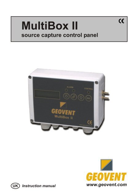
<strong>MultiBox</strong> <strong>II</strong><br />
source capture control panel<br />
UK Instruction manual<br />
www.geovent.com
Instruction Manual for <strong>MultiBox</strong> <strong>II</strong><br />
1.0 General safety precautions<br />
IMPORTANT – Please study all the<br />
instructions before mounting and<br />
commissioning.<br />
Please keep these instructions in a safe<br />
place and instruct all users in the function<br />
and operation of the product.<br />
Installation and service should only be<br />
implemented after studying the wiring<br />
diagram thoroughly.<br />
Avoid the dismantling of any factorymounted<br />
parts, since it impedes the<br />
commissioning of the equipment.<br />
All electrical installations must be carried<br />
out by an authorised electrician.<br />
1.1 Danger<br />
Dismantling parts on the <strong>MultiBox</strong> whilst<br />
in operation could be deadly dangerous.<br />
Always disconnect the <strong>MultiBox</strong> from the<br />
mains, when removing the cover.<br />
2.0 Adjustment of parameters<br />
The <strong>MultiBox</strong> contains sevaral software<br />
programs, which controls how the<br />
<strong>MultiBox</strong> behaves. The <strong>MultiBox</strong> is by<br />
default set to 530, which is the program<br />
that is to be used in 9 out of 10 situations<br />
1. Connect the <strong>MultiBox</strong> to 230 Volts<br />
as shown in the diagram<br />
2. The Display will show “P0” on<br />
power-up<br />
3. Press “ENTER” and select the<br />
appropriate software program by<br />
scrolling with the “+” and “-“ keys<br />
and the press “ENTER” once<br />
more.<br />
4. Shift to P1 (the set point<br />
parameter) by using the “+” key<br />
and the press “ENTER” – adjust<br />
the value to your desired set point<br />
pressure (in Pascals) and press<br />
“ENTER” once more.<br />
5. Use the “+” until you get to P10.<br />
6. Keep the “ENTER” key pressed<br />
until you get a beep (tells you that<br />
the changes you have made are<br />
now saved in EEPROM).<br />
7. In case of failure – cut the power<br />
for at least 20 seconds and put it<br />
back on. The <strong>MultiBox</strong> is now reset<br />
and you must start the<br />
programming procedure again.<br />
Table of general FV56X parameters<br />
P92 Start 0 0-1-2 0=closed,<br />
position<br />
1=open, 2=freese<br />
P93 Zero Nej Ja Calibration of<br />
calibration<br />
pressure zero<br />
(Pa)<br />
P94 Manual Ja Yes- Yes=Manual<br />
start/stop No start; No=Auto<br />
P95 Alarm delay 10 3600 Time delay before<br />
alarm signal<br />
P96 Language DK GB Chose DK or GB<br />
choice<br />
language<br />
P97 Disable<br />
sound<br />
0 0-1 Disable alarm sound<br />
when P97=1<br />
P98 PIN-code 0 8888<br />
P99 Parameter<br />
Reset<br />
P00 Choose of<br />
version<br />
PIN-code for parameter<br />
adjustment<br />
No Yes Yes = Reset all<br />
parameters<br />
550 Table Software version<br />
1 selection<br />
05-06-2008 ver. 2.2 www.geovent.com Side 1/4
Instruction Manual for <strong>MultiBox</strong> <strong>II</strong><br />
The software is applied for PID feedback<br />
regulation of process air extraction by<br />
means of frequency inverter or electric or<br />
pneumatic damper. The regulator PID<br />
signal can be inverted, and thereby have<br />
opposite direction. The Transmitter has<br />
0-10V signal for calculated air extraction<br />
flow, and slave control of balanced Inlet<br />
air.<br />
The following start-up procedure is<br />
recommended:<br />
• Installation according to diagram<br />
below<br />
• Green or Red Alarm diode when T3 is<br />
active<br />
• Select software V530 or V630 in<br />
Parameter P00<br />
• Connect one pressure sensor tube to<br />
ventilation ducting, or 2 sensor tubes<br />
to a flow meter<br />
• Select desired regulator setpoint (Pa)<br />
in P01<br />
• Select min. and max. alarm limits in<br />
P02 and P03<br />
• Control signal in T10 can be inverted<br />
in P16.<br />
• Terminal T10 is connected to freq. inv.<br />
or damper<br />
• Terminal T8 with slave signal for<br />
balanced inlet air is connected to inlet<br />
air frequency inverter<br />
• Terminal T9 with flow signal (l/s) can<br />
be connected to Sumbox such as<br />
version V670 or V675.<br />
• Max fan capacity (50 Hz) is entered<br />
into P14<br />
• Controller start in T4 or pres ESC<br />
(when P94=yes).<br />
After start-up the following adjustments<br />
are possible:<br />
• Adjust PID regulator: higher P06-value<br />
will speed up the regulator, and higher<br />
P07-value will moderate the regulator<br />
and reduce instability<br />
• Adjust P22 and P23 to max Room and<br />
Inlet air flow<br />
• T8 has 0-10V signal for Inlet air slave<br />
control<br />
• T9 has 0-10V signal for flow rate<br />
transmitter<br />
The regulator maintains the actual set<br />
point as indicated in P10, and transmit<br />
0-10V signals for flow rate(T9) and<br />
slave control of Inlet air (T8) with<br />
frequency control.<br />
05-06-2008 ver. 2.2 www.geovent.com Side 2/4
Instruction Manual for <strong>MultiBox</strong> <strong>II</strong><br />
5.0 PARAMETER LIST<br />
Par. Label Def. Max Def Max Description<br />
P00 Model number 530 530 630 630 Software version number<br />
P01 Setpoint+pressure 1000 5000 100 1000 Adjust PID setpoint + pressure<br />
P02 Min. alarm limit<br />
(Pa)<br />
200 4999 20 999 Monitor alarm min. limit (Pa)<br />
P03 Max. alarm limit 5000 5000 1000 1000 Monitor alarm max. limit (Pa)<br />
5.0 Wiring for Multibox<br />
Power supply<br />
N<br />
230 V<br />
L<br />
(Pa)<br />
P04 Time delay (sec) 10 3600 10 3600 Time delay to shut down<br />
P05 Neutral zone (Pa) 3 1000 3 1000 Neutral zone from set point<br />
P06 P-factor (PID) 3 200 3 200 Regulator P-factor (speed)<br />
P07 I-time (PID) (sec) 3 1000 3 1000 Regulator I-time (moderation)<br />
D10 Pressure+setpoint 0 5000 0 1000 Actual press.+setpoint values<br />
P14 Max flow for T10 1000 9999 1000 9999 Max capacity (l/s) main fan<br />
P16 Invert PID signal No Yes No Yes No = normal PID ; Yes = invert<br />
D18 Flow display (l/s) 0 - 0 - Flow with K-factor in P17<br />
P22 Max Room flow 1 9999 1 9999 Room fan max capacity (l/s)<br />
P23 Max Inlet flow 1000 9999 1000 9999 Inlet fan max capacity (l/s)<br />
P24 Residual flow 0 9999 0 9999 Residual fan max capacity<br />
D49 Display T10 (V) 0 - 0 - 0-10V value from PID (V)<br />
D50 Display T9 (V) 0 - 0 - 10-0V Room air value (V)<br />
D51 Display T8 (V) 0 - 0 - 0-10V Inlet air value (V)<br />
P52 Min. limit T10 (V) 0 9 0 9 Adjust voltage limit for T10<br />
P53 Max. limit T10 (V) 10 1 10 1 Adjust voltage limit for T10<br />
P54 Min Limit T9 (V) 0 9 0 9 Adjust voltage limit for T9<br />
P55 Max limit T9 (V) 10 1 10 1 Adjust voltage limit for T9<br />
P56 Min Limit T8 (V) 0 9 0 9 Adjust voltage limit for T8<br />
P57 Max limit T8 (V) 10 1 10 1 Adjust voltage limit for T8<br />
P73 Flow rate (10V) 1000 9999 1000 9999 Flow (l/s) limit T9 at 10V output<br />
P92 Start position 0 0-1-2 0 0-1-2 0=closed; 1=open; 2=freeze<br />
P93 Zero calibration No Yes No Yes Calibration of pressure zero<br />
P94 Manual start (ESC) Yes No Yes No No = auto start; Yes = manual<br />
P97 Disable alarm<br />
sound<br />
0 0-1 0 0-1 Disable sound when P97=1<br />
230V<br />
Voltage-free contacts<br />
Installation diagram for software version V530 and V630<br />
Start/stop Voltage<br />
Control<br />
Alarm<br />
Transmitters 0-10V<br />
CTS Alarm Light Motor T4 T3 T11 T12 T13 5V 24V PIR T10 T9 T8 T7 T6 T5<br />
NC C NO NC C NO 24V0 + 0 + 0 + 0 + 24V 0 + 24V 0 + 24V 0<br />
Control<br />
start/<br />
stop<br />
Alarm<br />
start/<br />
stop<br />
Controller and Regulator outputs<br />
05-06-2008 ver. 2.2 www.geovent.com Side 2/4<br />
Control<br />
0-10V<br />
signal<br />
Flow<br />
rate (l/s)<br />
signal<br />
Inlet air<br />
slave<br />
signal<br />
Alarm<br />
signal<br />
Control<br />
pulse<br />
signal<br />
Control<br />
pulse<br />
signal
Instruction Manual for <strong>MultiBox</strong> <strong>II</strong><br />
6.0 Liability<br />
Warranty<br />
<strong>Geovent</strong> A/S grants a warranty for products, which<br />
are defective; when it can be proved that the<br />
defects are due to poor manufacture or materials<br />
on the part of <strong>Geovent</strong>. The warranty comprises<br />
remedial action (reparation or exchange) until one<br />
year after date of shipment. No claims can be<br />
made against <strong>Geovent</strong> A/S in relation to loss of<br />
earnings or consequential loss as a result of<br />
defects on products from <strong>Geovent</strong>.<br />
User liability<br />
In order for <strong>Geovent</strong> to be capable of granting the<br />
declared warranty, the user/fitter must follow this<br />
Instruction Manual in all respects.<br />
Under no circumstances may the products be<br />
changed in any way, without prior written<br />
agreement with <strong>Geovent</strong> A/S.<br />
7.0 Declaration of conformity<br />
The manufacturer: GEOVENT A/S<br />
HOVEDGADEN 86<br />
DK-8831 LØGSTRUP<br />
hereby declares that:<br />
The product: <strong>MultiBox</strong> <strong>II</strong><br />
has been manufactured in compliance with the<br />
directions of the Directive Council of 14 June<br />
1989 in common approximation to the legislation<br />
of the member states regarding machine safety<br />
(89/392/EEC amended by the directive<br />
91/368/EEC) with special reference to appendix 1<br />
in the Directive regarding basic health and safety<br />
requirements in connection with the construction<br />
and manufacturing of machinery.<br />
GEOVENT A/S • HOVEDGADEN 86 • DK-8831<br />
LØGSTRUP<br />
Position: Managing Director<br />
Name: Steen Molsen<br />
Date: 05/06/2008<br />
Signature: ____________________________<br />
05-06-2008 ver. 2.2 www.geovent.com Side 1/4