sinamics g120 - Meyer Industrie Electronic
sinamics g120 - Meyer Industrie Electronic
sinamics g120 - Meyer Industrie Electronic

You also want an ePaper? Increase the reach of your titles
YUMPU automatically turns print PDFs into web optimized ePapers that Google loves.
■ Technical specifications<br />
© Siemens AG 2007<br />
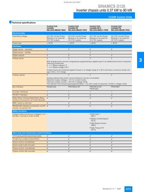
SINAMICS G120<br />
Inverter chassis units 0.37 kW to 90 kW<br />
CU240 Control Units<br />
Control Unit<br />
Control Unit<br />
Control Unit<br />
Control Unit<br />
CU240S<br />
CU240S DP<br />
CU240S DP-F<br />
CU240S PN<br />
6SL3244-0BA20-1BA0 6SL3244-0BA20-1PA0 6SL3244-0BA21-1PA0 6SL3244-0BA20-1FA0<br />
Electrical data<br />
Operating voltage 24 V DC via the Power 24 V DC via the Power 24 V DC via the Power 24 V DC via the Power<br />
Module or an external Module or an external Module or an external Module or an external<br />
24 V DC supply 24 V DC supply 24 V DC supply 24 V DC supply<br />
Power loss<br />
Interfaces<br />
< 40 W < 40 W < 40 W < 40 W<br />
Digital inputs – standard 9 9 6 9<br />
Digital inputs – failsafe – – 2 –<br />
Digital outputs 3 3 3 3<br />
Analog inputs 2 2 2 2<br />
Both analog inputs can be configured as supplementary digital inputs if an additional function is required.<br />
Switching thresholds:<br />
0 → 1: Rated voltage 2 V<br />
1 → 0: Rated voltage 0.8 V<br />
Analog inputs are protected against inputs in a voltage range of ± 30 V and have a common-mode voltage<br />
in the ± 15 V range.<br />
Analog outputs 2 2 2 2<br />
Analog outputs have short-circuit protection, but are not isolated.<br />
Maximum output voltage = 10 V in current mode,<br />
maximum output current = 20 mA in voltage mode.<br />
The reaction time should equal approximately 1 ms with a load of maximum 10 kΩ in voltage mode.<br />
Bus interface RS485/USS PROFIBUS DP PROFIBUS DP,<br />
PROFIsafe<br />
PROFINET<br />
Encoder interfaces 1 1 1 1<br />
PTC/KTY interface ✓ ✓ ✓ ✓<br />
Brake Relay interface/Safe Brake Relay<br />
interface (connection via Power Module)<br />
✓ ✓ ✓ ✓<br />
MMC memory card slot ✓ ✓ ✓ ✓<br />
RS232/USS interface (connection via PC<br />
inverter connection kit)<br />
Safety functions<br />
✓ ✓ ✓ ✓<br />
Integral safety functions to Category 3 of – – Safe Stop 1<br />
–<br />
EN 954-1 and SIL2 of IEC 61508<br />
(SS1)<br />
Safely Limited Speed<br />
(SLS)<br />
Safe Brake Control<br />
(SBC)<br />
Safe Torque Off<br />
(STO)<br />
Open-loop and closed-loop control functions<br />
V/f linear/quadratic/parameterizable ✓ ✓ ✓ ✓<br />
V/f with flux current control (FCC) ✓ ✓ ✓ ✓<br />
Vector control, encoderless ✓ ✓ ✓ ✓<br />
Vector control with encoder ✓ ✓ ✓ ✓<br />
Torque control, encoderless ✓ ✓ ✓ ✓<br />
Torque control with encoder ✓ ✓ ✓ ✓<br />
Siemens D 11.1 · 2007<br />
3/13<br />
3