P E. Process Flow and Control Diagrams - Fischer-Tropsch Archive
P E. Process Flow and Control Diagrams - Fischer-Tropsch Archive
P E. Process Flow and Control Diagrams - Fischer-Tropsch Archive

You also want an ePaper? Increase the reach of your titles
YUMPU automatically turns print PDFs into web optimized ePapers that Google loves.
°<br />
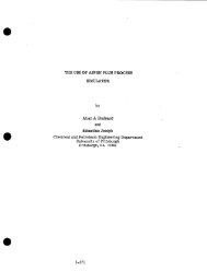
E. <strong>Process</strong> <strong>Flow</strong> <strong>and</strong> <strong>Control</strong> <strong>Diagrams</strong> (ZncludlngMaterlal<br />
Balance)<br />
Unit 32 are as follc~s:<br />
<strong>Process</strong> <strong>Flow</strong> <strong>and</strong> <strong>Control</strong> <strong>Diagrams</strong> for Gas Fractioaation<br />
Drawlu~,NOo Title<br />
D-32-MP-1NP<br />
~-32-MP-2NP<br />
D-32-MP-3NP<br />
D-32-MP-4NP<br />
D-32-MP-SNP<br />
PFCD Gas Fractiouat$on - Depentaulzatlon<br />
PFCD Gas Fractlouatlon - Depentanlzatlon<br />
PFCD Gas Fractionatlon - Gasollne Splitting<br />
PFCD Gas Practlonation - Depropanlzatlon<br />
Material Balance - Gas Fractlonatlon<br />
II-I .2 ° 13-12
A<br />
C<br />
D<br />
, I 2 I = I 4,+<br />
ii iiiii m +<br />
3Z-01-2001 32-01-13~tl 32-01-1 I01 32-01-1301 32-01-130~ ~2-01-1303<br />
GAS FIf ACTIORATIOH AnsOABF.fl OEETImHIZER ABSORnER DEETHAH~ZEA AOSOflg~IAHr'Lt ",rl AOSORB~ 9EETHA--HrZER ABSCfl'~n~ZEA<br />
ItEFIIIG,~flATXOI4 IpACIfAIiE Slg( P,I[OOILEli ' -- A ~ " CHILLER R£OOtLER ~<br />
3, I UUUTtJ/Im 5,S mOlWlll~ 3~a umTU/m 3. I UeO1U/HA O3,~'-~HII<br />
32-01-2001<br />
]<br />
--I P"A-32<br />
/ kMIIO~LVREFRIG£AkTIdH<br />
/ 3~A'32<br />
__JAMMOMLAIAEFR|OEItATIOM<br />
. ~ 4"~U;,-32<br />
SEPARATOR DRUM<br />
I n-31'llP..I I
'+<br />
,~ ~ ~I ,, ~ ~ ~, ~,: ~.;~ ~1,~ ~.~ ~ ~'~'l, ,~.<br />
3Z-0t-I203 32-af-t204<br />
~z--~i ~ ~osoeeu O(~r~NZZEn =XTF~Onm<br />
IfAT[R D~IAil OItUHS ~ CORTACT DRUM ' "<br />
I<br />
0l'13Q~ DO HOT POCKET<br />
-oi-j_i<br />
ll( 2-_____.~2<br />
IOH~FF<br />
¢~ I~B "32<br />
32-01-1501<br />
]Z-Ol-15O2<br />
FIGURE 4-2<br />
I<br />
,,,(.,C.ga[<br />
HJC. ,.H.F.<br />
I<br />
t<br />
I <<br />
SET S<br />
_:._~ I T4 PS|O<br />
32~f-f203<br />
FZGUilE 2-4<br />
-1--<br />
KOTE 2<br />
NOTE~<br />
I. Tile F~UIPkEHT SttOWN OH tHIS DRAW][HO IS FOR<br />
ONE 1RAIH. THE PLANT WILL CONTAIN OHLY<br />
• E NOTE 3<br />
OIR TKAIH,<br />
2, lOyAL LIGIIT IITgROCARBOI~ AVDL4G( MOLECUI,~R<br />
IIUOIIT • 44.0<br />
3, UEIllAKOL IS AOD~ AS REQUIRED TO %HHIOJT<br />
HYDRATE FORMATXON, METHAHOL 15 HOTFl~QUIREU<br />
FOR H~P, IkL 0P(flATIQR<br />
!"-AA-]Z ~,, ......<br />
FUEL 6AS/HF.AO~A ~<br />
4. THE nGUR~ ltUMQ(l~ REFER TO TIlE TYPYJ~L<br />
EQUIPU(NT COItFIGURAl%OH$ SHaH OH DRAWING<br />
O-OI~-~.<br />
L.P. FLARE ~ I[--1<br />
' HE<br />
- 1'-~'32 / ~ -- H.N.F.<br />
- -I F FROM DEPEHTANIZTz, R<br />
3Z'-O I- 1204 ~ ~ RETLUX DRUM<br />
It~,R.]2.! FIGURE 2-2<br />
150 PSIG 5TEAR ~ li~<br />
¢ONDEI(SATE ~ WASTE WATER<br />
DEETIL~HIZI~R BOTTOMS/ DEPEHTANIZ[R<br />
LEAN OIL/ LEAR OIL P5~<br />
(OLII~EHT ~ 0;4 IH~ 0~II%~<br />
3~"01-1S01<br />
~-01-'~<br />
32-01-1101<br />
]Z-Ol-12Ol<br />
32-01-1202<br />
32-01-1203<br />
3Z-01-1204<br />
]2 "Ol'l'qOI<br />
32.,,01*1]02<br />
9"01-1501<br />
)2-01-150Z<br />
32-01-Z801<br />
3n ,.r. - U,S. DEP~TI'ENT OF ENERGY<br />
~, COAL- TO- METHPNOL- TO" GASOLINE PLPJqT I~<br />
~s ~]o~no~ - "at 3;= ~='="'~-32-MP- I NP<br />
D
'-XA-ll<br />
I 0,,:: "" t il' ), lull. GAS ItEADII<br />
, I, l I 3 I<br />
ll-01-1102 ~ 31-01-1]05<br />
,~[IITANIIEII pEPEIIllllllll I All I ClLEn O~lt 3l'01 ' '"~<br />
l~ PSiO<br />
11,4 lllOlLl# illl~<br />
llll, I--<br />
L.P; FlAil( ,.m-r-1 )_2_"91-I14D- ~ i<br />
20',-AA-)9-1,<br />
i ' -<br />
..... _ ..--, ~:-m,, 4~<br />
. I_a<br />
39-01-110l<br />
..... . I'-'B-31 ~.IL F, I1,1 F,<br />
~1i-32-11~1 lip u lATER# IIIOCI~I DRill I '~ 14"-AA-32-I<br />
i "<br />
- _ lll'-IA-31"-I<br />
o i o.~,.,,.., .__ ,,,..~.~. i ~ ~ , .....................<br />
c_Lm, 4~ -"<br />
~_l~32-.liP-I t " 4"-AA-3i-1<br />
' LEAN OllJAOIER ~ :~::~ 32-01 --<br />
32""01-1503 32"01-15~1<br />
,s2.01.150 l<br />
FICUII( 4-Z. FIGtII~ 4-Z<br />
32-01-150._....__~3 3201-1505 32-01-1507 ..<br />
32"0U-1504 31-01-150@ 32"0101501 ~.;<br />
,LEAN OIL PLIMP All) SPARE ,D~ENTAI~z~t OO'ITOM5 DEPEliTANIZI[R REFLUX, "'""<br />
T5 H,P. PLO~ AllO 5PARE ptAil AlE) 5PAItE ;~,,,"<br />
40 ILl'. 50 ILP,<br />
t!i. I<br />
Ill pl,/,,k,i I i~lll_@l<br />
~1 I I I~ nlrno~l I IpL4d i'll I "<br />
I!,;, , /11 I I . __ I'l it' o'-",°'''"'"<br />
AI.r,.,,.i I liud r.'cl [ "<br />
' "' "'"-"-<br />
1 I i I ~ I -<br />
- o<br />
p<br />
i<br />
~
J" -<br />
4~ ~ , t ,,, o I 7<br />
., , ~ ~-o,-,~,,<br />
SET •<br />
:'. ..... -"i L<br />
I<br />
I<br />
I<br />
I<br />
31-01-1501 3Z-01=IS0~i<br />
]~-01-15011 3~.-01=15i0<br />
FIGUR~ 4-2 F[OI~E 4-2<br />
ii.m<br />
maT~,n '<br />
--' ' ~ i l l i l l l ~ I I l i l l l l l r i l l i l i l ~<br />
I I<br />
I I<br />
I TO PARkLUEL<br />
r'~B.-32 I I~IDIOlO..£R<br />
I 32'.,01= I ~ID~O<br />
i~.<br />
•<br />
I 12"R-~.-i<br />
I 150 PSl6~rdLil ~-~I~<br />
3%"01-13~k<br />
3Z"01-130~8<br />
I<br />
1<br />
FICHE 3..4 I<br />
. ~ 4'=~'32-I<br />
COr~EX~TE ~ ~-~<br />
32~f-I$~<br />
3Z'Ol-I~l 0<br />
•- f~ ~s~ ~IT :[',.m,. I<br />
• ! rm atreT ~PeOVA~. i "~-,,,.- ; ecx ll~,~ail<br />
• I FOR S~ I~I'FNT k[vz~.q l l "" " --- I ec h~/~?|<br />
": ..... : ~,:',-- I~..~..w.. , r~ I,~,L~ U W. ~ C ~<br />
~o<br />
m<br />
~'-~-1" ~-£;.-~.;.~,<br />
~-~-3~-1<br />
~TESl<br />
Z, VJU~q 4~ ¢llOL[I<br />
V&/~il ~ IMOL[I<br />
YAPOfl iIOLECULC.q ~T • iS, 4<br />
[0U~IRI~' $H0m ~ TIRS oRum~<br />
32'-01-1102 32-01-1503<br />
32.'01-1205 3~1-1504<br />
]2.'01-1304 3Z'Ol°iSa5<br />
32-01-1~5 ]Z-OI-ISOG<br />
32-01-13QG 3Z~l-I~/<br />
3Z*01-1315 32-01-1S08<br />
]Z"Ol-lSlO<br />
• U.S.0EPP.~THENT 0~: ~ ,<br />
I .~=r, w~i;i~mcE i co.<br />
I ~ ~"<br />
L. co~-'ro- ,~'r,,,~. - so- ~.so,.~ ~ _ ,~<br />
A<br />
7..<br />
D<br />
i
A<br />
,,p<br />
C<br />
D<br />
" G"'AA-bt<br />
, I " I = i 40,<br />
8'-~U~-32-1<br />
L D-"-Z-.MP-2 ~ O~HTANXZF~R BOTTOI~<br />
DEPEHTANIZER EXCHANGER<br />
4P-AA-32-Z<br />
~9-6'~-MP-I UP ~ ARCCA,~TZC XYOROCARBONS/STGPJkG( ~..~.<br />
J °<br />
I<br />
'q2-01-1307 32-01-1103 3Z-01-13011 3Z-01-1320<br />
SPL'IT]'I~ BOTTOi4S G~SOI.INE .SPLITIER 01SOLI~ sPLrri'£R GA~-------~'~-"IT~<br />
-- AIR COOLER ' AIR G'IOL~ FEF-o/OVERH~eo<br />
10.5 1~61U/XR 62.2 li4JTU/XR<br />
S"AA-32-!<br />
'~2-Ot-I30T<br />
F~GURr 4- I<br />
I ' ' I • I<br />
-- {I<br />
liOTE 4"-" '~ IG~<br />
(HDTE 2)<br />
4"A~-32-Z<br />
SET •<br />
2O PSXG I~ r I0'<br />
32-01-1320A<br />
.. FIGURE 3-~<br />
L !<br />
"-~--~--1 I<br />
._ t_~_..~<br />
FLC:I<br />
32-01-1103<br />
FZGURE I-I<br />
32-01-1513 32,'-01-151 '~<br />
32-01-1514 32-'01-i516<br />
F'/GLI~[ 4-2 I~GURE 4-2<br />
.je<br />
24"-k~-32-I<br />
6"-'kk-32-X<br />
32"01-1308A<br />
Z<br />
?<br />
(m,, m~. .......<br />
m<br />
.....<br />
IO'-AA-37<br />
32-01-1513 3~-01-1SI5 ._.. :<br />
3Z-01-1514 32--01-1516<br />
GASOLINE SPL2'rTER GA'~,ot.mr SPLX'TI"ER GASO~"-" .... :<br />
IO X.P. 200 H.P. !.,~ u P<br />
3<br />
~, c ~,I.,J,~ ~ ,v~. ~ :~-,Y~//~" .....<br />
- B I v~ p.i.~ F,£<br />
A ,v,w, ~I FJC<br />
No,~.~vtlev 34a)r,r.c mo~ ~J~<br />
~'-'~ ".-.. ;~
• '-"~<br />
~...L"<br />
%)'01-1517<br />
~,,-,..~,,,~'~,~. '/.~F~!~!~;~;`~`~'~.r~'~'/'~}`~`~C~`.~i~;~¢~:,~:~!~!{~`~;~z~" i!~'~Z, ','~'.' ~,, .,.. ,,<br />
El~O ' REFLUX I)flUil AIR COOL~<br />
. . ~ t£~'~n<br />
DO HOT<br />
q<br />
32"-01-151T<br />
32-01-1310<br />
I<br />
I<br />
- -': ~:;~, ;'P, OOUCT/<br />
I00 H,p.<br />
I)<br />
T _<br />
"1<br />
I<br />
I<br />
I<br />
32"01-1206<br />
~GUR( 2-'4<br />
32'01-1311<br />
"FZGURE 3-t<br />
32-01-130~Jk t<br />
32"01-13058 I<br />
W.<br />
SET •<br />
,~20 PSIG<br />
4"P G' I~<br />
L.P. FLARF.~---<br />
I . I r--R-32-I<br />
I I;00 PSIG STEAM" I r-I<br />
4'*1~-32-1<br />
®<br />
! -- 5 - ~ "<br />
11"'~-32<br />
fUEL 0,5 ,~<br />
8"-AA-32-I<br />
LIGI~ GASOLINU STY[<br />
P-Bk-3~-I<br />
#,ROiikTIO XYOROCAi~OILY STOAkGE<br />
4~DA'32-1<br />
AROMATIC X Y O ~ i~l'<br />
NOTEs1<br />
h THE [~J~'M(NT SHOIlM ON TILLS DRklINO 15 roA<br />
~I~ILRAIN, Ill PLANT Wg.L CONTAIN ONLY OH(<br />
7<br />
, ,.,,,,<br />
~, DLI~NG HOT LJ~T REGEIIERAYIOI~ A 14 DAY Pf..RIOR,<br />
u~.lJl[ PLIIEN BOTTOMS |5 SENT TO S'IORAG(<br />
ov ~Tcmw; com~ wv(5 A~o ,~c.vATIwo<br />
!~',~ ~mre .on~ me ,z to<br />
r ~.IIT[~ BOTTORS To 5TODAGE, A<br />
3, O~|WG NOT UNIT OPEI~TIOH, 'rill{ DASOLI.N(<br />
SPLITTER BOTTOMS 5TOAAG( PUWP IS OPEI~TEO<br />
OR A |ill DAY P(R[OO TO PROVIDE ."HE ADGEO<br />
EEO AEOU~9£O TO 'THE HGT UNIT TO ME(T 1HE<br />
XTO PLANT STREMI DAY FACTOR 0~" 9~, THE XOT<br />
IJHl'f MrdtAllOl~ 15 BASED OH A 5TREAM DAY<br />
FACION Of 8~¢. GASOLDiE SPLITTER BOTTOUS<br />
PUMP *1 IS ALSO OPF.~TEO OU~HO HGT UNIT<br />
OPEJUT[QN.<br />
4, VAPOR 3(¢ (MOt.()<br />
VAPOR WOL(~L~ IElb'Hl, 54.6<br />
5, THE FLOUR( IOJUB~S REFER TO THE TTPICAL<br />
EOUIPiI(IIT COIfI~T!ONS SHOWN ON DP,,klIN3<br />
0-01.'~-2,<br />
~NT SHORN 01 T~S D~YIHG~<br />
3~-0 I-I I(~ 3Z-OI-ISI3<br />
32-01-120G 3Z-01-1514<br />
32,4}1-130T ~1-1SI5<br />
32-G1-1308 32-0l-t51S<br />
3Z-DI-1309 ~-4)I-ISIT<br />
3Z-01-1310 ~'01-1518<br />
3Z-01-1311<br />
)~J~. IE.A 3Z~1-1320<br />
U.S, DEPP.RTHENT OF ENERGY<br />
V.q.G~ & CO,<br />
Be,me B.P.B. ......<br />
- TO - METHANOL " TO - GASOLINE PLANT II<br />
lm
A<br />
c<br />
' ~ I"AA-'~!<br />
[ ,-~z-~-z ,e)s'-~-3z IIEPEXTANIZF.A PROOUCT/<br />
DEPEIITAHIZ~ REFLUX DI1UU<br />
If'L:'<br />
i AWINQ<br />
O,G¢.Zi lllJYsl<br />
DISCII IPTION<br />
1 I°1<br />
, 4U,<br />
32-01-1313 32"01"1311 32-01-1 IOI<br />
D_~HR(R ~,LKI'LAIIOH FEED _ ALKYLA'-"TIOH FEED . ~ DEPIIOPA~-'(R ~ ~ 32-01-1]14<br />
rf'~ / ~.1"~1~ B(CIIAHG[I1, ALl ctxx, r~ IkTEll COOLER ._R~EFLIJX CONOE~EII<br />
I;,O ili6TLVI~ 5,5 llglW~ hE 14JOTWIHI<br />
32-01-1312<br />
F[OURE 3-I<br />
k"T I 2~0 PSIO<br />
6"0 I0' LP FL4RJ~ -II-'-I<br />
3Z-I)l-I IOq .4<br />
ncunE I-..__....~<br />
!,r I,<br />
I 2 I<br />
I<br />
1<br />
8"'~-32<br />
"-~i ~ I ~-AA-32-!<br />
_ I 0"'~-32-|<br />
T<br />
I<br />
-[~<br />
gE~'DllrrlOH<br />
3<br />
8'.-~-32-!<br />
12".-AA-32-!<br />
32"-01-1'~19<br />
32"01-1520<br />
FIGURE 4-2<br />
4"-'AA-32<br />
]2-01-1519<br />
32-01-15:'0<br />
DEPROPAH~ RDI.UXIPR~I~T<br />
PUI~' Xl~ SP~E<br />
SO X.P.<br />
63 I0'<br />
ld<br />
III C '/~, LIL ~ ~11 13:W-.I<br />
p,,<br />
G, I<br />
gq~- I<br />
I!lnl~.~d i 1..d~Jcl I ~<br />
I=1 ihu,~.l I In*~ F~I I F,--'-<br />
I I"~1 °'~ I " i ¢~1~cl .soJl~,=N.l<br />
I 4 ~
•<br />
;~L_---<br />
§ I<br />
'<br />
6<br />
....<br />
I 7<br />
3pOl.13L~ 32-OI-IZOT 32-01-1316<br />
33,Z illOTWlm<br />
:_[<br />
~. i I<br />
' ,<br />
H.C,<br />
._~----&<br />
T ]Z4)I-I;;OT<br />
,,v,. ~, ".~,~, 3Z'-OI-I3IG<br />
FIGURE 3-S<br />
g<br />
L~ ~euu' ~ is ~entVHn<br />
&<br />
CllS<br />
'IZ-Ol- IZI,_.___..~S T<br />
z-_._~q FIGURE<br />
I<br />
]<br />
I<br />
F'-I<br />
I<br />
,I,<br />
I50 PSIG STEAM I I<br />
II~M~3Z I'"1<br />
FUEL OAS i{F.~ER : L I<br />
DBPROPANIZ~ O01X(~,/ HF ALi~LATIOH Uil~! "-~LHHIP'I<br />
COXOEN~'IrE I I<br />
4'--~-SZ .r-~--. ----<br />
I, ~ JOUEIEIiT glOlll 01( THIS DP, Ar.,A{I IS FOR<br />
OK[ TRkII, THE PLANT ~t,t, CONTAIN O~LY ONE<br />
IP, XIH,<br />
L DURZHO IRT UNXT REG[HOU,11t~, k 14 DAY P~IOO,<br />
r~a,tHE ~M.IT~ ~OTTO~S IS 5E~ To STO~,A~<br />
I~ 511TCHIIW I~TROt. VALVF~ AKO ACT~VATII40<br />
IXi GXSOLtI~ 5,f.I.tTTO~ IPOITOUS PUUP e~, TO<br />
FINP SPL~TI~ ~OT~OUS TO STOP-AG f<br />
3, DUe, laG ~ UMI' ~l:l~T10~, THI[ GA~t,Tl[<br />
SPLITTI~ I~TTOUS S1~eA~£ PU~ IS OP[RATI~<br />
FOIl k lilt bY PERI~O TO PAOV]O£ TH[ H)OEO<br />
FEED REQtJtR~ TO THE HOT UHtT I0 MEET THE<br />
IIT6 pLANT sTREAM DAY FAt;TOll OF tl~. THE HOT<br />
UNIT OPERATION tS 6A,~t.O OH A STRIr:AM OAY<br />
FAC;OR ~F 05%. GASOLTX£ 9PLtTTEfl 90TTOI~<br />
PI~P 01 ~S XLSO ~P~U, TEO OUt~ flGT UHIT<br />
MBkTION.<br />
4, VAPOA ~4Z lllOLEI<br />
YAP~ HOL[CUL~R Ir~GflT., gq.6<br />
5. life Ft~JR( IItIMOEI~ R~FER TO IH£ ?YPTCAL<br />
[OUU~MEHT COHF]OUR~TIOH$ SHOtIN Off D~NG<br />
D.01-.Id~-2.<br />
@~[IT ~ OH ~ OlUr~,<br />
3Z-Ol-II(~<br />
3Z-01-1201'<br />
, .,, ,<br />
~-01-1~13<br />
112,-01-1314<br />
32-01-1115<br />
3Z-OI-131E<br />
,. ~-01-1311<br />
0~,,,,~.~ E,:°oI:IN<br />
U.S.DEP~THENT OF F.I~GY<br />
~ ~ V,R, 6RACE & CO, Ke~oc~<br />
I - 50,0~8 B,P,D,<br />
l--~~._.___--i ;~" i;;;;N J"";,~,,,.-,~,¢,~,,,"~ E~'L.J ........ F ~,,, I_<br />
. . ~ . . ! ~ ~ 1 ,. u . ,. ,,.,,,,~,. ,~=~ =,,. ~ , ~ " " / ~-- D-.-.P-~ NP !~,. ""<br />
I 5 7<br />
-- i<br />
I<br />
A<br />
D<br />
E<br />
m
,%<br />
I<br />
i<br />
A<br />
,,)<br />
¢<br />
!IN_ 1<br />
. . . . . . . . . . . . . . . . . . . . 441,<br />
,! ORAWIH(S<br />
CO~PONEBT<br />
M.N.<br />
DEEIHAHIZEg UEETHANIZER OEETHARTZER<br />
LIQUID VAPOR LEAN OIL<br />
FEED FEED CEED<br />
IIYUROGE8 2.016 6. t0 88.?t<br />
HETHAfl( 16.042 204.33 479.25<br />
,CAROOH.HOHOXID[ 2B.OIO 5.01 52,45<br />
CARBON DIOXIDE 44.010 190.00 174.33<br />
HIIROGEN 28.016 0.53 4.59<br />
ETHEHE i20.052 4.55 3,15<br />
ETHANE 3~068 57.07 20.70<br />
PROPENE 42.076 24.45 3.93<br />
PDOPANE 44.094 505,44 79.77<br />
lSO BUTANE 59.120 009.85 55.14<br />
I-8UTENE 55. 104 113.97 ! 5.82<br />
R-BUTANE 5~ 120 2T9. 51 12. 10<br />
ISO PEXTARE 72. 146 1,013.04 10.99 5.57<br />
I-PENTEN( 72,146 189.27 3.GO 1.12<br />
N-PEXTAXE T2.146 115.74 1.65 0.55<br />
CYCLO FEXTANE TO. 130 20.64 0.21 0:06<br />
2 METHYL PENTAHE 86.172 BET. iS! 5.79 155.79<br />
CI+HEAV]ER , 2? 995.47 5.54 554.69<br />
WATER 16.015 0.43 5.20<br />
"~OTAL - NO~HR (DRY1 7,543.71 996.84 7:1.79<br />
..... TOTAL - LU/HR 519,499.85: 27,980.55 76,100.75<br />
MOLECULAR WEIGHT 91.981 28.07 105,43<br />
OEI./$TflEAM DAY 81.236. _.'T----'--' 5,615,<br />
..... USC[D ~ 9. 076,62<br />
PRESSURE - P510 166.30 158.]0 120.30<br />
TENP - 0£ I0~ 100, 205.<br />
H - MBTU/N8 79.61~ 81 6,855.10 13,580.00<br />
DEPROPAHIZER<br />
FE(O<br />
@<br />
OEPROPANIZER<br />
VAPOR<br />
OVZRH~D<br />
@<br />
DEPROPAR[ZER<br />
BOTTOMS<br />
CO~POHEUT<br />
HYOflOGER<br />
H.W.<br />
2. OIG O. 000<br />
METHANE 10. 042 O. DO0<br />
CARUOH MOHOXIDE 28. 010 0.000<br />
~RBON DIOXIDE 44.010 0.02 0.034 0.02<br />
. Hih~OQl:d 20. 016 : O.O.O,O<br />
ETHEflE 20. 052 0..01 O, OI 4 0. OI<br />
ETHANE 30. OE8 5, I B 34. 334 5. 18<br />
PROPEHE 42.078 24.51 109.269 0.01 24.50<br />
PROPAHr 44. 094 I 560. OH 3978.127<br />
I. 92 . 5TU..IG<br />
lEO BUTANE 58.120 943.85 69.939 933.70 10. IS<br />
I'OUTEHE 58,104 119. 75 2.797 119.29 9.46<br />
H'BUTAflE 50,120 291.56 1.600 291.43 0.23<br />
. I-PEMEN£<br />
H-PENTANE<br />
. CYCLQ PEHTAHE<br />
2 HEIHVL PENIAN(<br />
C *HEAVIER<br />
.... SEATER<br />
72.146<br />
72.146<br />
72. 146<br />
"tO. 13i~<br />
86.172<br />
19,016<br />
1016. 51<br />
192.54<br />
107. 86<br />
I1.03<br />
59.99<br />
4.14<br />
9, DOll<br />
9,001<br />
IOIr-- 53<br />
192.54<br />
107. 88<br />
11.03<br />
5°,99<br />
4.14<br />
TOTAL - MOL/HR<br />
TOTAL - L~HR<br />
MOLECULA R WEIGHT<br />
B~I./$TRr..AH DAY<br />
u~C, FO<br />
205,240.46<br />
61.43<br />
24.014.<br />
44. 13<br />
mlli~Z3~13] mE]]~l~<br />
55,.33<br />
44. 13<br />
20,332.<br />
PRESSUR~ - PSIG 207.30 205,30 210.90 200.30!<br />
TEl~- °F 160. 115.51 23?. 112,<br />
H - LtOTI!/HR I 37.080.90 39,891.35 4,480.751<br />
[<br />
NO, ~--'iIQN NO. I DATE mY ~ SiC( MIGU ~,IILNT<br />
I 2 I 3<br />
I<br />
DEETllAHI2Efl DEETXXUI;<br />
VAPOR REFLU)<br />
OVERHEAD DRUH<br />
OVEEHO<br />
sa.2e~ .I<br />
731,164 cn~<br />
39,474 31<br />
429.040 3(~<br />
5,498<br />
5,093<br />
90.072 7|<br />
E, 419<br />
117,995 "~ :<br />
4,430<br />
O. iT5<br />
o. 13a __0.O31<br />
O. 812<br />
O. 13S<br />
0.059<br />
0.003<br />
7.027<br />
3.74<br />
h526.304 -- 1.34( J<br />
42o057. 34,77(<br />
27. 55 2~<br />
13.901.0 12,258.94J .<br />
155,40 I$1<br />
65. 23 ~' J<br />
i<br />
- I<br />
9,471<br />
9,o21<br />
SOT.'JI I<br />
299Z.31 I<br />
s<br />
,, TO.O I<br />
256. ]<br />
r,254.Ol<br />
~l,h,-~l~: ~rL~... htv a .._<br />
I
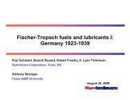
F. Plo,t Plan/General Arransement Draw£n~e<br />
Plot Plan <strong>and</strong> General Arrangement Drawings for Gas<br />
Fractlonation Unit 32 are us follows:<br />
Drawing No. Title<br />
D-32-PD-INP Plot Plan - Unit 32 <strong>and</strong> Unit 38 Gas Fractionation<br />
<strong>and</strong> HGT<br />
D-32-PD-2NP Elevation - Unit 32 <strong>and</strong> Unit 38 Gas Fractiouation<br />
<strong>and</strong> HGT<br />
II-1.2.13-13<br />
P
A<br />
11,<br />
x<br />
I-<br />
|<br />
a<br />
1i<br />
|<br />
1<br />
t~<br />
• w<br />
,w<br />
...~,<br />
:'~ D<br />
z&<br />
VZ<br />
, I , I ~ I 4t<br />
.... MATCHLINE ~ C~L ROAD E 7320<br />
. . . . FORCONT, DWO. O'25"PD'I<br />
L,<br />
~,,. ~ ~ ~I ~ ~! ~ ,..=, ,,.-", ~-,~.<br />
I<br />
I I<br />
, i<br />
• ~ .... I<br />
z[<br />
• ., i r,t ~i<br />
! I Ii<br />
I<br />
AIR COOLI~R$ A60~ PlPI~AY<br />
.!<br />
1 i I _"<br />
.J,,,~lsl I ~I t-,sol ~ cu~ i' --<br />
/~1 b I .-Ha4 ~1 I.}11 FJcl Iron LIC~;.<br />
____j-l.",l:,-,,-,~ ~,,I I~lrJcl |,ss~'o~.~<br />
4@
i<br />
0<br />
' FOR CONT. 0WGo -"<br />
P(:8<br />
,IZ-Ol-4GOI<br />
l'.',,<br />
F£,R OESf~N REP(~T n*n RR<br />
~OR CI=IEM APPROVAL ~,-,~<br />
]OR t l ~ APPROVAL ~=cw.,= ~'1<br />
I_SSUI~0 (~ll~qT R~VI(1K S~r COMF~ =evn~o~*=u ~JC THE I~.R4 H, PR~NS CB~pR~<br />
P~SADG~. C.r~.ll~,~I A<br />
I<br />
I<br />
,/<br />
!<br />
.,,,.<br />
e,,-,<br />
,..J<br />
.,.,J<br />
I---<br />
32"fl1"1101<br />
3Z-OI-IIOZ<br />
3Z-Ol.llO)<br />
32"01.1104<br />
32-01-1Z01<br />
)i-OI-IIOZ<br />
33"01-120$<br />
3Z-Ol-lZO(<br />
)2.01.110$<br />
)2"01-1Z04<br />
SZ'Ol-120?<br />
32"O1"1301<br />
)Z'OI'ISOZ<br />
32"01"130)<br />
SZ'Ol-1~O4<br />
3Z-OI-I)OS~,O, r.,,O<br />
)Z'OI-IS~A,,O<br />
32"Ol'i~OT<br />
3Z-01-130|<br />
32"O1-1309k,8<br />
32"01-1)10<br />
32"01"1311<br />
3Z'0l'1312<br />
3Z'01-131)<br />
3Z-01-1314/~0<br />
32"01-1315<br />
3Z-OI-ISIKA, O<br />
r3Z-Ol-131T<br />
3|'O1-131~ko8<br />
)2-Ol-tZZ0-A,O<br />
]2"D1-1321<br />
)2"0t-1501, 1502<br />
3|'01-150~1504<br />
)Z-Ol-15OS. ISOG<br />
)2"01-1S07. ISOS<br />
32"D1-1509, ISIO<br />
32-01-1513.1SI4<br />
32-O1-1SI5, ISIS<br />
~2"01"1517olS10<br />
32-01-151~,1520<br />
32"01-2101<br />
UNIT 3B iS PROPRIETARY.<br />
I _ 7<br />
AOS~OER DE(IHANII01<br />
DI~ERTANIZ(fl<br />
O~OLIH[ SPLITIER<br />
DEbOrAH IZER<br />
WATKR I~tAV DRUm I<br />
WATER 5RAW DNR413<br />
AOSOHBE~ O((TIIARI2ER REFLUX DRUM<br />
rATER K.~ ORUM<br />
D[PERTANIZER REFLUX DRUM<br />
OA~OLII~ SPLITTER REFLUX DRUM<br />
PEPROPANIZ£R H(FLU~ DRUM<br />
i i ii<br />
tbSQROERDE(THANIZERAIR COOLER<br />
46e-~lOER D[(THANIZ(A CHILLER<br />
Nt~'~OR8ER O((nUU41ZER HEROILEk<br />
O(PERTANIZLR AIR COOLER<br />
D[P(NTAMllEROYHO, CONG~ISER<br />
D(PERTAHIZ£R REROILER<br />
SPLITTER OOTTOI~ AIR COOLER<br />
GASOLINE SPLITTZR AIR COOLER<br />
GASOLINE SPLITTER REOOILE~<br />
LIGlff O~OLINEPROCOCT AIR COOLER<br />
tIGHT GASOLINE PRCOUCT COOLER<br />
DEPROPANI|(R FEED/'OQTTOM~ EXCHANGER<br />
ALKYLATION FErn AIR COOLER<br />
DEPR~PAMIZERR(FLL~COHDEI~$£H<br />
D[PROPAHIZ(R RrnOILER<br />
PROP~E PRODUCT COOLER<br />
ALKYLATIOI FErn lATER COOLER<br />
OEPENTAHIZER FEED/BOTTOU~ (XI~ANGER<br />
GASOLIHC SPLITTER FC[DIOVHD.E'~CHANGER<br />
ABSORBER 0EETHANIZ~ SlOE R[ROILER<br />
COLO LEM~OIL Pt,,MP ~0 SPARE<br />
LEAH OIL ~ ~ SPAR(<br />
D£P(NTARIZER 80TTOI~ PUMP M(D SP~E<br />
DEP(KIANIZ(R REFLUX PtJl~ A.'~D SPAR~<br />
DEP(HTNIiZER OVHO.PLZ4= A~ SPARE<br />
GASOLINE SPLITTER BOTT~PUMP NO, 2 At, O SPARE<br />
GASOLINE 5~LITTER OOTTOM~PUMP riO. I k~SPAR£<br />
CASOLI~( e..Pt,.:TTER PROOUC|/flEFLUX PUMP Atl0 SPAR(<br />
DEPROPAEIZERREFLUXPUMPAHD SPARE<br />
GAS rRACTIONA, TION REFRIG(RATION PACEACE<br />
~*, 18 ~ M &O • IO<br />
L tl I<br />
SC, M.b I" .llr-cr<br />
'<br />
e~'TT<br />
U.S. DEPARTHENT OF ENERGY<br />
V.R. GRACE & CO.<br />
50.069 B.P.O.<br />
~.~o~<br />
COAL,,- TO - HETHP, NOL - TO - GASOLINE PLANT<br />
PLOT PLAN<br />
~NIT 32 AND UNIT 38 tl<br />
FRACTIONATION AND HGT | D-32-PD-lI~P ,<br />
• I T<br />
A<br />
D<br />
2.<br />
I<br />
.o<br />
ii<br />
i<br />
i:<br />
[<br />
I<br />
fl<br />
i<br />
A
,0,<br />
¢<br />
D<br />
• ,, ...... ~'~'`~m"~'~'~'~m~'~'~'`~m'~+r`~m;~'`~':~r'~P'~++L++~U~,~?(~+!~+'+~; ', ~'~P`~t~`P'~'1'~/~+:'~'~'+~+~'~'~+'~+?~+P`~:~'d'+~%''~t;t~+P~+~'~;i~:~;~:~P:~ :,,+?,,, ,,,,,,, ,.,, ,..;;.+~+,;,,,,,,,,, ....<br />
Do~,~-PI>-I<br />
', . . . . I = I , ~ I 4+<br />
I)<br />
5<br />
..... I<br />
-- j<br />
• "tw..m___:~.'+o__+ _ [<br />
iZ<br />
I<br />
I<br />
I I<br />
}!<br />
SiP. PRCU =I.II~N~<br />
- -<br />
I I<br />
!i~ ,,?.t!]r.!!!, .,dl[- ~ i ...... ::..L~<br />
Watt<br />
•//,4.<br />
I ,<br />
'
u<br />
,,',:~ ~=~ .... ".",, ..... ~, .. .-.-<br />
~,~',~'~;<br />
[,--<br />
,v ,<br />
r IIA,~- |<br />
II-"" I~-R~ t i<br />
F,o¢ ¢~,~sM'I" ~ t , llP,,,,,~,,,o f-,'~l I<br />
I~,'~i[ cLilMTl~nlt~lNlluv*~°"'*'l I l THE RASH i. PAA:~ONS COMPANY<br />
~¢.noN /IJn.,cu~.T Iwt',~r IJ~-/i-/~.'ll PASADENA.~iUFORNIA<br />
/ i u _ i<br />
40 , 6<br />
I am<br />
/////%%%%%<br />
ii lid<br />
lr'- :Wl'<br />
U.S. DEPARTMENT OF ENERGY<br />
SAsKErr W.R. GRACE & CO.<br />
50,000 B.P.D.<br />
I<br />
7<br />
KENTUC, K¥<br />
UxJIT b~,4,MDIJ IT~ ~ I A<br />
pj.,-.no~'no,~ A~o He'T / I)-~-PI)-?.uP 1. ,~.~<br />
6 I<br />
__<br />
A<br />
D<br />
_?..<br />
A<br />
m.<br />
p<br />
l l
Fracttouation Un£t 32.<br />
G. Single-Line Diagram<br />
II I I i .... III|<br />
See Volume l~, 1.2.12(G) for the Single-Liue Diagram for Gas<br />
II-1,2.13-14
a ,<br />
C 1.2.14 IIF ALKYI~TION - UNIT 33<br />
/<br />
\<br />
A. Basis of Design<br />
A hydrofluoric acid (HF) alkylatlonunlt has been selected<br />
for the conversion of a mixture of butylenes, amylenes, <strong>and</strong> isobu~ne to<br />
produce alkylate as a blending component of finished gasollne. The IIF<br />
Alkylatlon Unit is a conventlonal-type facility v~thout octane upgrading. The<br />
HF Alkyla~Ion Unit selected Is based on a proprietary alkylatlon process<br />
llcenaed by Phillips Petroleum Company.<br />
The feed stream is derived from the conversion of methanol<br />
to gasoline in a Mobil ~ffG unit ~-~th subsequent fractionation to separate the<br />
butylene <strong>and</strong> amylene components in depentanizer <strong>and</strong> depropanizer to~ers. The<br />
feed Is depentanized to keep the C6+ fraction at a low level so that the<br />
hexane fraction is less than 0,2Z by volume of alkylatlon feed, This is<br />
necessary to reduce tar <strong>and</strong> decrease ac!~ consumption during the alkylat£on<br />
process. The feed is also depropanlzed to keep total propanes at a low level<br />
for alkylatlon <strong>and</strong> to reduce aeSd losses that occur when propane is vented.<br />
The feed contains a h~h-~mylene content~th about 60~ dry<br />
volume amylenes to the total olefins present in the feed. Phillips has<br />
exper±ence processing feeds with a hlgh-amylene content, up to about 31Z by<br />
vol,~e amylenes to the total oleflns present in the feed.<br />
The HF Alkylation unit product streams consist of alkylate<br />
as a gasoline-blending component, n-butane to adjust Easoline vapor pressure,<br />
<strong>and</strong> £eobutane to adjust gasoline vapor pressure ~r£th the excess to sales. The<br />
synthetic al~ylate product is about 7.5% by volume of the total ~asoline<br />
pool, with CS+ naphtha about 88Z by volume <strong>and</strong> the remainder butanes. Since<br />
n-butane ls in short supply <strong>and</strong> there is excess ieobutane in the feed, some<br />
isobutane Is added to gasoline when needed for vapor pressure adjustment of<br />
finished gasollne.<br />
II-I. 2.14-1
Provision for an n-butane side-cut from the deisobutauizer<br />
~s included in the HF Alkylation unit deeisn. The alkylate product should be<br />
£1exible in n-butane content to allow for a Reid vapor pressure (RVP) of<br />
total alkylate of about 5 to 6 psi for storage. When blending alkylate with<br />
naphtha for storage, a higher RVP is allowed; for instance, about 8 to 9 psl.<br />
Since the feed contains excess isobutane, the overhead<br />
product from the deisobutanizer is expozted for sales. The isobutane product<br />
is a high-purity stream with less than 0.SZ by volu~e n-butane content.<br />
Alkylat£on unit feed <strong>and</strong> product stream compositions are presented in the<br />
following tables,<br />
Propene<br />
Propane<br />
Component<br />
Isobutane<br />
l-Butene<br />
n-Butane<br />
Isopentane<br />
1-Pentene<br />
n-..Pentane<br />
Cyclopentane<br />
2-Hethylpentane<br />
C6+ Heavier<br />
Total, lb mol/hr<br />
Total, !b/hr<br />
Pressure, psia<br />
Temperature, °F<br />
lIFAlk~lnt~on Unlt Feedstock<br />
i<br />
|m mn •<br />
II-1,2.14-2<br />
lb mol/hr molZ<br />
0.01<br />
1.92 0.07<br />
933.70 34.11<br />
119.29 4.36<br />
291.43 10.64<br />
1,016.53 37.14<br />
192.54 7.03<br />
107,88 3.94<br />
11.03 0.40<br />
59.99 2. I9<br />
4.54 o.,4<br />
2,738.45 100.00<br />
178,900<br />
45<br />
100<br />
, II
C<br />
C<br />
Product Streams<br />
m<br />
Ieobutane Product<br />
Component (lb mol/hr) (molZ) (lb mol/hr) (molZ)<br />
. • .,L ,, , . . . . . . . . , •<br />
Propene . . . .<br />
Propane 1.92 0.35 - -<br />
Isobutane 552.13 99.22 12.20 4.42<br />
l-Butene . . . .<br />
n-BuCane 2.41 .43 244.24 88.47<br />
Isopentane - - 19.56 7 • I I<br />
l-Pentene . . . .<br />
n-Pent:ane . . . .<br />
Cyclopentane . . . .<br />
2-F~e thylpent ane . . . .<br />
C6+ Heavier . . . .<br />
AIL71ate . . . .<br />
~ L Z i ~ i<br />
Total, lb mol/hr 556.46 100.00 276.00 100.00<br />
Total, l"j/hr 32,315 16,310<br />
Pressure, [~,s ta 85 60<br />
Temperature, °F 110 110<br />
, .m i . i i , i i | . ,<br />
IT-I • 2 • 14-3<br />
l ,, , • , , ,, i i<br />
n-Butane Product Alkylate rroduet<br />
(Ibmol/hr) (molZ)<br />
i<br />
ii i<br />
N m<br />
44.87 2.80<br />
1,067.42 56.55<br />
m m<br />
107.95 6.73<br />
11.03 0.69<br />
59.97 3.74<br />
0.54 0.04<br />
312.00 19.45<br />
1,603.78 100.00<br />
130,196<br />
5-6<br />
110<br />
N
B. <strong>Process</strong> Selection RatLonale<br />
, . , ,<br />
~he Phillips EF Alkylation <strong>Process</strong> is a commercially proven<br />
technology. Phillips has about 80 plants operatlnS successfully throughout<br />
the world. Its capital <strong>and</strong> eperatlnE costs are lower than for the other<br />
processes examined. Phillips experience with hlgh-amylene feeds fits well<br />
with the present design, which contains about 60Z by vol,~e mnylenes to total<br />
oleflns in the feed. The process provides rellabilltywith a good turndown<br />
ratio.<br />
I. Operability. The HF Alkylatlon Unit can be operated at<br />
about 50~ of design capacity, It can be brought to full-load operation within<br />
a few hours.<br />
2. Reliabillty. The plant is designed with all pumps<br />
spared <strong>and</strong> with block valves <strong>and</strong> bypass valves installed around control <strong>and</strong><br />
relief valves. The design will permit maintenance on such items without<br />
shutting do~n,<br />
3. 0nstream Tlme. The operating factor for HF alkylatlon<br />
will be better than that of a fluid catalytic crackSng unit <strong>and</strong> is estimated<br />
at about 95Z stream factor.<br />
4. ~alntenance Costs. The maintenance cost estimate for<br />
| u<br />
the HF Alkylatlon unit Is 3o5Z of unit capital cost.<br />
5. EquLpment Lead Time, With the exception of the HF<br />
regenerator, the Phillips alkylation plant is designed entirely ~f carbon<br />
steel, The acid regenerator can be of either Monel-clad or solLd Monel<br />
construction. Monel construction is a major factor in determining the<br />
equipment lead time,<br />
6. Comm.erclal. Exper.i..ence. Table TI-1.2.14-1 summarizes<br />
plants using Phillips HF Alkylation <strong>Process</strong> in operation <strong>and</strong> under<br />
co~tractiou,<br />
II-1 • 2. I-',-4
q<br />
i m i~4"W~ZllJ~J~8~ANi<br />
Table IZ-1.2.14-1 - Racen£ Phillips HF AlkylaCion L~eensees<br />
Company<br />
Gulf 0il Corporation<br />
Harathon 011 Company<br />
Getty Oil Company<br />
Texas City Refining<br />
Ltndsey Oil L~mt*.ed<br />
BP Trading Limited<br />
BP ~ading L~nited<br />
Marathon Oil Company<br />
Texaco-Gul£<br />
Amoco-Murphy LtmiP-ed<br />
Mobil Oil Corporation<br />
Mobil Oil Corporation<br />
Gulf Oil Corporation<br />
BP Trading Limited<br />
CFR<br />
Mobil Oil Corporatiou<br />
Petrobras<br />
Trintoc<br />
~PC<br />
Albatross Oil <strong>Process</strong>ing<br />
Saber Refining<br />
Tenneco 0tl<br />
, . , | 1 1 .<br />
Startup Design Capacity<br />
Refinery Location Year (bpsd) (mtpd)<br />
Philadelphia, PA<br />
Texas City, TX<br />
81 Dorado, KS<br />
Texas City, TX<br />
Killingholme, Engl<strong>and</strong><br />
Rotterdam, Holl<strong>and</strong><br />
Grangemouth, UK<br />
Garyville, L%<br />
Pembroke, Wales<br />
Milford Haven, Wales<br />
Croydon, Engl<strong>and</strong><br />
Durban, South Africa<br />
Clnclnnaci, OH<br />
Kwlnana, Australia<br />
LaMede, France<br />
Saudi Arabia<br />
Cubatao, Brazil<br />
Point Fortin, Trinidad<br />
garri, Nigeria<br />
Antwerp, Belgium<br />
Corpus Christi, TX<br />
Chalmette, IA<br />
II-1.2.14-5<br />
1973 15,000 1,667<br />
1974 11,000 1,222<br />
1976 10,000 1,111<br />
1979 6,000 667<br />
1981 4,200 457<br />
1982 5,000 556<br />
1981 4,200 467<br />
1980 21,000 2,333<br />
1982 18,000 2,067<br />
1981 3,000 333<br />
1982 14,500 1,611<br />
1981 2,500 278<br />
1Q~O 2,000 222<br />
1981 3,000 333<br />
1981 3,000 333<br />
1984 14,500 1,611<br />
1984 3,000 333<br />
1984 5,500 611<br />
1983 3,000 333<br />
1984 4,800 538<br />
1983 7,700 859<br />
1984 16,000 1,778<br />
.ll
C. <strong>Process</strong> Descript~on<br />
Refer to <strong>Process</strong> <strong>Flow</strong> <strong>and</strong> <strong>Control</strong> <strong>Diagrams</strong> D-33-HP-INP,<br />
-2NP, -3NP~ <strong>and</strong> -~NP for eq~;.:~e~t arrangement <strong>and</strong> material balance.<br />
Depropanlzed hydrocarbon liquid from the Gas Yractionatlon<br />
Section flows to Feed Surge Tank 33-01-120S~ which has an 8-hr holdup to<br />
ensure continuous hydrocarbon £1ow to the HF Alkylatlon Unit. The hydrocarbon<br />
£eed eomposltlon is shown £n the above table aea mlxture cons£stlng o£<br />
butylene <strong>and</strong> amylene olefIns.<br />
The total hydrocarbon oleflnlc feed, along with recycle<br />
isobutane, is charged to the reac=or sectlon of the HF Alkylatlon unit. The<br />
combined feed is dlsperaed th;ough ~pray nozzles <strong>and</strong> mlxed wltb hydrofluoric<br />
acld before entering the reactor riser. The reactor operates by dlf£erentlal<br />
gravlty ~Iow <strong>and</strong> has no novlng parts such as Impellers or mixers; also, acid<br />
circulation pumps are not required. Total conversion o£ reactants to<br />
hlgh-quallty alkylate occuro almost instantly.<br />
From the reaction zone, the hydrocarbon components <strong>and</strong> acid<br />
catalyst flow upward to the settling zone. Here, acid catalyst breaks out as<br />
a bottom phase <strong>and</strong> flows by gravity on a return cycle through the shell side<br />
of parallel Acid Coolers 33-01-1301 <strong>and</strong> -1302 to the reaction zone, where the<br />
reaction cycle is repeated. Heat of reaction is removed by heat exchange with<br />
a large volume o£ coolant £1ow£9~ through the tubes. Cooling water used is<br />
available for further cooling elsewhere In the unite The hydrocarbon phase<br />
£rom ~he settling zone, containing minute quautities o£ propane, recycle<br />
isobutane, normal butane, pentanes, cyclopeut~ne, <strong>and</strong> alkylate, is charged to<br />
Maln FracClonaCor 33-01-1101 £or recovery o£ oroduct streams.<br />
The main fractlonator overhead is charged to ~F-leobutaue<br />
Stripper 33-01-1103 for H~ acid removal overhea~. The bottoms isobutane<br />
p~oduct is catalytically defluorluat:~d, K0H treated, <strong>and</strong> yielded as isobutane<br />
product. Recycle Isobutane, essentlal for £avorable control of reaction<br />
mechanisms, Is produced as a vapor overhead stream from she main £ractlonator<br />
II-I. 2.14-6
<strong>and</strong> also from the HF lsobutane stripper bottoms, The condensed <strong>and</strong> cooled<br />
recycle £sobutaue is returned to the reaction zone.<br />
The alkylate bottom product from the maln fractlonator<br />
containing about 2Z n-butane is acceptable for motor fuel blending. An<br />
n-butane product of about 85~ purlty <strong>and</strong> sultable for motor fuel blending Is<br />
taken as a vapor slde-draw near the bottom of the main Eractlona~oro This<br />
sldestream Is condensed <strong>and</strong> sent to storage for vapor pressure blendimg In<br />
gasoline.<br />
A small slipstream of acid Is wlthdrawn from Acld Settler<br />
33-01-1202 <strong>and</strong> fed to Acld Rerun Tower 33-01-1102 te remove dlssolved water<br />
<strong>and</strong> polymerlzed hydrocarbons. ~_ overhead product from the rerun column is<br />
clean hydrofluoric acid, which is condensed <strong>and</strong> returned to the system. The<br />
bottom product from the rerun tower Is a mixture of acld-soluble o11s <strong>and</strong> an<br />
HF water azeotrope. This stream is sent to Main Fractlonator Heater<br />
33-01-1401 to be dlsposed of by burning.<br />
Auxiliary systems included w£thtn the battery limits include<br />
(1) Acid Relief Neutralizer 33-01-1201 to remove HF from relief gas leaving<br />
the battery limits, (2) Recycle Acid Rerun Tower 33-01-1102 to remove<br />
acid-soluble o11s that occur in the reactor acid, (3) Acid Storage Tank<br />
33-01-1203 for anhydrous HF acld dur£ng periods when the unit is shut down<br />
for turnaround, (4) HF Acld Neutralizer 33-01-4102 for surface dralnage <strong>and</strong><br />
sewer drainage in the acid area, <strong>and</strong> (5) a change room <strong>and</strong> storage room for<br />
cleaning <strong>and</strong> storlng necessary protectlve clothJ.ng requlred on occaslon by<br />
operatlng <strong>and</strong> maintenance personnel.<br />
<strong>Process</strong> hydrocarbon vapors from the relief gas header<br />
containing HF acid are contacted in Acid Relief Neutralizer 33-01-1201 with<br />
dilute aqueous sodium hydroxide prior to entering the flare system. Calcium<br />
chloride is used to precipitate calcium fluoride from spent caustic in<br />
Calcium Fluoride Precipitator 33-01-4101. Insoluble calcium fluoride settles<br />
out to form an inert sludge, which has been successfully used as a sanitary<br />
l<strong>and</strong>fill ~r£thout known environmental problems.<br />
Y.I-I • 2.14-7
i ~ i m ~Itleo~,,~ tl~ tlWr e41~ ¸~ ~ , 4~ ~t~ ~ ~ e1,et~e~*l~fr~q 4 ~ le ~ ~le~ l l i ~ I<br />
Fro~ produc~ screams that require KOH treaters~ the spent<br />
KOH is processed through a spent caustic neutralizer using Na2CO 3.<br />
Drainage from the spent caustic neutralizer flows to the plan~ was~e~mter<br />
treament system,<br />
Product streams such as L~G, are defluorlnated over an<br />
activated alum2na bed. After the bed is "spent," it is considered ~nert <strong>and</strong><br />
can be disposed of ~n a sanStary ~<strong>and</strong>£111.<br />
D. Risk Assessmen~<br />
The hydrofluoric acid (HP) alkylat~on unit designed by<br />
Phillips Petroleum Company converts a m~xture of butylenes, smylenes, <strong>and</strong><br />
isobutane to produce alkylate as a blending component of f~n~shed gasoline.<br />
The Phillips HF Alkyiation <strong>Process</strong> is a ccunnercially proven<br />
technology. Phillips has abou~ 80 plants operatiug throughout the world.<br />
Phillips experience wi~h high-amylene feeds t~cs wel~ wi~h the present<br />
des~su, which contains about 60Z by volume amylenes co ~o~al ole£ins in the<br />
feed. The process provides reli~bil£ty with a high-onstream factor. The plant<br />
is designed with all pumps spared <strong>and</strong> with block valves <strong>and</strong> bypass valves<br />
installed around control <strong>and</strong> relief valves. The design permits maintenance on<br />
such items without shutting down. Corrosion <strong>and</strong> equipment ~ouliug are not<br />
expected to be problems. The technical risk is considered ~ntmal.<br />
ZI-I • 2.14-8
L" ~"<br />
E.<br />
are as follows:<br />
Drawing No.<br />
D-33-MP-INP<br />
D-33-MP-2NP<br />
D-33-MP-3NP<br />
D-33-MP-4NP<br />
IO I~lt~lh m~Qrtl~ pN ~ Nml<br />
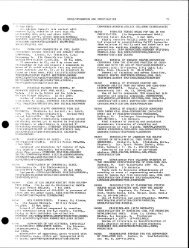
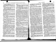
Pro,tess <strong>Flow</strong> <strong>and</strong> ,<strong>Control</strong> Dia~ra~_s (Including ~aterlal<br />
Balance)<br />
<strong>Process</strong> <strong>Flow</strong> aud <strong>Control</strong> <strong>Diagrams</strong> for HF KLkylation Unit 33<br />
Title<br />
PFCD HFAlkylatlon - Acid System<br />
PFCD HF Alkylation - Fractlonation<br />
Material Balance -~IF Alkylatlon<br />
PFCD ~Y Alkylatlon - Waste Disposal<br />
I'r-I. 2.16-9<br />
i !<br />
E*m
,,,, , ; . ,, • , m .~,,~ ,, • •, , i~ , ,,,i ,<br />
,,~t.~o~ 33-o1-I3o~ ~ 33-o1-,2o3 3,|.0~.t3o] 33..o1-13o5<br />
ACID COOt, EA ACln COOLEII ISO~UTAH[ IT[CYCLE ACID SETTLER ACID STORAGI[ ACID VAPO4~IZER ACV,~'S~[RTJF-'[~I"~f- £1!<br />
' ~ " " IUOCO0(,I~<br />
ALK~LATE FEEl)/<br />
FEEO SL~G[ TARK<br />
COOt.ING WATER SUPPI.YICUOLIIIG TOW~<br />
'1 "-~:" ("'J ' 1 I<br />
33-01-1202<br />
l-<br />
RF..A( TO~ RF.ACTO~ CWR ~'~<br />
OI~ICNIPI"ION<br />
I.~ RECYCLE ISOOUTANE ~ 0 6<br />
L-.J'-"- ~ 2o',..w-33<br />
cws<br />
[ I I I<br />
I ,.I L,, I I I I<br />
I t"°'l "''1'1 "vl~'l'~¢l"~"l°'~"'l<br />
SETTLER EFFLUUIT tic<br />
~ B~"A°33 HF VAPOR<br />
.~01 130-~<br />
33-01-150G<br />
~3-oH5o!<br />
33-01-IS~"5<br />
3'~-01-15o.i<br />
A rm RERUli<br />
m<br />
33-.01-1~06<br />
3,]-.01-1509<br />
i "~'o RELIEF HEADER<br />
14'-A-33<br />
H1TRO~ER ~<br />
3]-01-1102<br />
--el<br />
33-01-1508<br />
33-01-1509<br />
~DI FRACTIONAT~ FEED .,.<br />
PLI~ AHO SPARE<br />
iI c Is~v.I I linAwl r~ I I F~ an i.~:<br />
il n Ist~ni I leAwl r~l I F.gO_U~L~<br />
=1 AIv:v~ I I i i ;FO~S='L.',<br />
4,<br />
,'IK<br />
,,, . ~
:"4~ ~ a<br />
~u[,t He<br />
• ~ ~ L ~ . ,<br />
I I<br />
I'<br />
3S.-Ol-I to|<br />
ACZO~O~<br />
~<br />
STIIIP~JI4G |5OOUrAH£ ' ~ _<br />
e ~<br />
!~.,... ,,~,CLE<br />
33.-o1-1306<br />
llXt~lM<br />
33-01-1305/~e<br />
li~t#' Fqs~f~OaXTm<br />
~ , .~-i3(ClUU~£R<br />
~---~-~ NOT~<br />
1, 'fXE £00L1110 IfilEIt FACILCT~ FOR 1X£ H,F.<br />
ALKYL~T|OR UHIT 11; A Sf~,[~11[O S¥STEId,<br />
33-01-1]0a<br />
"R-]3-I<br />
2. "~X£ |SOOUTANE FLOg( LIH[ T~S|NTO TIIEISO-<br />
OtlTAV£ STIAtAC[ FACIL~Y AT "qlE PUll ~ °]SCitAItG£<br />
L1HE. (XOItMALL¥ NO FUR DURtKO UHiT OPB-<br />
' LSOOUTAH[ FLUSWSTOSAGE ~0-$7-ilP-4 liP U kT|0e).<br />
tHOE 2)<br />
ALKYLATE/llA~ FRACT|OHAT~ ~ 0-33,-MP'2 liP, J<br />
Hrll~,l rP.xcTloax~oa o~cm~o ~,cuuut.xT'nn, ~ o.-~].-i,-~ m, I<br />
|S06UTANE STI~PP[R<br />
I--<br />
I<br />
n~'mtrt<br />
RECYCLE<br />
¢ ~,~li~iu¢/<br />
]Sr41UTAi;'/<br />
~ O-33-11P'2 XP l<br />
RECYCLE ]SO~UTANE COilOEKSE~<br />
CoADrNSATL<br />
DAwN " '<br />
'~ .-. :.-.-..--~r n .... I I<br />
.... ,~=, Jw1'~L I c'"'' I I<br />
' ":]. ........ APPAOYAL I "'~uz'~'"D i n~K i11~J82<br />
, .... :..[[..IT II~'V~LL'I llaJ'i'li'u°~uiml FJC 11112/82<br />
lOlClOi~tol¢ ~iJ ~ .<br />
33-01-1307<br />
' 14"A'33- I<br />
Z'-A-33<br />
RECYCLE<br />
I$ORUTANE<br />
33-01-1308<br />
p t<br />
33-'01-130~A<br />
33-01._._- r~ ,m<br />
I i<br />
I PHILI.IPS PETROLEUM COMPHNY<br />
e ~ a,u~om<br />
EFFUENT Hr./<br />
WklN FILICTIOXATOR<br />
"el<br />
ACID IAI~ItI~US/$TORAG[}<br />
,,-----4 0-33-L~-2 NP~<br />
AC~O SO~L( czts,<br />
CA. S. O. )lmlN I~CT]OXATOR<br />
AI.KT~TU ~ D-$3-tlP-2 ~P I<br />
FRACT1ORATOR<br />
i~A-33<br />
ALKILAT( COOL~<br />
D335Pl KID. 0~,<br />
I<br />
EOUIPI~NT S.~Ot3 OH TXIS DRAWING<br />
33-01-II0Z 33"01-1307<br />
33-'01-1202 33-01-130B<br />
33-01-1203 33-01-130~<br />
3]'01-1301 :33"01-130~<br />
• 13-01-130Z 33"-01 - ISOG<br />
33-01-1303 33-01-150'/<br />
33"01-1304 33-01-1508<br />
33-4]1-1305 33-01-150~<br />
33-01-130(~<br />
I U.S, DEPI~RTHENT OF ENERGY<br />
e~sKETT V.R, GAACE & CO.<br />
' 5O, i~O B, PJ).<br />
bd~]~ e COAL - TO - METI-I~OL - TO "~oN[ - GASOLINE PLANT "G'~'~ ....<br />
1~ ~e~.,~z~,.N" I~nsnm cow~ | Acre ,STSTeU "~-33-MP- i' NP<br />
I o I<br />
7
,IP,<br />
c<br />
D<br />
I = I a I 4~ ="<br />
~ 33-Ol-131t 33-01-1313 33-01-II03 33-{<br />
MAtH F~CYIOHATOfl<br />
~<br />
MAtH FRACTIOtlATOI!<br />
' Sine emZL~ '<br />
~ 0 1 1<br />
MAt<br />
~Vm,~D CONOE,S~<br />
MAtH F~ACYIOMATIO(I RECYCLE ISOOtlTAHE |SOB TA~'~ 5"1RZPP~ |,~09,iJTAHE STRIPPER<br />
Oi/EIIIIEAD ACCUM~LATOI1 CONDFJSER FEED OOTTOI~ EXCHANGER " '<br />
'<br />
ISOOO"~j ',,<br />
X'-'----~<br />
-- .<br />
'(O-3]-if-I flPj ALKYLATE/AC]O VAPmTZER<br />
(D-33-HP-I HP I RECYCt.E L~O~UTAX.~<br />
150OUTANE RECYCLE SI;~LER<br />
~~--"]'BECYCLC Z:~QQUTAN,T."<br />
]SO~UTAIE R[CYCLECONDEHSF.,.R<br />
I D'33-i~-I NP~) "SETTLER EFR.UEHT HC/MA|X FRACY.<br />
FEEO °OTTOI~a EXC1L~G[R<br />
33-01=1401 3]=O1=I 101 33-01-!310 33-DI-12._._..._~<br />
MAt# FRACTIONATm MAI H F~CT,~OHATOfl, H'BUTAHE BUTANE KO~I<br />
33-01-I101<br />
-<br />
= ~---"-' " ,.;'-c~--~.~,l~ I"'~=:>-; ,-01 "~ -<br />
r-24"A-33<br />
33-01-1311A J T<br />
3"-'A-33 w.-<br />
"~24"-A-33 ~ 8"R-33- -J 33-01-131g 5'-~-3.3 3'-A-33<br />
33--01-1510<br />
~'0"33"1~1 ~-J ALKYLAT~[/IIA.tH FRACTIOIXT0~ FEED OOTTOId EXCIP, HGER<br />
I 0-3]-I~-I HP~ 6"-A-33<br />
ALI~TLATE/AC[O VAJ'~i~I~, MAIlt FRkCT|OILAI'O~<br />
FEED BOTTOMS EXCHANGER<br />
DRAWINa tt(O, !Ji<br />
33-01-1510 ]]-DI-I~;!<br />
33-01°ISII 33-DI-1513<br />
MAIN FRACTZCKATC~ M~IX FRACT]ONATOR<br />
REOOXLE~PUUP k SPANE REFLUX PUI~ k SPARE<br />
iltlllll'li<br />
1 I = I 3<br />
33-GI-1313<br />
I,I oL.~,<br />
I~1 c l~=e.<br />
I~;I e I~v=<br />
I~1 ~ I""<br />
,..I I .o.q.o.T.<br />
~ , ~ 12"-A-]3<br />
33"°~'I'°----~31<br />
33-01=13ZD<br />
ISORUTANE<br />
33-01.____~-<br />
I ]ex.I ~;1 I FOe CLX(~:<br />
I Ir~a] rJc] I Foe LXm,"<br />
I I I I I FOXSO~<br />
,t
. ;.:,c?t~ " - . . . . . . . . . . . . . . . . . "'"'~',~.~.~".~v.~"c"~Z.t~,~r~.~,.,~,~,.....-~ ......<br />
6<br />
' +33-01-1320 3},'01-131? J3-01-I206 3Z~01-1207<br />
t~'~'-~'tPPER. ALK'~LAIE~ ,~,, ISOOUTAH£ IS08UTAHE<br />
-- ~80.__~ pEFLU0flIHAI~ DEFLUOIIIHAI~<br />
3-Ol-IIOl ~c<br />
' p~FLt~pJmlm F(~. Dt[FLU~ImlO~, OfI:LUOHIHATOR"<br />
.~TTeOS (XC~H~m. .FE~ .(XTEn .ZSOOUTX.( CO0~.<br />
I(P'I'~'I ~ x3-Ot-I316<br />
I -l,~I,_i_O0<br />
I<br />
• - ;_.%~<br />
i+j<br />
k<br />
33-01-1315<br />
33"01-1206<br />
E'-A-'33<br />
Z3-OI-120T<br />
r<br />
/<br />
3'-A-33-I I 0-57-1P.5 14P~<br />
MOTOR FtJ~l.<br />
HORUAI, ~JlAH,T,/5TORL.GE<br />
~| \-/ i.~nUl~flU-I<br />
- Sl&~6E<br />
....,o<br />
"PHILLIPS PETROLEUM COMPANY<br />
• _ lWm.esv~ o v I<br />
FOR CliENT APpp,~tA~.<br />
I,,e, ,,,,+ i I<br />
,o._~,~,,~v.~ + ....... , I;"~:~<br />
~s=.,~,~ it-,., .... I I ~ p,'~. ~- zR~z^<br />
.'t~- I 5<br />
io,3w2m',<br />
WOI~<br />
h 'tl~ COOLING IMTER FAOILIIP/ FOil I~ r. ALK¥-<br />
LAlrlON UNIT IS A SEGREOATED SY~EM,<br />
SEE DWJ~tIXI4O HI'MP-15 14P<br />
~UIPWF.,HT SH011H nH TI~S DRAW'~6<br />
~LI-0l-I t01 33-01-1315<br />
33-01-1103 33-01-1316<br />
~,~-01-1204 33-01-1311<br />
't:~Ol-120G 3"t-D I - I :"llO<br />
33-01-12OT<br />
33-01-1208<br />
33-01-120~ 33-D1-131~<br />
33-01-13i0 33-01-|320<br />
3~-01-1311A 33-'01-1401<br />
33-01-1:3119 3'~-DI-15t0<br />
33-01-15ll<br />
33-01-I512<br />
33-01-1513<br />
ocA U.S. DEPARTMENT OF ENERGY<br />
I eAs~rr<br />
-i<br />
L .... co~-<br />
V,R, IgL4t:E & CO, '<br />
5o.e~n e.P.O,<br />
+o-,Em,~OL- [o.-GASm.E<br />
~mc~-<br />
PL~.T .<br />
i t- ,, I I<br />
A<br />
i<br />
E<br />
!<br />
.i<br />
i.<br />
I<br />
,I<br />
't<br />
il.__<br />
.+ I<br />
:! __,<br />
i<br />
.i<br />
,J<br />
i<br />
;1<br />
,i<br />
1 •<br />
I<br />
P<br />
i<br />
,<br />
i<br />
?,
_ I I I a I 4~ "!~<br />
A<br />
c<br />
COEIPOH~T<br />
PROtrudE<br />
WL.WT,<br />
42. 08 O. o1<br />
'i~ROPANE 44.09 I. 92<br />
iSnOUT~L 5e. 12 933.70<br />
I-.BUTEHE 56. IO 119.29<br />
N'-BUTAHE 58.12<br />
[SOPEHTAHE 72.15 I~01E.53<br />
I-PERTEHE TO. 13 192. 54<br />
N-PEtl:rAHE 72. 15 107. 88<br />
C~CLOPENTANE TO. 13 11.03<br />
2"IJETHI'LPENTANE O6. IT 59.g9<br />
,,C G 4- HEAVIER 4.14<br />
ALXYLATE 110.00<br />
! l~ I o,~ ~ PllCu CLIrNT 11<br />
ILYDROCARDOI4 |SOgUTANE H-BUTAHE ALKYLATE ASO<br />
FEED PROOUCT PROOUCT PROOUC?<br />
1.92<br />
552. 13 12.20<br />
291.43 ?..41 244.24 '44.87<br />
19.55 1,067.42<br />
101'.95<br />
11.03<br />
59, 97<br />
312.00<br />
'.TOTAL L6 MO:./HR 2. 738. 45 556.461 276.00 I~ E03.*/8<br />
TO|AL LES/'I,~ 178, 898. G 3.315`0 i 16.,309.6 130.19G.O ?6.6<br />
BPSO 20,332 3,915.0 1,909 13.B40 --<br />
LBS/Bbl<br />
211.26 198. 10 205.05 225,8<br />
IN<br />
65.3 58. I 59. I 81.2 --<br />
Dl~l~tW~r 14 )N<br />
I°I clu,v.l I (i~ r Jcl I roec~_[<br />
|~I e l~tnl I IRAwl irJcl I em L~<br />
s A 1115/
I i<br />
,,:, ,!: . . . . ~ , ,,:<br />
's~;(fl4a " I o I 1<br />
,;',,,,~,,, . . . . . . . . . . , . . . . . . . . .<br />
SO<br />
J<br />
J<br />
D<br />
J<br />
J<br />
J<br />
J<br />
7(,.~<br />
IF On e~s~t~ p~mX l ....<br />
i Fort ~ ,~rI~OVAL I1,-,-,,,,<br />
I FOR LICEN~I APPROVAL I"-"<br />
.4@ I<br />
REK<br />
F'JC<br />
t/tz/~zl<br />
[IIN9~<br />
PHILLIPS PETROLEUM COMPANY<br />
S<br />
THE I~UIH N. PIm~O/S CO4Pmty<br />
, PAS,~DEHA,, CN.IRI~IIA<br />
I<br />
I)3MP3WP. OGA<br />
NOTEw<br />
I, THE ~ WA~F~/L~Y f~ ~Fo ALKY-<br />
~H U~ ~A SEOn~1~ SYST r~<br />
2, TIl~ ]~UTAfl[FLUSII L~ r ~S INTO ZS~<br />
BIJTAN[ SIOI~4OEFA(~IJ[T¥ OH P~ DISCHARGE<br />
~,~ , (N~LLY #0 FLOW DURING U~T ~-<br />
]OH).<br />
US. DEPARTMENT OF ENERGY<br />
W.R.GRAOE & CO. xem.c~<br />
5B,BBca B.P.D.<br />
CON. - TO - METHANOL - TO - GASOLINE PLANT<br />
" I<br />
A<br />
J<br />
B<br />
D<br />
p
, . ~ - - _<br />
A<br />
¢,<br />
c<br />
D<br />
..... .. ,l'.-JS-~T<br />
I O'S~"~-~ ~,~" C ~ , , ~<br />
', I .... • ,I + I 4~, ,,+,<br />
I~l~--" IATL~<br />
~D-S2'-'MP"9~ I SLUOGEtHYDROCLGH[ U~ERFLOI TANK<br />
_ + . + ......... i+<br />
t<br />
1 t<br />
mXll(O TEE%~t , , USTIC<br />
---] ~1 TO FI.~RE XEAOER ~t,<br />
I~i ~'~'- XF ACID E[LEFI XF ALKYLATiON UNIT<br />
DI~SCfllP'rlON<br />
33-0!-120|<br />
_+<br />
E<br />
I<br />
I<br />
il<br />
33-01-1514<br />
33"01-1518<br />
v<br />
51EAM<br />
33-0|-1514<br />
33-01-1515<br />
CJIUSTIC CI~CULATZON<br />
P~P AND SPARE<br />
NO. DATE 'TI.~ Sl~ PIICU¢ CLIENT nferl!PT :IN<br />
.~UTmU.nm I,el '.<br />
FLAKED CAUSTIC FROM<br />
~OH TREATERS<br />
[ ~ AIR<br />
"--~" I ~)lE<br />
(SOLIDI<br />
~OTI FOR ~(~1'<br />
o<br />
f FOR ~Ir<br />
R ~tlTl~ P~V ~Jc<br />
I A ~||11: PAW F~ I FOR cL1r<br />
NO, .OAT[ lit ~D ~ I~OJ =i.i[m" I O "<br />
i ,<br />
F<br />
m
, , : , ; , " ~ ' - ....... ~ .... " m ~ ~ -~- " ..... ~ . ' ~ -: .... I]"',:,<br />
:~!i4~ 5 I • I 7<br />
..i.,~ ,. ii iii .II.H / i<br />
E<br />
33.'01-4102<br />
~t.~,,Ull FLUOA~E .H, Fo ACIO N~TI~Lt2B NOTES=<br />
rpRI~.C, IPITATOB I. REMOVABLE Gi]AT'~ n FOB gozCOz N]OmOl~<br />
1'<br />
=OTE KOTE<br />
,.4m,<br />
J<br />
FOB__OLq___~ nt~:0Ar<br />
I F()A ~_~BT.., ~ppflOVtqL<br />
F~e_t.~.aT, Oe ~ereOVAL<br />
! ~oB..cu__~ em Renew<br />
4-~ "~" ""<br />
=..-~<br />
33"U1-'1102<br />
33-01-4101<br />
$ flOzCO=<br />
SURFACE DRAZHAGE/UNZT 3] ~ I~<br />
LEVEL<br />
''" J<br />
II ...... I J<br />
i'"'='"1 I 11£ ~ H. I ~ C ~<br />
II 'u'voeu=m' I n , PASXODS, r..A~,t~IA<br />
I s I<br />
v<br />
REFZEERYIASTE [ D'S3"I~SI(P'~<br />
IIATER REJECT/D~PO~L<br />
D331aP4HP. DOA<br />
EQUI,°MERTSHOId40~iTI~S DRA'NZN~<br />
33"01-1201<br />
33"01-1514<br />
33"01-15i5<br />
33-01-4101<br />
33-01-4102<br />
US. OEPARTHENT OF ENERGY<br />
BAS~TT V.R.GRACE & CO,<br />
5~.gBB B.P.O.<br />
COAL - TO - HETHANOL - TO - GASOLINE PLANT =<br />
,F AI.KYLXn=~ - mm z= I=-,.---.,,,= ' IAI<br />
.menZSeO~L | D-33-MP-4 HP I'c-.~<br />
• I J<br />
A<br />
~0
~ i I ~ t U f l l m ~ , ,, ,<br />
Unit 33 are a~ follows:<br />
F. Plot Plan/General Arrangement Drawings<br />
Plot Plan <strong>and</strong> Ceneral Arrangement Drawings for HF Alkylation<br />
Drawlng No. Title<br />
D-33-PD-1NP<br />
D-33-PD-2NP<br />
Plot Plan - Unit 33 ~A1kylatlon<br />
E1evatlon - Unit 33~ Alkylatlon<br />
II-1.2.14-10<br />
m m<br />
p
N<br />
Y<br />
\ A<br />
._ ._'.<br />
¢<br />
,, ...... I = I ,- ~' I 4 i<br />
zQ<br />
f<br />
I "i ;if i'ii" -"<br />
_~. T. T, T,"r ";D ~'<br />
liP.,"! NI<br />
=;-- ±'_~_,; -~ "l , ,<br />
olo,:,! ~i<br />
. i l l _ _~lTO!.'r<br />
i ,,.! i.. ! ! iii<br />
I II ! ! i iii : i l LIMITS<br />
II--L.--L ; i in<br />
i I1~ ! i !ii i i<br />
i Ilml! ! i !!! ~ii<br />
i II i,,I II ~ i **~ i!l H<br />
-@ ll--G ll! II<br />
.,I I. i i lll ..1_ I il<br />
ill.ill t![illil _,,<br />
"'i I~ I I ~;i!l ~ I t "1 "'-....I ,.L--'- I<br />
/ it<br />
:,,,1 "q ,,nl,,"l I,,~ f_ ,,,..<br />
oo o u al o'~" i i ~,,,i"<br />
I.=..=.1 I==,=,=1 II ]'---..I I<br />
..MATCH L,!NE & C/L ROAO E. "1090'-0'<br />
"'- _, ,~,,. , , ~i~... i~, , I,-'"~ ,-.. I I I I<br />
!i1~ ~tl~ di ~ ..... .---.:.,l<br />
~]; ,,~:li.f..~l.5,12_~.. ~ it~ t.~ .,%l...lli .jSj p<br />
oil~ - - 3~1"0l'1513 "-- " 3]-01-1511-<br />
OPF.RATOnS<br />
CI.liLIIGE<br />
llOOi<br />
II I I i / r , I1', . . . . . f ..,..<br />
,, .' .' ,, . i ~ if'. i t ! ]~:~. I<br />
........ I~ I . . | . . l . I I ~ . I !I . , , . t . . . . ~,~7<br />
~a:V.L:L~ I I I I I . . . . . .<br />
'-i-"--e-'i-"l'--l--i-- I ; I z ! | --;-- ,-I.--~ BATTERY<br />
~1 "~'1 ,,,J ,,,J , ,,,c ~ . . . . ~ LIWITS<br />
T~ T I ~ ~ ~ TI--I --I -'t --' .~ ~; ~I<br />
MATCH LINE III C/L ROAD £.6830'-0'<br />
f<br />
lira liil iimlll
i|l 11<br />
. . . . ,--+-.,.,-~',~.m+,++~+m'~+'.,-+'.,+,+;,,+~+,+~.+~+~+m,m~:,~,,:.,,-,~..+.,+ .,+ .<br />
+ . , r ~ . ~ + ~ ' ~ ~ , ," +~+'~',¢.+.~i ~I,~+~N,:..+/7_+,pI~7.~;~-+, ' , ,;+~+'~,t.'+. ............. ,'.v.,,+',',,..,, r,, ,.,. ,': ;+,, ,~,,: ~,+. +.:,.++;~+.,,,+..., :,+ ...........<br />
,+ + I ,, o I 7<br />
33-01-4102<br />
".! ........ ~- RB:~tIT ii;;" I.v/rJol II<br />
II'~'ll~n ¢~ J~wL Ilc.te,,~ I<br />
P. r,. D.<br />
33-oi-,16oi<br />
,m~.lo~ /', "~mcu~" I ~/~* I r-.,-J~l P&~DB~. CN.IFDI~I&<br />
4-~ [ ' "<br />
J<br />
, ii<br />
I<br />
i,o<br />
o<<br />
.,J<br />
l.IJ<br />
m<br />
.,-I<br />
-t,-<br />
U<br />
I--<br />
:+<br />
I<br />
EQUIPMENT LIST<br />
33-01-1101 MAIN FRACTIOHATOR COLLIli<br />
33-01-1102 ACID IERUN COLU#I<br />
33"01"110~ I,~)DUTAHE STRIPPER COLU~<br />
wsms<br />
:3-01-1201 ACID RELIEF HEUTRALIZER<br />
33-01-1Z02 ACID SETTLER<br />
33"01-IZ03 ACID S'IORAGE<br />
3,1-01-1204 MAIN FRACTIOFIATOR OVERHEAD ACCLIM.<br />
33-D1-1206 ISOSUTAHE DFJ:LUORIMATO~<br />
~3-Ol-120T ISO~UT/~I[ DEFLUORIHATOR<br />
33-DI-1208 ISOOUT~E KOIt TREATER<br />
33-Ol-IZOl DUTAHE XOfl TREkTER<br />
HEAT EkCHANGI~RS,AH'p COII~)I~I$[RS<br />
33-01-1301 ACIO COOLER<br />
33"01"1:302 ACID COOLER<br />
33-01-1303 ACIP VAPORIZER<br />
33-01-1304 StRIPPiNg ISO~UTAHE HEALER<br />
33"01-1305 ACID SUPERHEATER<br />
:3]-01-1:304; I$OeUTANE RECYCLE SUGCOOLER<br />
33-01-1~07 ISOBUT/~IE RECYCLE COt~EH$[R<br />
33-01-1308 MAIN FRACT, I~. RECYCLE EXCHAHG[R<br />
3].Ol-I]Oq.l~O MAIN FRACT FD. BI"MS. EXCHANGER<br />
]]-Ol-I]lO N-RUI'AHE CO~ERSER<br />
33-D1-1311~,8 MAIN FRACY. OVERHEAD COHD.<br />
33-01-1~12 RECYCLE iSOOUT~E COND.<br />
33-01-1313 ISODUTANE STRIP. FD. OTMS, EXCH.<br />
3]-01-1314 DEFLUORIMATOR.FD. BIM~. EXCI¢<br />
33-01-1115<br />
:)3-Ol-131G<br />
DEFLUORIf;ATOR FD. It~TER<br />
OEFLUmlHATOA I5OBUTAHE CLR.<br />
33-01-t317<br />
33-0t-I]18<br />
ALKTLAT[ COOLER<br />
MAIN FRACT. SIDE ArnOILER<br />
33-OI.ISI~J MAIN IPRAC]. SlOE REBOILER<br />
~-OI-1:20 IS08UrAHE STAIPPE.R REBOILER<br />
UEAtm<br />
]]-~1-1401 MAIH FRACL REaOIIER HEALER<br />
e,w__s<br />
33-01-1506 ACID 12[RLI+I PLIP<br />
3]-OI-ISOT ACID RERU~ PI.M~SPARE)<br />
31-DI-1508 MAIN FRACL FEEO PUMP<br />
33-D1-1505 ~JklR IPRACT, FErn pLIUPISPAREJ<br />
~3-Ol'lSlO MAIN FRACT. R[OOILF.R PUMP<br />
33-O1-1511 MAIN FR~CT. RE~OILER PUUP(SPIR()<br />
33-D1-1512 MAIN ERACT. REFLUX PUMP<br />
33-01-1513 ICqH FRACT. REFLUX PUMPI ~ARE)<br />
33-01-1514 CAUSTIC CIRC. PLMP<br />
33-01-1515 CAUSTIC CIRC. PUUPI SPARE)<br />
31.01.41¢1 CALCIIM FLUORIDE PRECIPITkTOI~<br />
3)-01-4102 RP ACID NEUTRALIZER<br />
0 I0 ~Q 410 r.O I10<br />
L.~+-. ~ I l<br />
t,~[, P . ZIP-(/'<br />
U.S. IEPARTHENT OF ENERGY<br />
m rr VJR.GPJCE & CO.<br />
58,e~8 B.P.O.<br />
co~.- To- ,Em~OL - TO - G~SOLmE PL~T<br />
PLOT eLA, r,;'.~, o. I ,,'~,T" r',%-; I-"<br />
II f ..... j II1<br />
Io
_ ', i " I +' I ,,+,<br />
A<br />
,k<br />
¢<br />
- - w<br />
'~'-P,,I I i !<br />
,,+,-,,+z, I I I ~--~-~<br />
° ~I '/\<br />
"L! ,<br />
ell " I .... I--I I |']" " : I I I P--I"-,I-"F--PIT--~<br />
.~]~,A~,,..+,.~,+,,,~,,J.J;I]<br />
I m'm'l'+'°l I m°l'l'~ I<br />
BY IOKO ~Cl~C~p,c,- I ~_~- ~ ~<br />
I<br />
IL.<br />
~l,-Ol,ttOlb<br />
aHI~I-I~48<br />
-_+--<br />
I 4~<br />
P
. . . . . . IIi<br />
,..~.#,¢ ,,* .... ~.,+ ,+ ,~<br />
_++<br />
, . I ' I ,<br />
/l\<br />
M<br />
'~).ot.t4ol<br />
nj i<br />
E<br />
r . DE OF ERGY +<br />
F ~ W.R. GRACE & CO. K~UC~<br />
- . ooAL-T H^.O" ~<br />
L.-~---"~"~"'~II -~ .... i-~ ; ; i .... F.~mw~ 11 ,~*" "I • + I + ] ^<br />
!~ecua'=l'~r~--~":"~ll ..... I I i IEMLPIIM. PAn.OnSCOUnav | UUtT 5~ l=,,==="--'~¢,.r,r..o=, o ].~...~/<br />
• 2 ==:"~m IL ...... I I ] pASAOENAC~I,I, IFORNIA-'--"" / &L~"fb~"('lOkl | v'~'a "v ,.,~r I<br />
40 , -- ,~. -- --<br />
reel<br />
D
Ci G. Si~gle-Line Diagrnm<br />
f ....<br />
Alkylation Unit 33.<br />
See Volume II, 1.2.12(G) for the S£ngle-Line Diagram for HF<br />
II-1.2.14-11<br />
._
1.2.15 ACID GAS REMOVAL - DNIT 34<br />
A selective Rectlsol process has been selected to remove sulfur<br />
compounds (H2S/COS) <strong>and</strong> carbon dloxlde (CO 2) from a coal derived eynChesls<br />
gas. The process uses methanol for physical absorption of the acid gases. The<br />
licensor of the proprietary process selected for this project is the Lotepro<br />
Corporation. The shifted <strong>and</strong> unshlfted feed gas streams are washed<br />
separately. In tbe regeneration of the methanol, sulfur-bearlng gases are<br />
isolated <strong>and</strong> transferred to the sulfur recovery unit for the production of<br />
elemental sulfur.<br />
The Acid Gas Removal unit product stream consists of purified<br />
synthesis gas that is compressed <strong>and</strong> used for methanol synthesis,<br />
A. ~asls of Design<br />
In the selection of an acid gas removal process, the<br />
following design parameters had to be fulfilled for a c<strong>and</strong>idate process to be<br />
considered:<br />
(1) A treated product gas purity of less than 0.1 ppmv<br />
total sulfur <strong>and</strong> 3 to 6 volume percent CO 2 achieved by<br />
absorption of CO 2, H2S, <strong>and</strong> COS from the feed gas.<br />
(2) The CO 2 tall gas stream must contain less than I0 ppmv<br />
of total sulfur so that it can be vented to the<br />
atmosphere without thermal incineration.<br />
(3) An H2S-rlch acid gas stream containing a mlnlmum of 25Z<br />
H2S <strong>and</strong> suitable for a Clans unit feed must be produced,<br />
(4) The technology must be commercially proven.<br />
The followlng feed <strong>and</strong> product stream data summar~,zz the<br />
normal operating conditions for th~ four-module Acid Gas Remov~l unit.<br />
TI-I.2.15-I
Component<br />
H2<br />
CO<br />
Ar<br />
CH4<br />
CO 2<br />
H2S<br />
COS<br />
02<br />
Total Dry', lb mol/hr<br />
Feed SCreams<br />
Shi£ted Feedgas Uushifted Feedgas Str~ppir~ Gas<br />
(lb mol/hr) (Ib mol/hr) (lbmol/hr)<br />
73,546.7 23,511,6 -<br />
513.8 309.2 8,655.6<br />
12,820.3 28,463.3 -<br />
172.4 103.8 -<br />
214.4 129.0 -<br />
53,771.4 11,567.3 -<br />
1,~6.8 827.0 -<br />
12~! 51.0 -<br />
i w<br />
142~497.9 64,962.2 8,655.6<br />
H20 171.4 75.3<br />
Total WeC, lb mol/hr 142,669.3 65,037.5<br />
Total, lb/hr 2,951,690 1,401,320 242,500<br />
Pressure, psla 790 790 33<br />
T,~uper:~cure, °F 100 100 68<br />
~[T--1.2.15--2<br />
I I I I ' It
( ~,.<br />
Component<br />
H2<br />
N2<br />
CO<br />
Ar<br />
CH4<br />
C02<br />
H2 S<br />
cos<br />
O2<br />
Total Dry, lb mol/hr<br />
H20<br />
Total Uet, lb ~ol/1~<br />
To~al, lb/P~<br />
Pressuce, pB~a<br />
T~mperatuze, oF<br />
Feed Strea~s (Contd)<br />
Air to<br />
Torvex<br />
(lb ~ol/hr)<br />
3,077.9<br />
39,5<br />
m<br />
828.7<br />
3,946.1<br />
4~.4<br />
3,995.5<br />
87,810<br />
II-1.2.15-3<br />
63<br />
82<br />
~ash Uater<br />
to TatZ Gas<br />
~ash Column<br />
(lb mol/hr)<br />
30,595.0<br />
30,595.0<br />
551,200<br />
16<br />
100<br />
m<br />
m
,,'<br />
P<br />
Component<br />
H2<br />
"2<br />
CO<br />
Ar<br />
CR4<br />
CO2<br />
~2S<br />
COS<br />
O2<br />
Total Dry, lb mol/h¢<br />
H20<br />
CH30H<br />
Total Wet, lb mol/h¢<br />
Total, lb/;~¢<br />
Pressuce, psia<br />
Temperature, °F<br />
Shifted<br />
Syngas<br />
(lb mol/hr)<br />
i i lira<br />
73,392.8<br />
508.2<br />
12,819.8<br />
166.4<br />
196.6<br />
733.3<br />
Trace<br />
Trace<br />
87,817ol<br />
Product Streams<br />
m<br />
4.3<br />
87,821.4<br />
563,490<br />
760<br />
82<br />
Unohifted<br />
Syngas<br />
(lb mol/hr)<br />
i i<br />
23,359.5<br />
304.8<br />
27,880.3<br />
m<br />
101.2<br />
122.7<br />
3,4~0.2<br />
Trace<br />
55,248.7<br />
3.0<br />
55,251.7<br />
995,830<br />
IZ-1.2.15-4<br />
766<br />
82<br />
i ii i i i<br />
ii i , i<br />
Total<br />
5yuaas<br />
(lb mol/hr)<br />
96,752.3<br />
813.0<br />
40,700.1<br />
267.6<br />
319.2<br />
4,213~4<br />
Trace<br />
Trace<br />
143,065.6<br />
m<br />
7,3<br />
143,072.9<br />
1,559,320<br />
760<br />
S2<br />
Acid Gas<br />
to Claus<br />
(ib mol/hr)<br />
0.6<br />
119.7<br />
0.3<br />
Trace<br />
Trace<br />
3,331.7<br />
2,273.7<br />
62.8<br />
5,788.8<br />
m<br />
6.0<br />
5,794.8<br />
231,450<br />
25<br />
92<br />
m<br />
!<br />
m
, .,. , ~.,,, ,...,,,,,.,,..,,..,..,,.,,, ,.<br />
product Strqamo (Contd)<br />
J, i .i .,= ii . . • • . . =<br />
Total Waste- Water from<br />
Tail Gas water Wash Column<br />
Component (lb mol/hr) (lb mol/hr) (lb mol/hr)<br />
H 2 5.0 - -<br />
N 2 11.624.0 - -<br />
co 35.5 - -<br />
Ar ~.7.7 - -<br />
C~4 5.6 - -<br />
C0 2 58,354.2 - 19.9<br />
H2S O. 1 - -<br />
COS 0.3 - -<br />
02 ..... 360.2 - -<br />
T~tal Dry, lb mol/hr 70,432~6 - 19,9<br />
H20<br />
CH30H<br />
Total Wet, lb mol/hr<br />
Total, lb/hr<br />
3,511.4 327.7 27,480.9<br />
1~6 0.2 14.0<br />
73,945.6 327.9 27,514.8<br />
2,971,680 5,910 496,420<br />
Pressure, psia 16 46 17<br />
Temperature, °F 145 279 65<br />
II-1.2.15-5
C,,.<br />
f<br />
,,<br />
"<br />
B. Prouess Selection Rationa!e<br />
The selective Rectisol process as offered by Lotepro<br />
Corporatlon is a commercially proven technology. Its capital <strong>and</strong> operating<br />
costs are lower than costs for other processes examined, For th~ Gasoline<br />
Plant, the proces~ has been configured into four identical trains. The<br />
water/methanol separation is configured into two t~.ains. This arrangement<br />
provides flexibility <strong>and</strong> a high turndown ratio. The licensor guarantees the<br />
process performance <strong>and</strong> utility consumptions.<br />
1. Pressure. The higher partial pressure of CO 2 <strong>and</strong><br />
H2S in th~ feed gas results in increased absorption races <strong>and</strong> solvent<br />
temperature rises i~ the absorption columns, reducing the solubility of acld<br />
gas components in the solvent <strong>and</strong> requiring a higher solvent circulation. A<br />
cold solvent presaturated wlth C0 2 minimizes the solvent circulation rate,<br />
There are a number of Eectlsol plants that operate at higher pressures than<br />
this plant will require. No problems are antlclpated related to system<br />
pre s sure •<br />
2. Gas Impurltles. Impurities enter the gas purification<br />
,~t in the feed gas stream <strong>and</strong> are produced in the unit by side reactions<br />
with ciz~ulating solvent.<br />
A sldestream of spent methanol ~s continuously distilled<br />
in a methanol ~ractlouat,~r thst will remove all dirts <strong>and</strong> dissolved<br />
i~purities via a bottom waste stream.<br />
3. ,Malntenence <strong>and</strong> Operation Characteristics. In the<br />
Rectieol process, hydraulic turbines are not required to recover energy; it<br />
makes use of fewer rotary machines <strong>and</strong> vessels compared to competitive<br />
processes. Therefore, its maintenance cost will be lower than the maintenance<br />
cost required for other processes. Also, the Rectisol process should be<br />
somewhat easier to start up, operate, <strong>and</strong> shut down.<br />
II-1.2.1.5-6<br />
I p
4. Variations in H2S Concentration. The sulfur content<br />
of the coal may vary from 2.3 to 5.1 weight percent. The concentration o£<br />
sulfur compounds (H2S ÷ COS) present in the feed to the gas purification<br />
system may vary from 1.3 to 3.3 volume percent. In order to avoid large<br />
variations in B2S concentration of the ~eed going to sulfur recovery unit<br />
(~'htch may vary from 25 to 40 volume percent if not controlled), the gas<br />
purification system must be flexible enough to separate the correct amount of<br />
CO 2 <strong>and</strong> produce a constant composition £eed for the sulfur recovery unit.<br />
The Rectisol process achieves this objective by<br />
adjusting the amount of CO 2 in the vertt stream In a stripper/reabsorber<br />
column as discussed In the Rectlsol process descrlption.<br />
5. Equipment Availability. Equipment availabillty Is<br />
defined as the ratio of days each piece of equipment Is available to operate,<br />
whether operating or not, to days in a f£xed period of tlme (usually the<br />
period between two planned major overhauls).<br />
The Rectisol acid gas removal process uses conventional<br />
equipment, simple In design. The availability of equipment in the systems is<br />
better than 97%.<br />
6. Proven Technology. At least nine plants employing the<br />
Rectlsol process have been successfully constructed <strong>and</strong> are being operated in<br />
the United States. Table II-1o2.15-1 shows the list of the plants, plant<br />
capacities, <strong>and</strong> other process variables. Many other plants that utilize the<br />
Recttsol process are operated outside the Ur~ted States.<br />
C. <strong>Process</strong> Description<br />
Refer to <strong>Process</strong> <strong>Flow</strong> <strong>and</strong> <strong>Control</strong> <strong>Diagrams</strong> D-34-MP-1NP,<br />
-2NP, -3NP, -4~P, -Sh~, <strong>and</strong> -61~P for the acid gas removal material balance.<br />
The equipment arrsng ,~ent ie shown on Drawings D-34-PD-1NP <strong>and</strong> -2NP.<br />
II-1.2.15-7<br />
I
\<br />
Customer<br />
Texaco I~C. a<br />
Wilmlngron, California<br />
Texaco Inc.<br />
Montebello, California<br />
Table XI-1.2.15-I - List of Rectisol Units<br />
~ustalled in the United States<br />
Feed Gas<br />
Order (14HSCFD)<br />
1965<br />
1966<br />
Borden Chemical Co. 1966<br />
Geismar, Louisiana<br />
Roan& Haas Co. 1966<br />
Philadelphia, Pennsylvania<br />
Brooklyn Union Gas Co. 1968<br />
Brooklyn, New York<br />
Long Isl<strong>and</strong> Lighting Co. a 1969<br />
Holbrook, New York<br />
American Air Liquids 1969<br />
for Monsanto<br />
Texas City, Texas<br />
Celanese Chemical Corp.<br />
Clear Lake, Texas<br />
Syngas (Dupont U. S • X. )<br />
Deer Park, Texas<br />
aTurnkey ProJ eet<br />
i .i i • | • i<br />
1975<br />
1976<br />
80.0<br />
(H 2 rich gas<br />
from P.O.)<br />
0.90<br />
(a 2 rich gas<br />
from P.O.)<br />
17.0<br />
13.0<br />
12.0<br />
53.0<br />
(H 2 rich gas<br />
from steam<br />
reformer)<br />
(H 2 rich gas<br />
from P.O.)<br />
(H 2 rich gas<br />
from P.O.)<br />
11-1.2.15-8<br />
PreaBure<br />
(psig)<br />
460<br />
1,100-2,500<br />
300<br />
340<br />
340<br />
600<br />
340<br />
425<br />
840<br />
ni~f! ...... --rll<br />
Components<br />
Removed (vol Z)<br />
i i i i i •<br />
CO 2, H2S<br />
C02, H2 S<br />
C02<br />
C02<br />
CO2<br />
C02 , H2S<br />
C02,<br />
10.2%--20 ppmv<br />
C02, H2S<br />
CO2, tt2S<br />
(2 stages)<br />
.<br />
i
_ . . . . . . . . . . . . . . _ . . . _ .<br />
1. H_2S/CO 2 Removal. The shifted <strong>and</strong> unshifted feed<br />
gases that are supplied to the Acid Gas Removal unit in separate streams are<br />
injected with methanol tc prevent the formation of ice <strong>and</strong> hydrates as the<br />
gas is cooled down in Heat Exchangers 34-01-1301 <strong>and</strong> 34-01-1308 against<br />
purified product gas <strong>and</strong> cold tall gas. After s~paratlon of the condensed<br />
methanol-water mixture ~n Knockout Drums 34-01-1201 <strong>and</strong> 3/t-01-1205, the<br />
shifted gas enters Shifted Gas Methanol Wash Column 34-01-1101. The unshlfted<br />
feed gas enters Unshlfted Gas Methanol Wash Column 34-01-1104. Both streams<br />
wlll be washed with methanol,<br />
In the upper part of Shifted Gas Methanol Wash Column<br />
34-01-1101, C02 is removed to the required level with cold lean methanol<br />
from the warm regeneration section. In the bottom section of Column<br />
34-01-1101, H2S + COS is absorbed down to O.1 ppm. In order to minimize the<br />
temperature rise in the lower section caused Ly the heat of solution, a<br />
spllt-sUream of CO2-1oaded methanol from the CO 2 wash section of the<br />
absorber is used for sulfur removal. The heat of solution for the<br />
CO 2 absorption is removed by temperature rise of the downstream flowing<br />
methanol <strong>and</strong> by cooling the methanol In Exchanger 34-01-1302 against<br />
vaporizing refrigerant.<br />
As the solubility of CO 2 in methanol is less than the<br />
solubility of H2S , the methanol flow of the CO 2 removal section o£ Wash<br />
Column 34-01-1101 must be greater than to th~ H2S removal section. The<br />
methanol surplus from the CO 2 removal section of the tower is taken from<br />
the middle of the column.<br />
The uushtfted feed gas in Unshifted Gas Methanol Wash<br />
Column 34-01-1104 is washed with cold lean methanol. The purified gas leaving<br />
the top of the column is warmed in Unshifted Feed Gas Cooler 34-01-1308 <strong>and</strong><br />
then combined with the purified shifted gas. The heat of solution is removed<br />
by warming the solvent <strong>and</strong> vaporizing external refrigerant in Methanol<br />
Chiller 34-01-1309.<br />
1I-1.2.15-9
.::.', : ,,, '..',, ;,', I lJl ...[<br />
The H2S-loaded methanol from the mhe H2S-loaded methanol from the m<br />
34-01-1101 is routed to Recycle Gas Flash D~m 34-01-1203~ Recycle Gas Flash Drum 34-01-1203,<br />
at an intermediate pressure to recover dlssolved 1{2 anressure to recover dissolved 1{2 an<br />
from ~rum 34-01-1203 Is recycled by Recycle Gas Compressor s recycled by Recycle Gas Compressor<br />
feed gas.<br />
The same procedure is used £or the he ~ame procedure is used £or the<br />
from Column 34-01-1101~ which is exp<strong>and</strong>ed Into Drum 3~1, which is exp<strong>and</strong>ed Into Drum 3t<br />
£1aehed gases recompreseed by Compressor 34-01-1801. seed by Compressor 34-01-1801.<br />
The H2S-loaded methanol from thehe H2S-loaded methanol from the<br />
34-01-1104 Is flashed in Recycle Gas Flash Drum 34-oed ~.n Recycle Gas Flash Drum 34-C<br />
dlssolved I{ 2 <strong>and</strong> CO to be recycled vla Compressor 34-0P be recycled via Compressor 34-01<br />
from Drum ~4-01-1206 is flashed in the sump of CO StrlppinlS flashed In the sump of CO Strlppln<br />
to remove the bulk of dissolved CO. dissolved CO.<br />
2. CO-Rich Tail Gas. To limit the CO ~-Rich Tail Gas. To limit the CO ¢<br />
gas, a CO-rich gas is generated by exp<strong>and</strong>ing separately t~enerated by exp<strong>and</strong>lng separately tk<br />
from Flash Drums 34-01-1202, 34-01-1203, <strong>and</strong> 34-0~-01-1202, 34-01-1203, <strong>and</strong> 34-01<br />
34-01-1106. The C0-rich tall gas leaves the top o£ CO Lch tall gas leaves the top o£ CO<br />
34-01-1106. After warming in Exchanger 34-01-1301, it Isrmlng in Exchanger 34-01-1301, It is<br />
catalytic Incineration before venting to the atmosphere, before venting to the atmosphere.<br />
3. H2S ' Enrichment. The methanol from tzS Enrichment. The methanol from t<br />
34-01-1106 vtll be fed into HRS Concentration Colum~d into H2S Concentration Colum:<br />
increase the B2S concentration :l.n the tall gas feed to~entratlon in the tall gas feed to<br />
removal process, CO 2 is stripped from the vent ~tream in 3 stripped from the vent ~tream in<br />
of the column, <strong>and</strong> H2S Is rewashed In the upper ~ H2S is rewashed In the upper<br />
sulfur-free methanol from Drum 34-01-1202 not used for re~om Drum 34-01-1202 not used for re<br />
36-01-1106.<br />
The tail gas from Column 34-01-1102~e tail gas from Column 34-01-1102<br />
sulfur-free, The gas is warmed in Exchanger 34-01-1301, an1 warmed in Exchanger 34-01-1301, an<br />
the methanol content ls reduced in Water Wash Column 34=01-) reduced in Water Wash Column 34-0!-:<br />
• ~ | rl ,,i<br />
II-1,2.15-10 II-1.2.15-I0
t<br />
i<br />
I<br />
tl<br />
At an intermediate tray of Column 34-01-1102, cold<br />
methanol is withdrawn <strong>and</strong> used as refrlgerant in Exchanger 34-01-1307, To<br />
provide the necessary head, Pumps 34-01-1503 <strong>and</strong> -1504 are used,<br />
4. Warm Regeneration. The methanol from the sump of<br />
Column 34-O1-1102, now enriched in H2S , is pumped by Cold Stripper Bottoms<br />
Pump 34-01-1507 through Heat Exchangers 34-01-1310 <strong>and</strong> 34-01-1311 to Methanol<br />
Regenerator Column 34-01-1103. The complete desorption of H2S <strong>and</strong> CO 2<br />
from the loaded methanol will take place here by means of methanol vapors,<br />
generated In Regenerator Reboiler 34-01-1313o<br />
The vapors from the top of Column 34-01-II03 will be<br />
cooled in Water Cooler 34-01-1312 <strong>and</strong> then in Exchangers 34-O1-1314 <strong>and</strong><br />
34-01-1315 against the cold H2S fraction <strong>and</strong> refrigerant, The condensate is<br />
separated in Separator 34-01-1208 <strong>and</strong> routed back via Cold Stripper Bottoms<br />
~:'~ 34-01-1507 to the regeneration column, The E2S fraction leaving Drum<br />
34-01-1208 will be warmed in Exchanger 34-01-1314 <strong>and</strong> will leave the tmlt as<br />
feedstock for a Claus sulfur recovery plant.<br />
The regenerated methanol leaving the sump of Column<br />
34-01-1103 is cooled In Regenerator Bottoms Exchanger 34-01-1311 to ambient<br />
temp. :ature <strong>and</strong> buffered in Methanol Collection Vessel 34-01-1207 before<br />
being pumped to the methanol wash columns for shifted <strong>and</strong> unshlfted gas. Zts<br />
temperature is lowered in Exchangers 34-O1-1310 <strong>and</strong> 34-01-1307 against cold<br />
loaded methanol. A small portion of the resenerated methanol is injected into<br />
the two feed gas streams,<br />
5, Methanol-Water Se~aratlon. The condensate from Drums<br />
34-01-1201 <strong>and</strong> 34-01-1205 that contains a mixture of methanol <strong>and</strong> water is<br />
heated in Reflux Cooler 34-01-1317 <strong>and</strong> fed to Methanol Fractlonator<br />
34-01-1105, where methanol <strong>and</strong> water are separated by distillation. The<br />
column is heated by means of medium-pressure steam in Methanol FracCionator<br />
Reboiler 34-01-1316. The methanol vapor from the top of Column 34-01-1105<br />
ll-l,,2,15-11<br />
m
I i I I I I III'I~mUEmlEMI~<br />
/<br />
will be routed to the hot regeneration, while the water is withdrawn as<br />
waste. The reflux supplied to Coluem 34-01-1105 is regenerated methanol from<br />
Column 34-01-1103, pumped by Pump 34-01-1509 <strong>and</strong> cooled in Exchanger<br />
34-01-1317.<br />
6, General. In order to reduce the methanol losses, a<br />
methanol slop system is provided. Zt consists of a buried main methanol<br />
header wlth branch connections to all pieces of equipment where leakages of<br />
methanol can occur.<br />
The methanol header wlll collect such leakages Into<br />
Methanol Slop Drum 34-01-1210, also buried. Vertical Pump 34-01-1511 Is<br />
installed in order to recycle the solvent to the regeneration section of the<br />
unit.<br />
Storage Tank 34-01-1211 is used to store methanol° A<br />
fllllnE pump Is provided. The tank is used to collect methanol streams during<br />
plant shutd.wns. In such eases, when the methanol is not pure, It is made up<br />
through the regeneratlou section.<br />
D. Risk Assessment<br />
J<br />
Shifted <strong>and</strong> unshifted raw feed gases are treated in the<br />
Rectlsol unit for the removal of C02, H2S , COS, higher hydrocarbons, gum<br />
formers, <strong>and</strong> other impurities that are produced in the coal gasifler.<br />
Crude gas, saturated wlth water vapor, will he indirectly<br />
cooled by cold purified gas <strong>and</strong> external refrigeration. Icing will be<br />
prevented by the injection of methanol. The gas then enters the first<br />
absorber, where sulfur compounds <strong>and</strong> CO 2 will be removed to the required<br />
le~rel by washing the raw feed gas with cold methanol, The overhead from the<br />
absorber column is routed to the methanol synthesis unit, <strong>and</strong> the rich<br />
methanol from the absorber bottoms, after flushing <strong>and</strong> heating, is<br />
regenerated completely in the H2S regenerator.<br />
II-1.2.15-12<br />
P
m II 1 I[[ , ~ . . . . I II ~<br />
Although methanol is classified as toxic <strong>and</strong> flammable,<br />
these potential hazards are controlled to acceptable levels of safety by<br />
application of st<strong>and</strong>ard method~ for pl~nt design a~d operational h<strong>and</strong>ling.<br />
This plant wil! be the largest installation of its kind in the world. Thus,<br />
it is important to examine some of its ~tak factors <strong>and</strong> evaluate the process<br />
reliability.<br />
I. Capacity. The large capacity of the plant will not<br />
cause any processing problem. In order to avoid mechanical <strong>and</strong> installation<br />
problems, the system is designed in four parallel trains,<br />
2. Integration With Other..,<strong>Process</strong>in~ Units. The Rectisol<br />
process has not been ol~..rated in conJuction with the Texaco Coal Gasification<br />
<strong>Process</strong>. However, it has been used in conjunction with a different coal<br />
gasification process producing gas of similar composition in a plant in South<br />
Africa. The operation of the African installation has been satisfactory, <strong>and</strong><br />
there is no reason to believe that the performance would be different in the<br />
W.R. Grace & Co. project.<br />
3. Equipment. The Rectisol process uses equipment of<br />
simple <strong>and</strong> conventional design. In certain parts of this system, spiral wound<br />
exchangers are used. Lotepro Corporation has used spiral wound exchangers of<br />
comparable size <strong>and</strong> duties in its other installations without mechanical or<br />
operational difficulties.<br />
4. Pressure. There are several Rectlsol acid gas removal<br />
Installations that operate at higher pressures than the 790-psla pressure<br />
required for this project. Pertinent information accumulated from the<br />
experience with hlgh-pressure Ina~a!latlons Is incorporated into the final<br />
design of this project.<br />
The risk of designing a Rectisol acid gas removal<br />
process~lth a feed rate ~f 2 billion scfd at 790 psia has been reduced to a<br />
low level by attention to the detailed engineering design <strong>and</strong> accumulated<br />
know-how from other installations. The llcens~r guarantees a plant<br />
availability of better than 97X for the Reotisol section of the project.<br />
IX-1.2.15-13<br />
,, ,,t ,
t,<br />
~4 B. ,<strong>Process</strong><br />
Balance)<br />
Unit 34 are as follows:<br />
<strong>Flow</strong> <strong>and</strong> <strong>Control</strong> Dia~ram. (Including Hatorial<br />
Proco88 <strong>Flow</strong> <strong>and</strong> <strong>Control</strong> <strong>Diagrams</strong> for Acid Coo Removal<br />
Drawin~ No. Title<br />
m<br />
D-34-NP-INP<br />
D-34-HP-2NP<br />
D-34-MP-3NP<br />
D-34-HP-~NP<br />
D-34-1fl ~'-SNP<br />
D-34-MP-61~P<br />
PFCD Acid Gas Removal - Methanol Wash<br />
PFCD Acid Gas Removal - Gas Separation<br />
PFCD Acid Gas Removal - Hethano. 1, Cooling<br />
PFCD Acid Gas Removal - Methanol Wash<br />
PFCD Methanol Storage - Methanol Storage<br />
Material Balance - Acid Ca8 Re.oval<br />
II-1.2 • 15-1~<br />
,
~ _ ]<br />
, .. .* ILl L [ I I ,, m I _ _ _ IJ I II II IIIII [1[ r I _ _. '<br />
I,<br />
li<br />
r~<br />
I<br />
I<br />
l<br />
1<br />
A<br />
i D<br />
~[&,,Zl,-~e-) ~' I i~Ixxam, nl~x/mY£A/<br />
TRICIU.IXG IrILTI~<br />
i D'-Z3-HP-2 N?~, SHXFT(D F[F.O ~S/CO S~'l'<br />
i {-<br />
I il,,<br />
I~ OIIII'CtUDlr~m4 i<br />
1<br />
34-01-1101 /~ 1:<br />
.. i l<br />
/_/:',~_ I J I II<br />
. . . . . . . ~ '-'l,X ~. a.<br />
34,.'0t-1513<br />
' I!! I ] [ I<br />
_._,._,..]~1 "'<br />
I<br />
i<br />
~ ] I el ~ "l L<br />
" I I ' " I ' L"T"-<br />
I .~ .,....[t;I I I I I../T<br />
i<br />
,:,.c....,;~, . . I . I ,o, . 1 °"~ I "' ~1~1 "~''1 ~'<br />
I<br />
m<br />
~ 34-01-1101<br />
= ,,.,J I~.,., ,,,.,I *%'-<br />
I ll~J, I l~lIF~l" I ~<<br />
Lil~.,~ I l~Ifzl I m<br />
i I<br />
i<br />
:. °
.1<br />
Iw,<br />
~r3t DESICN ~P'~f IA,~<br />
II III i ii ii i I III i IIIIII i i I<br />
34-01-1302<br />
i<br />
+<br />
ii<br />
I I--I<br />
m<br />
m<br />
IJNSHIFTEO syl-oA5#14-ol'"l]O8 ~34"uP'4 m~l<br />
TAIl. 0'X~a4-OI-i401 L ~34i"411l¢<br />
TAll, ¢ASI,14-01-1 IOZ ~ ~<br />
i<br />
iit5 utIH£1
ira,., ~ i , i , iii<br />
C<br />
D<br />
{ ' ~ ' ~ TAIL G~S/]4-OI-I]OI A,O<br />
] o-34-'1m~'1 HY'~- ll3S I~THA~t./:~4"OI'IlOI<br />
~" ~S4-ur-I:Xe'l L[iN I~TltAIIoL/34-Oi;I iOI<br />
I U-~4-HP-I_ou'~ COl LOA0~ HE'TItANOL/<br />
34"01-1101<br />
,~;:, ' ,'~ ~;, :~'~ , ............,,,<br />
I I<br />
1 2 3 I<br />
O-34.,.IaP-I ItPl R[CY~E 0AS/ 34-Ol,-i'q01 A,B<br />
IJ,_.,I _. II<br />
i . . .... ,.1_.1<br />
..... if<br />
L._]<br />
(<br />
I S4*Oi-iSOI<br />
34-01-1320<br />
34"01-1i101<br />
R£CYI~.[ r~$ C~ESSOR<br />
ii i i i<br />
34"Ol~I |O:I 34"01"__~r~<br />
~CL_~..~.!<br />
i 34-01-120_.__~_3~<br />
I, !~o!J<br />
2 '<br />
I II i<br />
?<br />
34"0t'120Z<br />
ru'~v! qf'T )N<br />
)<br />
, , 4,11,<br />
34-01-11~<br />
11 o- l~..~,d I /I~A,I r:~ t "~ I row ~<br />
~1 e I~,~*J I IRAwFrJci I ~m<br />
~1 ~l~n,nl I In~lrJei IFO~:~.<br />
" ~ i ir~wlr~i .~ r~'<br />
I "~ F°*"P '~ I°'~[~l"°~l~'~q . ,-.A'<br />
45
+" "' II I<br />
J II II I i I II B ll~<br />
t ~t-Ol-IlO~<br />
I l'tlll nI'IJ~CM REPORT<br />
I trm area" ~+iL<br />
J. iti'vtso na I .rr.m-- ~.~Sm, sz.<br />
I fm tt~ +wIpt~vat<br />
~tm P,J I~M'IP ~ I+pCt;1<br />
~ i I~4131011~I'ION in<br />
4@<br />
m_____+ ~<br />
,.m-.m +,-m-mT<br />
r +, .Ct~,ot/( o-+4-w-+ ~1<br />
~--.-~..~ / ~ 34-01ol310 A,B If, C<br />
-+-y-+_ +.,o<br />
i t - +4-Ol-lSm l"t~'+J~4.Oi.l~ 7 LI~I+ UiTli~li~t# l,P'll'il"~ ~r><br />
il~lOl.# 34-0t-I)10 A.+ i C I ,1>-34.,UP-3 ~P~<br />
- ~ I-/~ " "<br />
341-01-150T 34-01-1503<br />
34-01-150B 34-01-150,1<br />
COLO StRb°P(R FTASH S(PI~Tt~<br />
BOTTOVS PUlP II SPAIIE ~i~(O pUMP II SPARE<br />
r l,,cqr19L~o ~m.<br />
IA,.H I<br />
~ NOV NI<br />
I~.,.,,--+-, TIE ~ 14. ~<br />
I 5 I<br />
' i ~11<br />
'11t i<br />
H:S-M~"TWiKOLI34-OI-IZO4~ ~ 0"34"u1~4 ~l<br />
R(CY~( Ol~ )4-Ol-lZOl ~+ 0-34-'II'-4 NPJ<br />
e I 7<br />
i i i ii , ......<br />
HOTt.~<br />
I, TIt~ (OIJII~NI SitOIM OH Tills IHb~XO<br />
(OUtPIt(MT SHOrn4 Oil TI~S DI~+IItMGI<br />
34-01-1102<br />
34-.01-I lOG<br />
34-01-1202<br />
3¢-01-12O3<br />
34-01-1307<br />
34-01-1~0<br />
34~1-t503<br />
34..01-150'1<br />
34--01-1SOT<br />
34-,01-1501<br />
34-01-ii01<br />
I)£~:~I~d~THEHT OF EHERGY'<br />
W.R.GRACI~ & CO. ' ~<br />
COAl. - TO - I~TI~ - TO - C.~SOI..IPIE<br />
~"~"~ /, "'~'"+'+-~ ""-, I"~L_<br />
o I<br />
m<br />
A<br />
++<br />
II<br />
i I, .......
I 0-~i-~i7 ~r)<br />
0-3+-t~l w %. _ I<br />
' ~ ~TIUII~ 34-01 - I~-01~<br />
, . . . . . . I ~ .... I + I , 4+<br />
34,,01-1)10 A<br />
~<br />
14-,OI - I~J<br />
H)<br />
34"~1-1~I<br />
, -" °'"'~-~" I::---<br />
4e I 0<br />
i i ii ii, i i i ~11 ii<br />
,c~ ~ ~ ~<br />
'r~cTzo,~o~ ovo~t~si.-o,-t'i'os ' ~''~'~'1<br />
~' ' ~mo,.',~s4.ot-t t~.t e-~4--'~ ~')<br />
I~TIiXI~ IAIfJV]I-~i-ll~ [ O-~-'t"'S E'~<br />
~ ~e~.~ C ~ ~<br />
ll{TH,~(X~'13-Ol-I~ma I O-.~.Ur'U m';~<br />
i<br />
h TIIEE~I~HT SlI01~ {~ Tiffs I~alIHO<br />
ISFOtl I~ll~ IRAIN, 111fd~ MIll |OUA<br />
1RAIli$ |#Tills UNIT,<br />
4,,~1 -I tO]<br />
4"01-1~1<br />
4"01-1~i<br />
4-OI-13IOA~ I, C<br />
34-01-1311<br />
~4-O1-1]1|<br />
~'gl*131l<br />
34"~1-131t<br />
~4-01-1~1<br />
~-01-1~l<br />
3401-1510<br />
.... ,n ,~.L~ I ~Jel~ BJ~.D.<br />
- TO - I~THAIO. - TO - TLL~L.~E PLANT<br />
I XCZO r,~ ~,~OV~ - UlCZT 34 ...~,~ .....<br />
D-34-~tP-3-HP<br />
I • - I "<br />
i i i<br />
I(IN11JDCr<br />
,T,<br />
r"<br />
A<br />
I tit
A<br />
D<br />
E<br />
I.~-~¢-w-i ~>-TAIL ~It34-01-li0T<br />
IIETNANOI. UI~T<br />
¢'~-'~'-m-~ ~. I ~c~t r~:.,.oo-o~z<br />
/<br />
34,,,01=1301<br />
[ O-Z4.-i~-I I~> LEAN UrTHAIV'I.J)'4~I - 120 X<br />
~D-34-1~'~ I(P I IAT[1~34-01-1511<br />
[ D-}q~F-¢ liP> t,,~l I~II~J~'O~J3q-OI-13GT<br />
I O-l; :.- : I~'~ CO R;L31 TAIL GAS/34-OI-I~OI<br />
I!1<br />
I l D'''''' ~,a ~,~.<br />
~..u ,.~. ---. I<br />
II<br />
qi.<br />
L...,Jl<br />
I)l~rJl~ 11~11104i<br />
34-01=1205 I<br />
"'A<br />
J I |.,J-~ '<br />
.. z ,, p-~l~l,,~,l~,,,<br />
34-O1-120G<br />
i<br />
I<br />
I<br />
ram,<br />
• ~ ~.J,'.s:g~.._z_._.~l~. ~ . ~ i ,,'.<br />
.. M<br />
t m N f
Ii i<br />
i ~ I iii,<br />
i i i<br />
I r~ r~vr~r ,u,,~,,t II'-". I ,I<br />
r ''~1 -~ ii~t.lll~. Liolilo ..~<br />
E'~---REFRIG. ~S r._l -<br />
-' I '<br />
,, _ I<br />
i m . I<br />
I<br />
I<br />
j LOTII~O mm,z~<br />
I LaiU law'nnsan ~amz:zl=~e ~ euraoz<br />
I I."oll [I['r~ II~OYAL I1-'.-,,-- I i I<br />
I r.~ ~Lrr. ~ r~r~ II"'-'l II ~ ~ II, PmlS{~ COiHIer '<br />
,, ,...+.,.,,o+, It'"'" i i • ,, rf,+,,om,,.,,~l+m,,~ •<br />
Di41~4r, DC~<br />
i ill ,,<br />
NOT~<br />
,. ~l,~%,y,, ~ ~,,,,,,l ~,,~ ....<br />
l~;~ ,,,'~1~. '~ ~.~ .......<br />
j,'<br />
[0t~t~lT SH0n 0N THIS OP, x.m.m~<br />
'34,,.01-1104<br />
34-.01-1205<br />
34,..01-1~06<br />
34-Q1-1~4<br />
:]4-01-1309<br />
14-.01-Z501<br />
34-Ol-g'lOI<br />
t.L5. 0EP.,~THEI, IT ''"0F F.HE~Y<br />
--O~Z~Tr WJI~,Ga~d:Z & liD,, KO.OC~<br />
~- TO- ~-~o:': G.~._PL~_<br />
~~,
A<br />
,1,<br />
c<br />
D<br />
I!L _,<br />
AW ,<br />
~'~- ~[,IJI I II/lll<br />
1<br />
i<br />
o<br />
I Ii ii : I ~d~<br />
F '-]1 -~ CO~EII~I E<br />
IDIEtCm WIIOU<br />
II I<br />
2 i i, I<br />
31-01-1 t05<br />
i<br />
'¢4-01-131~<br />
,,....,)<br />
3 I ....<br />
,'~' =' ~"," ';I.' ;,',,'1 I<br />
4~<br />
FRACT]ONATOII OVERHEAD/34-OI-1103<br />
"I/~TI~I~. WATER/,54:01-1~II'I<br />
METHANOL tlATER/34-,OI- I ~11"1<br />
L:i_ _J -.Jo.l J .... ,.~ = • .<br />
~L<br />
-I-<br />
-L<br />
m . .<br />
m
i UNIT 34 J ~_<br />
TRAIN 3<br />
IRAII~ 2<br />
I,'H ["r 34<br />
I1U,?N I<br />
O-34-tdP-3 I~P<br />
D-34,-MP-Z lip<br />
0-34.'4iP-3 t(P<br />
TAXL GAS/<br />
34-01-1107<br />
|<br />
-JJ~-,~,,--,,,, i .... i ~ I/'.'.'.'.'.'.'.'.'.~<br />
I -~'~ ~ ,,~,,~ ~,m~,,d .... I I l<br />
" I e<br />
$4,.01-1401<br />
I ,,,.. ~,~ II ..... J ! i 1HE Wt,PH N. Prl~8 ~Np~ly<br />
44b S<br />
r<br />
i<br />
NOTF.Sa<br />
I. T~M~'I~,I/OLIqlU~'IO(IAT~AI~MEBOKfd3ARE<br />
COloM I011~OFFO~ 11L4~S, THE STATE<br />
LI ~ TO ALL FOI~TI~ZNL<br />
~OLr'~UEHTSHOrd~THISDR&IlleC:<br />
34-01-1105<br />
34"01-131&<br />
34-O1-1401<br />
D3414~lIP. I)GA<br />
I " LLS, I)F..P/~TMENT QF ENERGY<br />
~s~rr WJRr, ORACE & CO,<br />
B.P.D. P ANT<br />
co,w.- TO- - TO- OnSOU L<br />
I;<br />
A~ cas ~ovA,. - u~ 34 t-'--" .."~--' ...... ' ,,,., i.,~<br />
zE'n~um. STOnA~ ! ...... U-=q-Mr'-: ~r" i,..~.~<br />
A<br />
D<br />
t~
A<br />
¢<br />
C<br />
*:r- -~2~- - -,,?.3 I I;t~ll<br />
1 I m I " I 47<br />
i+l I<br />
1 +<br />
STHEAU tltJMBER , ~<br />
STREAM RAMS SH[FT(D<br />
FEEOGAS<br />
¢OI~POHEH7 ~L. WT. LO-WOL/HR MOL<br />
Hz 2.016 i8~587.0 51.61<br />
Hz 29.016 • 126. 5 0.3G<br />
CO 28.010 3205.1 9.00<br />
Ar 39.948 43. 1 0.12<br />
CH I 16.042 53.6 0.15<br />
CO l 44.010 13~443.! 3T. 23<br />
HiS 34.08Z 351.7 1.02<br />
COS 60.076 3°0 0. OI<br />
0~ 32.000<br />
SUBTOTAL 35~E25.1 IOO.OO<br />
H~O<br />
m~e,<br />
18,016<br />
~2.o4<br />
,,. 53.2<br />
TOTAL 39,678.3<br />
Pr PS[A ?90.0<br />
T t °F ' I00<br />
STREAU HUMBER<br />
STRBd4 RAME ACID GAS<br />
TO CLAUS<br />
COLmO;4ERT MOL. NT. LB,.MOL/HR MOL<br />
He 2.016 0.2 O.OI<br />
flz 28.015 29. 9 2. 07<br />
CO 28. 010 O, I O. Ot<br />
Xr 3~'. 949 TRkCE O. 9 PPMV<br />
CH" I 16. 042 TRACE I. 3 PPit,/<br />
¢0| 44. 010 832. 9 57. 5'~<br />
HzS 34. 062 560. 4 39. 28<br />
COS 60.076 15.7 1.08<br />
p.oe 92. ooo<br />
SUBTOTAL 1,44T.2 IOO. 00<br />
HzO 18.016<br />
CHsOH 32. 04 I. 5<br />
tOTAL I. 448.7<br />
.P+, PS~ 24. T<br />
T. °F 92<br />
r + tlii<br />
I<br />
]~1 _1 i I<br />
.__i+l.. i<br />
$11[PTEO UHSHtFI EO UNSH]FTrn<br />
SYNGAS FEEDGAS SYH-GAS<br />
LO-~L/HR MOL ~ LEO-MOL/ER MOL 7. LB-MOL/HR MOL 2 LB-<br />
18, 348.2 83.57 5p818,0 36,15 S, 835. 4 42.28 2~<br />
127. I 0.58 77.3 0.46 77,5 0.55<br />
3205.0 14.60 T~ 116.0 43;61 li, 970. I 50,46 I(<br />
41.6 0. 19 2G.0 O. IG 25.3 q~. 19<br />
49,2 O. 22 32.3 0,20 30.7 0.22<br />
I<br />
185.3 0.64 2.891.5 17.61 070.1 8,30<br />
TRACE (0. I PPI, IV 20G. 8 1.27<br />
TRACE 12. 8 O. 08 TRACE<br />
21,554,4 I OO,_~ 16,241.1<br />
24. 3<br />
I00. O0 13,813.1 100.00 3. c<br />
I.I 0.8<br />
.21,595.S 16,265. 4 131813.g )4<br />
7(0. O 790. 0 765. 8<br />
82 |00 82<br />
WASTC WATER AIR TO TORVEX WATER TO TAP_<br />
GAS WASH COLUMN<br />
LB-MOI./HR I I,(OL ~. LB-MOt/HR I MOL 7. LB'-MOL/HR MOL Y.<br />
TE9. 5 78.00<br />
9.+ Coo<br />
207. 2 21.00<br />
986.6 ! IOPL O0<br />
15. 9 99. 97 12. 4 7649. 9 I OO. O0<br />
i '<br />
L~<br />
.W.,,m,--<br />
"[.55<br />
~.4~<br />
~.i5<br />
~22<br />
~oo<br />
r<br />
TOTAL<br />
SYN-OA~<br />
~L/HR<br />
t4.!e8. I<br />
203. 3<br />
lOb!T5.0<br />
EG. 9<br />
79. O<br />
[Tr, xc~<br />
TRACE<br />
hB<br />
35,010.3<br />
1'50. 0<br />
62<br />
LOAOED WATER<br />
~A FRO~ WASIf ~LUI~I<br />
z LS..~O.,,~<br />
*T.S~<br />
0,57 2~ 153.8<br />
28. 45<br />
0.,i9<br />
0.,22<br />
2.94<br />
too ool ~o :s3oe<br />
SIRIPPZNO<br />
GAS<br />
2, 163, B<br />
23. 9<br />
62<br />
u~.z<br />
TOTAL TAIL GAS<br />
100,00<br />
I00. O0<br />
~ LE-~IOL/;4R HOL ~ LB-HOI../I',R HOL Z<br />
62 0.01<br />
2. 506.0 16.45<br />
.... 8,9 0.05<br />
1 65 0.01'<br />
I,t 0,01<br />
S.O 14.$88.5 82.86<br />
F. Plot Plan/General Arransement DrawlnEs<br />
Removal Unit 34 are as follows:<br />
Plot Plan <strong>and</strong> General Arrangement Drawings for Acid Gas<br />
Dra~rlng No. Title<br />
D-34-PD-INP<br />
D-34-PD-2NP<br />
Plot Plan - Unit 34 Acid Gas Removal<br />
Elevatlon - Unit 34 Acid Gas Removal<br />
II-1.2.1.5-15<br />
~ lJmnmmm~--
4<br />
¢<br />
D<br />
zO<br />
i!1<br />
DNAWiNG Hg.<br />
I<br />
ENG~GE.Z) I t~?|)<br />
S<br />
DE~RIPTION<br />
1<br />
>.<br />
i_o<br />
I!L,<br />
WING NO<br />
I<br />
I , I ~ I<br />
OE~iCRIPTION '"'<br />
MATCH LINE ~" C/L ,~OAD . 7685~0"<br />
~] ~jOU] ~ ~<br />
..... I I I1.<br />
I1<br />
o i i ,'<br />
I " 11 Ii ....<br />
" I<br />
MATCH LINE 6 ~' C/L #OAO E.7..RgO" O"<br />
OEGCR II~[tON<br />
3<br />
Q<br />
D ~<br />
, i ill. _<br />
Iro~<br />
.J~ ~ s r..r.. ~ ._ ~ ~."~'_..-~-<br />
I ~ ~ ~ ~ . -
LI<br />
,,,, • ,<br />
• ,,,,..~I,," ~,'C,i ,,'/,,,",'~',", ' ,~'.~ ' ,,.., ~', ,' , ' ,,', ,, .,~ ', ' ,, , . . . . , .' ",,. , , ,.' ,,,'"J, ,!',' ' ~ ,,,,<br />
' I, .' "' "<br />
BATTERY" LIMIT<br />
I I,I<br />
~ - = , . . I~.I I"~"<br />
ACt • &<br />
/ \<br />
/ "\<br />
[dATrERy /.,/All F<br />
,Ulm<br />
I<br />
__J<br />
t<br />
\<br />
}<br />
IN<br />
NOTE5 :"<br />
h THIS; PLOT PLAN 15 Ot= MOOU~'.,~ P/OF<br />
4 MODC/t,~'S E¥~PT gOR/,t/l. ¢O.OAP~X',V,4T~"3<br />
2. d.;ATEL#.ITE MA/N2",~LOG.~6 "ril~ IS IM<br />
MODC/&E f I O~l&)"<br />
• 5. SATELLITE M.4tNR ~LOG,5~'49~ t~=lM MOO, D<br />
• "J OIV&y [OR ~.OC~TIOIV SE6" OVEI~¢.<br />
I~0? ~AIV p<br />
S', ~IFT E<br />
F I U.S. DEPARTMENT OF ENERGY KENTUCKY<br />
I--BASKETT W.R. GRACE & CO.<br />
50.000 B.RD.<br />
t COAI~- TO - METHANOL, ,,TO - GASOLINE PLANT<br />
" pLo~ ~N ~1" ~;-I~,8;" I'\~I •<br />
u.u/r-34 ~ ,~'o~ po-/,vp IP--~lJ~<br />
ClO 6, 45 REMOV.,dL I c..,'~ ;=" I . I<br />
,=====B<br />
IBl~lI=llll<br />
i i
u<br />
i<br />
i<br />
A<br />
41<br />
¢<br />
D<br />
I<br />
q<br />
!!<br />
I l I 3 I 4+<br />
HI IJlnl I llll I II ill I I H I<br />
H,,,/,',,,,, 1 I I ""<br />
J<br />
i,<br />
II<br />
!1<br />
I, M. ~ ~ ,I lii'i '<br />
J ! ! i ~ I*|1<br />
DMTC t oJ ¢UEN Dr,.f~,~i,;~ o ¢1 .:l ",~ .<br />
2 I 3 I 4<br />
, ,,i
, , + , . , ,<br />
~ r ,, ~ ' '+,'" " , ' P ' Pt ;'"<br />
,,,, ~,,,,,,,""~ +, ,,, , ,P. , ,, ,,,, ,,,,~,,,,,+ , , , ,,. , ," ,,,,, , ;.,.,.',',,,,, ,,:',,~ ,,,, ; . . . . . ,,.,,,<br />
, , , , ,<br />
_,++ + , I +' I<br />
t<br />
i<br />
i! I ilh<br />
,=<br />
' "'__lJI / ~mm,<br />
, " %,<br />
.=TW,<br />
+<br />
,"/.//i ////A%\\%<br />
/////<br />
MI<br />
II II II ITI<br />
F__ U.S. DEPARTMENT OF ENERGY<br />
L ~ _ ~ ~ ~ -I so,ooo B.RD. .<br />
-=.'-+~-~, +.,Pmo+~. I~ ...... +-,~+ I ~ ~ ' , ~o;o I 7 Z + ~ ^ :<br />
" "-+'mlmlr'/~'+C"'rt~"E,%~'-~l<br />
-,-.+.
~ I m m ~ m ~ @ N ~ l J w w ~ ~ e l ~ t i ~ e ~ i~ .... l ~ v~ ~ ~ i i ,~i 4 . . . . @ ~ , l ~ I ~ w ~ l i l t ~ , t ~ • ~Q~q~i~j~41~ I w ~ i ~ , * ~ t ,i i t ~ I ...... i<br />
f<br />
i<br />
x..<br />
...'<br />
\<br />
follows:<br />
O. si.gle-Line Diagram<br />
The Single-Line Diagram for Acid Gas Removal Unit 3~ is as<br />
Drawing No. Title<br />
D-51-EE-7NP One-Line Diagram- Unite 34 <strong>and</strong> 39<br />
II-1.2.15-16<br />
d !<br />
I
w<br />
A<br />
@<br />
C<br />
D<br />
J'POI/O~'41;O~<br />
5 ~r, tA<br />
J4,4 I(V"<br />
ZotU¢<br />
TiP. FOR f41 P/..AC~<br />
I ~ ~'L J4* O J /l~i-4r~O I<br />
,i4,l~V<br />
~U~ 8l-O~o~r<br />
I<br />
4160~ ~ ~ 4160V<br />
,14.51¢V<br />
SI'OIOJT<br />
I<br />
39-01-4602 ~1<br />
iooo ~vs ,:f, _<br />
480V<br />
DKSCRI~IrlON<br />
ii<br />
1 I<br />
e e ~" P.<br />
12.£X<br />
3~'0l-4~01<br />
34-01/04-460~<br />
34.SKY<br />
8115 51-02031"<br />
124"1.<br />
J~-OJ-~60~<br />
I000 KVA<br />
~.J ,$4.4 KV-<br />
r'~ 480 V<br />
~ 480V MCC<br />
SYMBOL I, IST<br />
4t<br />
[~ JKDliPJ VOLTAC£ Srl, ffrE..et, C~,~.ET~ ,<br />
INCLUOIHn FU$E$,$$rf.~OI.ID STAt~ TRIPI, PL<br />
RIO AHO DIFF, PI~OT, ~ JIOTOI~ D~.R ~00~ "<br />
$1 s TIJ~ D~'LAY PI'.AS£ OV¢'R C(1~7£11T R£LA'<br />
50 ' IAST,411W~OU$ PH4S£ OVER ~ T ~d<br />
SIN # Tlltr. ~4Y oVER C[IRR~T G~O~ F~<br />
PR~TECTIOtl<br />
PROTECT IOH<br />
o(~ mFF~.~rI~L c~e~.m" eCLAt<br />
OUTOOOR ~oem cieCmT e~x~ ~JTH<br />
DI$COI,~I~CTIH~ $11TCHE$<br />
o ~ 3 eosmcw swrc~, c~r~R OFF<br />
1<br />
$u1~£ ~P~ESTUR<br />
I~CTIFI~R<br />
CO~DelCTOR r.RO~U,!G NOT COt, ffECT£D<br />
- - ~ COHDUCTDR ,~RV~CTLrD<br />
R.~ERSE PO~R PROTECTJO~I R~LAY<br />
(~ LOSS OF ,'fIELD P~OT£CTIOtl ~l,.4r<br />
~R4TOR ROTOR OVZ'I~AI"II~<br />
~ OY£R "040 (r}F..F~L) FOR G~I, STArOR<br />
srNC#RO $OOPE<br />
GD;BCtTOR<br />
(~ I~.4R~ FACTOR<br />
i l I I I I I I I F'I r,-*-~.~'Ir.iJ,rAl.',..,.tl "" l,,'~rtr~m:i<br />
ill II Ill I<br />
~ o . I_i.~ I o^T~ i o. i=~l~cl~l~z.t I m,~). I I-~o-~ I ,,, [-~l~¢1~1=,~- I ..:"
llt ,,<br />
~T ~ F~JL T<br />
R IITH<br />
r<br />
A~<br />
:r<br />
s TA ro~<br />
gOUIID FAULT<br />
SYMBOLS<br />
+<br />
®<br />
[]<br />
®<br />
s I<br />
BIS, ~ ~tt~lCroR<br />
£u~crRIC41. OR JJECHIWI£4L IHTEIfLOCIt<br />
CDAW~TOR ~ttAllOUT TYPE<br />
~IIT¢'H<br />
FUSE<br />
POft£R CIR;PJJT ~f.AkT.R<br />
DR41rOUT Trl~¢<br />
AIR CIRCUIT BJ~.AKER<br />
t~MWOUT TYI~<br />
P1~$£ CeURRENT T~4NSFORI~R<br />
(C1") JNDIC4TIHG ~ RATIO I OUANTITY<br />
~O~'NTIAL TRAN~F. IP. T#<br />
3# 1090/1150 WA<br />
34.5 ~V-4Ir~V<br />
a~Z 41" 55"C<br />
3 I - 3 IrltlDIt~ P~tlER TRAN~F.<br />
C~OUHD CG~t£CrlON<br />
I~IER TR~ISF, OA/F4 ~W,<br />
P~TfI~9 SHOIrll<br />
.lit LqOTORe NUMBER IHDICATE$ HDR$~OI~R<br />
LOll' VOL f'AC,~<br />
~BIN,4TiOH MOTOR STARTER<br />
204 IHDIC4TE~ PRIP R4rIIIG<br />
OR CONTIHOUS CUI~RtHT P~Tltil;<br />
J~CRANJP,~tL J~Y INTERt~CK $ ~<br />
I~.WROL ~tlTCH<br />
i~ ABIETER SlfIT¢~<br />
V~ VOI.r~rER $~IrCH<br />
~T~$<br />
x auaCrTER<br />
DOt 9EdJHD<br />
PF FOIER FACTOR<br />
K~LD~ATT HOUR<br />
V VOLTI,'fTER<br />
PAllEt, gOURD<br />
LP • LI~tTII~ P.4I~I.<br />
-! r~*~ ~e.m~" ~ ~r~ I'~"~"ml I l THE RALPH M. PARSONS COMPAIIY<br />
i<br />
4+ I s I<br />
.ABBREV I A T IONS<br />
V VOLT<br />
W WATT<br />
KV KILOVOLT<br />
IWA KILOVOLT~:£1~<br />
ATI KILOflAI~<br />
lira k'E~ VO L T~>EB£<br />
PF POIER FACTOR<br />
AS MII~TER $~LECTOR $1rlrCtl<br />
its VOLTIIETER SELECTOR $1rlTCN<br />
H.O. HORk~U.Y OP~I<br />
II, C. NOR#ALLY CLOSE<br />
~CC ~eOTOR CONTROL Ct~ITOR<br />
.in. 0tll<br />
KILOWATT<br />
LTC LOAD TAP CHJJ~IHG<br />
Z X IIPEDI~C£ PERC~T<br />
SP SP&~<br />
LRA LOC~F.O R~TOR ,UP~'~<br />
FLA FULL LOAD AJ~'RES<br />
OMC. DtACR~I<br />
STR STARTER<br />
F~R F£t"OER<br />
PP FU~<br />
lip IIO~...~O~ER<br />
I OC. LOCA T IOH<br />
$~. $CI.PEM.4TIC<br />
OTr. O~;NTITY<br />
TfP. TI'PICAL<br />
U (NIT<br />
SILT. $1~EET<br />
~. ORaI #tG<br />
ClRC. CIRC(IL4TI~<br />
BLIP. ~.~ER<br />
ijJp.D JIPPROVED<br />
TR 1RAI#<br />
COM. O,I~REScJOR<br />
WTR. IMTER<br />
It;D. II~UCTIOtt<br />
THRU nmovcH<br />
ALXY AI.KYLATIOW<br />
nl~ Te~;FOfet~<br />
I U.S. DEPARTMENT oF ENERGY<br />
BASKETT W,R. GRACE & CO. KENTUCKY<br />
~, 50.000 B.RD.<br />
COAL "TO - METHANOL- TO - GASOLINE PLANT<br />
ACtD GAS REMOVAL U-34 ~ ''"<br />
leRocm~ ~ATER r~n~. u-~9| D-5 I-EE- 7NP I/-e:~<br />
6<br />
B<br />
I<br />
;1<br />
k<br />
t<br />
..1<br />
3',<br />
'i<br />
¢<br />
,:s<br />
j.<br />
I<br />
:4<br />
:i<br />
J<br />
]<br />
,]<br />
J<br />
J<br />
4<br />
,j
1.2.16 SULFUR RECOVERY (CLAUS) - UNIT 36<br />
The Sulfur Recovery Unit (SRU) is designed to convert the sulfur<br />
compounds in the acid gas £rom the Acid Gas Removal (Reetisol) Unit to<br />
elemental sul£ur, which will be recovered as a salable product. The tail gas<br />
from the SRU is £urther treated for the removal o£ the remaining sulgur<br />
compounds iu the Sul£ur Removal Unit be£ore being vented to the atmosphere.<br />
Two parallel, 50% SPJ3 trains are provided.<br />
A. Basis ,of Design<br />
The quantity of acid gas from the Acid Gas Removal - Unit 34<br />
requires that two parallel 50% SRU trains be installed. This arrangement<br />
requires less field £abrieation <strong>and</strong> provides greater operational flexibility.<br />
The £ollowing Reed <strong>and</strong> product stream data summarize the normal operating<br />
condition information £or the two 50% plants.<br />
Feed Streams<br />
Total Acid Gas<br />
Component (lb mol/hr) (mol%)<br />
H2 0.59 0.01<br />
CH 4 - _<br />
CO 0.34 60 ppmv<br />
C02 3,331.73 57.55<br />
N2 119.67 2.07<br />
A - -<br />
H2 S 2,273.71 39.28<br />
COS 62.80 1.08<br />
Total Dry, lb mol/hr 5,788.84 100.00<br />
Total, lb/hr 234,490<br />
Pressure, psia 25<br />
Temperature, °F 92<br />
II-I. 2.16-1
C Product Streams<br />
Component<br />
Tail Gas (end of run)<br />
(Ib mol/hr) (mo1%)<br />
H 2 67.14 0.88<br />
C~ 4 - _<br />
CO 130.90 1.71<br />
CO 2 3,199.96 41.75<br />
N 2 4,142.12 54.05<br />
0 2 - .<br />
H2S 79, 32 I. 03<br />
COS 2.28 0.03<br />
SO 2 39.74 O. 52<br />
$6 O. 34 440 ppm<br />
$8 2.10 0.03<br />
m<br />
Total Dry 7,663.90 100.00<br />
H20 2,514.08<br />
Total Wet 10,177.98<br />
Total lb/hr 311,960<br />
Pressure, psia 18<br />
Temperature, °F 280<br />
|,,<br />
II-l. 2.16-2<br />
Sulfur Product (end of run)<br />
(lb mol/hr) ~molZ)<br />
m<br />
i<br />
m<br />
m<br />
m<br />
70,430<br />
274.54<br />
274.54<br />
1<br />
274.54<br />
65<br />
290<br />
I00.00<br />
I00. O0
B, <strong>Process</strong> Seleetlon Ratlonale<br />
The Claus sulfur recovery process is universally used<br />
throughout the world for bulk recovery of sulfur from acld gases containing<br />
hydrogen sulfide (H2S) .<br />
An alternative method of recovering sulfur from such gases<br />
is to manufacture sulfuric acid. However, h<strong>and</strong>ling, storing, <strong>and</strong> shlppiug the<br />
quantities of sulfuric acid generated by this plant would be much more<br />
difficult than marketing the smaller quantity of sulfur,<br />
Hydrogen sulfide could be converted directly in a Stretford<br />
unit but with considerably higher Investment <strong>and</strong> operating cost. The largest<br />
Stretfcrd unit in the United States has a design capacity of 52 ltpd compared<br />
with up to 1,200 ltpd in the acld gas from the Acid Gas Removal Unit,<br />
C. <strong>Process</strong> Descriptio~<br />
The purpose of the sulfur recovery unit is to convert the<br />
bulk. of the sulfur compounds In the aeld gas from the Acid Gas Eemoval Unit<br />
to elemental sulfur. This conversiou is accomplished by oxidizing ~uurnlug)<br />
one-thlrd of the H2S In the acid gas to SO 2 with alr, The SO 2 will then<br />
combine with the remaining two-thlrds of the H2S to form elemental sulfur<br />
<strong>and</strong> water vapor in accordance with the following reactions:<br />
H2S + 3/2 02<br />
2H2S + SO 2<br />
H2S + 1/2 02<br />
so2 + s2o<br />
3S + 2H20<br />
S + H20 (Overall reaction)<br />
These reactions create temperatures high enough to sustain<br />
the reaction thermally, <strong>and</strong> they will continue to equilibrium. The thermal<br />
reactions are followed by three catalytic reaction stages to complete the<br />
reaction to practical limits.<br />
II-l.2.16-3
(<br />
%.<br />
The acid gas enters the plant through Acid Gas Knockout Drum<br />
36-01-1201 to trap entraP.ned llquld. The feed stream is metered after passlng<br />
through the knockout d1:um. Airflow from Combustion Air Blower 36-01-1801 is<br />
controlled to malnta.ln a 2:1 H2S to SO 2 ratio in Reaction Furnace<br />
36-01-1401. The scld gas feed to the reaction furnace is preheated with<br />
600-pale steam <strong>and</strong> is burned with the combustion air.<br />
The hot gases from the reaction furnace are cooled first by<br />
generating 250-pslg steam in Reaction Cooler 36-01-1301 <strong>and</strong> then further<br />
cooled by generating 50-pslg steam in No. 1Sttlfur Condenser 36-01-1302. Most<br />
of the sulfur formed in the reaction furnace is condensed in the No. I<br />
condenser from which it flows through a sulfur seal into a sulfur pit. The<br />
cooled gases pass through a wire mesh coalescer for removal of entrained<br />
sulfur <strong>and</strong> flow to No. 1Reheater 36-01-1307. In the reheater, the process<br />
gas is heated to reaction temperature with 600-pale steam. The process gas<br />
then enters the first converter, where the reaction to form sulfur from H2S<br />
<strong>and</strong> SO 2 will continue. The reaction is exothermlc <strong>and</strong> heat Is generated in<br />
proportion to the amount of sulfur produced. The hot process gas Is cooled in<br />
the No. 2 condenser by generating 50-pale steam. The condensed sulfur passes<br />
through a sulfur seal <strong>and</strong> into the sulfur pit. The cooled process gas passes<br />
through a coalescer for the removal of entrained sulfur.<br />
The second <strong>and</strong> third stages are slmJ.lar to the flrst stage<br />
(each comprising a reheater, converter, <strong>and</strong> condenser/coalescer). The final<br />
condenser produces 15-pslg steam to cool the process gas as low as is<br />
practical. The other condensers produce 50-pslg steam.<br />
The tall gas from the flnal condenser is sent to Sulfur<br />
Removal Unit 37 to remove the remalnlng sulfur components. The sulfur<br />
recovered is collected in a rundown pit. From there it is pumped periodically<br />
to sulfur ~torage tanks. The sulfur in the sulfur pit contains H2S <strong>and</strong><br />
polysulfldes so the pit vapor space must be swept wlth a." to prevent the<br />
evolved H2S from buildln E up to a potentially explosive concentration.<br />
II-1.2.16-4
The sulfur pit vent gas then is treated in the Sulfur<br />
Removal Unit for removal of the H2S.<br />
I. Flexibility <strong>and</strong> Turndown. Turndown of each plant to<br />
one-third of design capacity is possible with st<strong>and</strong>ard instrumentation.<br />
Features provided to give turndown flexibility are:<br />
measurable extent°<br />
(a) Metering <strong>and</strong> control valve rangeabillty; dual<br />
transmitters or other facilities are provided for<br />
turndown to 20% of design capacity.<br />
(b) The air blower is vented to the atmosphere to<br />
prevent surging. Automatic antlsurge control is<br />
provided.<br />
Turndown normally will not affect sulfur recovery to any<br />
2. Startu~. The SRU is started up by burning fuel gas<br />
with excess air on a cold startup with either fresh catalyst or catalyst that<br />
has previously been stripped of sulfur. This procedure allows the plant <strong>and</strong><br />
catalyst beds to dry out <strong>and</strong> attain normal operating temperatures before<br />
introduction of acid gas feed to avoid corrosive conditions. ~en an acid gas<br />
flame is establlshed~ the fuel gas is shut off°<br />
S~artup on a warm plant or catalyst that has not been<br />
stripped of sulfur 18 accomplished by burning fuel gas substolchlometrlcally<br />
as described under "Shutdown."<br />
3. Shutdown. Fuel gas will be burned substoichio-<br />
metrically with steam to strip sulfur from the sulfur-laden catalyst beds <strong>and</strong><br />
to sweep out acid gas reaction products.<br />
II-1.2.16-5
- ~ - , ~ . , - , ~ , . , ~ ,,,, ,,., °= ,,.,..,,,I..,,,,..,,_, .....<br />
Ii<br />
t ~<br />
D. 1~/sk AsSessment<br />
~ ~ 4 e*4~glU pJOIg ~ ~tQt rf~ f~n~ ~ ~*q~ ~ ~ i ~ ~t ~ ~ ,~6.4~ ~ ,~, i et ~f ~I ~4 * Jgp~i~ O m~w,i ,~ je ° . . . .<br />
Unscheduled emergency shutdown of the sulfur recovery unit<br />
can occur because of loss of the air blower, loss of flame in the reaction<br />
furnace, loss of boiler feedwater, or high-liquid level in the acid gas<br />
knockout drum. Unscheduled shutdown also can occur because of excessive<br />
condenser or converter fouling or e blocked sulfur drain line that builds up<br />
pressure drop over a period of time.<br />
In ~his design, two nominal trains are provided as well as<br />
spare air blowers. Each train h<strong>and</strong>les 73% of the gas flow for the normal<br />
operating condition case. High-liquid level in the knockout drum can be<br />
prevented by proper operation of upstream areas. Many of these Claus units<br />
have been operated successfully for years without unscheduled shutdown.<br />
The modified Claus process is proven technology, with<br />
hundreds of units £n commercial operation. This process meets the Best<br />
Available <strong>Control</strong> Technology (BACT) St<strong>and</strong>ards. The prime criterion for<br />
selecting a sulfur recovery system £s to meet the environmental restriction<br />
imposed by BACT. W.tth the BSRP ~ulfur removal unit, it also meets the Lowest<br />
Achievable Emission Rate (LAER) St<strong>and</strong>ards necessary for nonattaimnent areas.<br />
The construction material is primarily carbon steel. From<br />
many years of engineering, procurement, <strong>and</strong> construction of these units,<br />
select vendors <strong>and</strong> fabricators are to be used that have proved their<br />
equipment for reliability~rlth a minimum of maintenance. The availability of<br />
equipment for this unit requires a nL~u~numo£ lead time.<br />
Sulfur recovery units are considered highly reliable<br />
operating units with a minimum of maintenance required.<br />
II-1.2.16-6
E° ,process <strong>Flow</strong> <strong>and</strong> <strong>Control</strong> <strong>Diagrams</strong> (Including Material<br />
Balance)<br />
(Claus) Unit 36 are as follows:<br />
<strong>Process</strong> <strong>Flow</strong> <strong>and</strong> <strong>Control</strong> <strong>Diagrams</strong> for Sulfur Recovery<br />
Drawing No. Title<br />
D-36-MP-1NP<br />
D-36-HP-2NP<br />
D-36-MP-3NP<br />
PFCD Sulfur Recovery (Claus) - Reactor<br />
PFCD Sulfur Recovery (Claus) - Recovery<br />
PFCD Sulfur Recovery (Claus) - Recovery<br />
II-1,2.16-7
A<br />
4<br />
C<br />
• . 24"AA-3G<br />
[ "~l ~'- Z'-kt-3G<br />
wsx[ ~TEn<br />
ACre OA5 FErn II40RmL)<br />
lEACH 1RA~H)<br />
COGENT MOL, WT, LB-UOL,'H+<br />
H| 2,016 0.3<br />
n| 2I.OIG ' 59. P$<br />
CO 28,010 O. ,S<br />
C0/t , ,lq.0io t~SS, C';<br />
HIS '34.082 1135.65<br />
COS 60. O'lG 3 I. 40<br />
TOTAL<br />
e, ~.<br />
ZO~, 40<br />
24.+<br />
T+ "F ~2<br />
I ~ I ~ I<br />
START-STOP<br />
CONTROL<br />
SET •<br />
15 PSIO I<br />
3G-0H20I 3G-OI-13GG<br />
ACZO GAS K.O, OIIUR ACtD~A~IT..R R~CTIOM FURKAC[<br />
(I I)<br />
]6-OI-IS01<br />
3K'Ol'lSOZ<br />
FXGURE 4-Z<br />
24"-AA-36<br />
J 3G-01-120._.,.__II<br />
~ 1. 24"-A-3G-|<br />
36-01-1801<br />
36-01-1802<br />
3~-0t-150.__.__/ ~-01-1|01<br />
36-01-1502<br />
COMBUSTION AiR<br />
A~ ~a~_ BLBIER A~) SPARE<br />
__ NOTE 2 24'~U..3G.]<br />
I- 6oo eszo $T(X. -: I-"I<br />
24~.AA-35-I<br />
36-01-1401<br />
-t!<br />
g<br />
PU£L GAS<br />
2"S-36-][<br />
wl<br />
A"<br />
i ¢OMPOHleNT MOL. liT. LIS-.laOt../Kfl<br />
HI 2.01G 71.31<br />
CH, 1(,.012 IS.SO<br />
N z 28.016 13.45<br />
1:01 44.010 "9. ,¢1<br />
CO 21.010 q.?T<br />
AR 3~. $45 4. 23<br />
CH1011 32-04 0.4'1<br />
ET ILII~ 30. O? I. 53<br />
ETHYLENE 2|.0S O* 13<br />
PROPt'LIENIr 42.01 0.23<br />
I:'I~MI[ 44. 011 5. 4 I<br />
|SO'3UT&ME 58. I Z O. IT<br />
H-BUTA~( $8.12 O.O'J<br />
N-'BUT£~E 54.09 0.~<br />
[SOP(ITAN( 72.15 "I<br />
N-P;NTAN I:" 72, IS .,~O*OT<br />
I'-PENTE](E 5O. 12<br />
0.12<br />
0.03<br />
TOTAL<br />
e. ps,,A<br />
'129.15<br />
m<br />
T, °F 90<br />
++ : , __+_LL_L~ !<br />
I<br />
,.+x-.+ ~ . ~ ' .<br />
.
,,,, ,. +,' ,,,.., , ;. ',' +. +,, .'., ' , , ,+ , ,<br />
~,-01-1301<br />
35-01-I ~02<br />
' ~<br />
R~I, CTI011~F R ,<br />
SET e<br />
. ZB5 PSIG<br />
~..:~ I m' ~ ,r" I<br />
/<br />
l<br />
3G-01-1202<br />
i " ~ ip ~ . ~ :3"..S=31;-!<br />
+IT '<br />
~F'-DI-I~i)I<br />
e:t_ ~<br />
?<br />
E]<br />
ll.31<br />
13.q5<br />
.. 9.61<br />
: s..__.~2.<br />
" 4.23i<br />
0.13<br />
O, IT<br />
; o,_,...~oe<br />
.°.<br />
O. I~<br />
5 , I + O<br />
3G'-'JUL-~I-!<br />
5ULRJB/ kO, i CON~f.~g .....<br />
4a"S'3G'I<br />
BF'IK/ UNIT StJOHEADER<br />
3~'S'36"I<br />
GOO PSI ICOla)ENSATFJ OONOENSE~S<br />
~+',<br />
I<br />
I, IgE I'QUIPgENT SN0WN ON THIS ORAW'IMG ARE<br />
FOIl OHE OF 1"10 1RAIIt.",<br />
|, ~[11[ FOLLOWIN0 [OU]PMENT ARE NOT SlIOtlN WITH<br />
FURIIACB<br />
-.-p- ,o, ,tmn.mv .u~. ,o.',<br />
~1 - I- 403 AUX~[ALfly BURNER No.3<br />
]4~ -1404 AUX'[LIJ~Iy OURN~R NO,3<br />
3, IX[ IPIOURE I(t,fgOERS REFER TO TYPtCAL<br />
(I}UIPMEHI'$ COHFXGUHATIOflS SllOiH (~Z4<br />
ORA~NG D"OI-MP-2 liP,<br />
[OUST SHOIII ~ TH',S D~IIIHGs<br />
3G*Ol-t201<br />
~5-01-1202<br />
3G-01-1301<br />
3G-OI-130G<br />
~$-01-1401<br />
~11-01-1501<br />
~G--OI-15OZ<br />
3&-'01-1801<br />
31-01-1803:<br />
' ~-- O3~MPUfP, CGA<br />
-- U.S, DEP~eIRTI'4EHT OF ENERGY<br />
- ~ ~ ~ ~ ~ . ~ I i | net l,,. CmL - +o- ram,No, - T,o.- oAs~mE ~ANT_ ,~<br />
,:::++: +++-: r +°+++++ +--izi<br />
, ~ n ,^~.~. m,,~..,. I ,m.msEcm, | O-~G-M~-I .r<br />
'+ I + - . ' I<br />
A
A<br />
4<br />
C<br />
D<br />
I D-36"~-I I~' 3G'-AA-3G-!<br />
" SLILFUIPREAOTZOH FUP, KAC(<br />
_4~<br />
h ~<br />
:..-....<br />
q<br />
-P--~-'<br />
., ,,~,.,..,.~ ,,','~:~' ,'.~!B'~ ~, ~,'~,~.'~,~.r ,"~'~*.~ ~*.,,'~).' I.% .;~.*,~i '".''~'~"" '::~ ' ~i~,":(';"~,l~'.~"~!:'.',; ~, '~,,<br />
3G-OI-130B<br />
3"-U-3G-]<br />
I0"-R-36-'I<br />
3G'-'AA-36-%<br />
G'-S'ZG-!<br />
3'-AJ-36-T<br />
I"-R-36-%<br />
3'-'.___.S-3S-Z<br />
( )<br />
I -~ I 7<br />
600 PSIG S1T.AII<br />
3G",-AA-3G-!<br />
SULFUR OA~ NO, 3 COHDENSER I u"~t'r'= ~'<br />
SULFUR/ ~iULFUR p I T ~<br />
BLOIO01~ H ~ O E R ~<br />
600 P~G COHDEA~.dt, TE/REH~'I"r..ll D.-3,S-.1~3 NP<br />
O)61P21(P. OGA<br />
IIOTE~<br />
I, THE (QUIPiI(ttT $HOIM OH THIS DIU, IIIHO Aflr<br />
FOR ONE OF 1110 TRAINS.<br />
~, |lie F|GUnE RIAtSI~S REFER TO TYPICAL<br />
~!J~l~ ¢ONFZGURAT%0/i$ SIIOW~t OH<br />
Dl~lll[i~e D-OI-MP-Z I~,<br />
w.~.~ ~ co.<br />
EQU~N(NT SHOYH ON TH]$ ORAWIHGz<br />
36-01-1203<br />
3li-01-1204<br />
3G-01-1302<br />
3G-Ol-1303<br />
~G-OI-130T<br />
3S-Ol-13011<br />
...... ~ C(3~1... - TO - HETHANOL - TO- GASOL]NE PLANT<br />
~,~.,~,~o~. l ~,,®~:i-,-,2<br />
#. PNISGNS<br />
I I,<br />
IcE~nJcKY<br />
D<br />
#<br />
~ , ~i~_
~" A<br />
¢<br />
D<br />
'<br />
I I ,<br />
+ I m I a I<br />
- 600 i"510 ST[AM<br />
~D'3£'IIP-2 NP n 3"U'3G-|<br />
n 600 PSI0 5"T[AM<br />
[~., . . . . .~m.-n-+6-t<br />
IO'.-R-3G-I<br />
v n ~o~ms~<br />
LD'36-MP-2 lip ~. 36"~A-36-I<br />
--'SUL?*IJH qAS~ ¢OIIVERTE~<br />
~.~0-36-UP-2 HI+ ~6"S-36-!<br />
' B.F.~./ sr~u Imuu<br />
..... ~ SULFUR<br />
L~.-,:, ~' 2 " ~ I~R'3G'!<br />
m,., OLO~a<br />
i I ~ -L~s "IPtlON<br />
~£-(I- I'q04 l[<br />
"60Q PSIG L"OI4DEHSATEf 5"TEAu DROU<br />
D"iL_ I D~"'~ " | L "^'o"c'~<br />
~:l llznei 1 I<br />
set •<br />
50 PSiG<br />
+<br />
Z6-01-1304 36-01-1369 38-01-1205<br />
Xo, 3 COHOEH~[R ..Ho, 3 REHEATER. Ho,~l~n<br />
q<br />
,P<br />
A<br />
2<br />
DATZl BY<br />
36"-AA-36-I ~ ~<br />
-D--~--<br />
i n<br />
36-01-1309<br />
36"-~-36-I<br />
36"01-1205<br />
(<br />
"q6-OI- 1305<br />
!<br />
,+,<br />
i<br />
I"<br />
!,<br />
" ,T"<br />
~L cj~L,~,q ~.'1,~ ~1 ~ _..-<br />
I 44'<br />
,.o
~ ; m , 1 d,<br />
+,,~r+ . +,,,,,+.,+,~ .'I,,++,, '+,',+ • ~'+, .,++t ;+',+' L"+.!,,++ P',I ','), i . , '*+ '. M.+, ,,.* ~+, 'o'. , , ',' ~ ........ ' ""* ..... I , ,,+,':, " ;" '* +<br />
_ IL , ....... I<br />
3G-O1-4101<br />
:::'~ 36"'01"1305 SULFUR PIT"<br />
-- MO. 4 P.,OHOElt~f~ •<br />
.. I ~<br />
I<br />
®<br />
10'-R"~"I<br />
15 I'SIO ST£AI, I IR.JWE~ --- []<br />
A:II. GAS~ RI:nUC1NG GAS G~IM<br />
! B,F.~ ItF.J~B ---<br />
311-.01-111ttl<br />
31"01-1 I10'1<br />
ir+ -<br />
t<br />
I I<br />
I I 36"O1o4101<br />
~---,-,+_j<br />
~o-01-1803 ~'OI-t503<br />
l',-llo3r~l ~ i1--1<br />
BLOIgOIM HEADER -<br />
2"-AA-36-!<br />
4*,.-AJ-3G-I I P..~T-IP-IP IP)<br />
I SULFI~ .......<br />
I..~_ "F i ~++ I<br />
Lk~. +m~ ~ ~t I<br />
0 I 7<br />
HOTESl<br />
li. THE F|CUJlP ~U~,~I~R s ItEFLPR TO lttPlCkL<br />
(QUIPMEflT L+uI(F~UR4TIO/4S SH01111 BI DRAIIIMO<br />
O'OI-MP-I' IP.<br />
[OUtPIi~T SHOIIH ON TIOS ImX~H~<br />
36"01-1205 3G-01-1504<br />
36-O1-1304 )~'-01-lO03<br />
3G-01-1305 36'.'01-1804<br />
34;',-01-130g ]0-01-4101<br />
31;-'01-1S0)<br />
~.01~ AI~ SPARE+<br />
l)31;~m', I~<br />
I U3. ~PARTHENT OF ENERGY<br />
E<br />
~<br />
•<br />
~<br />
-<br />
"<br />
• .Pm~-. REsmnt -~"'---<br />
~"'1:~.~.. I<br />
~<br />
I~'~J '+'<br />
mm~'tt V.II.ORACE & CO. mm¢~<br />
5e.g~ B.P.i).<br />
I COAL- TO- HETI-I.,~NOL - ~O- GA.S~D~IE F)I-I~IT ....<br />
I roll PJ t~ts'T ,my i,v~<br />
I FOR CLIENT ~ ~-vz w +u.~o~oi t.u I'~P-,~ I l<br />
4~ ~. I I I~ ++,'.~,,~'~...cm, lm~Im m.m,u, +~+,,.- / ~., - . . . . . . I<br />
I s e I<br />
---'--'--" I<br />
A<br />
"2<br />
D
f .,,<br />
\.<br />
F. .Plot PlanlGeneral ~rrangement Drawings<br />
Plot Plan <strong>and</strong> General Arrangement Drawings for Sulfur<br />
Recovery (Claus) Unit 36 are as follows:<br />
Draw£n~ No. Title<br />
D-36-PD-INP<br />
D-36-PD-2NP<br />
Plot Plan - Unit 36 <strong>and</strong> Unit 37 SRU <strong>and</strong> BSRP<br />
Elevation - Unit 36 <strong>and</strong> Unit 37 SRU <strong>and</strong> BSRP<br />
TI--1,2.16--8<br />
~;,~ ~: ~:~ .
I<br />
,I .~ ....... ,' , ' "' ' ~.' ,;" ' %" ,,":1': .......<br />
I 1 ' I .................... 2 ' .......................... "i '~ *''*~''''' .............. 3 I<br />
--I ' 4~<br />
A<br />
ii.<br />
,<br />
j!-<br />
L<br />
~j<br />
I<br />
|~,<br />
iJ<br />
I F - - - - - - - -<br />
--I<br />
@<br />
N<br />
I<br />
I<br />
I<br />
I I<br />
_ i<br />
I I I<br />
.:-..~- "~ . . . . . . . . . . . . • .... "'1" - "'"-, "1""<br />
. .<br />
• -'=1-<br />
.<br />
. .<br />
.<br />
. . .<br />
- .......<br />
. . . ...<br />
"'T"<br />
_~<br />
"'--.-."<br />
. . . .<br />
"'f" i<br />
L~IIT PiP[WAY<br />
I I l I I<br />
I ! l I I t I<br />
I<br />
w<br />
I<br />
J_~ 1_<br />
l...l.l Ij..l I I l I, l
" "' I '<br />
mm~P<br />
I<br />
I I<br />
I<br />
Jl I<br />
I I I -~3<br />
C/L ROAD if AREA LlUlT H. I0, 305'-0'<br />
-'EE~<br />
--EE~<br />
I<br />
T<br />
d~<br />
t I<br />
+<br />
!<br />
5<br />
L<br />
+<br />
I<br />
I I<br />
I I<br />
I I<br />
I I<br />
.................... ...~.0 ,~ o,___,~_~ --~ ....... ..........................................................<br />
. . . . . . . J k _ _ _ k - ~ l ~ ~ I _ _ ~ . . . . . . - . . . . . . I p - - I<br />
I<br />
I<br />
I ,<br />
~ ° ~ ° ~<br />
) I I . . . . . . . . . . . J - ~ IlL, _ _ -- , l . . . . . . . . l -- I<br />
n,<br />
~ k p ~ O V k L | m~ a,c~T ~ N~l<br />
rl~R el iElc]r _~t~ ~F~fI~lV |a~vnl~euuo~J ~j<br />
" ~lt~m'lr ION | ~a.,.w e ¢~.zmmr J<br />
!<br />
C/L ROAD & AREA LIMIT N, 99?5'-0"<br />
I<br />
_J<br />
.i,l.,,~ - THE ~ H, PP,/ZSQ~ CCL~/~t' J ..... UNITsRu3GPLOT PLANANDAND BsRpUNIT 37 ~---'=;:'zo' Z "m D :36 1~43--" -PD . - I NP' '-~le2" r,.<br />
pP.S/~F-HA* CAL1FORN I A<br />
s I<br />
0 I0 20 40 GO 80<br />
ZCkLEJ I ° • ZO'.O"<br />
I U.S. 0EPARTMENT OF ENERGY<br />
BASKETT ~l~.J~ GRACE & C~ =ENTLk."ICY<br />
59,BOB B.P.O.<br />
COAL - TO - HETH~OL - TO - GASOLINE PLANT<br />
e I 7<br />
A<br />
u<br />
D<br />
E<br />
m<br />
~,~!.!,.~;~:~;!i!i'~<br />
:~:!~~i ~I~: G.!<br />
i: ~ ~.~'~
A<br />
D<br />
, ~.~`~.~"~*vv~"v~w~i:r~rn~.~:~.~?~i~.~:~:~.:~:~ ~ .. ,~.~ ,., ,.~. , ,,,-'.L, -.,,,,.,,' .... ,z.~,, ",,,,',. ,~,~'.'-:.-~,~,~f','~',,..,...'~., I":"' ,' ,r'," ", ,.' .,., ',,~.I~: ~'"t,," " ,,<br />
E<br />
, ........ - I ~' I ~ I ,4~,
13<br />
%, , ,<br />
§<br />
n , I 7<br />
, m m m<br />
' im '~<br />
'lP" .IJFlr<br />
t U.S. DEPARTMENT OF ENERGY<br />
W~SK~r W.R. GRACE & CO. KENTUCKY<br />
'~1".: t-,- I I ~rp, coAL- TO- M~.ANOL- TO :pASOL,NE P~.T<br />
J I<br />
/,~ ~.,,~r ~ ,~,~ I--'----I i THE RALPH M. PAK|ONS COMPAIIY UNiT .I;~ ~ uNtf 57 p*.,~.~-,,..--<br />
;J ~,n,o. sRu ~,'~ ~sP.P / D-36-1:O-?.He<br />
l~a =LNm.V I ~m~'.(.~ ],t-,to r,..~ I PASAOI[NA. C, kLIFORNIA<br />
m •<br />
I<br />
A<br />
D<br />
JZ/.
0<br />
is as £ollo~s:<br />
G. .Single-Line Diagram<br />
The Single-Line Diagram for Sulfur Recovery (Cleug) Unit 36<br />
Drawin~ No, T~tle<br />
D-51-EE-8NP One-Line Diagram - Unite 36 ~d 37<br />
I1-1.2.16-9
A<br />
C<br />
D<br />
~T<br />
i.<br />
1<br />
I.,j<br />
I 2 I 3<br />
BU~ 37"OIOIR 4160V<br />
JP'OPqS02<br />
6000/~500 ~VA<br />
J4.4 BV- •<br />
4.16 KV ¢<br />
Z.,SX<br />
34,5XV 3#.~V<br />
~S 51-OlOar ~$ s~-ozoar<br />
I I<br />
J6"OI'4$OZ ~ J6"Ot-4[OJ<br />
t~O0,'2000 KW *~= v., v~ t500/2000 XV4<br />
z.e~ U, /<br />
" , ~ ~ G . ~s~--.-~ , Z-eX<br />
[..*WL.G.O. : _":~.~,,n~ | INOl,:,*,z B',' : ~c ,RoJ CUtNT<br />
I 2 I<br />
2<br />
,~ILFUR~ReMOy~,<br />
BU5~ 36-0201R<br />
3<br />
iioo,<br />
1"01"4~01<br />
'3<br />
~l-O~OBr<br />
~ J#,q RP"<br />
4.16 /t~'<br />
Z,,IX<br />
~. ~..<br />
vl~t m<br />
,xr It.-.'. k~l:~' 1 .......<br />
i "'P
4' s I e " "" :<br />
( IPOI'4IOI<br />
I<br />
.pIx<br />
• _ B~ 37"020lR 4160V _ .<br />
~ ~ j<br />
• ~ ja<br />
~oo<br />
I. I~OVtO r. ,~t. KWH. #ErtRS aT a?.t.<br />
I.OC4rlOt~$ #41I&ED •<br />
F U.S. DEPARTMENT OF ENERGY<br />
KENTUCKY<br />
I ~ ~ ~BASK~ W.R. GRACE & GO. -<br />
I ~ - ' - ' ~ ' - ~ ~ ~ 50.000 B.RD.<br />
I ~,,r,, ..... --- -," COAL.TO-METHANOL'TO'GASOLINE PLANT<br />
.... ;. /<br />
° ......... ~ ......... ,.~.ALP.. , o , .... ! O~ ~l~ O AC~ r ;;o~&J ~6oo [~ a21<br />
~ . ,rvr .... HP,,It,,~,,,, .... life RALPH M. PARI;0~S COMPANy I ;UU~JR RECOVERY UNIT U-3G p,,r., . . . . r. ,.,,,r~ I,/~<br />
• °~-,i~,,. -~.. ...... ,,.,o~.,,c,~,o~., " IREK7-~suU~mOvAL PL~U-~7 / U-~l-,','-ol'~r I ~<br />
t<br />
A<br />
m m
, ~J g~elnl~01Nq g JPe~t ql~Wqml e~ ~P W I ~ 4, I ~ ~n~ p ~ ; ~lJ~<br />
1.2.17 SULFUR REMOVAL (BSRP) - UNIT 37<br />
. . . . D qmt,,Nll PW ~'l ~r '~l tn n.4 ~t i , 4~ le g Bt~ ~, Dq t tt Mg,e , ,r q~ ~, e ~ w p w iIjl ~ t jp~ ~f ll,l<br />
The Beavon Sulfur Removal <strong>Process</strong> (BSRP) has been selected to<br />
remove sulfur compounds (H2S P S02, COS, CS2, an~ sulfur) from the tail<br />
gas o~ the Claus sulfur recovery plant - Unit 36. The Bcavon Sulfur Eemoval<br />
<strong>Process</strong> is a proprietary process licensed by The Ralph H. Parsons Company <strong>and</strong><br />
the Union 011 Company of California.<br />
The size of the two Claus sulfur recovery units requires that<br />
two pars/lsl trains of BSRP be provided. The major gas stream to be treated<br />
is the Cail gas stream from each Claus sulfur recovery unit, but a smaller<br />
stream of sweep gas from each sulfur storage pit also is treated.<br />
The treated gas is discharged to the atmosphere from the top of<br />
the absorber. The gas will contain less than 10 ppmv o£ H2S <strong>and</strong> less than<br />
100 ppmv of total sulfur compounds measured as SO 2 o<br />
A. Basis of Design<br />
The large amount of tail gas from each Claus unit requires a<br />
separate hydrogenation train for each stream. With this arrangement, the<br />
operator has the advantage of being able to tell from the H2S <strong>and</strong> ~2<br />
enalyzers in the tail gas unit how each Claus unit is operating <strong>and</strong> maintain<br />
better control of the operation. Two trains allow the desuperheater/contact<br />
condenser <strong>and</strong> the absorber column diameter to be within Parsons previous<br />
experience. Two trains of Stretford regeneration provide turndown flexibility<br />
with considerable power savings under turndown conditions.<br />
The total design capacity of both tail gas trains is<br />
71.81 Itpd of sulfur from 135 million scfd of tall gas. The hydrogenation <strong>and</strong><br />
gas sc~ubblu E sections operate at less than 3 psl 8 pressure.<br />
II-1.2.17-I
The materlals of construction are carbon steel <strong>and</strong><br />
sulfur-reslstant concrete, with stainless steel beln E used in areas of high<br />
turbulent Stretford solution flow <strong>and</strong> elevated temperature sulfur melting,<br />
expertise o<br />
The size of the equipment is within the range of Parsons<br />
Some undesirable side reactions take place Ln the Stretford<br />
solution. These reactions result in the formation of sodium thiosulfate<br />
(Na2S203) <strong>and</strong> sodium sulfate (Na2SO4) instead of sulfur. These<br />
salts ere quite soluble <strong>and</strong> can be allowed to build up to about 25Z total<br />
dissolved salts. If allowed to build up beyond that, co L'rosLon rates<br />
increase, regeneration rates decrease, <strong>and</strong> crystallization of<br />
Na2SO4"IOH20 (Clauber's salt) may occur in colder sections of the<br />
unit. The formation of these salts requires that the sodium associated with<br />
them be replaced. This Is done by the contlnuouu addlt~on of a small stream<br />
of caustlc.<br />
The decanter overhead stream contains a small amount of<br />
solution to remove salts from the system as fast as they are belng formed.<br />
The 2~7 anthraqulnone dlsulfonlc acid (ADA) <strong>and</strong> vanadium lost in dlscardlng<br />
this stream must be replaced perLodlcslly to maintain the recommended<br />
concentrations in the solution, i'h.~s is done by dissolving the powdered<br />
cbemlcals in Strctford solutlon in a~ agitated chemical mlx sump ~ud pumping<br />
the solution to the balance basin.<br />
II-I o2.17-2
(<br />
<<br />
q 001m0gWt ~e t * I~I ~mm O Nin nP H ~ IP 4 *f rl II<br />
Component<br />
R2<br />
Cll 4<br />
CO<br />
C02<br />
N2<br />
02<br />
ll2S<br />
COS<br />
SO2<br />
S6<br />
S8<br />
Total dry, ib mol/hr<br />
H2o<br />
Total wet, Ib mol/hr<br />
Total, Ib/ht"<br />
Pressure, psta<br />
Temperature, °F<br />
Feed Stream<br />
Tall Gas From Claus<br />
(lb mol/hr) (molZ)<br />
67.14 0.88<br />
130.90 1.71<br />
3,199.96 41.75<br />
4,1~2.12 54.05<br />
79 • 32 I • 03<br />
2.28 0.03<br />
39.74 0.52<br />
O. 34 440 ppmv<br />
2.10 0.03<br />
7,663.90 100. O0<br />
2,514.08<br />
I0,177.98<br />
311,960<br />
18<br />
280<br />
"rZ-1.2.17-3<br />
J<br />
Sweep Gas From Claus<br />
Sul£ur Storage Pit<br />
(Ib mol/hr) (tool%)<br />
i<br />
194.30 78.79<br />
51.66 20.95<br />
0.64 0.26<br />
m<br />
m<br />
246 • 60 100 • O0<br />
7.62<br />
254.22<br />
7,250<br />
16<br />
280<br />
m
Componen~<br />
H2<br />
CO<br />
CO 2<br />
O2<br />
B2 S<br />
COS<br />
Total dry, lb mol/hr<br />
H20<br />
Total wet, lb ~ol/hr<br />
Total, lb/hr<br />
Pressure psta<br />
Temperature, °F<br />
Component<br />
Sulfur (S I)<br />
Total dry<br />
B20<br />
Total ~et<br />
Total, lb/hr<br />
Pressure, psla<br />
Temperature, °F<br />
Treated Streams<br />
,if i<br />
Treated Gas to Atmosphere<br />
(lb mol/hr) (moil)<br />
103,04 1 • 16<br />
8.60 0.10<br />
3,506.06 39.47<br />
5,212.10 .58.68<br />
51.66 0.58<br />
0.09 10 ppmv<br />
0.42 50 p~mv<br />
8,881.97 100.00<br />
1,010.74<br />
9,892.71<br />
320,660<br />
15<br />
117<br />
I I I<br />
¢<br />
Holten Sulfur Product<br />
(lb mot/hr) (molZ)<br />
.... 139,80<br />
139.80<br />
139.80<br />
4,480<br />
18<br />
280<br />
"rI-I. 2 • 17-4<br />
100.00<br />
100.00
.°<br />
C<br />
Component<br />
, ~ g ~ * ~ Q t ~ O I'*tq'~m~p~g~t4'~,,#l'#~/e~q A ~ t ~ a ~ N l ~ t , ~ ~ f ~ , , ~ l ~ , ~ o t .......<br />
Solution Purge Stream<br />
(Ib/day) (~¢g)<br />
ADA 24 0.034<br />
(2,7 anthraquinone<br />
disul£onic acid)<br />
Vanadium 48 0°067<br />
NaHC03 292 0,407<br />
Na2S04 1,128 1.570<br />
Na2S203 2,510 3.497<br />
water 67,770 94.425<br />
Total 71,772 100.00<br />
B. <strong>Process</strong> Selection Rationale<br />
The Beavon Sulfur Removal <strong>Process</strong> was developed in 1970 <strong>and</strong><br />
1971 by The Ralph M. Parsons Company with the cooperation of the Union O£1<br />
Company of California. The first commercial units were started up!n 1973.<br />
Since that tint, more than 50 units have been built or are being built. Most<br />
o£ the operating units achieve an onstream factor of over 95Z <strong>and</strong> at least<br />
one was onetream continuously for more than 2 years between rurnarounds. The<br />
units have met <strong>and</strong> exceeded environmental requirements virtually all the time<br />
even duringupsets of upstream units. At the present time, it is considered<br />
not only Best Available <strong>Control</strong> Technology (BACT) but also Lowest Achievable<br />
Emission Rate (LAER). ~ is ef£ective £or both stronE <strong>and</strong> weak actd gas.<br />
The BSRP is capable of h<strong>and</strong>ling 2-1/2 times the normal<br />
operating condition rate of H2S for short periods (2 co 3 hours) if the<br />
composition of the solution is matntatned~rlthin recommended ranges.<br />
11-1.2.17-5<br />
! I I i I
I<br />
Turndown is usually limited by metering <strong>and</strong> control valve<br />
rangeabillty on the air <strong>and</strong> gas to the tail gas heater (reducing gas<br />
generator). This is about 20X of design. Since there are two trains, the<br />
overall turndown is about 10Z. The use of two trains is advantageous in<br />
reducing power requirements on turndown to loss than S0Z to 60Z. Having one<br />
hydrogenation section for each Claus unit allows operators to monitor the<br />
operation of each unit through the H2S <strong>and</strong> H 2 analysis of the reduced gas<br />
of the appropriate BSRP <strong>and</strong> thereby obtain much smoother <strong>and</strong> efficient<br />
operation of the Claus unit. Each tail gas unit is started up <strong>and</strong> shut down<br />
~n co~Junutlon with the sulfur recovery unit preceding it. Essentially no<br />
sulfur compounds will be released to the atmosphere at any time,<br />
plant downtime will be rare.<br />
is required.<br />
All pumps <strong>and</strong> blowers are spared <strong>and</strong> maintenance requiring<br />
No unusual lead time for equipment or material procu.cement<br />
C. <strong>Process</strong> Description<br />
Eefer to <strong>Process</strong> <strong>Flow</strong> <strong>and</strong> <strong>Control</strong> Diagrar, s D-3?-MP-INP,<br />
-2NP, -3NP, <strong>and</strong> -4NP for material balance.<br />
The Beavon Sulfur Removal <strong>Process</strong> consists of two basic<br />
sections. The first section catalytically converts essentially all of the<br />
sulfur compounds in the Claus unit tail gas to hydrogen sulfide. This is<br />
called the hydrogenation section. This is followed by the Stretford section<br />
where the H2S is absorbed in an alkaline solution <strong>and</strong> converted to<br />
elemental sulf~ir particles.<br />
I. Hydrogenation Section. The sulfur recovery unit tall<br />
gas is heated to reaction temperature by mlxlng it in Reducing Gas Generator<br />
37-01-1401 with the products of combustion of fuel gas (normally natural gas)<br />
11-1.2.17-6
.C<br />
!!r i<br />
<strong>and</strong> air. The fuel gas is proportioned to the air rate so that combustion<br />
takes place with only 80Z to 90Z of the air necessary for complete<br />
combustion. Th~ air rate ~s controlled by the temperature ¢,f the mixed gas<br />
going to the reactor. Steam is added to the flame t~ promote clean burning<br />
<strong>and</strong> to prevent carbon formation. The steam flew i8 proportioned to the fuel<br />
gas flow. Some hydrogen <strong>and</strong> carbon monoxtde a~e formed to supplement that<br />
already in the tail gas. This provides an excess of reducing gas to ensure<br />
conversion of the sulfur compounds in the tail gas to hydrogen sulfide over<br />
the cobalt molybdate hydrogenation catalyst.<br />
Mater vapor normally present hydrolyzes COS, CS2, <strong>and</strong><br />
CO to H2S <strong>and</strong> hydrogen in Reactor 37-01-1201 according to the following<br />
reactlonsz<br />
COS + H2O- " H2S + C02 (I)<br />
CS 2 + 2H20. L 2H2S + CO 2 (2)<br />
CO + H20 " H2 + C02 (3)<br />
according to the following reactions:<br />
Hydrogen will react with SO 2 <strong>and</strong> sulfur to form H2S<br />
S02 + 3H2 " H2S + 2H20 (4)<br />
S + H2 ~ H2S (5)<br />
All of the above reactions are exothermic, causing a<br />
temperature r~se through the catalyst bed.<br />
The gas from Reactor 37-01-1201 is cooled by exchange<br />
with boiling water in a water tube boiler, Re,etor Effluent Cooler<br />
37-01-1301. Steam is generated at 50 psig <strong>and</strong> the gas cooled from 725°F to<br />
about 330°F. The gas enters Contact Condenser/Desuperheater 37-01-!101, which<br />
is separated into two sections; the bottom section is called a desuperheater<br />
section. The gas is contacted with an alkal£ne solution descending through<br />
II-1.2.17-7
disc <strong>and</strong> donut baffle trays. The alkaline solution absorbs any SO 2 that may<br />
be $n the gas caused by upsets In the Claus unlt operation. The aenslble heat<br />
in the gas evaporates water from the alkaline solution end cools it<br />
adiabatically to its dew point of about 170°F. The alkaline solution Is<br />
circulated over the baffle trays by centrifugal pumps 37-01-1S01 <strong>and</strong> -1502.<br />
The pH of the solution is measured continuously <strong>and</strong> an alarm warns of a low<br />
pR. If the solution pH falls below 5 because of 50 2 in the tall gas, the<br />
deauperheater circulating solution <strong>and</strong> the condensate in the contact<br />
condenser section become very corrosive <strong>and</strong> can damage the equipment In a<br />
short time. The llquld level in the desuperheater is maincalned by the<br />
automatlc =ddltlon o£ condensate from the upper section of the column, the<br />
contact condenser section. Caustic is added whenever the pH gets low.<br />
Tb~. contact condenser section Is separated from the<br />
desuperheater section of the column by a chimney tray. Two bubble cap trays<br />
In the deauperheater section prevent entrainment of alkali from the<br />
desuperheater. The bubble cap trays receive the condensate makeup that<br />
~m!ntains the desuperheater level.<br />
Most of the water ~n the gas Is condensed in the contact<br />
condenser section by dlrecc contact with cooled condensate in a bed of 2-inch<br />
stainless steel pall rings. The condensate is cooled by circulating it<br />
through Solution Heater 37-01-1302 against a stream of Stratford solution <strong>and</strong><br />
then through Contact Condenser Cooler 37-01-1303 against cooling water. The<br />
gas is cooled to 9S°F. The condensed water is routed to battery limits. It<br />
~r~ll contain some absorbed H2S.<br />
2. Stretford Sectton. The Stretford process is based on<br />
the ability of vanadium when in the five-velent state to react with H2S<br />
that has been absorbed in an ~lkaline solution, forming elemental sulfur. In<br />
this reaction, the vanadium is reduced to the four-valent state. Ox~dation of<br />
the Stratford solution with air returns the vanadium Co the five-relent<br />
state. Vanadium co=pounds ate Incapable of reactlngdlrectly~rlth the oxygen<br />
IT-1.2.17-8
I I<br />
~ r ~ p ~ l N e t , 0 I~<br />
in the air. For this reason, ADA is used as an oxygen carrier to transfer<br />
oxygen ~rom. tha air to the tetravalent vanadium°<br />
The cooled reduced tail gas from Contact Condenser<br />
37-01-1101 contacts with Stretford solution in a venturi scrubber that<br />
discharge0 into Absorber Evaporator 37-01-1102. There are three 36-inch<br />
v,enturi scrubbers in parallel discharging into one absorber for each train.<br />
Each venturi has a 20-foot-long by 36-inch-diameter tail pipe; 4,434 gpm of<br />
Stretford solution is c~rculated Co each venturi for contact with one-third<br />
o£ the gas. The liquid <strong>and</strong> gas separate in the bottom of the absorber. The<br />
gas is further contacted with 3,326 gpm of lean Stratford solution in two<br />
packed beds of 3-inch stainless steel pall rings in the absorber. The gas,<br />
which contains less than 10 ppmv of H2S <strong>and</strong> less than 100 ppmv of total<br />
sulfur (mainly COS) measured as S02, is discharged from the top of the<br />
absorber to the atmosphere.<br />
The upper bed of pall rings in the absorber is used as<br />
an evaporative section to evaporate water from the Stretford solution to<br />
maintain the system water balance. The Stratford solution going to the cop<br />
bed is heated by exchange with the circulating condensate of Contact<br />
Condenser Desuperheater 37-01-1101 as mentioned previously or in<br />
steam-Jacketed sections of the eirc,,lating piping. Thts hotter solution heats<br />
the gas <strong>and</strong> saturates it with water° The water made in the reaction <strong>and</strong> used<br />
to replace the solution from the centrifuge cake is removed in this manner.<br />
The reduced Stratford solution flows from the absorber<br />
by ~av£ty to Reaction Basin 37-01-4101, which ensures enough time for the<br />
elemental sulfur to form as particulates; from there, it passes through a<br />
series of three oxidlzer basins. In the oxidizer basins, air from Oxidizer<br />
Air Blowers 37-01-1802/1803 is sparged through a proprietary turboaerator,<br />
which disperses fine air bubbles throughout each basin. The reox£dised<br />
solution flows to a pump basin called Balance Basin 37-01-4105, from where it<br />
is pumped to Venturi Scrubbers 37-01-2201 <strong>and</strong> Absorber 37-01-1102. The air in<br />
the oxidfzers not only reoxidizes the solution but also causes the sulfur<br />
II-1.2.17-9
"" }<br />
, ' I .~..,.~, o.,~,,,.,,o,,, I I.-J----t-..l__l..~_~_i ..... I ~ f ~ l ~ , u'-~'<br />
, i I ~ ,fl, tl , ~ rg i 0 J t ~ r . . . . t P t i q i ~ i<br />
particles Co float Co the surface. From Chert, they are aklm~ed Co a slurry<br />
basln as a 5Z Co 15Z by weight sulfur slurry,<br />
The sulfur slurry is concentrated to a 50% to 50% sulfur<br />
cake in a solid bowl scroll discharge let Centrifuge 37-01-2202. This cake is<br />
repulped with process water co about 25~ sulfur slurry in Agitated Repulp<br />
Tank 37-01-1901, The diluted slurry is centrifuged to a 50Z to 60Z sulfur<br />
cake, vhlch again is repulped in a 2nd Repulp Tank 37~01-1902, This tlme the<br />
water is a cooled stream from the Decanter Overhead Tank 37-01-1903. The<br />
resultant slurry (about 4OX sulfur) is pumped into Sulfur Melter/Decanter<br />
37-01-1304 equipped ~rlth a U-tube steam exchanger bundle. The vessel operates<br />
under about 55-pale pressure <strong>and</strong> is heated by 50-pslg steam. The slurry Is<br />
heated to above the melting point of sulfur <strong>and</strong> the molten sulfur <strong>and</strong> water<br />
separate. The sulfur is drawn off the bottom undez interface level control to<br />
Storage baeln 37-01-4108; from there, It is sent periodically to loading or<br />
is mixed ~£th sulfur from Claus Unit 35. The water phase is mixed with a<br />
cooled stzea~ of decanter overhead water Co prevent flashing <strong>and</strong> is routed<br />
through a backpressure control valve that will maintain the system pressure<br />
to a surge tank. Decanter Overhead Pump 37-01-1513 circulates the decanter<br />
overheads through DecanUer Overhead Cooler 37-01-1306 for cooling against<br />
coollng water <strong>and</strong> then to the second repulp tank to quench the decanter<br />
overhead stream or to the puree stream discharge.<br />
D. P~skAssessment<br />
At recommended concentrations of chenicals, the Stretford<br />
solutlon used to absorb H2S from the tall gas is capable of absorbing up to<br />
two-<strong>and</strong>-a-half times the design rate of H2S for 2 to 3 hours vlehout<br />
releaslngdangerous concentrations to the atmosphere. Here than 30 Beavon<br />
Sulfur Removal Units are la operatlou removing sulfur from the tall gas of<br />
Claus units to below I00 ppmo<br />
Loss of combustion air to the reducing gas generator does<br />
not require an immediate shutdown of the unit. The residual heat in the<br />
II-1.2,17-10<br />
V
(<br />
~Q<br />
C_<br />
o I s<br />
refractory au.d catalyst bed allows several hours for reltghting the unit.<br />
Oxidizer air failure does uot require an immediate shutdown o£ the unit. The<br />
lares inventory o£ solution allows 1 to 2 hours to correct the problem. Both<br />
the c~buation <strong>and</strong> oxidizer air blowers for each train are spared by a common<br />
spare blower.<br />
Loss of circulation in the desuperheater does not require an<br />
i~nediate shutdown. Some units oporate continuously without a desuperheater.<br />
Loss of circulation in the contact condenser circuit does not require an<br />
immediate shutdown. The lack of heat ~cmoval will gradually heat up the<br />
Stretford solutiou, but this can be tolerated for several hours while the<br />
problem is helu E corrected. The desuperhQater pump <strong>and</strong> the contact condenser<br />
pump for each train are spared by a counnon circulating pump.<br />
A large sulfur slurry basin is provided for each train so<br />
that any problems with the slurry h<strong>and</strong>ling, concentration, <strong>and</strong> melting<br />
equipment can be corrected without a shutdown of the tail gas unit. All<br />
slurry pumps are 100Z spared.<br />
Loss of Stretford solution to the venturis <strong>and</strong> absorber for<br />
each train requires an immediate shutdown of both the Claus sulfur removal<br />
unit <strong>and</strong> the tail gas unit. There are two circulating pumps <strong>and</strong> a 50~ spare<br />
for each train. There is one BSRP train for each Claus sulfur recovery train;<br />
each is designed to remove 36 ltpd of sulfur from the tail gas of that train.<br />
IT-1.2.17-11
E, <strong>Process</strong> F10w <strong>and</strong> <strong>Control</strong> <strong>Diagrams</strong><br />
(Including Material Balance)<br />
<strong>Process</strong> <strong>Flow</strong> <strong>and</strong> <strong>Control</strong> Diagrems for Sulfur Removal (BSRP)<br />
Unit 37 are as follows:<br />
Drawiug N¢o<br />
D-37-MP-11~P<br />
D-37'-~-2NP<br />
D-37-MP-31~P<br />
D-37-MP--41~P<br />
Title<br />
PFCD Sulfur Removal (BSRP) - Reactor<br />
PFCD Sulfur R~moval (BSRP) - Recovery<br />
PFCD Sulfur Removal (BSRP) - Regeneration<br />
PFCD Sulfur Removal (BSRP) - Common Equipment<br />
II-1.2.17-12
A<br />
C<br />
D<br />
FUEL GAS<br />
COtFOHENT, UOL. ~. LO-UOL/~R<br />
H~ 2. 016 206.37<br />
CH t 16,042, 47.76<br />
R| 2e.ole 30~R9<br />
CO I 44,010 ~'1. 81<br />
,CO 20.010 i li.¥o<br />
AR 31oe49 IZ,~<br />
CH~OH 3Z. 04 I. 3S<br />
D'II* KI: 30?OT 4,41<br />
ETHYLENE 20,05 ....... O,,,3 T<br />
PROptLEHE 42.00 0,6?<br />
PROPANE 44,09 IS, 66<br />
,,ISOOUT~HE S8,1Z 0,49.....~<br />
~nUrA~( 5a.12 O, ZG<br />
,-.UT~[ S4,0~ " 9'~JL._<br />
L~...~ENTAHE 72:15 }<br />
.-re,TR,[ ~z,~s o.~9<br />
Z'PEHTEHE Go, m2<br />
CG 0.34<br />
5"? O..On<br />
?O~AL 37..3~eo<br />
P, PSfA SO<br />
T. ~F 9D<br />
] 4"-R-37-Z<br />
L.P. STEAM<br />
{" 0-36-J~-3 N,a~ 3G'-AA-37-]<br />
TAIl. GA~CLAUS I<br />
iJ<br />
I ONAWINQ NO.<br />
37-01-1801.<br />
COMPOHEItT I W TAT[. UAS "<br />
. I~. LE/It B<br />
S0e I 69,0| .....<br />
Re I 28.01 2. Q'I I, 05...<br />
Se 1192,. 31 - "-<br />
- 1396.5 ':" ":' ':<br />
~o. , ~.o n.sg§;sp_<br />
HI I 2.011 33~5~ r<br />
CLI I 28.0 59, q5<br />
COS I 60. 0 . . . .<br />
~. ~',i.~; -<br />
~O'raL WET I s, OO~ ~<br />
I~f i 30. G? , ~,.~<br />
,,, ~CFlf ,. -~,,i.<br />
P'~($5. PE.]A I<br />
ACFS I .<br />
37-01-1601<br />
co~eusrxo______~N<br />
AIR BLOWER<br />
~ m<br />
D[$CRIPTION DRAWING<br />
1<br />
3<br />
37-01-1401<br />
~EOUCXHG GAS<br />
GEHERAT.._...~<br />
4'-A-3T-Z<br />
4"..R-3?-x ,<br />
I a I<br />
~__ , v ,,,,,,.,,,<br />
s'~.o~.~o, ~'t.o~-~oz :rt-oz.z~oz :','~-oH0oz<br />
$1'Ek, DIIUM REACTOR REACTOR EFFI.UEHT ER/<br />
COOL_._.£,'(<br />
29, OT I&fJTLVIm<br />
6ESUPERIIEA~<br />
[<br />
IL<br />
37-01-1401<br />
E<br />
]<br />
40'-kk-37-!<br />
o !<br />
3T-Or-1301<br />
I I-120_.._.____~1<br />
3T-.O<br />
]G'-AA-3?-]<br />
31-01-1501<br />
3T"Ol-*1502<br />
DE~JPERHEAI'ER<br />
PUUP Ik SPARE<br />
5PARE L~ CO.ON<br />
lITtH CONTACT<br />
CO~)ENSER PU~<br />
37-ol-tlo_....._._._..ji<br />
[ .-.~lm<br />
411,<br />
q,i ~*<br />
,JI vt<br />
(..,,,:,;<br />
___eL__<br />
37-o___,..aso__!t<br />
37-01-1S0.....~Z<br />
FIGURE 4-2<br />
.... d';"<br />
---I "<br />
!<br />
37-01-1503<br />
i 3 I 4'w'<br />
F t' -<br />
t ._,n<br />
ilz4"lir~.-,-
I<br />
4~ ,,<br />
37-01-1302<br />
COtATACT ¢ONOEIISER<br />
"---~.~OIF.R -<br />
50. I'~-~-T'~HR 9,13 IA~TLVHR<br />
f<br />
I ['-~-] .Is<br />
I--I 14"W"31 14 14"¥'37 ~<br />
L._j ~-- c.w. s, ~ c , ' C,W.R, ~ L..-I<br />
m I O",.AA-37 ~ J<br />
--{Z]- ..... --i<br />
r.__cLE_; '<br />
~-- CAUSTIC ¢ if'-1<br />
-'q"0!-1503<br />
3T-01-1303<br />
5<br />
37 OI 1302<br />
31-01-130?<br />
,S~0~<br />
"-----'~ SOUR COHOENSAT£<br />
HEATER<br />
~. ~ ~"-~T~v,e<br />
t _ 0<br />
~IVOXIOiZEII DI.OVF.RS<br />
24".-AA-3T<br />
Ri[CIRCULATIOH GAS/AII~RnER<br />
8'-AA-3f<br />
50LUTIOi~D~,LANC[ ~,5~1<br />
30'-AA-37 _<br />
OVERHEAD GAS/AB$ORUER<br />
8',-AJ-3T.!<br />
S~,UO~ABSO~SB<br />
EFFLUEHTIA~<br />
;:: ~::~I ~.".~.~.EL ! L" ....... i .,o i ....... i<br />
~ R ~ w r w I ~ ~ ~,~ ~ ~ u_ 0o,~.,,, ,,,.,,,....<br />
. ~ ~ ~ ~ ~z~ ~., ~snNs com~<br />
IZT~I~. DGA<br />
1 7<br />
H01£,~<br />
l, THE ~(HT SllO1iH 014 THIS OlIAHHG ARir<br />
FOR ~ OF TWO I~1K~<br />
1. THI: F"IOUIIE 14UIZBEfl~ REFER TO tYPICAL (OIP-<br />
ItEaT ~NF)GU~TIO~ 5HOIH OH OflA~HO<br />
O'OI'LIP-I liP.<br />
_u<br />
rOU%PIIENT SHOWN OFI IHIS OU~liOl<br />
3T-Ol-I lot 31-OI-;30T<br />
3POI-120I ]7-01-140:<br />
37-0t-1202 37-01-1501<br />
37-01-1301 37-01-1502<br />
37-01-1302 37-01-1503<br />
37-01-1303<br />
LLS, OEPARTHENT OF ENERGY<br />
Kla~IRKY<br />
V.R. GP, a~,CE &<br />
fi6.888 B.P.D.<br />
TO - GASOLINE PLANT<br />
"" 5182<br />
PROCESS FLOW AND COHI'ROL DtAGIUII<br />
s~.F~ e~VAL zss~)-u,rr 3x ] D-3T-MP- I HP<br />
"fAIL GAS REAC10R<br />
(,,<br />
t,-<br />
m
A<br />
4,<br />
C<br />
,i<br />
1 I 2, I 3 I<br />
] |4'-AA-3T<br />
t 30*-AI-3T<br />
' . . . . . , ,,~ '? ,,', i,,,, .,p ', i ,,++i~, ,+'+,, /,, ,+<br />
, ,o,,:,,~;'".'~'i,'~.;, '++,.+, ~'I'$ ~" ~,,;',,' " , . ,,,',, ~ ',, ,, ,',<br />
, 6 ! ' I<br />
,111 i i iJ i<br />
IT.OO-410+l ' ~ ,, ~ ll-Ol-41011<br />
, AoOxrim l.JtciXm~, i~L~c~ I~l!!t luu+m--l~kT'mst- "-<br />
I i~llf-ll )lO ,, i<br />
' ~ - - , , , i - -<br />
. .,..<br />
P<br />
C<br />
D<br />
E~'~ PROCESS IIkTER<br />
[ o-:n-ur,-2 H~ 4",,AA-ZT<br />
SLURRY/SLUflRY OASZH<br />
,°,,<br />
+,,I'<br />
31,-01-1304<br />
"--prcANIB<br />
~'..'+ III OT~IIR<br />
o<br />
I 112"-AHJ-37-1<br />
PO~<br />
I<br />
t ,,,,.,, o<br />
DECANTF.R OVERHBD/STQeA~<br />
OYERllEAD/STORXGE<br />
[ L.,ol~oHru? J D[CANTER UI~EAFLOI|<br />
,, "" I LeSJ I~<br />
SULFUR I ~3~I I<br />
• TOTAL I }-]51 I<br />
• SP. G~ I I "8 I<br />
L~F.MP. "P I 280 I<br />
LP~.S. esmt P~ I<br />
I'AJ-37-I I<br />
UNDERFLGWCI.AUS SIJLFLJR p~T<br />
3"kJ-37-I<br />
sut.eun/s~o~A~[ e~sm<br />
3"-A J-3?-I<br />
UN~ERFLO~b"TORAGE BASIl4 [ D-37~4 I~P><br />
137~3NP.O~<br />
I<br />
liOTEst<br />
t. T~ [(2LI],oWENI ' ~Ollt OK TlgS DP,<br />
FOR (~[ OF TWO TRAINS.<br />
(OUIpUF.~T R.IOWM OH THIS 9RAW]NG~<br />
31-01-1304 37-01-1902<br />
31-01-1509 ~T-01-2202<br />
37-01-1S10 37-01-2203<br />
3T-01-1511 37-01-2407<br />
37"0J*1512 37-01-2408<br />
37-01-1901<br />
US. DEP~'RTHENT OF ENERGY<br />
AWING ARE<br />
T--"------------ ~ kr, R.GRACE ~ CO. m, nuc~<br />
[--'-"--'-------'---- ~ 5e,ggB B.P.O.<br />
~mcN REe~T COAL " TO - METHANOL - TO - GASOLINE PLANT ..... i<br />
~ [<br />
•<br />
4~<br />
E W<br />
D[SCR,mO.<br />
'*'vo'mJN"l<br />
,u.v. e~.,, I<br />
FJC ]t~31~<br />
5<br />
~I~gLPHN.~r,j,..~Y<br />
r'Jr'-"-;-,;<br />
P~el~EN~( CP, LTIFOR~I~ l<br />
pROCESSFLOI,NDcOHTROLDZAGKtu<br />
SULFUR R[~OVAL IBSRP)-UNIT 3T<br />
$OI.UTION kU,~,~TIO" |<br />
"HOWE<br />
w-,-.<br />
"~-37-MP-3 NP<br />
g,<br />
/
C.<br />
A<br />
4<br />
c<br />
L 1<br />
D-3T-1~-3<br />
'~' " ~" :" " ::":' "": ' ' ',~ ~i ', ..... ". ........ ,.,,: ,~,,.,,,,,~,,,,.~,<br />
' , I , I :' I -<br />
~5.~..up,. 5 ~, I I/~,-ak-]?<br />
SOLUTIOX PUP, G£ STREAM/<br />
WASTE IIATEI~ (NOTE 3)<br />
~-L~ STR/PPEO COI~[IISATE<br />
CAUSTIC<br />
~['~ 50 PSIG ST[AM<br />
3T*01-4107<br />
3"1-01-4107 3T'01-1904 3T"01~t108<br />
C,F.UU~ m~[-UP .ST~[TFOeO SOLUIIO, .~L~[<br />
[]ASIN gTOflAGE TANK ~ --<br />
37-01-15i___.~5 3T-01-2409<br />
~ - ~ II'..AA-3T<br />
37-.08-1Sl8<br />
3t.-01-,51~<br />
3T"01-1518 9-Ol-lgO!<br />
FIGI.~IE 5-1<br />
31'-01-1515<br />
~I(I[-UP SUI~ PUIO<br />
-Z40___...~! 37-,OI<br />
CHUIICAL ~AIC£-~<br />
3T-O1-1SI8<br />
STK[TF~ ,~.U~<br />
3?-O1-151t<br />
]T-01-1SI'I'<br />
C~MON TO BOTH TRAINS BAS]N AGITATOR S~P, AGE PL~ - ~111-1c11~ TI?ANSF'I~<br />
TO ~ T~TNS euil~ k ~E<br />
37-01-4108<br />
I 2 I s I ":<br />
il<br />
R ,*,<br />
~: ::<br />
~ ._____.__...i_~
T<br />
Sl<br />
rl<br />
i<br />
:~T-OI-13~<br />
-- COOLER<br />
TA,_._~ 4. 51 llial"--'-'~l~<br />
3T"Ol -I~03<br />
¢"-k1~-3?-!<br />
SI..____.~3<br />
]T-OI -I<br />
3T-Ol-I I.__,.__~4 S<br />
F"IGORE 4-Z<br />
37"01-1513<br />
3T-01-1514<br />
OcC/,~O.O<br />
PL~ ~ & 5PA~E<br />
4"-A.~-31<br />
4"-11-37<br />
C.W.S. ~"<br />
4"~-3 t r-"i<br />
r..v.R.<br />
UI~'I" 3'/<br />
o]'p4,4~Po ~x<br />
HOTEL<br />
I, THr ~UZPI~NT SXOWH OH THIS DP~II~.~ IS<br />
COt[oH TO O01H TRXI,'L<br />
Z, TX~ F]~'UR[ HLIIIOI~RS RUF..A TO TIPICAL<br />
~A c°"P~r<br />
o,,<br />
L~x,~<br />
uovwTii~z~'i' x te/oA~r I<br />
I o.o34 z4 I<br />
so.. I o.~z' ,e I<br />
l~,SOo<br />
I"Q|slo~<br />
~"~<br />
"z'°~l I'"°1 ',"I<br />
zSm. tl i ),WI I Z Slo I<br />
,,.o, I ,,.4,~ ,T.,,O I<br />
[TOTAL i ~.00 TlfTt2 |<br />
'~I-.OI-J SOG 31'-01-I~3<br />
~iT','OI=l 5l] li1"01 - 1904<br />
3T,,'OI -I $14 31"01-Z40~<br />
31-01"151'; ]?'01-4i0;<br />
3?-01ol51G 31-01-41G$<br />
31-01-1511<br />
3]-01-15111<br />
U,S. OEP~THEXT OF EHEF-~Y<br />
~m~'~ W.I:I.I~tE & CO. ~ .<br />
~ / 5o.~ e.P.O, i<br />
| COAl. - TO - HETI'IAXOL - TO - GRSOL&IE PLANT ~ i<br />
4@ --- I I II ~-~, ~,~-" s~.r~ ~ __37 I~P 4 NP<br />
i s i o I i<br />
A<br />
4<br />
D
P<br />
\4<br />
F. Plot Plan/Ceneral At~ra~Bement Drav/nHa<br />
0.<br />
See Volume IZ, 1.2.16(F) for Plot Plan <strong>and</strong> General<br />
Arrangement l~av/nga for Sulfur Removal (BSRP) Unit 37.<br />
I1-1.2 o 17-13<br />
I
O. Sinslev-Line DiaKrsm<br />
Sulfur ~emoval (B~P) Unit 37.<br />
See 'Volume II, 1.2.16(C) for ths S£ngle-Line DiaSrsm for<br />
II-1.2.17-1&
.<br />
,m3t'L<br />
1.2.18 lmavY OASOLI,Z~,,,,,, ,ZIZ,ZIZ,ZIZ,ZIZ,Z~T'XNa ,-, uz,rX,T 38<br />
The gasoline produced in the methanol conversion reaction<br />
contains durene, a gasoline-range compound w£th n 175"F freeze point. Durene<br />
(1, 2, 4, 5 tetramethylheuzen~) is reduced in a Heavy Gasoline Treating unit<br />
to meet finished gasoline quality requirements. CaBes produced during heavy<br />
gasoline treating are stripped out of the gasoline stream <strong>and</strong> Bent to the<br />
fuel gas system. The treated gasoline product is sent to product blending.<br />
Treated heavy Eaooline is blended with light gasoline from the Gas<br />
Fractionation unit to produce a finished gasoline ~rlth about 2 wtX durene.<br />
A. Basts, of Design<br />
The HGT unit feed from the Cos FracttonationUnitw£11 be a<br />
heavy gasoline fraction containing durene (1, 2, 4, 5 tetremethylbenzene),<br />
which is reduced to a finished gasoline containing about 2wtZ durene. The<br />
feed <strong>and</strong> product stream compositions are indicated ~n the followt~ tables.<br />
Component<br />
Feed Streams<br />
HGT Makeup<br />
Feed Hydrogen<br />
(lbmol/hr) (lb mol/hr)<br />
Hydrogen - 316.32<br />
C 6 + Heavier 545.80 -<br />
Total Dry, lb mol/hr 545.80 316.32<br />
H20 - _<br />
Total Wet, lh mol/ht 545.80 316.32<br />
Total, lb/l¢ 72,610.00 640.00<br />
Pressure, pets 590.0 650.0<br />
Temperature, °F 322 U0<br />
:I1:-1o 2.18-1
Fuel Gas<br />
Component<br />
C 5 + Heavier<br />
Total Dry, lb mol/hr<br />
H20<br />
Total Wet, lb mol/hr<br />
Total, lb/hr<br />
Pressure, psla<br />
Temperature, °F<br />
Product Streams<br />
, |, , ,<br />
Heavy Fuel<br />
Gasoline Gas<br />
(lb mol/hr) (lb mol/hr)<br />
, , u ,.,.,<br />
- 81.84<br />
589.97<br />
B. <strong>Process</strong> SelectionRatlonale<br />
iHi i<br />
589.97 81.84<br />
589.97 81.84<br />
71,110.00 2,140.00<br />
145 115<br />
I00 110<br />
The process selection of the Heavy Gasoline Treating (HGT)<br />
unit was made by Mobil Research <strong>and</strong> Development Corporation for the purpose<br />
of reducing durene to meet finished gasoline quality requirements. This unit<br />
is an integral part of MRDC's MTG process package°<br />
C. <strong>Process</strong> De.seription<br />
The arrangement of equipment <strong>and</strong> material balance for thls<br />
unit a~e presented on <strong>Process</strong> <strong>Flow</strong> <strong>and</strong> Coutrol <strong>Diagrams</strong> D-38-MP-INP <strong>and</strong> -2NP.<br />
1. Normal Operation. The HGT unit is similar to the mild<br />
catalytic hydro~reattug processes ased in petroleum refineries. The heavy<br />
gasoline feed from the Gas Fractionation unit is combined with a<br />
hydrogen-rich recycle stream, preheated iu the reactor effluent/feed<br />
exchanger, <strong>and</strong> enters the reactor. The reactor effluent stream is cooled with<br />
process streams <strong>and</strong> air before enteriug the separator. The treated heavy<br />
gasoline stream from the separator Is stabilized in the product stripper <strong>and</strong><br />
~I-1.2.18-2
t F ~ ~ ~ t I I g ~ T ~ v ~ i tlt;~iir~rFreltl!1~:l 1111 1 ~ t J ~ r J ~ f i ¸ i i<br />
/<br />
(<br />
pumped to storage. The bydcogcn rich vapor stream from the separator is<br />
recycled by the recycle compressor with a small purge flowing to the fuel gas<br />
system,<br />
2. .Catalyst Regeneration. Coke accumulates gradually on<br />
the catalyst durlngoperatlon, causing catalyst deactivation. The HGT unit<br />
must shut down for catalyst regeneration. Catalyst activity is restored by<br />
removing the coke. Regeneration consists of burning off the coke mtth a<br />
controlled oxygen burn. After catalyst regeneration is completed, the HGT<br />
unit iB returned to normal operation.<br />
described below:<br />
3. Catalyst. The catalyst required for the HGT unit is<br />
Type: Hobll<br />
Size: Inch 3/32<br />
Volume: ft 3 3,377<br />
Loading Density: No./ft 3 42<br />
4. Envtr.gnmental Data. When the HGT catalyst is<br />
regenerated, the regeneration gases are scrubbed by a tecirculattng caustic<br />
solution to remove any sulfur dioxide. There are no noxious emissions, but<br />
there is a small discharge of liquid effluent after scrubbing. No emissions<br />
other than minor process losses at pump valves <strong>and</strong> flanges occur durlng<br />
normal operation.<br />
D. .Risk, Ass,essment<br />
The HCT unit contains conventional petroleum-type equipment<br />
that has a high reliability from the st<strong>and</strong>point of onstresm time. The HCT<br />
unit is typical of petroleum hydrotteating units in opecation today, The<br />
plant is designed with all pumps spared <strong>and</strong> with block valves <strong>and</strong> bypass<br />
valves installed around ~ontrol <strong>and</strong> relief valves. The design permits<br />
maLntenance on such itemu without shutdown. The operational aspect of the<br />
unit is similar to petT:oleu~ refSnLng facilities in present-day operation.<br />
II-1.2.18-3
Corrosion should not be n problem end equipmeDt fouling is not expected to<br />
occur. The technical risk is considered minimal,<br />
II-I • 2.18-4
.<br />
E. <strong>Process</strong> Flo~ <strong>and</strong> <strong>Control</strong> <strong>Diagrams</strong><br />
(Including Mater~al Balance)<br />
Treating Unit 38 are as follows:<br />
Drawing No.<br />
D-38-I~-1 l~<br />
D-38-MP-21~<br />
<strong>Process</strong> <strong>Flow</strong> <strong>and</strong> <strong>Control</strong> <strong>Diagrams</strong> for Heavy Casoltne<br />
PFCD Heavy Gasoline Treat£ng<br />
T£tle<br />
Material Balance - Heavy Gasoline Treating<br />
II-1.2.18-S
A<br />
C<br />
E NTTROGIN IIC<br />
t" D'~'I "up-~' ~';~,w~o ~.,t,T<br />
~_4'.-B-38-I<br />
38-01-1401<br />
I ,,, ~, I ~ I 'V<br />
~'**A-3S<br />
2"-'A-31<br />
[-7:-- 15o PSZG 51'~g<br />
l~i:" SO Pb'lO S rEAg<br />
HC<br />
[3uC, ~<br />
I¢¢<br />
38"OI-2501<br />
38"01-1302A<br />
E OtIICRIPT~<br />
r*..~ -. - ,| | iZ~rlll ~ ~ .Io. J OATI[<br />
1 i --"<br />
IL<br />
38-01-1801<br />
_ 2"-B-38-Z<br />
XI 2"-B .38-X<br />
30"OI-IBOIT<br />
311"01-11~02T<br />
RI~rCLE<br />
Z<br />
E'-B-38<br />
NC<br />
WASTE WMEH<br />
i~B-3g-]<br />
G"B-)O-I<br />
~-ot-r~OtA<br />
IZ ~C ~ ~G~ 1 PREHEAT,.,r~<br />
4'-8-38<br />
('-8--38<br />
8.'6-38-1<br />
(<br />
3;,'~:-i201<br />
I No l~Tt I .v (o*~s~:t,1~Ic,.~T{ , .<br />
m
P<br />
....,<br />
4f " I "<br />
II I i I II<br />
311.~,.130]A 36,-01-1~1 311-01-1|0~' 31,-01- rqO'+A 3B-01-1~03 " ~1-1306<br />
"m'm.,+m vm' ~ntPPm +,~-o,-~om .e.,em ~...PPm<br />
~+~+,~mmmm ,,,~m, tJu,+'--'-~m - -<br />
-] ,<br />
,+,-,.__, L~oL_..<br />
~e<br />
IASTE nTER<br />
-'-~-: ~-n'~ n~ ~.,~,,.<br />
..o<br />
2"A-31<br />
FLU£ ~P0L~xxanI~T;0N I o-sz-we-+ k~<br />
Pt~E GAS ~ FUEL GAS ,'-I<br />
~1 ._..-o,.,., ( )<br />
35-01-1301A ~ I<br />
"15~1-1~01D 38"01-;<br />
-~, ----, 30-131-1504<br />
3H1-1202<br />
~ II'-d~'31"~..01.1306 P-R-3B-I<br />
C~IOEN~kTE- I~<br />
3l-'.'l-1103A IP-I-~0 _ r'-I<br />
4"-'A-3T-I<br />
35.-oI-I~Oe~ .L _ +<br />
30-01-1501 3111-~1 -1503<br />
3.11-01 -I 5~?. 38-'01-15~4<br />
I rm el~ ~AL i ~''" I I |<br />
PUUP STR]~ R£FI.UX<br />
me<br />
IBII ~ ~ 061elK, emt ~.~l'le'.)tl~<br />
mmm~ mimml<br />
_-,t --<br />
4 4~ ..+mu, mm. " n ...- I i IIn ,, r.'~o c~mmtA,<br />
Y-U-3~-I I~<br />
530 l~O ~TE~ ~<br />
4'-'A-~<br />
,r:,~w ~so+,.te~.zs+ce.J~ I a-~'r,.~ ,e~<br />
~U~M~T ~ ON THIS DRA~tNGa<br />
36-O1-1~1 3D-OI-I~<br />
30-O1-120~ 3i-O1-13OT<br />
~O-Ol-I~O} ~O-Ol-130OA<br />
30-O1-1204 3i-01-13008<br />
38'-01-1301A 31"01-1401<br />
38"01-13018 :IIPO~-ISOI<br />
3~-01-130~ 31-01-150~<br />
3P01-130"~ ~'01-1503<br />
38-01-130~ 3+*01-1504<br />
~6"01-130~ ~I-01-1~01T<br />
3~--01-1304 3|+-01-I~02T<br />
3S-OI-1305A =ll,-Ol-2S*~ I<br />
31-01-130~<br />
LLS. DEP/~THENT OF ENERGY<br />
WJt.GRADE & CO, mnuc~<br />
B.PJ1.<br />
CON. - TO - KETHN4(fl. - TO - C,~SOLINE PL.~TT<br />
~ ~ ~.mm D-3B2MP- I NP<br />
• I<br />
+:<br />
D
A<br />
. . . . ,,<br />
,,,,, ,<br />
ORAWiNG NO,<br />
III<br />
1<br />
! DRAW|I(~<br />
II<br />
.......... , ............... ,,.,,,,,~,,,,;.~ r;.~:, ,,','~'"''/:~,~"~!':~'::';"q.'.:~','~;"~,'~'!~'~".: ~:~;~'~;[~"~;!~?~`~/'~:~;~;~*~"~;~(t~ ....<br />
I :, I =, I<br />
~E~ w e ION<br />
i .<br />
~0. DATE<br />
STREA u<br />
ItGT<br />
F(EO<br />
MAK(-UP OFF PURGE PR00<br />
Hz GAS GAS<br />
13PS0<br />
5. i;os<br />
r~:cFo 2. sos 4so zss<br />
~/x~ 12.11;io<br />
6,~o z, olo ,]o i<br />
! APZ OR SG • EO°F<br />
o. 19<br />
Jill<br />
131.o4<br />
2.02 40.72 4. 12 I<br />
GPii<br />
189<br />
CFll<br />
35<br />
COIJPOXENT lUl<br />
HYDHnCEH<br />
2;02 o.o<br />
II~l.II qlkl [l~;l;<br />
ETHANE<br />
38.o7 i, 0,0 m,x,i ,i~i III ~.~,<br />
44. I0 0.0<br />
150BUTANE 5B. 12 O. 0 '<br />
O.O 9.54 0.22<br />
H-BUTANE 5B. 12 0.0<br />
0.0 5. I I O. I0<br />
LSOPEHTANE 72. 15 0.0<br />
O. O 2. 54 O. OT<br />
H-PENTENE 12. 15 0.0<br />
O.O (1. iT 0,01<br />
2-METHYLPEHTANE e6, IS 0,0<br />
O. O O. 09 O. 0 I<br />
CE~HEAV] ER 545. BO<br />
O. O O. 03 (1. O I<br />
TOTAL ilPH 54% 60 .... 316. 31 49.131 ~Z. 47<br />
I .. ,, iLD;J,.rlA,~[i~:.wL!r'.~¥.~.~jFOROE~"I~<br />
i C u=w P, Xl FJC FOR CL'.L~<br />
6 S/ll/~ FEEt RA1 FJC ! FOR LTerl<br />
~, A S,,~', F,, RA~ F.JC [ FOR CL'oi~.<br />
8Y 3*IKD K¢ PRC~J **LIEN ncc'rmUPT ~N I NO. ,DATE IlY C)~D PIIOJ ¢;LI[NI<br />
~ '
, ,~~,~.~.e~'~ ~. ~~~'~'~'~.~..'~~',,,~.T~.~-~,~~.~:'r~.:~,~:'~, , ~ ~ ;<br />
~i'i' ''~ ° I ° I '<br />
m<br />
PROOUP.T REGEHERATtVE<br />
RECYCLE<br />
GAS<br />
m<br />
5tel5<br />
.~ 22, 49 I<br />
" '11', I tO 12, 640<br />
O, D4<br />
120, 53 29. 55<br />
173<br />
1.264<br />
o. 0<br />
O. 36<br />
6. 03<br />
'" " 6.03<br />
6. 64<br />
15. 46<br />
I;,7l<br />
7.95<br />
Sq3. 70<br />
569, 9T 2, 465, 0<br />
"'.. :"~.:.: --_POHT<br />
.... PROVAL<br />
~.~_~, :- ~PpnOVA[,<br />
"...',°.- 5(~ RO/]~<br />
O£SCRIPTION<br />
,Ok ......<br />
J<br />
ll~ll ~ ~I OeNllel~'W C~'pa'ntla<br />
~4zsmm ooq~<br />
::~':::'~.- ..... ,, ~.,~"~a.~'~., ~"<br />
S<br />
)39M?2HP, DGr,<br />
..... r<br />
U,S, DEPARTHENT OF ENERGY<br />
W.R. GRACE & CO. Kemuc~<br />
58.888 B.P,I:)o<br />
COAL - TO - HETFIANOL " TO " GASOLINE PLANT<br />
It<br />
UNIT ~8 ~..~ ,.,,,,.~ ;r IZ<br />
~w c~sou,( Tn~n,; D-38-PP-2 NP<br />
A<br />
D<br />
N<br />
m~<br />
J
q, ,/<br />
F, Plot Plan/Cenerel Arrang.mnent Drawings<br />
See Volume II, 1.2.13(F) £or Plot Plan <strong>and</strong> General<br />
Arrangement Drawings £or Heavy Gasol£ne Treating Un:Lt 38.<br />
IZ-1,2,18-6<br />
m<br />
i
P<br />
C<br />
G. S~ngle-Llne Dia[~zam<br />
See Volume IX, 1.2.12(G)<br />
Heavy Gasoline Treating Unit 38,<br />
ZI-h2.18-7<br />
for the Single-Line Diagram for
1.2.19 PROCESS WATER TREATMENT - UNIT 39<br />
A. ,Basis of Desi~n<br />
The feed to the MTG plant contains water, <strong>and</strong> additional<br />
stolchlometrlc volumes of water are produced during the conversion of<br />
methanol to gasollne. In the eonverslon reaction, about 0.6 pound of water is<br />
produced per pound of methanol in the feed. The process ~ater is separated<br />
from the hydrocarbon products <strong>and</strong> obtained as liquid at about 178 pslg <strong>and</strong><br />
100"F. Consideration has been given to recycling this water to other plants<br />
~n the overall Gasollne Plant to reduce the need for makeup water <strong>and</strong><br />
wastewater treatment° The MTG water, at a pH of 3.5 to ~.0, contains traces<br />
of methanol, organic acids, hydrocarbons, <strong>and</strong> related oxygenates. The<br />
oxygenates are removed by an activated sludge trestlng unit,<br />
Since thls water treatment process is well suited to<br />
h<strong>and</strong>llng sanitary wastes, the wastewater generated from domestic use of<br />
potable water <strong>and</strong> process area surface runoff pretreated by the oily water<br />
treatment system ere sent to the Mobil water treatment system.<br />
B, <strong>Process</strong> Selection Ratlonale<br />
i<br />
The process selection of aerobic biotreatment of the MTG<br />
process water available through Mobil Research <strong>and</strong> Development Corporation<br />
was made by Parsons. This process has shown that the contaminants are<br />
biodegradable by conventional treatment using a tricklin E filter <strong>and</strong> an<br />
activated sludge basin. Results have demonstrated that the Chemical Oxygen<br />
Dem<strong>and</strong> (.COD) <strong>and</strong> Biochemical Oxygen Dem<strong>and</strong> (BOD) are reduced to acceptable<br />
enviror~eutal limits. However, in the overall wastewater all effluent from<br />
this system is recycled.<br />
C. <strong>Process</strong> Description<br />
The wastewater stream from the MTG plant results from the<br />
water present in the methanol feed as well as water formed in converting<br />
lI-1.2.19-1<br />
~
P<br />
[ ,,, ,,, i , ,,<br />
methanol to gasollne. The water produced In the conversion reaction is about<br />
0,6 pound per pound of methanol in feed,<br />
The wastewater contains minor quantities of dissolved<br />
organic chemical contaminants totaling less than 0.2Z by weight. These<br />
contemlnante are primarily oxygenated organic compounds, such as organic<br />
acids, alcohols, <strong>and</strong> ketoneg, in addition to the methanol resulting from<br />
breakthrough Just prior to conversion catalyst regeneration. These are<br />
essentially removed ~n a wastewater treating facility.<br />
Pllot plant studies on the aerobic blotreatment of )fig<br />
process wastewater have shown that the contaminants are blodegradable by<br />
conventional treatment using a trickling fllter <strong>and</strong> an activated sludge<br />
basin. Results have demonstrated that COD <strong>and</strong> BOD are reduced to acceptable<br />
environmental limits.<br />
T~eatment steps for /fig wastewater involve routing the<br />
wastewater stream to a degasser where the pressure Is lowered to atmospheric.<br />
The gases are routed to a flare system. The wastewater then is sent to a<br />
neutralization tank where pH is adjusted with sodium hydroxide solutlon.<br />
Nutrients for biological growth (ammonia <strong>and</strong> phosphoric acid) are added after<br />
the neutralization basin, Following neutralization, the wastewater is pumped<br />
to a trickling filter. The trlckllng filter effluent flows to an activated<br />
sludge extended aeration unit.<br />
The waste activated sludge from the treatment process Is<br />
conventional aerobic blologleal sludge, which Is dewatered In the inert<br />
solids treatment system <strong>and</strong> then stored in the nonhazardous l<strong>and</strong>flll. The<br />
organic content is hlgh since there is little or no inert materlal in the raw<br />
HTG process water.<br />
In addition to the process water discussed above, there are<br />
25 gpm of spent caustic containing 6I of sodium sulftte <strong>and</strong> sodium<br />
bicarbonate developed during HCT section catalyst regeneration, 25 gpm of<br />
domestic sanitary wastewater, <strong>and</strong> 740 gpm of pretreaCed surface water runoff<br />
termed olly water.<br />
II-1.2.19-2
In the Integrated complex producing gasoline £rom<br />
coal-derlved synthesis gas, about 40 volume percent of the blotreated water<br />
£rom the <strong>Process</strong> Water Treatment Unlt is seat to a deaerator to remove gases<br />
<strong>and</strong> then to the goal£1catlan unit as makeup water. The remainder o£ the water<br />
treated In thie system is routed to clean process water makeup.<br />
D. ,Risk Aa, sess=ent<br />
The <strong>Process</strong> Uater Treatment unit contains conve~tional<br />
biotreatment-type equipment that is in general use throughout the petroleum<br />
<strong>and</strong> -~emical Industrles. The technical risk Xs minimal.<br />
II-1.2.19-3<br />
Bin..-___
C<br />
/'<br />
". . ... ~ ,'.<br />
E. <strong>Process</strong> <strong>Flow</strong> <strong>and</strong> <strong>Control</strong> Di,aBrame (Including Nateria~<br />
Balance)<br />
Treatment Unit 39 are as £ollows:<br />
<strong>Process</strong> <strong>Flow</strong> <strong>and</strong> <strong>Control</strong> <strong>Diagrams</strong> for <strong>Process</strong> Water<br />
Drawing No. Title<br />
D-39-MP-II~P PFCD <strong>Process</strong> Water Treating<br />
D-39-NP-21~P Material Balance - <strong>Process</strong> Water Treating<br />
II-1.2.19-4<br />
E
P ....<br />
A<br />
C<br />
D<br />
II 'INII I II<br />
~AWI#G NO<br />
' I<br />
1 , ,I ,,, I .... = ..... I<br />
31-01-1|09 39-01-1207 ~ 391-01-1206 39,.01-~401 39-01-120! 3~01-4101<br />
P~OCE$S WATER<br />
FLASH DRUM<br />
CAI~"IIO FEED<br />
'lANK<br />
PIIO~PII0~|C ACID<br />
FEEO TAHK<br />
_ ~ O N<br />
TANK<br />
.HE~ATION<br />
TANK MLXE~<br />
NH] FEE'-"------~<br />
~<br />
TRICKLING FILTER<br />
PIT<br />
~1 : TO FLARE<br />
FROCES.~; lATER/<br />
I~G U~T<br />
J E'O-CE-2 -" :~1"35<br />
, "ra SXRZ~A,~ IAS'~E<br />
.,=.. B~-1-3g<br />
LD-S3-CE-2 .r.~ PROCESS AREA DRAINAGE/ ~ I<br />
OILY WM[R TR,EAT~NT<br />
SYSTEM<br />
~ 39"01-120T<br />
~'D'ST-Id~-I NP) 6'-AA-39<br />
NNI,"S|~UkGE<br />
39-oz-zszz 39-0,-13|4<br />
c ~ e o P e ~ m<br />
]9-Ot-151_..__..~33<br />
[D-5'I-ilP-E lip ~ I'IIOSPI~OP, IC<br />
ACIIZ/SI"ORACE L ~ ---~<br />
1 l!<br />
3~J-.O1-1514<br />
I 39-01-1205<br />
39-01-2401<br />
39-01-120E ATZURAL<br />
" ~ , 14~W-39<br />
39-01-1209 59"-01-1515<br />
39'-01-1515 39-'01-1S03 39-01-1305<br />
3901-1506<br />
XeZ~Ee A F ~<br />
F E:O pUm~ AND ,,FEED PUMP AND<br />
SPARE $PJiRE<br />
3~01-1503<br />
~19,.01-1504<br />
' , ~ .~ ...... ~, ~.,1<br />
M-01-4101<br />
39-01-4106<br />
SLUDGE PIT'<br />
39-O1-1505<br />
]9-01-13u_.__.~ss<br />
39-01-4 t0.__.._~ZZ<br />
R,.W.',t~<br />
39"01-1509<br />
33"01-1510<br />
3~l-DI-4106<br />
39-01-1509 39-0i-!511 39-01- 150"/<br />
]9-ol-islo ~ox-,s,.._._._~2 3~-o,-iso,<br />
.SLUDGE RECYCLE SCUM bUMP ,CI.AP, ZFIED WA~'ER<br />
,,P~lP AND SPARe PUEP MiD SPA'RE .OZSCIU~RGE PLII~<br />
AND SPARE<br />
, J I<br />
..... -------.-.J'~~FJCJ I F0R CL~(
ii ii jjlU I<br />
'i ~ 39,,.01-4103 39'-01-4101 3~'01-1604<br />
A ~ H ~ TRICKLING FILTER<br />
L___<br />
3g,',411- IllO4<br />
"~-01-4193<br />
39o91-~40~A<br />
3"J-ot-=4m+<br />
:q9-,ol-2,qo2(<br />
SL~0G'E/R£CYCLE<br />
39-01-1511<br />
39-'0i-1512<br />
--,I>
p .,.,<br />
4<br />
C<br />
I'+1 + I<br />
I I ~AwiNa ~ I<br />
• ' i~"~Lll |fill<br />
.... 1 .I 2 I + I 4+<br />
OI~RIPTIOK<br />
1<br />
IlL I<br />
,,,,,<br />
i<br />
OESCII lli'T I~ li,+,,<br />
COMPOHEHT<br />
PROCES~<br />
WATER<br />
lATE IGPM) IISO<br />
60D !MO/L~ IS
, , ,, ,,<br />
EXCE~<br />
SLUOG;<br />
~S<br />
I00<br />
is<br />
t l,~,°. ' |,,~D'<br />
I Fee ellr~ AmmvJt I I i<br />
v q<br />
txcrxsr~ ~OVAL I I I<br />
o==~m. I I pe,~a, r~l~l ~<br />
44~ I = I<br />
I<br />
b38Mw~. O~<br />
MATB~. BAI.A.~E ~IOIIN L~ FOE I~I~L<br />
I<br />
OEPARTt,~:NT OF ~.RGY<br />
U,,li.6mCE & CO.<br />
5t~,J~8 B.P.0.<br />
COAL - TO - Iv~TI~,NOL - TO - GASOLIHE PLANT<br />
FOe U~ 3S /~-39-MP-2<br />
6 I I<br />
A
P ....... , .,,,,,., ,,<br />
F, Plot Plan/Ceneral Arrangement Drawin~<br />
The Plot PI~ <strong>and</strong> General ArrenEemeut DrawinE for <strong>Process</strong><br />
Water Treatment Unit 39 is as follow~c<br />
Dra~n~, No. Title<br />
D-39-PD-INP Plot Plan - Unit 39 <strong>Process</strong> Water Treatmeut<br />
II-l.2o 19-5
m<br />
A<br />
C<br />
N<br />
Q<br />
l I ,,,,,,,,.a,,o.<br />
~IO-Gi-~i Iii/7111<br />
I<br />
m<br />
i<br />
la,,l<br />
ILl<br />
Z<br />
-r"<br />
I--"<br />
1<br />
s<br />
. . . . , ................ ., ~;r'~"~ ~, ,' . . . . . ,, , ,'. ' ' ~ ~'~. , ', '~' ,~,.~W ~ . ~ . •<br />
I , . I ,.:~ I ,.<br />
PIT<br />
r"L' I<br />
1,<br />
' I<br />
I ~ RECYCLE $1J~4P<br />
SCUM SUUP I<br />
D ES~q IPT~DN<br />
I<br />
I<br />
L<br />
],[._L I I I I I 'l'!' '<br />
It It I f, t<br />
MATCHLINE & C/L ROAD N 9630'-0'<br />
BA'rTESy L D411"5<br />
+ +<br />
~ERAT IO,q<br />
BASIN<br />
[... .]<br />
I~ATT~rR~ LlUlTS<br />
%% ~"<br />
,,.," P¢8 "'-.<br />
1~o' ~1 ~,~1<br />
v<br />
MATCHL I NE "_<br />
I,~- ~ ,'~[~-:--:.~-<br />
I~I~RI I~ll FJC Ir~ -]r~Y<br />
I~1~,~1 j,~l~'~ I I'~O.-<br />
I-I ~3.,.I-.I ~el /~;.Er, _.jl~--_<br />
NO* DATI~ 8Y SI[C ~ ¢Ll[[q*Lr I - - ~.<br />
II I',,, I ~1 I,,
-0'<br />
. I I i ,,n ..........<br />
-'.::~ & ~L ROAD N 9310'-0'<br />
,~" pl." B "~o<br />
I.~. ~ 3g-OI-4GOI ~,~ [<br />
FLASH~RUM<br />
NEU;RALI ZATIOX<br />
TANK<br />
I~1 I~1<br />
FEED T~<br />
FEIm TANK<br />
-E3.E~)-<br />
FEED TAN~<br />
\ /<br />
I<br />
m ~<br />
m<br />
/<br />
r,,,,,<br />
iaJ<br />
l i<br />
0 I0 ~ ~ $0 Io<br />
I<br />
[<br />
I--~TT<br />
~S' OEP~RTMENT OF E~i~(;'f<br />
W.R. I~qCE & (:0. ~.mucxv<br />
COAL - TO - METH~DL - ~,.- G~SOLZNE PL~T<br />
r" PLO, PLAN I ,'.ao'-m ~, I ,,az I .<br />
UN,T 39 Z=~<br />
P~CE!.:; '.qATER TRE./,TMENT I D-39-PD- I NP ....... ,:<br />
teD, . . .:,<br />
m<br />
D
m<br />
. m<br />
/<br />
¢<br />
G, Single'-Line Dtagrnm<br />
Bee Volume lI, 1.2.15(G) for the SingZe-Line Diagram for<br />
<strong>Process</strong> W~ter Treat~nent Unit 59.<br />
I<br />
II-l. 2.19-6