Pressure Vessel Engineering Manual - Evapco
Pressure Vessel Engineering Manual - Evapco
Pressure Vessel Engineering Manual - Evapco

You also want an ePaper? Increase the reach of your titles
YUMPU automatically turns print PDFs into web optimized ePapers that Google loves.
®<br />
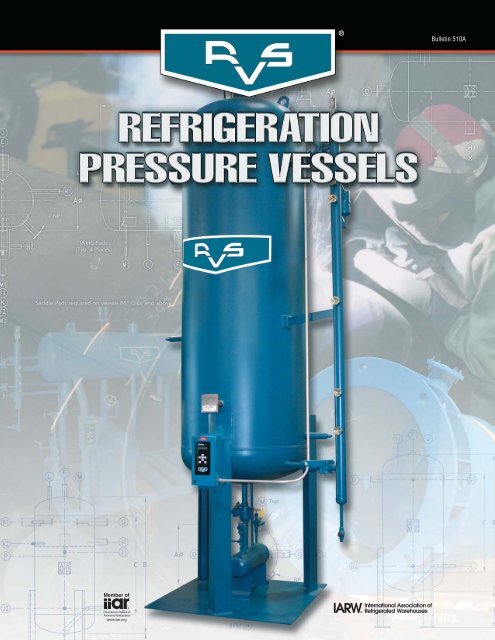
Bulletin 510A
RVS Corporation Manufacturing Facility, Bryan, TX.<br />
● RVS Corporation–Founded in 1983.<br />
®<br />
● Over 100 years of <strong>Engineering</strong> experience in pressure vessel and<br />
heat exchanger design and manufacturing for the Food &<br />
Beverage, Petrochemical and Industrial Process markets.<br />
● Plate thickness from 1/4" to 3" (to ASME Section VIII, Division 1).<br />
● Capable of manufacturing 6" to 180" diameter pressure vessels.<br />
● Quality products with fast, on-time shipments typically 4 to 8<br />
weeks after drawing approval.<br />
● 50,000 sq. ft. manufacturing facility.<br />
● State-of-the-art CNC plasma cutting table for customers who<br />
demand precision manufacturing.<br />
● Six (6) overhead c ranes<br />
capable of hoisting vessels up<br />
to 100,000 lbs.<br />
● Production capacity includes<br />
16 vessel welding stations<br />
utilizing multiple shifts to meet<br />
the most demanding delivery<br />
schedules.<br />
Refrigeration <strong>Pressure</strong> <strong>Vessel</strong>s<br />
In most industrial refrigeration systems, individual pressure vessels<br />
often require custom design features. At RVS, we design and manufacture<br />
pressure vessels to meet your specific requirements. RVS<br />
products are assembled by a dedicated and highly experienced workforce<br />
utilizing the latest and most highly technical equipment available.<br />
A knowledgeable marketing team with refrigeration systems<br />
experience is dedicated to providing rapid price quotations, quick<br />
drawing submittals, and accurate technical support. The end result is<br />
FAST, ON-TIME shipments.<br />
All vessel design and construction is in accordance with the latest<br />
version of the ASME Boiler and <strong>Pressure</strong> <strong>Vessel</strong> Code, Section VIII,<br />
Division 1. <strong>Vessel</strong> nozzles are in accordance with ASME B31.5.<br />
Custom Designed & Manufactured • Superior Quali<br />
©2010 EVAPCO, Inc.
ty • Proven Performance • Fast, On-Time Shipments<br />
<strong>Pressure</strong> <strong>Vessel</strong> Fabrication Capabilities<br />
60” Dia. x 60’ 0” Vertical Still <strong>Vessel</strong> 48” Dia. x 8’ 0” Vertical Reflux Accumulator 36” Dia. x 52’ 0” Vertical Amine Contactor<br />
72” Dia. x 24’ 0” Horizontal Flash Receiver 108” Dia. x 45’ 0” Horizontal R-134A Receiver Assembling removable ‘U’ tube bundles for<br />
‘BJU’ Type Shell & Tube Heat Exchangers.<br />
CNC Plasma Cutting Table Submerged Arc Welder<br />
Plate Bending Rolls<br />
Low temperature refrigeration skid package.<br />
n-house capabilities including<br />
sandblasting, painting, piping and<br />
complete electrical wiring allow us to<br />
provide customers with a finished<br />
product ready for installation at the<br />
jobsite without the additional time and<br />
expense of shipping it to a subcontractor.<br />
All piping systems are designed and<br />
fabricated to the requirements of ASME<br />
Standard B31.3 for Process Piping and<br />
B31.5 for Refrigeration Piping.<br />
3<br />
Separator vessel with pumps and controls.<br />
®
Horizontal High <strong>Pressure</strong> Receivers 250# DWP<br />
NP<br />
12”<br />
A B C D E F G H J K X (lbs.) (Ft3 ) (lbs. @ 80%)<br />
Overall Shell Liquid Liquid Level <strong>Vessel</strong> Internal Pumpdown<br />
Model No. Diameter Length Length Inlet Outlet Equalizer Column Purge Relief Drain Saddles Weight Volume Capacity<br />
HHPR20-96 20 96 81 1-1/4 1 3/4 1-1/4 3/4 1/2 3/4 48 785 16.1 472<br />
HHPR20-144 20 144 129 1-1/2 1 1 1-1/4 3/4 1/2 3/4 86 1,100 23.7 695<br />
HHPR24-144 24 144 127-1/2 2 1-1/4 1 1-1/4 3/4 1/2 3/4 86 1,330 34.9 1,023<br />
HHPR24-192 24 192 175-1/2 2 1-1/4 1-1/4 1-1/4 3/4 1/2 3/4 116 1,750 47.3 1,387<br />
HHPR30-138 30 138 119 2 1-1/4 1-1/4 1-1/4 3/4 1/2 3/4 80 1,625 51.0 1,496<br />
HHPR36-141 36 141 119 2-1/2 1-1/2 1-1/2 1-1/4 3/4 1/2 3/4 83 2,015 75.7 2,220<br />
HHPR42-144 42 144 119 3 2 2 1-1/4 3/4 3/4 3/4 72 2,425 105 3,080<br />
HHPR48-147 48 147 119 3 2 2 1-1/4 3/4 3/4 3/4 74 2,860 139 4,077<br />
HHPR48-266 48 266 238 4 2-1/2 2-1/2 1-1/4 3/4 3/4 3/4 158 4,980 266 7,803<br />
HHPR54-150 54 150 119 4 2-1/2 2-1/2 1-1/4 3/4 3/4 3/4 75 4,395 185 5,427<br />
HHPR54-269 54 269 238 5 3 3 1-1/4 3/4 1 3/4 161 7,565 339 9,944<br />
HHPR60-153 60 153 119 4 2-1/2 2-1/2 1-1/4 3/4 1 3/4 77 5,025 231 6,776<br />
HHPR60-272 60 272 238 5 3 3 1-1/4 3/4 1 3/4 162 8,550 421 12,350<br />
HHPR72-159 72 159 119 5 3 3 1-1/4 3/4 1 3/4 80 8,020 343 10,062<br />
HHPR72-278 72 278 238 6 4 4 1-1/4 3/4 1 3/4 166 13,250 617 18,100<br />
HHPR84-165 84 165 119 5 4 4 1-1/4 3/4 1 3/4 74 9,820 478 14,022<br />
HHPR84-284 84 284 238 6 5 5 1-1/4 3/4 1 3/4 168 15,960 853 25,023<br />
HHPR96-171 96 171 119 6 4 4 1-1/4 3/4 1 3/4 73 12,675 646 18,951<br />
HHPR96-290 96 290 238 8 5 5 1-1/4 3/4 1-1/4 3/4 176 19,750 1,131 33,179<br />
HHPR108-177 108 177 119 6 5 5 1-1/4 3/4 1 3/4 65 16,610 826 24,231<br />
HHPR108-296 108 296 238 8 6 6 1-1/4 3/4 1-1/4 3/4 170 26,150 1,462 42,889<br />
HHPR120-183 120 183 119 8 5 5 1-1/4 3/4 1-1/4 3/4 65 25,600 1,046 30,685<br />
HHPR120-302 120 302 238 10 6 6 1-1/4 3/4 1-1/4 3/4 170 39,700 1,831 53,714<br />
HHPR144-195 144 195 119 10 6 6 1-1/4 3/4 1-1/4 3/4 65 35,200 1,583 46,438<br />
HHPR144-314 144 314 238 12 6 6 1-1/4 3/4 1-1/4 3/4 170 51,900 2,714 79,617<br />
Notes: All dimensions are given in inches.<br />
Pumpdown capacity is given in lbs of R-717 at 80% full and +95°F<br />
Consult factory for certified drawings.<br />
4<br />
B<br />
C<br />
X
Vertical High <strong>Pressure</strong> Receivers 250# DWP<br />
Notes: All dimensions are given in inches.<br />
Pumpdown capacity is given in lbs of R-717 at 80% full and +95°F<br />
Consult factory for certified drawings.<br />
C B<br />
18”<br />
5<br />
Top Top Top<br />
BTM<br />
NP<br />
4 Legs required on vessels 84” O.D. and above.<br />
A B C D E F G H J K (lbs.) (Ft3 ) (lbs. @ 80%)<br />
Overall Shell Liquid Liquid Level <strong>Vessel</strong> Internal Pumpdown<br />
Model No. Diameter Length Length Inlet Outlet Equalizer Column Purge Relief Drain Weight Volume Capacity<br />
VHPR20-144 20 144 129 1-1/2 1 1 1-1/4 3/4 1/2 3/4 1,090 23.7 695<br />
VHPR24-144 24 144 127-1/2 2 1-1/4 1 1-1/4 3/4 1/2 3/4 1,330 34.9 1,023<br />
VHPR30-138 30 138 119 2 1-1/4 1-1/4 1-1/4 3/4 1/2 3/4 1,625 51.0 1,496<br />
VHPR36-141 36 141 119 2-1/2 1-1/2 1-1/4 1-1/4 3/4 1/2 3/4 2,015 75.7 2,220<br />
VHPR42-144 42 144 119 3 2 2 1-1/4 3/4 3/4 3/4 2,425 105 3,080<br />
VHPR48-147 48 147 119 3 2 2 1-1/4 3/4 3/4 3/4 2,860 139 4,077<br />
VHPR48-195 48 195 167 4 2 2 1-1/4 3/4 3/4 3/4 3,650 192 5,633<br />
VHPR54-150 54 150 119 4 2 2 1-1/4 3/4 3/4 3/4 4,395 185 5,427<br />
VHPR54-198 54 198 167 4 2-1/2 2-1/2 1-1/4 3/4 3/4 3/4 5,580 245 7,187<br />
VHPR60-153 60 153 119 4 2-1/2 2-1/2 1-1/4 3/4 1 3/4 5,025 231 6,776<br />
VHPR60-201 60 201 167 4 3 3 1-1/4 3/4 1 3/4 6,350 305 8,947<br />
VHPR72-159 72 159 119 5 3 3 1-1/4 3/4 1 3/4 8,020 343 10,062<br />
VHPR72-207 72 207 167 5 4 4 1-1/4 3/4 1 3/4 9,930 450 13,201<br />
VHPR84-165 84 165 119 5 4 4 1-1/4 3/4 1 3/4 9,820 478 14,022<br />
VHPR84-213 84 213 167 6 4 4 1-1/4 3/4 1 3/4 12,080 625 18,335<br />
VHPR96-171 96 171 119 6 4 4 1-1/4 3/4 1 3/4 12,675 646 18,951<br />
VHPR96-219 96 219 167 6 5 5 1-1/4 3/4 1 3/4 15,290 834 24,466<br />
VHPR108-177 108 177 119 6 5 5 1-1/4 3/4 1 3/4 16,610 826 24,231<br />
VHPR108-225 108 225 167 8 5 5 1-1/4 3/4 1-1/4 3/4 20,140 1,075 31,536<br />
VHPR120-183 120 183 119 8 5 5 1-1/4 3/4 1-1/4 3/4 25,600 1,046 30,685<br />
VHPR120-231 120 231 167 8 6 6 1-1/4 3/4 1-1/4 3/4 30,810 1,354 39,720<br />
VHPR144-195 144 195 119 10 6 6 1-1/4 3/4 1-1/4 3/4 35,200 1,583 46,438<br />
VHPR144-243 144 243 167 10 6 6 1-1/4 3/4 1-1/4 3/4 41,900 2,035 59,698
Vertical High <strong>Pressure</strong> / Thermosyphon Receivers 250# DWP<br />
C B<br />
Notes: All dimensions are given in inches.<br />
Pumpdown capacity (lower section) is given in lbs of R-717 at 100% full and +95°F<br />
Consult factory for certified drawings.<br />
18”<br />
6<br />
Top<br />
Top<br />
BTM<br />
Top<br />
NP<br />
4 Legs required on vessels 84” O.D. and above.<br />
A B C D E F G H J K L M N P (lbs.) (Ft 3 ) Lower (lbs. @ 100%) (Ft 3 ) Upper<br />
Overall Shell Liquid Liquid Thermo Thermo Level TS Level Thermo <strong>Vessel</strong> Internal Pumpdown Internal<br />
Model No. Diameter Length Length Inlet Outlet Equalizer Return Supply Column Column Purge Relief Drain Drain Weight Volume Capacity Volume<br />
VHP/TSR48-195 48 195 167 4 2 3 4 3 1-1/4 1 3/4 3/4 3/4 3/4 4,150 153 5,610 18<br />
VHP/TSR54-198 54 198 167 4 2-1/2 3 4 3 1-1/4 1 3/4 3/4 3/4 3/4 6,100 194 7,113 23<br />
VHP/TSR60-201 60 201 167 4 3 3 4 3 1-1/4 1 3/4 1 3/4 3/4 6,850 241 8,837 29<br />
VHP/TSR72-207 72 207 167 5 4 4 5 4 1-1/4 1 3/4 1 3/4 3/4 10,450 339 12,431 42<br />
VHP/TSR84-213 84 213 167 6 4 5 6 5 1-1/4 1 3/4 1 3/4 3/4 12,850 468 17,161 57<br />
VHP/TSR96-219 96 219 167 6 5 5 6 5 1-1/4 1 3/4 1 3/4 3/4 16,000 620 22,735 75<br />
VHP/TSR108-225 108 225 167 8 5 6 8 6 1-1/4 1 3/4 1-1/4 3/4 3/4 21,000 795 29,152 95<br />
VHP/TSR120-231 120 231 167 8 6 6 8 6 1-1/4 1 3/4 1-1/4 3/4 3/4 32,000 994 36,449 117<br />
VHP/TSR144-243 144 243 167 10 6 8 10 8 1-1/4 1 3/4 1-1/4 3/4 3/4 43,500 1,470 53,904 169
Horizontal Thermosyphon Receivers 250# DWP<br />
N.S.<br />
F.S.<br />
Notes: All dimensions are given in inches.<br />
Heat of rejection is given in MBH at +96°F<br />
Consult factory for certified drawings.<br />
NP<br />
7<br />
B<br />
C<br />
X<br />
Mounting Clips<br />
(Typ. 4 Places)<br />
Heat of A B C D E F G H J X (lbs.) (Ft 3 )<br />
Rejection Overall Shell Liquid Liquid Thermo Thermo <strong>Vessel</strong> Internal<br />
Model No. MBH Diameter Length Length Inlet Outlet Equalizer Return Supply Relief Supports Weight Volume<br />
HTSR8-48 113 8 48 40 1-1/2 1-1/2 1-1/4 1-1/4 1-1/4 1/2 22 150 1.0<br />
HTSR10-48 173 10 48 38 2 2 1-1/4 2 1-1/4 1/2 22 210 1.7<br />
HTSR12-48 244 12 48 37 2 2 1-1/2 2 1-1/2 1/2 22 270 2.6<br />
HTSR12-72 377 12 72 61 2-1/2 2-1/2 2 2-1/2 2 1/2 33 380 4.2<br />
HTSR16-72 619 16 72 59 3 3 2 3 2 1/2 32 490 7.4<br />
HTSR20-72 968 20 72 57 4 4 3 4 3 1/2 32 600 11.6<br />
HTSR24-72 1,405 24 72 55-1/2 4 4 3 4 3 1/2 32 740 16.3<br />
HTSR30-84 2,592 30 84 65 5 5 4 5 4 1/2 38 1,080 30.5<br />
HTSR36-96 4,303 36 96 74 8 8 6 6 6 1/2 48 1,400 50.7<br />
HTSR42-120 7,414 42 120 95 8 8 8 8 8 1/2 60 2,020 87.1<br />
HTSR48-147 11,900 48 147 119 10 10 10 10 10 1/2 72 2,830 142
Vertical Thermosyphon Receivers 250# DWP<br />
Mounting Clips<br />
(Typ. 2 Places)<br />
Notes: All dimensions are given in inches.<br />
Heat of rejection is given in MBH at +96°F<br />
Consult factory for certified drawings.<br />
C B<br />
Heat of A B C D E F G H J (lbs.) (Ft 3 )<br />
Rejection Overall Shell Liquid Liquid Thermo Thermo <strong>Vessel</strong> Internal<br />
Model No. MBH Diameter Length Length Inlet Outlet Equalizer Return Supply Relief Weight Volume<br />
VTSR8-48 203 8 48 40 2 2 1 1/4 2 1-1/4 1/2 155 1.0<br />
VTSR10-48 302 10 48 38 2-1/2 2-1/2 1 1/2 2 1-1/2 1/2 210 1.7<br />
VTSR12-48 422 12 48 37 2-1/2 2-1/2 2 2-1/2 2 1/2 270 2.6<br />
VTSR12-72 709 12 72 61 3 3 2-1/2 3 2-1/2 1/2 380 4.2<br />
VTSR16-72 1,111 16 72 59 4 4 3 4 3 1/2 490 7.4<br />
VTSR20-72 1,653 20 72 57 5 5 4 4 4 1/2 630 11.6<br />
VTSR24-72 2,148 24 72 55-1/2 5 5 4 5 4 1/2 760 16.3<br />
VTSR30-84 4,096 30 84 65 6 6 5 6 5 1/2 1,085 30.5<br />
8<br />
BTM<br />
Top<br />
Top<br />
NP
Vertical Control <strong>Pressure</strong> Receivers 250# DWP<br />
Lift Lugs<br />
Notes: All dimensions are given in inches.<br />
Pumpdown capacity is given in lbs of R-717 at 80% full and +60°F<br />
Consult factory for certified drawings.<br />
C B<br />
18”<br />
9<br />
Top<br />
BTM<br />
Top<br />
NP<br />
4 Legs required on vessels 84” O.D. and above.<br />
A B C D E F G H J K L (lbs.) (Ft 3 ) (lbs. @ 80%)<br />
Overall Shell Liquid Liquid Liquid Gas Level Oil Pot <strong>Vessel</strong> Internal Pumpdown<br />
Model No. Diameter Length Length Transfer Inlet Outlet Inlet Inlet/Outlet Column Relief Vent Drain Weight Volume Capacity<br />
VCPR20-144 20 144 129 1-1/4 1-1/4 3/4 3/4 1-1/4 1-1/2 3/4 2 1,090 23.7 729<br />
VCPR24-144 24 144 127-1/2 1-1/4 1-1/4 1 3/4 1-1/4 1-1/2 3/4 2 1,330 34.9 1,074<br />
VCPR30-138 30 138 119 2 1-1/2 1-1/4 3/4 1-1/4 1-1/2 3/4 2 1,625 51.0 1,570<br />
VCPR36-141 36 141 119 2 2 1-1/4 3/4 1-1/4 1-1/2 3/4 2 2,015 75.7 2,331<br />
VCPR42-144 42 144 119 2 2 1-1/2 3/4 1-1/4 1-1/2 3/4 2 2,425 105 3,234<br />
VCPR48-147 48 147 119 3 2-1/2 2 1-1/4 1-1/4 1-1/2 3/4 2 2,860 139 4,281<br />
VCPR54-150 54 150 119 4 3 2 1-1/4 1-1/4 1-1/2 3/4 2 4,395 185 5,698<br />
VCPR60-153 60 153 119 4 3 2 1-1/4 1-1/4 1-1/2 3/4 2 5,025 231 7,114<br />
VCPR72-159 72 159 119 5 4 2-1/2 1-1/2 1-1/4 1-1/2 3/4 2 8,020 343 10,564<br />
VCPR84-165 84 165 119 5 4 3 2 1-1/4 1-1/2 3/4 2 9,820 478 14,722<br />
VCPR96-171 96 171 119 5 4 3 2 1-1/4 1-1/2 3/4 2 12,675 646 19,896
Vertical Pilot Receivers 250# DWP<br />
Notes: All dimensions are given in inches.<br />
Consult factory for certified drawings.<br />
C B<br />
12”<br />
10<br />
BTM<br />
Top Top<br />
A B C D E F G H J (lbs.) (Ft 3 )<br />
Overall Shell Liquid Liquid Chamber <strong>Vessel</strong> Internal<br />
Model No. Diameter Length Length Inlet Outlet Vent Balance Drain Relief Weight Volume<br />
VPR10-48 10 48 38 2 1 1-1/4 3/4 1/2 1/2 205 1.7<br />
VPR12-48 12 48 37 3 1-1/2 2 3/4 1/2 1/2 250 2.6<br />
VPR16-60 16 60 47 4 2 2-1/2 3/4 1/2 1/2 400 6.0<br />
VPR20-60 20 60 45 6 3 4 3/4 1/2 1/2 500 9.4<br />
VPR24-72 24 72 55-1/2 8 4 5 3/4 1/2 1/2 720 16.3<br />
NP
Vertical Recirculators 250# DWP<br />
B C<br />
S<br />
Lift Lugs<br />
F.S.<br />
N.S.<br />
Notes: All dimensions are given in inches.<br />
Consult factory for certified drawings.<br />
See RVS Bulletin 506 MRP Matrix Recirculator Package for capacities.<br />
11<br />
BTM<br />
BTM<br />
BTM<br />
BTM<br />
BTM CTR<br />
NP<br />
BTM<br />
4 Legs required on vessels 84” O.D. and above.<br />
A B C D E F G H J K L M N S (lbs.)<br />
Overall Shell Suction Gas Pump Liquid Level Minimum Motor Oil Pot Leg <strong>Vessel</strong><br />
Model No. Diameter Length Length Inlet Outlet Suction(s) Make Up Column Relief Drain Flow Cooling Vent Height Weight<br />
VR24-112 24 112-1/2 96 5 4 4 1-1/4 1-1/2 1-1/2 2 1-1/4 3/4 3/4 58 1,290<br />
VR30-115 30 115 96 6 5 4 1-1/4 1-1/2 1-1/2 2 1-1/4 3/4 3/4 60 1,610<br />
VR36-118 36 118 96 6 6 4 1-1/2 1-1/2 1-1/2 2 1-1/4 3/4 3/4 60 1,960<br />
VR42-144 42 144 119 8 6 4 2 1-1/2 1-1/2 2 1-1/4 3/4 3/4 60 2,720<br />
VR48-147 48 147 119 8 8 5 2 1-1/2 1-1/2 2 1-1/2 3/4 3/4 64 3,160<br />
VR54-150 54 150 119 10 8 5 2 1-1/2 1-1/2 2 1-1/2 3/4 3/4 64 4,750<br />
VR60-153 60 153 119 10 8 6 2-1/2 1-1/2 1-1/2 2 1-1/2 3/4 3/4 64 5,400<br />
VR72-159 72 159 119 12 10 6 3 1-1/2 1-1/2 2 1-1/2 3/4 3/4 72 8,450<br />
VR84-165 84 165 119 12 10 8 3 1-1/2 1-1/2 2 1-1/2 3/4 3/4 72 10,325<br />
VR96-171 96 171 119 14 12 8 4 1-1/2 1-1/2 2 1-1/2 3/4 3/4 72 13,325<br />
VR108-177 108 177 119 16 12 (3) 6 4 1-1/2 1-1/2 2 3 (3) 3/4 3/4 72 17,390<br />
VR120-183 120 183 119 16 14 (3) 8 4 1-1/2 1-1/2 2 3 (3) 3/4 3/4 72 26,700<br />
VR144-195 144 195 119 20 16 (4) 8 5 1-1/2 1-1/2 2 4 (4) 3/4 3/4 72 36,950
Horizontal Recirculators 250# DWP<br />
NP<br />
Weld Pads<br />
(Typ. 4 Places)<br />
Notes: All dimensions are given in inches.<br />
Consult factory for certified drawings.<br />
See RVS Bulletin 506 MRP Matrix Recirculator Package for capacities.<br />
12<br />
Lift Lugs<br />
Saddle Pads required on vessels 84” O.D. and above.<br />
A B C D E F G H J K L M N (lbs.)<br />
Overall Shell Suction Gas Pump Liquid Level Minimum Motor Oil Pot <strong>Vessel</strong><br />
Model No. Diameter Length Length Inlet Outlet Suction(s) Make Up Column Relief Drain Flow Cooling Vent Weight<br />
HR24-135 24 135-1/2 119 4 4 4 1 1-1/2 1-1/2 2 1-1/4 3/4 3/4 1,300<br />
HR30-138 30 138 119 5 5 4 1-1/4 1-1/2 1-1/2 2 1-1/4 3/4 3/4 1,690<br />
HR36-141 36 141 119 6 5 4 1-1/2 1-1/2 1-1/2 2 1-1/4 3/4 3/4 2,095<br />
HR42-144 42 144 119 8 6 4 2 1-1/2 1-1/2 2 1-1/4 3/4 3/4 2,520<br />
HR48-147 48 147 119 8 8 5 2 1-1/2 1-1/2 2 1-1/2 3/4 3/4 2,975<br />
HR54-150 54 150 119 8 8 5 2 1-1/2 1-1/2 2 1-1/2 3/4 3/4 4,570<br />
HR60-153 60 153 119 10 8 6 2-1/2 1-1/2 1-1/2 2 1-1/2 3/4 3/4 5,225<br />
HR72-159 72 159 119 10 10 6 2-1/2 1-1/2 1-1/2 2 1-1/2 3/4 3/4 8,340<br />
HR84-165 84 165 119 12 10 8 3 1-1/2 1-1/2 2 1-1/2 3/4 3/4 10,210<br />
HR96-171 96 171 119 14 12 8 3 1-1/2 1-1/2 2 1-1/2 3/4 3/4 13,180<br />
HR108-177 108 177 119 16 12 (3) 6 4 1-1/2 1-1/2 2 3 (3) 3/4 3/4 17,275<br />
HR120-183 120 183 119 16 14 (3) 8 4 1-1/2 1-1/2 2 3 (3) 3/4 3/4 26,625<br />
HR144-195 144 195 119 20 16 (4) 8 5 1-1/2 1-1/2 2 4 (3) 3/4 3/4 36,535<br />
F.S.<br />
B<br />
C
Vertical Intercoolers 250# DWP<br />
Lift Lugs<br />
Booster<br />
Discharge box<br />
C B<br />
42”<br />
13<br />
Top Top<br />
BTM<br />
BTM<br />
NP<br />
4 Legs required on vessels 84” O.D. and above.<br />
A B C D E F G H J K L (lbs.)<br />
Overall Shell Booster Gas Liquid Liquid Level Oil Pot <strong>Vessel</strong><br />
Model No. Diameter Length Length Inlet Outlet Make-Up Outlet Column Relief Drain Vent Weight<br />
VI16-96 16 96 83 3 3 1 1 1-1/2 1-1/2 2 3/4 650<br />
VI20-108 20 108 93 3 3 1 1 1-1/2 1-1/2 2 3/4 910<br />
VI24-112 24 112-1/2 96 4 4 1 1 1-1/2 1-1/2 2 3/4 1,150<br />
VI30-115 30 115 96 5 5 1-1/4 1-1/4 1-1/2 1-1/2 2 3/4 1,475<br />
VI36-118 36 118 96 6 6 1-1/2 1-1/2 1-1/2 1-1/2 2 3/4 1,835<br />
VI42-144 42 144 119 6 6 2 2 1-1/2 1-1/2 2 3/4 2,750<br />
VI48-147 48 147 119 8 8 2 2 1-1/2 1-1/2 2 3/4 2,975<br />
VI54-150 54 150 119 8 8 2 2 1-1/2 1-1/2 2 3/4 4,750<br />
VI60-153 60 153 119 8 8 2-1/2 2-1/2 1-1/2 1-1/2 2 3/4 5,430<br />
VI72-159 72 159 119 10 10 3 3 1-1/2 1-1/2 2 3/4 8,600<br />
VI84-165 84 165 119 10 10 3 3 1-1/2 1-1/2 2 3/4 10,575<br />
VI96-171 96 171 119 12 12 4 4 1-1/2 1-1/2 2 3/4 13,700<br />
VI108-177 108 177 119 12 12 4 4 1-1/2 1-1/2 2 3/4 17,950<br />
VI120-183 120 183 119 14 14 4 4 1-1/2 1-1/2 2 3/4 27,650<br />
VI144-195 144 195 119 16 16 5 5 1-1/2 1-1/2 2 3/4 38,325<br />
Notes: All dimensions are given in inches.<br />
Consult factory for certified drawings.<br />
See RVS Bulletin 510 MVI Intercooler Package for capacities.
Vertical Intercoolers with Coil 250# DWP<br />
3”<br />
N<br />
Lift Lugs<br />
Notes: All dimensions are given in inches.<br />
Consult factory for certified drawings.<br />
See RVS Bulletin 510 MVI Intercooler Package for capacities.<br />
Coil<br />
Booster<br />
Discharge box<br />
C B<br />
42”<br />
14<br />
Top<br />
Top<br />
BTM BTM<br />
NP<br />
4 Legs required on vessels 84” O.D. and above.<br />
A B C D E F G H J K L (feet) M N (lbs.)<br />
Overall Shell Booster Gas Liquid Liquid Level Oil Pot Coil Coil Coil <strong>Vessel</strong><br />
Model No. Diameter Length Length Inlet Outlet Make-Up Outlet Column Relief Drain Vent Linear Feet In/Out Height Weight<br />
VIC16-96 16 96 83 3 3 1 1 1-1/2 1-1/2 2 3/4 75 3/4 28 785<br />
VIC20-108 20 108 93 3 3 1 1 1-1/2 1-1/2 2 3/4 116 3/4 20 1,130<br />
VIC24-112 24 112-1/2 96 4 4 1 1 1-1/2 1-1/2 2 3/4 139 1 30 1,515<br />
VIC30-115 30 115 96 5 5 1-1/4 1-1/4 1-1/2 1-1/2 2 3/4 173 1-1/4 30 2,090<br />
VIC36-118 36 118 96 6 6 1-1/2 1-1/2 1-1/2 1-1/2 2 3/4 220 1-1/2 36 2,535<br />
VIC42-144 42 144 119 6 6 2 2 1-1/2 1-1/2 2 3/4 294 1-1/2 38 3,700<br />
VIC48-147 48 147 119 8 8 2 2 1-1/2 1-1/2 2 3/4 385 1-1/2 30 4,215<br />
VIC54-150 54 150 119 8 8 2 2 1-1/2 1-1/2 2 3/4 395 2 36 6,500<br />
VIC60-153 60 153 119 8 8 2-1/2 2-1/2 1-1/2 1-1/2 2 3/4 491 2 36 7,690<br />
VIC72-159 72 159 119 10 10 3 3 1-1/2 1-1/2 2 3/4 630 3 36 11,425<br />
VIC84-165 84 165 119 10 10 3 3 1-1/2 1-1/2 2 3/4 857 3 42 14,465<br />
VIC96-171 96 171 119 12 12 4 4 1-1/2 1-1/2 2 3/4 1,128 4 36 18,700<br />
VIC108-177 108 177 119 12 12 4 4 1-1/2 1-1/2 2 3/4 1,424 4 42 24,270<br />
VIC120-183 120 183 119 14 14 4 4 1-1/2 1-1/2 2 3/4 1,758 5 48 35,450<br />
VIC144-195 144 195 119 16 16 5 5 1-1/2 1-1/2 2 3/4 2,471 6 42 49,295
Horizontal Accumulators 250# DWP<br />
F.S.<br />
NP<br />
Weld Pads<br />
(Typ. 4 Places)<br />
Saddle Pads required on vessels 84” O.D. and above.<br />
15<br />
@315°<br />
F.S.<br />
@270°<br />
Lift Lugs<br />
A B C D E F G H J K L (lbs.)<br />
Overall Shell Suction Gas Liquid Level 3 Way Oil Pot <strong>Vessel</strong><br />
Model No. Diameter Length Length Inlet Outlet Outlet(s) Column Relief Drain Vent(s) Vent Weight<br />
HA24-135 24 135-1/2 119 4 4 3 1-1/2 1-1/2 2 1-1/4 3/4 1,250<br />
HA30-138 30 138 119 5 5 3 1-1/2 1-1/2 2 1-1/4 3/4 1,625<br />
HA36-141 36 141 119 6 5 4 1-1/2 1-1/2 2 1-1/4 3/4 2,015<br />
HA42-144 42 144 119 8 6 4 1-1/2 1-1/2 2 1-1/4 3/4 2,425<br />
HA48-147 48 147 119 8 8 4 1-1/2 1-1/2 2 1-1/4 3/4 2,860<br />
HA54-150 54 150 119 8 8 4 1-1/2 1-1/2 2 1-1/4 3/4 4,395<br />
HA60-153 60 153 119 10 8 (2) 4 1-1/2 1-1/2 2 (2) 1-1/4 3/4 5,025<br />
HA72-159 72 159 119 10 10 (2) 4 1-1/2 1-1/2 2 (2) 1-1/4 3/4 8,020<br />
HA84-165 84 165 119 12 10 (2) 4 1-1/2 1-1/2 2 (2) 1-1/4 3/4 9,820<br />
HA96-171 96 171 119 14 12 (2) 4 1-1/2 1-1/2 2 (2) 1-1/4 3/4 12,675<br />
HA108-177 108 177 119 16 12 (2) 4 1-1/2 1-1/2 2 (2) 1-1/4 3/4 16,610<br />
HA120-183 120 183 119 16 14 (2) 4 1-1/2 1-1/2 2 (2) 1-1/4 3/4 25,600<br />
HA144-195 144 195 119 20 16 (2) 4 1-1/2 1-1/2 2 (2) 1-1/4 3/4 35,130<br />
Notes: All dimensions are given in inches.<br />
Consult factory for certified drawings.<br />
Horizontal Accumulator Capacity–Tons of Refrigeration R-717<br />
Evaporator Temperature °F<br />
Single Stage* Two Stage*<br />
Model No. 30°F 20°F 10°F 0°F -10°F -20°F -20°F -30°F -40°F -50°F<br />
HA24-135 112 102 91 81 70 62 73 62 53 45<br />
HA30-138 187 171 152 136 118 104 122 104 89 75<br />
HA36-141 278 255 227 202 176 154 182 156 133 112<br />
HA42-144 386 354 315 281 245 215 253 217 185 157<br />
HA48-147 513 470 418 373 325 285 336 288 246 208<br />
HA54-150 693 636 565 504 439 386 454 389 332 282<br />
HA60-153 864 793 705 628 548 481 566 485 414 351<br />
HA72-159 1267 1162 1033 921 802 705 829 710 607 515<br />
HA84-165 1742 1598 1421 1266 1103 969 1140 976 834 707<br />
HA96-171 2297 2107 1874 1670 1455 1277 1503 1287 1100 933<br />
HA108-177 2924 2682 2385 2125 1852 1625 1914 1638 1400 1187<br />
HA120-183 3626 3326 2958 2636 2296 2016 2373 2032 1736 1472<br />
HA144-195 5264 4828 4293 3826 3334 2926 3445 2949 2520 2136<br />
* Single stage capacities based on +96°F liquid supply temperature.<br />
** Two stage capacities based on +25°F liquid supply temperature.
Vertical Accumulators 250# DWP<br />
Lift Lugs<br />
C B<br />
36”<br />
16<br />
NP<br />
Top<br />
BTM BTM<br />
4 Legs required on vessels 84” O.D. and above.<br />
A B C D E F G H J K L (lbs.)<br />
Overall Shell Suction Gas Liquid Level 3 Way Oil Pot <strong>Vessel</strong><br />
Model No. Diameter Length Length Inlet Outlet Outlet(s) Column Relief Drain Vent(s) Vent Weight<br />
VA12-72 12 72 61 2-1/2 2-1/2 2 1-1/2 1-1/2 2 3/4 3/4 350<br />
VA16-85 16 85 72 3 3 2 1-1/2 1-1/2 2 3/4 3/4 550<br />
VA20-87 20 87 72 4 4 3 1-1/2 1-1/2 2 3/4 3/4 710<br />
VA24-88 24 88-1/2 72 5 4 3 1-1/2 1-1/2 2 1-1/4 3/4 875<br />
VA30-115 30 115 96 6 5 3 1-1/2 1-1/2 2 1-1/4 3/4 1,410<br />
VA36-118 36 118 96 6 6 4 1-1/2 1-1/2 2 1-1/4 3/4 1,760<br />
VA42-121 42 121 96 8 6 4 1-1/2 1-1/2 2 1-1/4 3/4 2,150<br />
VA48-147 48 147 119 8 8 4 1-1/2 1-1/2 2 1-1/4 3/4 2,960<br />
VA54-150 54 150 119 10 8 4 1-1/2 1-1/2 2 1-1/4 3/4 4,550<br />
VA60-153 60 153 119 10 8 (2) 4 1-1/2 1-1/2 2 (2) 1-1/4 3/4 5,200<br />
VA72-159 72 159 119 12 10 (2) 4 1-1/2 1-1/2 2 (2) 1-1/4 3/4 8,250<br />
VA84-165 84 165 119 12 10 (2) 4 1-1/2 1-1/2 2 (2) 1-1/4 3/4 10,125<br />
VA96-171 96 171 119 14 12 (2) 4 1-1/2 1-1/2 2 (2) 1-1/4 3/4 13,125<br />
VA108-177 108 177 119 16 12 (2) 4 1-1/2 1-1/2 2 (2) 1-1/4 3/4 17,190<br />
VA120-183 120 183 119 16 14 (2) 4 1-1/2 1-1/2 2 (2) 1-1/4 3/4 26,500<br />
VA144-195 144 195 119 20 16 (2) 4 1-1/2 1-1/2 2 (2) 1-1/4 3/4 36,725<br />
Notes: All dimensions are given in inches. Consult factory for certified drawings.<br />
Vertical Accumulator Capacity–Tons of Refrigeration R-717<br />
Evaporator Temperature °F<br />
Single Stage* Two Stage*<br />
Model No. 30°F 20°F 10°F 0°F -10°F -20°F -20°F -30°F -40°F -50°F<br />
VA12-72 35 32 29 25 22 19 23 19 16 14<br />
VA16-85 64 58 52 46 40 35 41 35 30 25<br />
VA20-87 101 92 83 73 64 56 66 56 47 40<br />
VA24-88 147 135 120 107 93 82 96 82 70 59<br />
VA30-115 232 212 189 168 147 129 152 130 111 94<br />
VA36-118 333 305 271 242 211 185 218 187 159 135<br />
VA42-121 452 415 369 329 287 252 296 254 217 184<br />
VA48-147 590 541 481 429 374 328 387 331 283 240<br />
VA54-150 750 688 612 545 475 417 491 420 359 305<br />
VA60-153 925 848 754 672 586 514 606 519 443 376<br />
VA72-159 1339 1228 1092 974 848 745 877 751 642 544<br />
VA84-165 1819 1668 1484 1322 1115 1012 1191 1019 871 739<br />
VA96-171 2385 2187 1945 1734 1510 1326 1561 1336 1142 968<br />
VA108-177 3013 2764 2458 2190 1908 1675 1972 1688 1443 1223<br />
VA120-183 3715 3407 3030 2700 2350 2065 2431 2081 1779 1508<br />
VA144-195 5358 4914 4370 3894 3393 2978 3506 3002 2565 2174<br />
* Single stage capacities based on +96°F liquid supply temperature.<br />
** Two stage capacities based on +25°F liquid supply temperature.
Vertical Accumulators with Coil 250# DWP<br />
Lift Lugs<br />
3”<br />
Notes: All dimensions are given in inches.<br />
Consult factory for certified drawings.<br />
L<br />
Coil<br />
C B<br />
36”<br />
17<br />
NP<br />
Top BTM<br />
BTM<br />
4 Legs required on vessels 84” O.D. and above.<br />
A B C D E F G H J (feet) K L (lbs.)<br />
Overall Shell Suction Gas Level Oil Pot Coil Coil Coil <strong>Vessel</strong><br />
Model No. Diameter Length Length Inlet Outlet Column Relief Drain Vent Linear Feet In/Out Height Weight<br />
VAC16-85 16 85 72 3 3 1-1/2 1-1/2 2 3/4 56 3/4 22 650<br />
VAC20-87 20 87 72 4 4 1-1/2 1-1/2 2 3/4 71 1 25 890<br />
VAC24-88 24 88-1/2 72 5 4 1-1/2 1-1/2 2 3/4 81 1-1/4 34 1,155<br />
VAC30-115 30 115 96 6 5 1-1/2 1-1/2 2 3/4 128 1-1/4 38 1,860<br />
VAC36-118 36 118 96 6 6 1-1/2 1-1/2 2 3/4 160 1-1/2 42 2,435<br />
VAC42-121 42 121 96 8 6 1-1/2 1-1/2 2 3/4 218 1-1/2 34 3,060<br />
VAC48-147 48 147 119 8 8 1-1/2 1-1/2 2 3/4 227 2 30 3,910<br />
VAC54-150 54 150 119 10 8 1-1/2 1-1/2 2 3/4 289 2 36 5,765<br />
VAC60-153 60 153 119 10 8 1-1/2 1-1/2 2 3/4 356 2 36 6,695<br />
VAC72-159 72 159 119 12 10 1-1/2 1-1/2 2 3/4 516 3 34 10,445<br />
VAC84-165 84 165 119 12 10 1-1/2 1-1/2 2 3/4 700 3 36 13,105<br />
VAC96-171 96 171 119 14 12 1-1/2 1-1/2 2 3/4 918 4 40 17,035<br />
VAC108-177 108 177 119 16 12 1-1/2 1-1/2 2 3/4 1,159 4 36 22,125<br />
VAC120-183 120 183 119 16 14 1-1/2 1-1/2 2 3/4 1,429 5 36 32,580<br />
VAC144-195 144 195 119 20 16 1-1/2 1-1/2 2 3/4 2,061 6 36 45,495
Vertical Surge Drums 250# DWP<br />
Mounting Clips<br />
(Typ. 2 Places)<br />
Notes: All dimensions are given in inches.<br />
Surge volume calculated between 6" OPL and HLCO 6" below suction inlet elbow.<br />
Consult factory for certified drawings.<br />
Vertical Surge Drum Capacity–Tons of Refrigeration R-717<br />
Evaporator Temperature °F<br />
Single Stage* Two Stage*<br />
Model No. 30°F 20°F 10°F 0°F -10°F -20°F -20°F -30°F -40°F -50°F<br />
VSD12-48 35 32 29 25 22 19 23 19 16 14<br />
VSD16-54 64 58 52 46 40 35 41 35 30 25<br />
VSD20-60 101 92 83 73 64 56 66 56 47 40<br />
VSD24-60 147 135 120 107 93 82 96 82 70 59<br />
VSD30-72 232 212 189 168 147 129 152 130 111 94<br />
VSD36-78 333 305 271 242 211 185 218 187 159 135<br />
VSD42-84 452 415 369 329 287 252 296 254 217 184<br />
* Single stage capacities based on +96°F liquid supply temperature.<br />
** Two stage capacities based on +25°F liquid supply temperature.<br />
C B<br />
A B C D E F G H J (Ft 3 ) (lbs.)<br />
Overall Shell Suction Gas Liquid Liquid Level Surge <strong>Vessel</strong><br />
Model No. Diameter Length Length Inlet Outlet Outlet Make-Up Column Relief Volume Weight<br />
VSD12-48 12 48 37 2-1/2 2 2-1/2 3/4 1-1/2 1-1/2 1.3 250<br />
VSD16-54 16 54 41 3 2-1/2 3 3/4 1-1/2 1-1/2 2.8 370<br />
VSD20-60 20 60 45 4 3 4 1 1-1/2 1-1/2 5.1 525<br />
VSD24-60 24 60 43-1/2 5 4 5 1-1/4 1-1/2 1-1/2 6.8 600<br />
VSD30-72 30 72 53 6 4 6 1-1/2 1-1/2 1-1/2 14 935<br />
VSD36-78 36 78 56 8 5 8 2 1-1/2 1-1/2 22 1,200<br />
VSD42-84 42 84 59 8 6 8 2 1-1/2 1-1/2 30 1,560<br />
18<br />
Top<br />
BTM<br />
NP
Horizontal Surge Drums 250# DWP<br />
Notes: All dimensions are given in inches.<br />
Surge volume calculated between 4" OPL and HLCO 2" above center line.<br />
Consult factory for certified drawings.<br />
Horizontal Surge Drum Capacity–Tons of Refrigeration R-717<br />
NP<br />
Evaporator Temperature °F<br />
Single Stage* Two Stage*<br />
Model No. 30°F 20°F 10°F 0°F -10°F -20°F -20°F -30°F -40°F -50°F<br />
HSD12-48 9.1 8.3 7.4 6.6 5.7 5.0 5.9 5.0 4.2 3.6<br />
HSD16-60 20 18 16 14 13 11 13 11 9.6 8.0<br />
HSD20-72 36 33 29 26 22 19 23 20 17 14<br />
HSD24-72 56 51 46 40 35 31 36 31 26 22<br />
HSD30-96 94 86 77 68 59 51 61 52 44 37<br />
HSD36-96 139 127 114 101 88 77 90 77 65 55<br />
HSD42-120 194 177 159 141 123 107 126 108 91 76<br />
* Single stage capacities based on +96°F liquid supply temperature.<br />
** Two stage capacities based on +25°F liquid supply temperature.<br />
12<br />
Mounting Clips<br />
(Typ. 4 Places)<br />
A B C D E F G H J (Ft 3 ) (lbs.)<br />
Overall Shell Suction Gas Liquid Liquid Level Surge <strong>Vessel</strong><br />
Model No. Diameter Length Length Inlet Outlet Outlet Make-Up Column Relief Volume Weight<br />
HSD12-48 12 48 37 2-1/2 1-1/2 2-1/2 3/4 1-1/2 1-1/2 1.1 280<br />
HSD16-60 16 60 47 3 2 3 3/4 1-1/2 1-1/2 2.9 345<br />
HSD20-72 20 72 57 4 2-1/2 4 3/4 1-1/2 1-1/2 5.9 630<br />
HSD24-72 24 72 55-1/2 4 3 4 3/4 1-1/2 1-1/2 8.7 770<br />
HSD30-96 30 96 77 5 4 5 1-1/4 1-1/2 1-1/2 18 1,220<br />
HSD36-96 36 96 74 6 4 6 1-1/4 1-1/2 1-1/2 26 1,520<br />
HSD42-120 42 120 95 8 5 8 1-1/2 1-1/2 1-1/2 45 2,260<br />
19<br />
B<br />
C
Split Flow Horizontal Surge Drums 250# DWP<br />
Notes: All dimensions are given in inches.<br />
Surge volume calculated between 4" OPL and HLCO 2" above center line.<br />
Consult factory for certified drawings.<br />
Split Flow Horizontal Surge Drum Capacity–Tons of Refrigeration R-717<br />
Evaporator Temperature °F<br />
Single Stage* Two Stage*<br />
Model No. 30°F 20°F 10°F 0°F -10°F -20°F -20°F -30°F -40°F -50°F<br />
MHSD20-96 72 66 59 52 46 40 47 40 34 28<br />
MHSD24-96 112 102 91 81 70 62 73 62 53 45<br />
MHSD30-96 187 171 152 136 118 104 122 104 89 75<br />
MHSD36-96 278 255 227 202 176 154 182 156 133 112<br />
MHSD42-96 386 354 315 281 245 215 253 217 185 157<br />
MHSD48-120 513 470 418 373 325 285 336 288 246 208<br />
MHSD54-144 693 636 565 504 439 386 454 389 332 282<br />
MHSD60-144 864 793 705 628 548 481 566 485 414 351<br />
* Single stage capacities based on +96°F liquid supply temperature.<br />
** Two stage capacities based on +25°F liquid supply temperature.<br />
NP<br />
Weld Pads<br />
(Typ. 4 Places)<br />
20<br />
F.S.<br />
Lift Lugs<br />
A B C D E F G H J K (Ft 3 ) (lbs.)<br />
Overall Shell Suction Gas Liquid Liquid Level Oil Pot Surge <strong>Vessel</strong><br />
Model No. Diameter Length Length Inlet Outlet Outlet Make-Up Column Relief Vent Volume Weight<br />
MHSD20-96 20 96 81 4 4 4 1-1/4 1-1/2 1-1/2 3/4 7.9 800<br />
MHSD24-96 24 96 79-1/2 5 5 4 1-1/4 1-1/2 1-1/2 3/4 11 950<br />
MHSD30-96 30 96 77 6 6 6 1-1/2 1-1/2 1-1/2 3/4 18 1,200<br />
MHSD36-96 36 96 74 6 6 6 2 1-1/2 1-1/2 3/4 26 1,500<br />
MHSD42-96 42 96 71 8 8 6 2 1-1/2 1-1/2 3/4 36 1,750<br />
MHSD48-120 48 120 92 10 8 8 2 1-1/2 1-1/2 3/4 59 2,450<br />
MHSD54-144 54 144 113 10 8 8 2-1/2 1-1/2 1-1/2 3/4 93 4,360<br />
MHSD60-144 60 144 110 10 10 10 3 1-1/2 1-1/2 3/4 114 4,900<br />
B<br />
C
Horizontal Oil Pot 300# DWP<br />
NP<br />
Notes: All dimensions are given in inches.<br />
Consult factory for certified drawings.<br />
A<br />
6”<br />
A B C D E F G X (Ft 3 ) (lbs.)<br />
Overall Shell Oil Oil Surge <strong>Vessel</strong><br />
Model No. Diameter Length Length Inlet Outlet Vent Relief Supports Volume Weight<br />
HOP8-36 8 36 28 2 3/4 3/4 1-1/2 18 0.77 140<br />
HOP10-36 10 36 26 2 3/4 3/4 1-1/2 18 1.19 345<br />
RVS Std. Liquid Level Indicator Columns<br />
AS<br />
REQ’D<br />
2”<br />
3”<br />
AS<br />
REQ’D<br />
1-1/2” S/80 Pipe<br />
3” S/40 Pipe Cap<br />
2”<br />
1-1/2” S/80 Pipe<br />
3” S/40 Pipe Cap<br />
3/4” 3000#<br />
CPL’G<br />
3/4” FPT<br />
3-1/2” Probe<br />
Column Cap<br />
3” 3”<br />
3” S/40 Pipe<br />
AS<br />
REQ’D<br />
AS<br />
REQ’D<br />
21<br />
3” S/40 Pipe<br />
3/4” 3000#<br />
CPL’G<br />
B<br />
C<br />
X<br />
AS<br />
REQ’D<br />
12”<br />
TYP.<br />
1-1/2” S/80 Pipe<br />
3” S/40 Pipe<br />
4” Min.<br />
Spacing<br />
3”<br />
4” Min.<br />
Spacing<br />
3”<br />
12”<br />
TYP.<br />
4” Min.<br />
Spacing<br />
AS<br />
REQ’D<br />
1-1/2” S/80 Pipe<br />
3”<br />
2”<br />
2” 2”<br />
3” S/40 Pipe Cap<br />
3/4” S/80 Pipe<br />
TYPE A TYPE B TYPE C<br />
RVS is now offering a Refrigerant Level Switch/Indicator as an alternative<br />
to the glass level indicators. For additional information on Refrigerant<br />
Level Switch/Indicators please contact your local Representative or RVS<br />
directly at (979) 778-0095 or rvs@rvscorp.com.
270°<br />
0°<br />
180°<br />
(FRONT SIDE)<br />
Design Your Own Vertical <strong>Vessel</strong><br />
_______# DWP<br />
90°<br />
Nozzle Description Size Type<br />
Type of <strong>Vessel</strong> ____________________________________________________________________________________<br />
Capacity _____________________ Temperature _____________________ Refrigerant _____________________<br />
22
BOTTOM<br />
(LEFT END VIEW)<br />
Design Your Own Horizontal <strong>Vessel</strong><br />
_______# DWP<br />
Nozzle Description Size Type<br />
Type of <strong>Vessel</strong> ____________________________________________________________________________________<br />
Capacity _____________________ Temperature _____________________ Refrigerant _____________________<br />
23
Evaporative Condensers<br />
ATC cATC<br />
Induced Draft Models<br />
PMC-E LSCB/LRC<br />
Forced Draft Models<br />
EVAPCO North America<br />
EVAPCO, Inc.<br />
North American Headquarters<br />
P.O. Box 1300<br />
Westminster, MD 21158 USA<br />
Phone: 410-756-2600<br />
Fax: 410-756-6450<br />
E-mail: marketing@evapco.com<br />
Refrigeration Valves & Systems Corporation<br />
A wholly owned subsidiary of EVAPCO, Inc.<br />
1520 Crosswind Dr. � Bryan, TX 77808 USA<br />
PHONE: 979-778-0095 � FAX: 979-778-0030 � E-MAIL: rvs@rvscorp.com<br />
OTHER RVS PRODUCTS<br />
MRP-V Recirculator MRP-H Recirculator MVI Intercooler MPC Plate Chiller Package MPS Chiller Package<br />
EVAPCO QUALITY REFRIGERATION SYSTEM COMPONENTS<br />
Rooftop Air Units<br />
Critical Process Air Systems Penthouse Evaporators<br />
Evaporators – Stainless Steel Aluminum Galvanized Steel Copper<br />
Unit Coolers<br />
EVAPCO, Inc. — World Headquarters & Research/Development Center<br />
EVAPCO, Inc. P.O. Box 1300 Westminster, MD 21158 USA<br />
PHONE: 410-756-2600 FAX: 410-756-6450 E-MAIL: marketing@evapco.com<br />
EVAPCO Europe<br />
EVAPCO Europe, N.V.<br />
European Headquarters<br />
Industrieterrein Oost 4010<br />
3700 Tongeren, Belgium<br />
Phone: (32) 12-395029<br />
Fax: (32) 12-238527<br />
E-mail: evapco.europe@evapco.be<br />
Workroom Units<br />
EVAPCO Asia/Pacific<br />
EVAPCO Asia/Pacific Headquarters<br />
<strong>Evapco</strong> (Shanghai) Refrigeration<br />
Equipment Co., Ltd.<br />
1159 Louning Rd., Baoshan Industrial Zone<br />
Shanghai, P.R. China, Postal Code: 200949<br />
Phone: (86) 21-6687-7786<br />
Fax: (86) 21-6687-7008<br />
E-mail: marketing@evapcochina.com<br />
EVAPCO...SPECIALISTS IN HEAT TRANSFER PRODUCTS AND SERVICES.<br />
Visit EVAPCO’s Website at: http://www.evapco.com<br />
Make-Up Air Systems<br />
Low Profile Coolers<br />
®