E3F2-240VAC - OMRON
E3F2-240VAC - OMRON
E3F2-240VAC - OMRON

Create successful ePaper yourself
Turn your PDF publications into a flip-book with our unique Google optimized e-Paper software.
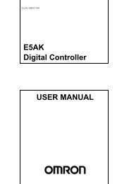
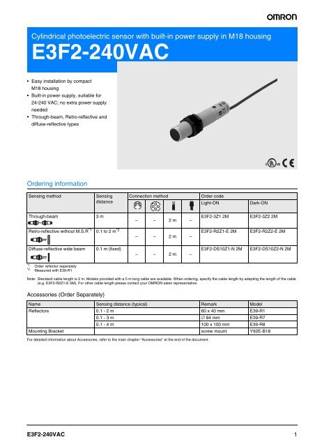
Cylindrical photoelectric sensor with built-in power supply in M18 housing<br />
<strong>E3F2</strong>-<strong>240VAC</strong><br />
• Easy installation by compact<br />
M18 housing<br />
Built-in power supply, suitable for<br />
24-240 VAC; no extra power supply<br />
needed<br />
Through-beam, Retro-reflective and<br />
diffuse-reflective types<br />
Ordering information<br />
Sensing method Sensing<br />
distance<br />
Through-beam 3 m<br />
Retro-reflective without M.S.R *1<br />
*1.<br />
Order reflector seperately<br />
*2.<br />
Measured with E39-R1<br />
Note: Standard cable length is 2 m. Models provided with a 5 m long cable are available. When ordering, specify the cable length by adapting the length of the cable<br />
(e.g. <strong>E3F2</strong>-R2Z1-E 5M). For other cable length please contact your <strong>OMRON</strong> sales representative.<br />
Accessories (Order Separately)<br />
For detailed information about Accessories, refer to the main chapter “Accessories” at the end of the document.<br />
<strong>E3F2</strong>-<strong>240VAC</strong><br />
0.1 to 2 m *2<br />
Diffuse-reflective wide beam 0.1 m (fixed)<br />
Connection method Order code<br />
Light-ON Dark-ON<br />
– – 2 m –<br />
– – 2 m –<br />
– – 2 m –<br />
<strong>E3F2</strong>-3Z1 2M <strong>E3F2</strong>-3Z2 2M<br />
<strong>E3F2</strong>-R2Z1-E 2M <strong>E3F2</strong>-R2Z2-E 2M<br />
<strong>E3F2</strong>-DS10Z1-N 2M <strong>E3F2</strong>-DS10Z2-N 2M<br />
Name Sensing distance (typical) Remark Model<br />
Reflectors 0.1 - 2 m 60 x 40 mm E39-R1<br />
0.1 - 3 m ∅ 84 mm E39-R7<br />
0.1 - 4 m 100 x 100 mm E39-R8<br />
Mounting Bracket screw mount Y92E-B18<br />
1
Specifications<br />
Ratings / Characteristics<br />
Item <strong>E3F2</strong>-3Z1<br />
<strong>E3F2</strong>-3Z2<br />
<strong>E3F2</strong>-R2Z1<br />
<strong>E3F2</strong>-R2Z2<br />
<strong>E3F2</strong>-DS10Z1<br />
<strong>E3F2</strong>-DS10Z2<br />
Type Through-beam Retro-reflective without M.S.R. Diffuse-reflective (wide-beam)<br />
Power supply voltage 24 to 240 VAC ±10 %, 50 / 60 Hz<br />
Current consumption 10 mA max. 5 mA max.<br />
Sensing distance *1<br />
3 m 0.1 to 2 m<br />
0.1 m<br />
(with E39-R1)<br />
(5 x 5 cm white mat paper)<br />
Detectable object Opaque object: 11 mm min. Opaque object: 56 mm min. Opaque objects<br />
Directional angle 3° to 20° –<br />
Differential travel – 20 % max.<br />
Response time 30 ms max.<br />
Control output AC solid state (SCR) 200 mA max.; residual voltage: 5 V max. at 200 mA<br />
Power reset time 100 ms<br />
Ambient illumination Incandescent lamp: 3000 lx max. Sunlight: 10000 lx max.<br />
Ambient temperature Operating: -25 to 55 °C / Storage: -30 to 70 °C (with no icing or condensation)<br />
Ambient humidity Operating: 35% to 85% / Storage: 35% to 95% (with no condensation)<br />
Insulation resistance 20 MΩ min. at 500 V DC between energized parts and case<br />
Dielectric strength 1500 VAC, 50 / 60 Hz for 1 min between energized parts and case<br />
Vibration resistance 10 to 55 Hz, 1.5 mm double amplitude for 2 hrs each direction (X, Y, Z)<br />
Shock resistance 500 m/sqr (approx. 50 g) for each direction (X, Y, Z)<br />
Degree of protection IEC 60529: IP66<br />
Light source (wave length) Infrared LED (880 nm)<br />
Indicators Light incident/power indicator for light source (red)<br />
Sensitivity adjustment Fixed<br />
Connection method 2 m, 5 m pre-wired cable (PVC dia. 4 mm (14 / 0.15)<br />
*1.<br />
For sensing distance in detail, please refer to ”Engineering Data”<br />
*2 )<br />
Operation mode Light-ON or Dark-ON (fixed)<br />
Circuit protection None<br />
Weight (approx.) 110 g (pre-wired 2 m cable)<br />
Housing materials Plastic (case: ABS; lens: PMMA)<br />
*2.<br />
For other cable materials (e.g. PUR) please contact your <strong>OMRON</strong> sales representative.<br />
2 Standard Photoelectric Sensors
Engineering Data (Typical)<br />
Operating Range (typical)<br />
Through-beam Models<br />
<strong>E3F2</strong>-3Z#<br />
Distance Y (mm)<br />
300<br />
200<br />
100<br />
0<br />
–100<br />
–200<br />
–300<br />
0<br />
Excess Gain Ratio vs. Distance (typical)<br />
Through-beam Models<br />
<strong>E3F2</strong>-3Z#<br />
Excess gain<br />
100<br />
10<br />
1<br />
0.1<br />
0<br />
<strong>E3F2</strong>-<strong>240VAC</strong><br />
typical sensing distance: 3.8 m<br />
1 2 3 4 5<br />
X<br />
Y<br />
Distance X (m)<br />
1 2 3 4 5 6<br />
Distance X (m)<br />
Retro-reflective Models<br />
<strong>E3F2</strong>-R2Z# (non polarizing)<br />
and reflectors<br />
Distance Y (mm)<br />
300<br />
200<br />
100<br />
0<br />
–100<br />
–200<br />
–300<br />
0<br />
1 2 3 4 5 6<br />
Retro-reflective Models<br />
<strong>E3F2</strong>-R2Z# (non polarizing)<br />
and reflectors<br />
Excess gain<br />
100<br />
10<br />
1<br />
reflector E39-R1<br />
reflector E39-R7<br />
reflector E39-R8<br />
typical sensing distances:<br />
E39-R1: 3.4 m<br />
E39-R7: 3.9 m<br />
E39-R8: 5.2 m<br />
Y<br />
X<br />
Reflector<br />
7<br />
8<br />
Distance X (m)<br />
0.1<br />
7 0 1 2 3 4 5 6<br />
7<br />
Distance X (m)<br />
Diffuse-reflective Models<br />
<strong>E3F2</strong>-DS10Z-# (wide-beam type)<br />
Distance Y (mm)<br />
30<br />
20<br />
10<br />
0<br />
–10<br />
–20<br />
–30<br />
0<br />
Y<br />
X<br />
Object<br />
20 40 60 80 100 120<br />
Diffuse-reflective Models<br />
<strong>E3F2</strong>-DS10Z-# (wide-beam type)<br />
Excess gain<br />
100<br />
10<br />
1<br />
0.1<br />
0<br />
Grey paper<br />
(18% reflectivity)<br />
50 100 150<br />
white paper<br />
(50 x 50 mm)<br />
140<br />
Distance X (mm)<br />
Sensing object:<br />
50 x 50 mm<br />
White paper<br />
(90% reflectivity)<br />
200<br />
Distance X (mm)<br />
3
Operation<br />
AC Output<br />
Model<br />
Output<br />
transistor status<br />
Timing chart<br />
<strong>E3F2</strong>-3LZ – – –<br />
<strong>E3F2</strong>-3Z1<br />
<strong>E3F2</strong>-R2Z1<br />
<strong>E3F2</strong>-DS10Z1-N<br />
<strong>E3F2</strong>-3Z2<br />
<strong>E3F2</strong>-R2Z2<br />
<strong>E3F2</strong>-DS10Z2-N<br />
ON when light is<br />
incident.<br />
(Light-ON)<br />
ON when light is<br />
interrupted. (Dark-<br />
ON)<br />
Incident<br />
Interrupted<br />
Output<br />
indicator<br />
(red)<br />
Output<br />
transistor<br />
Load<br />
(relay)<br />
Incident<br />
Interrupted<br />
Output<br />
indicator<br />
(red)<br />
Output<br />
transistor<br />
Load<br />
(relay)<br />
ON<br />
OFF<br />
ON<br />
OFF<br />
Operate<br />
Release<br />
ON<br />
OFF<br />
ON<br />
OFF<br />
Operate<br />
Release<br />
Connection<br />
method<br />
Output circuit<br />
Through-beam emitter<br />
4 Standard Photoelectric Sensors<br />
–<br />
–<br />
Light<br />
indicator<br />
Red<br />
Power<br />
indicator<br />
(red)<br />
Main<br />
circuit<br />
Main<br />
circuit<br />
Brown<br />
Blue<br />
Brown<br />
Black<br />
Blue<br />
24 to 240 VAC<br />
200 mA<br />
max. Load<br />
24 to 240 VAC
Dimensions Note: All units are in millimeters unless otherwise indicated<br />
Cable type<br />
Without potentiometer<br />
<strong>E3F2</strong>-3Z#<br />
<strong>E3F2</strong>-R2Z#<br />
<strong>E3F2</strong>-DS10Z#-N<br />
Accessories (Order Separately)<br />
Reflectors Installation<br />
E39-R1<br />
E39-R1S<br />
Material, reflective<br />
surface: acrylic<br />
Rear surface: ABS<br />
E39-R8<br />
E39-R7<br />
<strong>E3F2</strong>-<strong>240VAC</strong><br />
59.9<br />
Two, 3.5 dia.<br />
52<br />
1.6<br />
8<br />
40.3<br />
34<br />
9 100<br />
for M3<br />
7.4<br />
4.5<br />
7<br />
92<br />
90<br />
67.3<br />
62<br />
M18 x 1 6g<br />
84<br />
Light indicator<br />
8<br />
7.5<br />
92<br />
2.7<br />
100<br />
5 dia.<br />
16.8 dia.<br />
3.1<br />
Mounting Bracket<br />
Y92E-B18<br />
Note:<br />
Hexagon bolt: M5 x 32<br />
Material: plastic<br />
22<br />
24<br />
3.1<br />
optical zone<br />
5
Safety precautions<br />
This product is not designed or rated for directly or<br />
indirectly ensuring safety of persons. Do not use it for<br />
such a purpose.<br />
Do not use the product with voltage in excess of the<br />
rated voltage. Excess voltage may result in malfunction<br />
or fire.<br />
When cleaning the product, do not apply a high-pressure<br />
spray of water to one part of the product. Otherwise,<br />
parts may become damaged and the degree of<br />
protection may be degraded.<br />
High-temperature environments may result in burn<br />
injury.<br />
The following precautions must be observed to ensure safe<br />
operation of the Sensor.<br />
Operating Environment<br />
Do not use the Sensor in an environment where explosive or<br />
flammable gas is present.<br />
Load<br />
Do not use a load that exceeds the rated load. Do not connect the<br />
black wire to the brown wire without a load. Direct connection of<br />
these wires may damage the photoelectric sensor<br />
Sensor<br />
When you use the photoelectric sensor at temperatures exceeding<br />
45°C, the load current must be within the described values as shown<br />
in the figure below.<br />
Load current (mA)<br />
200<br />
130<br />
! Warning<br />
! Caution<br />
Precautions for Safe Use<br />
0<br />
Brown<br />
Black<br />
Blue<br />
Load<br />
24 to 240 VAC<br />
45<br />
Operating temperature (˚C)<br />
55<br />
Environements with Cleaners and Disinfectants<br />
(e.g., Food Processing Lines)<br />
Do not use the Sensor in environments subject to cleaners and<br />
disifectants. They may reduce the degree of protection.<br />
Modifications<br />
Do not attempt to disassemble, repair, or modify the Sensor.<br />
Outdoor Use<br />
Do not use the Sensor in locations subject to direct sunlight.<br />
Cleaning<br />
Do not use thinner, alcohol, or other organic solvents. Otherwise,<br />
the optical properties and degree of protection may be degraded.<br />
Surface Temperature<br />
Burn injury may occur. The Sensor surface temperature rises depending<br />
on application conditions, such as the surrounding temperature<br />
and the power supply voltage. Use caution when<br />
operating or washing the Sensor.<br />
Precautions for Correct Use<br />
Do not use the Sensor in any atmosphere or environment that<br />
exceeds the ratings.<br />
Do not install the Sensor in the following locations.<br />
(1)Locations subject to direct sunlight<br />
(2)Locations subject to condensation due to high humidity<br />
(3)Locations subject to corrosive gas<br />
(4)Locations where the Sensor may receive direct vibration or<br />
shock<br />
Connecting and Mounting<br />
(1)Laying Sensor wiring in the same conduit or duct as high-voltage<br />
wires or power lines may result in malfunction or damage<br />
due to induction. As a general rule, wire the Sensor in a separate<br />
conduit or use shielded cable.<br />
(2)Do not pull on the cable with excessive force.<br />
(3)Do not subject the photoelectric sensor to excessive shock<br />
when mounting, in keeping with IP66 standards.<br />
(4)Mount the Sensor using a bracket (sold separately).<br />
Do not exceed a torque of 2.0 Nm when tightening mounting<br />
nuts.<br />
Cleaning<br />
Never use thinner or other solvents. Otherwise, the Sensor surface<br />
may be dissolved.<br />
Water Resistance<br />
Do not use the Sensor in water, rainfall, or outdoors.<br />
6 Standard Photoelectric Sensors
Read and Understand This Catalog<br />
Please read and understand this catalog before purchasing the products. Please consult your <strong>OMRON</strong> representative if you have any questions or<br />
comments.<br />
Warranty and Limitations of Liability<br />
WARRANTY<br />
<strong>OMRON</strong>'s exclusive warranty is that the products are free from defects in materials and workmanship for a period of one year (or other period if specified)<br />
from date of sale by <strong>OMRON</strong>.<br />
<strong>OMRON</strong> MAKES NO WARRANTY OR REPRESENTATION, EXPRESS OR IMPLIED, REGARDING NON-INFRINGEMENT, MERCHANTABILITY, OR<br />
FITNESS FOR PARTICULAR PURPOSE OF THE PRODUCTS. ANY BUYER OR USER ACKNOWLEDGES THAT THE BUYER OR USER ALONE HAS<br />
DETERMINED THAT THE PRODUCTS WILL SUITABLY MEET THE REQUIREMENTS OF THEIR INTENDED USE. <strong>OMRON</strong> DISCLAIMS ALL OTHER<br />
WARRANTIES, EXPRESS OR IMPLIED.<br />
LIMITATIONS OF LIABILITY<br />
<strong>OMRON</strong> SHALL NOT BE RESPONSIBLE FOR SPECIAL, INDIRECT, OR CONSEQUENTIAL DAMAGES, LOSS OF PROFITS OR COMMERCIAL LOSS<br />
IN ANY WAY CONNECTED WITH THE PRODUCTS, WHETHER SUCH CLAIM IS BASED ON CONTRACT, WARRANTY, NEGLIGENCE, OR STRICT<br />
LIABILITY.<br />
In no event shall the responsibility of <strong>OMRON</strong> for any act exceed the individual price of the product on which liability is asserted.<br />
IN NO EVENT SHALL <strong>OMRON</strong> BE RESPONSIBLE FOR WARRANTY, REPAIR, OR OTHER CLAIMS REGARDING THE PRODUCTS UNLESS<br />
<strong>OMRON</strong>'S ANALYSIS CONFIRMS THAT THE PRODUCTS WERE PROPERLY HANDLED, STORED, INSTALLED, AND MAINTAINED AND NOT<br />
SUBJECT TO CONTAMINATION, ABUSE, MISUSE, OR INAPPROPRIATE MODIFICATION OR REPAIR.<br />
Application Considerations<br />
SUITABILITY FOR USE<br />
<strong>OMRON</strong> shall not be responsible for conformity with any standards, codes, or regulations that apply to the combination of products in the customer's<br />
application or use of the products.<br />
At the customer's request, <strong>OMRON</strong> will provide applicable third party certification documents identifying ratings and limitations of use that apply to the<br />
products. This information by itself is not sufficient for a complete determination of the suitability of the products in combination with the end product,<br />
machine, system, or other application or use.<br />
The following are some examples of applications for which particular attention must be given. This is not intended to be an exhaustive list of all possible<br />
uses of the products, nor is it intended to imply that the uses listed may be suitable for the products:<br />
• Outdoor use, uses involving potential chemical contamination or electrical interference, or conditions or uses not described in this catalog.<br />
• Nuclear energy control systems, combustion systems, railroad systems, aviation systems, medical equipment, amusement machines, vehicles,<br />
safety equipment, and installations subject to separate industry or government regulations.<br />
• Systems, machines, and equipment that could present a risk to life or property.<br />
Please know and observe all prohibitions of use applicable to the products.<br />
NEVER USE THE PRODUCTS FOR AN APPLICATION INVOLVING SERIOUS RISK TO LIFE OR PROPERTY WITHOUT ENSURING THAT THE<br />
SYSTEM AS A WHOLE HAS BEEN DESIGNED TO ADDRESS THE RISKS, AND THAT THE <strong>OMRON</strong> PRODUCTS ARE PROPERLY RATED AND<br />
INSTALLED FOR THE INTENDED USE WITHIN THE OVERALL EQUIPMENT OR SYSTEM.<br />
PROGRAMMABLE PRODUCTS<br />
<strong>OMRON</strong> shall not be responsible for the user's programming of a programmable product, or any consequence thereof.<br />
Disclaimers<br />
CHANGE IN SPECIFICATIONS<br />
Product specifications and accessories may be changed at any time based on improvements and other reasons.<br />
It is our practice to change model numbers when published ratings or features are changed, or when significant construction changes are made.<br />
However, some specifications of the products may be changed without any notice. When in doubt, special model numbers may be assigned to fix or<br />
establish key specifications for your application on your request. Please consult with your <strong>OMRON</strong> representative at any time to confirm actual<br />
specifications of purchased products.<br />
DIMENSIONS AND WEIGHTS<br />
Dimensions and weights are nominal and are not to be used for manufacturing purposes, even when tolerances are shown.<br />
PERFORMANCE DATA<br />
Performance data given in this catalog is provided as a guide for the user in determining suitability and does not constitute a warranty. It may represent the<br />
result of <strong>OMRON</strong>’s test conditions, and the users must correlate it to actual application requirements. Actual performance is subject to the <strong>OMRON</strong><br />
Warranty and Limitations of Liability.<br />
ERRORS AND OMISSIONS<br />
The information in this document has been carefully checked and is believed to be accurate; however, no responsibility is assumed for clerical,<br />
typographical, or proofreading errors, or omissions.<br />
<strong>OMRON</strong> Corporation<br />
Industrial Automation Company<br />
http://www.ia.omron.com/<br />
2009.6<br />
In the interest of product improvement, specifications are subject to change without notice.<br />
(c)Copyright <strong>OMRON</strong> Corporation 2009 All Right Reserved.