A16 2 - OMRON
A16 2 - OMRON
A16 2 - OMRON

You also want an ePaper? Increase the reach of your titles
YUMPU automatically turns print PDFs into web optimized ePapers that Google loves.
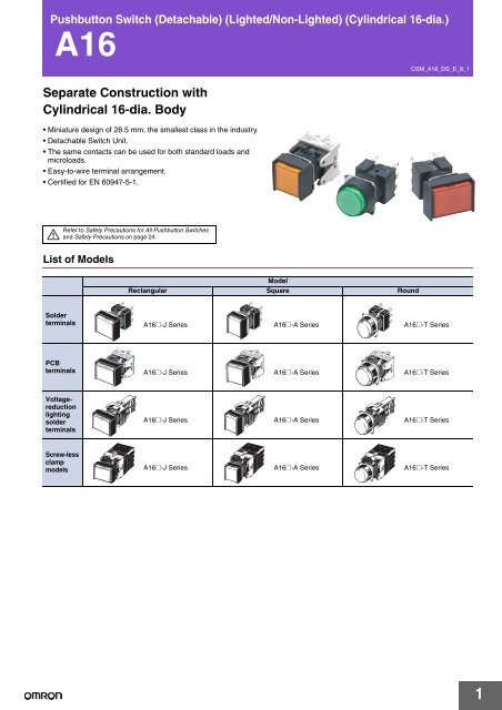
Pushbutton Switch (Detachable) (Lighted/Non-Lighted) (Cylindrical 16-dia.)<br />
<strong>A16</strong><br />
Separate Construction with<br />
Cylindrical 16-dia. Body<br />
• Miniature design of 28.5 mm, the smallest class in the industry.<br />
Detachable Switch Unit.<br />
The same contacts can be used for both standard loads and<br />
microloads.<br />
Easy-to-wire terminal arrangement.<br />
Certified for EN 60947-5-1.<br />
Refer to Safety Precautions for All Pushbutton Switches<br />
and Safety Precautions on page 24.<br />
List of Models<br />
Model<br />
Rectangular Square Round<br />
CSM_<strong>A16</strong>_DS_E_8_1<br />
Solder<br />
terminals <strong>A16</strong>@-J Series <strong>A16</strong>@-A Series <strong>A16</strong>@-T Series<br />
PCB<br />
terminals <strong>A16</strong>@-J Series <strong>A16</strong>@-A Series <strong>A16</strong>@-T Series<br />
Voltagereduction<br />
lighting<br />
solder<br />
terminals<br />
<strong>A16</strong>@-J Series <strong>A16</strong>@-A Series <strong>A16</strong>@-T Series<br />
Screw-less<br />
clamp<br />
models <strong>A16</strong>@-J Series <strong>A16</strong>@-A Series <strong>A16</strong>@-T Series<br />
1
Model Number Structure<br />
<strong>A16</strong><br />
Model Number Legend ..... The model numbers used to order sets of Units are illustrated below. One set comprises the Pushbutton, Lamp<br />
(lighted models only), Case, and Switch. For information on combinations, refer to Ordering Information on<br />
pages 3 to 7.<br />
(1) Degree of Protection<br />
Symbol Protection<br />
No symbol IP40<br />
5<br />
Oil-resistant<br />
IP65<br />
(2) Lighted/Non-lighted<br />
Symbol Type<br />
No symbol Non-lighted<br />
L Lighted<br />
(3) Shape of Pushbutton<br />
Symbol Shape<br />
J<br />
Rectangular<br />
2-way guard<br />
A Square 2-way guard<br />
T Round<br />
Projecting<br />
model<br />
(1) (2) (3) (4) (5) (6) (7)<br />
<strong>A16</strong> 5 L - J R M - 24D - 2<br />
(4) Color of Pushbutton<br />
Symbol Color<br />
R Red<br />
Y Yellow<br />
PY Pure yellow<br />
G Green<br />
W White<br />
A Blue<br />
PW Pure white<br />
Black (non-lighted<br />
B<br />
models only)<br />
Color illuminated models are also<br />
available (see page 8).<br />
Order the parts separately.<br />
(6) Light Source<br />
(7) Contact Configuration<br />
Symbol Type Terminal<br />
1<br />
2<br />
SPDT<br />
DPDT<br />
Solder Terminal<br />
1P<br />
2P<br />
SPDT<br />
DPDT<br />
PCB Terminal<br />
2S DPDT Screw-less Clamp<br />
Only DPDT contacts are available with Screw-<br />
Less Clamp.<br />
Consult your <strong>OMRON</strong> representative<br />
concerning pricing and delivery timing for PCB<br />
terminals and screw-less clamp connectors.<br />
(5) Switch Operation<br />
Symbol Operation<br />
M Momentary<br />
A Alternate<br />
Momentary-operation:<br />
Self-resetting<br />
Alternate-operation:<br />
Self-holding<br />
Symbol<br />
No symbol<br />
5<br />
12<br />
24<br />
5D<br />
12D<br />
Type<br />
Incandescent<br />
lamp<br />
LED<br />
Operating Rated<br />
voltage voltage<br />
Non-lighted<br />
5 VAC/VDC 6 VAC/VDC<br />
12 VAC/VDC 14 VAC/VDC<br />
24 VAC/VDC 28 VAC/VDC<br />
5 ± 5% VDC 5 VDC<br />
12 ± 5%<br />
12 VAC/VDC<br />
VAC/VDC<br />
Colored Illumination<br />
24 ± 5%<br />
24D<br />
24 VAC/VDC<br />
VAC/VDC<br />
Unlit Lit<br />
Voltage Reduction Unit (24-V Built-in LED)<br />
White Color<br />
The built-in<br />
LED is colored.<br />
Symbol Type<br />
Operating<br />
voltage<br />
Rated<br />
voltage<br />
T1<br />
T2<br />
LED<br />
100 to 110<br />
VAC/VDC<br />
200 to 220<br />
VAC/VDC<br />
100/110<br />
VAC/VDC<br />
200/220<br />
VAC/VDC<br />
Solder terminals are available only with 100-V models.<br />
The Voltage Reduction Unit is not available for models with<br />
PCB terminals.<br />
“T2” is available only for the Screw-less Clamp type.<br />
2
Ordering Information<br />
Ordering as a Set .................The model numbers used to order sets of Units are given in the following tables. One set comprises the<br />
Pushbutton, Lamp (lighted models only), Case, and Switch.<br />
Solder Terminal Models<br />
Rectangular Models<br />
IP40<br />
Output Lighting<br />
Item<br />
Operating<br />
voltage<br />
*1. Enter the desired color symbol for the Pushbutton in the @.<br />
*2. Black (“B”) Pushbuttons are only available for non-lighted models.<br />
Momentary operation<br />
(Self-resetting)<br />
Alternate operation<br />
(Self-holding)<br />
<strong>A16</strong><br />
Pushbutton color<br />
symbol *1<br />
LED without<br />
Voltage<br />
Reduction<br />
Unit<br />
5 VDC<br />
12 VAC/VDC<br />
24 VAC/VDC<br />
<strong>A16</strong>L-J@M-5D-1<br />
<strong>A16</strong>L-J@M-12D-1<br />
<strong>A16</strong>L-J@M-24D-1<br />
<strong>A16</strong>L-J@A-5D-1<br />
<strong>A16</strong>L-J@A-12D-1<br />
<strong>A16</strong>L-J@A-24D-1<br />
R: red, Y: yellow<br />
PY: pure yellow<br />
G: green, A: blue<br />
W: white<br />
PW: pure white<br />
SPDT<br />
Incandescent<br />
lamp<br />
5 VAC/VDC<br />
12 VAC/VDC<br />
24 VAC/VDC<br />
<strong>A16</strong>L-J@M-5-1<br />
<strong>A16</strong>L-J@M-12-1<br />
<strong>A16</strong>L-J@M-24-1<br />
<strong>A16</strong>L-J@A-5-1<br />
<strong>A16</strong>L-J@A-12-1<br />
<strong>A16</strong>L-J@A-24-1<br />
R: red, Y: yellow<br />
PY: pure yellow<br />
G: green, W: white<br />
A: blue<br />
Non-lighted <strong>A16</strong>-J@M-1 <strong>A16</strong>-J@A-1<br />
B: black *2<br />
LED without<br />
Voltage<br />
Reduction<br />
Unit<br />
5 VDC<br />
12 VAC/VDC<br />
24 VAC/VDC<br />
<strong>A16</strong>L-J@M-5D-2<br />
<strong>A16</strong>L-J@M-12D-2<br />
<strong>A16</strong>L-J@M-24D-2<br />
<strong>A16</strong>L-J@A-5D-2<br />
<strong>A16</strong>L-J@A-12D-2<br />
<strong>A16</strong>L-J@A-24D-2<br />
R: red, Y: yellow<br />
PY: pure yellow<br />
G: green, A: blue<br />
W: white<br />
PW: pure white<br />
DPDT<br />
Incandescent<br />
lamp<br />
5 VAC/VDC<br />
12 VAC/VDC<br />
24 VAC/VDC<br />
<strong>A16</strong>L-J@M-5-2<br />
<strong>A16</strong>L-J@M-12-2<br />
<strong>A16</strong>L-J@M-24-2<br />
<strong>A16</strong>L-J@A-5-2<br />
<strong>A16</strong>L-J@A-12-2<br />
<strong>A16</strong>L-J@A-24-2<br />
R: red, Y: yellow<br />
PY: pure yellow<br />
G: green, W: white<br />
A: blue<br />
Non-lighted <strong>A16</strong>-J@M-2 <strong>A16</strong>-J@A-2<br />
B: black *2<br />
*1. Enter the desired color symbol for the Pushbutton in the @.<br />
*2. Black (“B”) Pushbuttons are only available for non-lighted models.<br />
Oil-resistant IP65<br />
Output Lighting<br />
SPDT<br />
DPDT<br />
Item<br />
Operating<br />
voltage<br />
<strong>A16</strong>@-J<br />
Momentary operation<br />
(Self-resetting)<br />
Alternate operation<br />
(Self-holding)<br />
Pushbutton color<br />
symbol *1<br />
LED without<br />
Voltage<br />
Reduction<br />
Unit<br />
5 VDC<br />
12 VAC/VDC<br />
24 VAC/VDC<br />
<strong>A16</strong>5L-J@M-5D-1<br />
<strong>A16</strong>5L-J@M-12D-1<br />
<strong>A16</strong>5L-J@M-24D-1<br />
<strong>A16</strong>5L-J@A-5D-1<br />
<strong>A16</strong>5L-J@A-12D-1<br />
<strong>A16</strong>5L-J@A-24D-1<br />
R: red, Y: yellow<br />
PY: pure yellow<br />
G: green, A: blue<br />
W: white<br />
PW: pure white<br />
Incandescent<br />
lamp<br />
5 VAC/VDC<br />
12 VAC/VDC<br />
24 VAC/VDC<br />
<strong>A16</strong>5L-J@M-5-1<br />
<strong>A16</strong>5L-J@M-12-1<br />
<strong>A16</strong>5L-J@M-24-1<br />
<strong>A16</strong>5L-J@A-5-1<br />
<strong>A16</strong>5L-J@A-12-1<br />
<strong>A16</strong>5L-J@A-24-1<br />
R: red, Y: yellow<br />
PY: pure yellow<br />
G: green, W: white<br />
A: blue<br />
Non-lighted <strong>A16</strong>5-J@M-1 <strong>A16</strong>5-J@A-1<br />
B: black *2<br />
LED without<br />
Voltage<br />
Reduction<br />
Unit<br />
5 VDC<br />
12 VAC/VDC<br />
24 VAC/VDC<br />
<strong>A16</strong>5L-J@M-5D-2<br />
<strong>A16</strong>5L-J@M-12D-2<br />
<strong>A16</strong>5L-J@M-24D-2<br />
<strong>A16</strong>5L-J@A-5D-2<br />
<strong>A16</strong>5L-J@A-12D-2<br />
<strong>A16</strong>5L-J@A-24D-2<br />
R: red, Y: yellow<br />
PY: pure yellow<br />
G: green, A: blue<br />
W: white<br />
PW: pure white<br />
Incandescent<br />
lamp<br />
5 VAC/VDC<br />
12 VAC/VDC<br />
24 VAC/VDC<br />
<strong>A16</strong>5L-J@M-5-2<br />
<strong>A16</strong>5L-J@M-12-2<br />
<strong>A16</strong>5L-J@M-24-2<br />
<strong>A16</strong>5L-J@A-5-2<br />
<strong>A16</strong>5L-J@A-12-2<br />
<strong>A16</strong>5L-J@A-24-2<br />
R: red, Y: yellow<br />
PY: pure yellow<br />
G: green, W: white<br />
A: blue<br />
Non-lighted <strong>A16</strong>5-J@M-2 <strong>A16</strong>5-J@A-2<br />
B: black *2<br />
Individual models: Refer to pages 9 to 13.<br />
(The Pushbutton, Lamp, Case, and Switch can be ordered<br />
separately.)<br />
■ Ratings: Refer to page 16. ■ Characteristics: Refer to page 16.<br />
■ Accessories: Refer to page 15.<br />
3
Ordering Information<br />
Ordering as a Set ................. The model numbers used to order sets of Units are given in the following tables. One set comprises the<br />
Pushbutton, Lamp (lighted models only), Case, and Switch.<br />
Solder Terminal Models<br />
Square Models<br />
IP40<br />
Output Lighting<br />
Item<br />
Operating<br />
voltage<br />
*1. Enter the desired color symbol for the Pushbutton in the @.<br />
*2. Black (“B”) Pushbuttons are only available for non-lighted models.<br />
Momentary operation<br />
(Self-resetting)<br />
Alternate operation<br />
(Self-holding)<br />
<strong>A16</strong><br />
Pushbutton color<br />
symbol *1<br />
LED without<br />
Voltage<br />
Reduction<br />
Unit<br />
5 VDC<br />
12 VAC/VDC<br />
24 VAC/VDC<br />
<strong>A16</strong>L-A@M-5D-1<br />
<strong>A16</strong>L-A@M-12D-1<br />
<strong>A16</strong>L-A@M-24D-1<br />
<strong>A16</strong>L-A@A-5D-1<br />
<strong>A16</strong>L-A@A-12D-1<br />
<strong>A16</strong>L-A@A-24D-1<br />
R: red, Y: yellow<br />
PY: pure yellow<br />
G: green, A: blue<br />
W: white<br />
PW: pure white<br />
SPDT<br />
Incandescent<br />
lamp<br />
5 VAC/VDC<br />
12 VAC/VDC<br />
24 VAC/VDC<br />
<strong>A16</strong>L-A@M-5-1<br />
<strong>A16</strong>L-A@M-12-1<br />
<strong>A16</strong>L-A@M-24-1<br />
<strong>A16</strong>L-A@A-5-1<br />
<strong>A16</strong>L-A@A-12-1<br />
<strong>A16</strong>L-A@A-24-1<br />
R: red, Y: yellow<br />
PY: pure yellow<br />
G: green, W: white<br />
A: blue<br />
Non-lighted <strong>A16</strong>-A@M-1 <strong>A16</strong>-A@A-1<br />
B: black *2<br />
LED without<br />
Voltage<br />
Reduction<br />
Unit<br />
5 VDC<br />
12 VAC/VDC<br />
24 VAC/VDC<br />
<strong>A16</strong>L-A@M-5D-2<br />
<strong>A16</strong>L-A@M-12D-2<br />
<strong>A16</strong>L-A@M-24D-2<br />
<strong>A16</strong>L-A@A-5D-2<br />
<strong>A16</strong>L-A@A-12D-2<br />
<strong>A16</strong>L-A@A-24D-2<br />
R: red, Y: yellow<br />
PY: pure yellow<br />
G: green, A: blue<br />
W: white<br />
PW: pure white<br />
DPDT<br />
Incandescent<br />
lamp<br />
5 VAC/VDC<br />
12 VAC/VDC<br />
24 VAC/VDC<br />
<strong>A16</strong>L-A@M-5-2<br />
<strong>A16</strong>L-A@M-12-2<br />
<strong>A16</strong>L-A@M-24-2<br />
<strong>A16</strong>L-A@A-5-2<br />
<strong>A16</strong>L-A@A-12-2<br />
<strong>A16</strong>L-A@A-24-2<br />
R: red, Y: yellow<br />
PY: pure yellow<br />
G: green, W: white<br />
A: blue<br />
Non-lighted <strong>A16</strong>-A@M-2 <strong>A16</strong>-A@A-2<br />
B: black *2<br />
*1. Enter the desired color symbol for the Pushbutton in the @.<br />
*2. Black (“B”) Pushbuttons are only available for non-lighted models.<br />
Oil-resistant IP65<br />
Output Lighting<br />
SPDT<br />
DPDT<br />
<strong>A16</strong>@-A<br />
Item<br />
Operating<br />
voltage<br />
Momentary operation<br />
(Self-resetting)<br />
Alternate operation<br />
(Self-holding)<br />
Pushbutton color<br />
symbol *1<br />
LED without<br />
Voltage<br />
Reduction<br />
Unit<br />
5 VDC<br />
12 VAC/VDC<br />
24 VAC/VDC<br />
<strong>A16</strong>5L-A@M-5D-1<br />
<strong>A16</strong>5L-A@M-12D-1<br />
<strong>A16</strong>5L-A@M-24D-1<br />
<strong>A16</strong>5L-A@A-5D-1<br />
<strong>A16</strong>5L-A@A-12D-1<br />
<strong>A16</strong>5L-A@A-24D-1<br />
R: red, Y: yellow<br />
PY: pure yellow<br />
G: green, A: blue<br />
W: white<br />
PW: pure white<br />
Incandescent<br />
lamp<br />
5 VAC/VDC<br />
12 VAC/VDC<br />
24 VAC/VDC<br />
<strong>A16</strong>5L-A@M-5-1<br />
<strong>A16</strong>5L-A@M-12-1<br />
<strong>A16</strong>5L-A@M-24-1<br />
<strong>A16</strong>5L-A@A-5-1<br />
<strong>A16</strong>5L-A@A-12-1<br />
<strong>A16</strong>5L-A@A-24-1<br />
R: red, Y: yellow<br />
PY: pure yellow<br />
G: green, W: white<br />
A: blue<br />
Non-lighted <strong>A16</strong>5-A@M-1 <strong>A16</strong>5-A@A-1<br />
B: black *2<br />
LED without<br />
Voltage<br />
Reduction<br />
Unit<br />
5 VDC<br />
12 VAC/VDC<br />
24 VAC/VDC<br />
<strong>A16</strong>5L-A@M-5D-2<br />
<strong>A16</strong>5L-A@M-12D-2<br />
<strong>A16</strong>5L-A@M-24D-2<br />
<strong>A16</strong>5L-A@A-5D-2<br />
<strong>A16</strong>5L-A@A-12D-2<br />
<strong>A16</strong>5L-A@A-24D-2<br />
R: red, Y: yellow<br />
PY: pure yellow<br />
G: green, A: blue<br />
W: white<br />
PW: pure white<br />
Incandescent<br />
lamp<br />
5 VAC/VDC<br />
12 VAC/VDC<br />
24 VAC/VDC<br />
<strong>A16</strong>5L-A@M-5-2<br />
<strong>A16</strong>5L-A@M-12-2<br />
<strong>A16</strong>5L-A@M-24-2<br />
<strong>A16</strong>5L-A@A-5-2<br />
<strong>A16</strong>5L-A@A-12-2<br />
<strong>A16</strong>5L-A@A-24-2<br />
R: red, Y: yellow<br />
PY: pure yellow<br />
G: green, W: white<br />
A: blue<br />
Non-lighted <strong>A16</strong>5-A@M-2 <strong>A16</strong>5-A@A-2<br />
B: black *2<br />
Individual models: Refer to pages 9 to 13.<br />
(The Pushbutton, Lamp, Case, and Switch can be ordered<br />
separately.)<br />
■ Ratings: Refer to page 16. ■ Characteristics: Refer to page 16.<br />
■ Accessories: Refer to page 15.<br />
4
Ordering Information<br />
Ordering as a Set .................The model numbers used to order sets of Units are given in the following tables. One set comprises the<br />
Pushbutton, Lamp (lighted models only), Case, and Switch.<br />
Solder Terminals<br />
Round Models<br />
IP40<br />
Output Lighting<br />
<strong>A16</strong>@-T<br />
Item<br />
Operating<br />
voltage<br />
*1. Enter the desired color symbol for the Pushbutton in the @.<br />
*2. Black (“B”) Pushbuttons are only available for non-lighted models.<br />
Momentary operation<br />
(Self-resetting)<br />
Alternate operation<br />
(Self-holding)<br />
<strong>A16</strong><br />
Pushbutton color<br />
symbol *1<br />
LED without<br />
Voltage<br />
Reduction<br />
Unit<br />
5 VDC<br />
12 VAC/VDC<br />
24 VAC/VDC<br />
<strong>A16</strong>L-T@M-5D-1<br />
<strong>A16</strong>L-T@M-12D-1<br />
<strong>A16</strong>L-T@M-24D-1<br />
<strong>A16</strong>L-T@A-5D-1<br />
<strong>A16</strong>L-T@A-12D-1<br />
<strong>A16</strong>L-T@A-24D-1<br />
R: red, Y: yellow<br />
PY: pure yellow<br />
G: green, A: blue<br />
W: white<br />
PW: pure white<br />
SPDT<br />
Incandescent<br />
lamp<br />
5 VAC/VDC<br />
12 VAC/VDC<br />
24 VAC/VDC<br />
<strong>A16</strong>L-T@M-5-1<br />
<strong>A16</strong>L-T@M-12-1<br />
<strong>A16</strong>L-T@M-24-1<br />
<strong>A16</strong>L-T@A-5-1<br />
<strong>A16</strong>L-T@A-12-1<br />
<strong>A16</strong>L-T@A-24-1<br />
R: red, Y: yellow<br />
PY: pure yellow<br />
G: green, W: white<br />
A: blue<br />
Non-lighted <strong>A16</strong>-T@M-1 <strong>A16</strong>-T@A-1<br />
B: black *2<br />
LED without<br />
Voltage<br />
Reduction<br />
Unit<br />
5 VDC<br />
12 VAC/VDC<br />
24 VAC/VDC<br />
<strong>A16</strong>L-T@M-5D-2<br />
<strong>A16</strong>L-T@M-12D-2<br />
<strong>A16</strong>L-T@M-24D-2<br />
<strong>A16</strong>L-T@A-5D-2<br />
<strong>A16</strong>L-T@A-12D-2<br />
<strong>A16</strong>L-T@A-24D-2<br />
R: red, Y: yellow<br />
PY: pure yellow<br />
G: green, A: blue<br />
W: white<br />
PW: pure white<br />
DPDT<br />
Incandescent<br />
lamp<br />
5 VAC/VDC<br />
12 VAC/VDC<br />
24 VAC/VDC<br />
<strong>A16</strong>L-T@M-5-2<br />
<strong>A16</strong>L-T@M-12-2<br />
<strong>A16</strong>L-T@M-24-2<br />
<strong>A16</strong>L-T@A-5-2<br />
<strong>A16</strong>L-T@A-12-2<br />
<strong>A16</strong>L-T@A-24-2<br />
R: red, Y: yellow<br />
PY: pure yellow<br />
G: green, W: white<br />
A: blue<br />
Non-lighted <strong>A16</strong>-T@M-2 <strong>A16</strong>-T@A-2<br />
B: black *2<br />
*1. Enter the desired color symbol for the Pushbutton in the @.<br />
*2. Black (“B”) Pushbuttons are only available for non-lighted models.<br />
Oil-resistant IP65<br />
Output Lighting<br />
SPDT<br />
DPDT<br />
Item<br />
Operating<br />
voltage<br />
Momentary operation<br />
(Self-resetting)<br />
Alternate operation<br />
(Self-holding)<br />
Pushbutton color<br />
symbol *1<br />
LED without<br />
Voltage<br />
Reduction<br />
Unit<br />
5 VDC<br />
12 VAC/VDC<br />
24 VAC/VDC<br />
<strong>A16</strong>5L-T@M-5D-1<br />
<strong>A16</strong>5L-T@M-12D-1<br />
<strong>A16</strong>5L-T@M-24D-1<br />
<strong>A16</strong>5L-T@A-5D-1<br />
<strong>A16</strong>5L-T@A-12D-1<br />
<strong>A16</strong>5L-T@A-24D-1<br />
R: red, Y: yellow<br />
PY: pure yellow<br />
G: green, A: blue<br />
W: white<br />
PW: pure white<br />
Incandescent<br />
lamp<br />
5 VAC/VDC<br />
12 VAC/VDC<br />
24 VAC/VDC<br />
<strong>A16</strong>5L-T@M-5-1<br />
<strong>A16</strong>5L-T@M-12-1<br />
<strong>A16</strong>5L-T@M-24-1<br />
<strong>A16</strong>5L-T@A-5-1<br />
<strong>A16</strong>5L-T@A-12-1<br />
<strong>A16</strong>5L-T@A-24-1<br />
R: red, Y: yellow<br />
PY: pure yellow<br />
G: green, W: white<br />
A: blue<br />
Non-lighted <strong>A16</strong>5-T@M-1 <strong>A16</strong>5-T@A-1<br />
B: black *2<br />
LED without<br />
Voltage<br />
Reduction<br />
Unit<br />
5 VDC<br />
12 VAC/VDC<br />
24 VAC/VDC<br />
<strong>A16</strong>5L-T@M-5D-2<br />
<strong>A16</strong>5L-T@M-12D-2<br />
<strong>A16</strong>5L-T@M-24D-2<br />
<strong>A16</strong>5L-T@A-5D-2<br />
<strong>A16</strong>5L-T@A-12D-2<br />
<strong>A16</strong>5L-T@A-24D-2<br />
R: red, Y: yellow<br />
PY: pure yellow<br />
G: green, A: blue<br />
W: white<br />
PW: pure white<br />
Incandescent<br />
lamp<br />
5 VAC/VDC<br />
12 VAC/VDC<br />
24 VAC/VDC<br />
<strong>A16</strong>5L-T@M-5-2<br />
<strong>A16</strong>5L-T@M-12-2<br />
<strong>A16</strong>5L-T@M-24-2<br />
<strong>A16</strong>5L-T@A-5-2<br />
<strong>A16</strong>5L-T@A-12-2<br />
<strong>A16</strong>5L-T@A-24-2<br />
R: red, Y: yellow<br />
PY: pure yellow<br />
G: green, W: white<br />
A: blue<br />
Non-lighted <strong>A16</strong>5-T@M-2 <strong>A16</strong>5-T@A-2<br />
B: black *2<br />
Individual models: Refer to pages 9 to 13.<br />
(The Pushbutton, Lamp, Case, and Switch can be ordered<br />
separately.)<br />
■ Ratings: Refer to page 16. ■ Characteristics: Refer to page 16.<br />
■ Accessories: Refer to page 15.<br />
5
Ordering Information<br />
Ordering as a Set ................. The model numbers used to order sets of Units are given in the following tables. One set comprises the<br />
Pushbutton, Lamp (lighted models only), Case, and Switch.<br />
Models with Reduced-voltage Lighting and Solder Terminals<br />
IP40<br />
<strong>A16</strong><br />
Item Momentary operation<br />
Alternate operation Pushbutton color<br />
Output Lighting Operating voltage (Self-resetting)<br />
(Self-holding)<br />
symbol *<br />
SPDT<br />
LED (with built-in<br />
100/110 VAC/VDC <strong>A16</strong>L-∆@M-T1-1 <strong>A16</strong>L-∆@A-T1-1<br />
R: red, Y: yellow<br />
PY: pure yellow<br />
reduced-voltage<br />
G: green, W: white<br />
DPDT lighting function) 100/110 VAC/VDC <strong>A16</strong>L-∆@M-T1-2 <strong>A16</strong>L-∆@A-T1-2<br />
A: blue<br />
PW: pure white<br />
* Enter the desired shape for the Pushbutton in ∆: J (rectangular), A (square), or T (round). Enter the desired color symbol for the Pushbutton in the @.<br />
Oil-resistant IP65<br />
Item Momentary operation<br />
Output Lighting Operating voltage (Self-resetting)<br />
* Enter the desired shape for the Pushbutton in ∆: J (rectangular), A (square), or T (round). Enter the desired color symbol for the Pushbutton in the @.<br />
Screw-less Clamp Models<br />
Alternate operation<br />
(Self-holding)<br />
SPDT<br />
LED (with built-in<br />
reduced-voltage<br />
100/110 VAC/VDC <strong>A16</strong>5L-∆@M-T1-1 <strong>A16</strong>5L-∆@A-T1-1<br />
DPDT lighting function) 100/110 VAC/VDC <strong>A16</strong>5L-∆@M-T1-2 <strong>A16</strong>5L-∆@A-T1-2<br />
IP40<br />
Item Momentary operation<br />
Output Lighting Operating voltage (Self-resetting)<br />
DPDT<br />
LED<br />
LED (with built-in<br />
reduced-voltage<br />
lighting function)<br />
Alternate operation<br />
(Self-holding)<br />
5 VDC <strong>A16</strong>L-∆@M-5D-2S <strong>A16</strong>L-∆@A-5D-2S<br />
12 VAC/VDC <strong>A16</strong>L-∆@M-12D-2S <strong>A16</strong>L-∆@A-12D-2S<br />
24 VAC/VDC <strong>A16</strong>L-∆@M-24D-2S <strong>A16</strong>L-∆@A-24D-2S<br />
100/110 VAC/VDC <strong>A16</strong>L-∆@M-T1-2S <strong>A16</strong>L-∆@A-T1-2S<br />
200/220 VAC/VDC <strong>A16</strong>L-∆@M-T2-2S <strong>A16</strong>L-∆@A-T2-2S<br />
Non-lighted <strong>A16</strong>-∆@M-2S <strong>A16</strong>-∆@A-2S<br />
*1. Enter the desired shape for the Pushbutton in ∆: J (rectangular), A (square), or T (round). Enter the desired color symbol for the Pushbutton in the @.<br />
*2. Black (“B”) Pushbuttons are only available for non-lighted models.<br />
Oil-resistant IP65<br />
Item Momentary operation<br />
Output Lighting Operating voltage (Self-resetting)<br />
DPDT<br />
LED<br />
LED (with built-in<br />
reduced-voltage<br />
lighting function)<br />
<strong>A16</strong>@-T1<br />
Note: Models with voltage ratings of 200 to 220 VAC/DC (T2 models) are listed with models with screw-less clamp<br />
<strong>A16</strong>@-2S<br />
Alternate operation<br />
(Self-holding)<br />
5 VDC <strong>A16</strong>5L-∆@M-5D-2S <strong>A16</strong>5L-∆@A-5D-2S<br />
12 VAC/VDC <strong>A16</strong>5L-∆@M-12D-2S <strong>A16</strong>5L-∆@A-12D-2S<br />
24 VAC/VDC <strong>A16</strong>5L-∆@M-24D-2S <strong>A16</strong>5L-∆@A-24D-2S<br />
100/110 VAC/VDC <strong>A16</strong>5L-∆@M-T1-2S <strong>A16</strong>5L-∆@A-T1-2S<br />
200/220 VAC/VDC <strong>A16</strong>5L-∆@M-T2-2S <strong>A16</strong>5L-∆@A-T2-2S<br />
Non-lighted <strong>A16</strong>5-∆@M-2S <strong>A16</strong>5-∆@A-2S<br />
*1. Enter the desired shape for the Pushbutton in ∆: J (rectangular), A (square), or T (round). Enter the desired color symbol for the Pushbutton in the @.<br />
*2. Black (“B”) Pushbuttons are only available for non-lighted models.<br />
Pushbutton color<br />
symbol *<br />
R: red, Y: yellow<br />
PY: pure yellow<br />
G: green, W: white<br />
A: blue<br />
PW: pure white<br />
Pushbutton color<br />
symbol *1<br />
R: red, Y: yellow<br />
PY: pure yellow<br />
G: green, W: white<br />
A: blue<br />
PW: pure white<br />
B: black *2<br />
Pushbutton color<br />
symbol *1<br />
R: red, Y: yellow<br />
PY: pure yellow<br />
G: green, W: white<br />
A: blue<br />
PW: pure white<br />
B: black *2<br />
6
Ordering Information<br />
Ordering as a Set .................The model numbers used to order sets of Units are given in the following tables. One set comprises the<br />
Pushbutton, Lamp (lighted models only), Case, and Switch.<br />
Models with PCB Terminals<br />
IP40<br />
Item Momentary operation<br />
Output Lighting Operating voltage (Self-resetting)<br />
SPDT<br />
DPDT<br />
LED<br />
5 VDC <strong>A16</strong>L-∆@M-5D-1P<br />
12 VAC/VDC <strong>A16</strong>L-∆@M-12D-1P<br />
24 VAC/VDC <strong>A16</strong>L-∆@M-24D-1P<br />
Non-lighted <strong>A16</strong>-∆@M-1P<br />
LED<br />
5 VDC <strong>A16</strong>L-∆@M-5D-2P<br />
12 VAC/VDC <strong>A16</strong>L-∆@M-12D-2P<br />
24 VAC/VDC <strong>A16</strong>L-∆@M-24D-2P<br />
Non-lighted <strong>A16</strong>-∆@M-2P<br />
Pushbutton color<br />
symbol *1<br />
R: red<br />
Y: yellow<br />
PY: pure yellow<br />
G: green<br />
A: blue<br />
W: white<br />
B: black *2<br />
Note: Contact your <strong>OMRON</strong> representative about Selector Switches and Key Selector Switches.<br />
*1. Enter the desired shape for the Pushbutton in ∆: J (rectangular), A (square), or T (round). Enter the desired color symbol for the Pushbutton in the @.<br />
*2. Black (“B”) Pushbuttons are only available for non-lighted models.<br />
IP65<br />
Item Momentary operation<br />
Output Lighting Operating voltage (Self-resetting)<br />
SPDT<br />
DPDT<br />
LED<br />
5 VDC <strong>A16</strong>5L-∆@M-5D-1P<br />
12 VAC/VDC <strong>A16</strong>5L-∆@M-12D-1P<br />
24 VAC/VDC <strong>A16</strong>5L-∆@M-24D-1P<br />
Non-lighted <strong>A16</strong>5-∆@M-1P<br />
LED<br />
<strong>A16</strong>@-P<br />
5 VDC <strong>A16</strong>5L-∆@M-5D-2P<br />
12 VAC/VDC <strong>A16</strong>5L-∆@M-12D-2P<br />
24 VAC/VDC <strong>A16</strong>5L-∆@M-24D-2P<br />
Non-lighted <strong>A16</strong>5-∆@M-2P<br />
Pushbutton color<br />
symbol *1<br />
R: red<br />
Y: yellow<br />
PY: pure yellow<br />
G: green<br />
A: blue<br />
W: white<br />
B: black *2<br />
Note: Contact your <strong>OMRON</strong> representative about Selector Switches and Key Selector Switches.<br />
*1. Enter the desired shape for the Pushbutton in ∆: J (rectangular), A (square), or T (round). Enter the desired color symbol for the Pushbutton in the @.<br />
*2. Black (“B”) Pushbuttons are only available for non-lighted models.<br />
<strong>A16</strong><br />
7
Ordering Information<br />
Illumination Only and Colored Illumination for Models with LEDs<br />
With illumination only, the color of the lighted surface is the same when the LED is lit and when it is not lit.<br />
Example: Red Illumination<br />
With colored illumination, the color of the lighted surface is white when the LED is not lit and the LED emits another color when it is lit.<br />
Example: Red Illumination<br />
Ordering: For colored illumination, order the Operation Unit, Case, Lamp, and Socket Unit separately.<br />
Color emitted<br />
when lit<br />
Red<br />
Not lit<br />
Operation Unit Case Lamp (LED) Socket Unit<br />
IP40<br />
<strong>A16</strong>L-@W<br />
IP65<br />
<strong>A16</strong>5L-@W<br />
Insert one of the following<br />
symbols into<br />
Cap (red)<br />
Red Legend plate<br />
Lit<br />
Red<br />
Not lit<br />
IP40<br />
Momentary: <strong>A16</strong>-C@M<br />
Alternate: <strong>A16</strong>-C@A<br />
Dispersion plate (milky white)<br />
Reflective plunger<br />
LED lamp (red) Lamp<br />
Cap (translucent)<br />
White Legend plate<br />
Lit<br />
Red<br />
Dispersion plate (milky white)<br />
Reflection plunger<br />
LED lamp (red) Lamp<br />
<strong>A16</strong>-@DSR<br />
Yellow<br />
IP65<br />
Momentary: <strong>A16</strong>5-C@M<br />
Alternate: <strong>A16</strong>5-C@A<br />
<strong>A16</strong>-@DSY<br />
Green<br />
Blue<br />
the box (@).<br />
J: Rectangular<br />
A: Square<br />
T: Round<br />
Insert one of the following symbols<br />
into the box (@).<br />
J: Rectangular (2-way guard)<br />
A: Square (2-way guard)<br />
T: Round (projected)<br />
<strong>A16</strong>-@DSG<br />
<strong>A16</strong>-@DA<br />
Operation Unit<br />
Operation Unit<br />
Specify one of the following<br />
symbols in the<br />
box (@).<br />
5: 5 VDC<br />
12: 12 VAC/VDC<br />
24: 24 VAC/VDC<br />
<strong>A16</strong><br />
Refer to page 14. Any<br />
Switch can be mounted.<br />
8
Ordering Information<br />
<strong>A16</strong><br />
Ordering Individually .........Pushbuttons, Lamps, Cases, and Switches (Sockets) can be ordered separately. Combinations that are not<br />
available as sets can be created using individual Units. Also, store the parts as spares for maintenance and<br />
repairs.<br />
Pushbutton<br />
Rectangular Models<br />
Note: Use IP40 Operation Units with IP40<br />
Socket Units and use IP65 Operation<br />
Units with IP65 Socket Units. There is no<br />
Legend Plate built into the Operation Unit.<br />
Lighted Models<br />
Lamp<br />
LED Incandescent lamp<br />
Square Models Round Models<br />
Case<br />
Note: Operation Unit Sets that combine an Operation Unit and a Case are also<br />
available. (Refer to page 10.)<br />
Socket<br />
Solder terminals<br />
(no transformer)<br />
Non-lighted Models<br />
Ordering set combinations: Refer to pages 3 to 7. ■ Specifications: Refer to page 16.<br />
Lighted/non-lighted Note: Socket Unit Sets that combine a Lamp and a Socket Unit are<br />
also available. (Refer to page 11.)<br />
■ Accessories, Replacement, and Tools: Refer to page 15.<br />
9
Ordering Information<br />
Units ............................... Select an Operation Unit Set (Operation Unit and Case) and a Socket Unit Set (Lamp and Socket Unit).<br />
Unit Sets....................... Sets that combine an Operation Unit and a Case.<br />
Operation Unit<br />
Insert one of the following symbols into the box (@).<br />
Operation Unit<br />
Socket Unit Set with Voltage-reduction Lighting Socket Unit Set with Screw-less Clamp Connectors<br />
Appearance Classification Model<br />
IP40<br />
Oil-resistant IP65<br />
Momentary<br />
operation<br />
Alternate operation<br />
Momentary<br />
operation<br />
Alternate operation<br />
Symbol Color Remarks<br />
R Red<br />
Y<br />
PY<br />
A<br />
Yellow<br />
Pure yellow<br />
Blue<br />
LED indicator, incandescent<br />
lamp, or non-lighted<br />
W White*<br />
GY Green LED only<br />
G Green Incandescent lamp or non-lighted<br />
B Black Non-lighted only<br />
* Use this pushbutton color if the illumination color of the LED is white or pure white.<br />
Rectangular, square, round<br />
Lighted Models Lighted/Non-lighted Model<br />
Voltage-reduction<br />
lighting<br />
Lamp<br />
Note: An LED rated 24 VAC/VDC is built-in.<br />
Lighted/Non-lighted<br />
Lamp<br />
Note: Non-lighted models do not include a Lamp.<br />
Rectangular (2-way guard) <strong>A16</strong>-J@M<br />
Square (2-way guard) <strong>A16</strong>-A@M<br />
Round (projected) <strong>A16</strong>-T@M<br />
Rectangular (2-way guard) <strong>A16</strong>-J@A<br />
Square (2-way guard) <strong>A16</strong>-A@A<br />
Round (projected) <strong>A16</strong>-T@A<br />
Rectangular (2-way guard) <strong>A16</strong>5-J@M<br />
Square (2-way guard) <strong>A16</strong>5-A@M<br />
Round (projected) <strong>A16</strong>5-T@M<br />
Rectangular (2-way guard) <strong>A16</strong>5-J@A<br />
Square (2-way guard) <strong>A16</strong>5-A@A<br />
Round (projected) <strong>A16</strong>5-T@A<br />
<strong>A16</strong><br />
10
Ordering Information<br />
Unit Sets ....................... Sets that combine a Socket Unit and a Lamp.<br />
Socket Unit Sets with Incandescent Lamps<br />
Appearance Classification Model<br />
Socket Unit Sets with LED Lamps<br />
Socket Unit Set with Voltage-reduction Lighting (Soldered Terminals)<br />
Note: An LED rated 24 VAC/VDC is built-in.<br />
Screw-less Clamp Socket Unit Sets<br />
Note: The 100-V models and 200-V models an LED rated 24 VAC/VDC is built-in.<br />
Insert symbols in Δ and @.<br />
Δ @<br />
Standard loads and<br />
microloads<br />
Solder terminals<br />
Note: If the Operation Unit is pure yellow (PY), use white (W) for the Socket Unit Set.<br />
SPDT <strong>A16</strong>L-@-1<br />
DPDT <strong>A16</strong>L-@-2<br />
Appearance Classification Model<br />
Standard loads and<br />
microloads<br />
Solder terminals<br />
PCB terminals<br />
SPDT <strong>A16</strong>L-Δ-@-1<br />
DPDT <strong>A16</strong>L-Δ-@-2<br />
SPDT <strong>A16</strong>L-Δ-@-1P<br />
DPDT <strong>A16</strong>L-Δ-@-2P<br />
Appearance Classification Operating voltage Model<br />
Standard loads and microloads<br />
SPDT 100/110 VAC/VDC <strong>A16</strong>L- Δ-T1-1<br />
DPDT 100/110 VAC/VDC <strong>A16</strong>L-Δ-T1-2<br />
Appearance Classification Model<br />
Non-lighted <strong>A16</strong>-2S<br />
No voltage-reduction lighting <strong>A16</strong>L-Δ-@-2S<br />
Standard loads and<br />
microloads<br />
DPDT<br />
Lighted<br />
Voltage-reduction<br />
lighting<br />
100/110 VAC/VDC <strong>A16</strong>L-Δ-T1-2S<br />
Note. 200/220 VAC/VDC <strong>A16</strong>L-Δ-T2-2S<br />
Symbol Color Symbol Type<br />
Operating<br />
voltage<br />
R Red 5<br />
5 VAC/VDC<br />
Y Yellow 12 Incandescent 12 VAC/VDC<br />
G Green 24 24 VAC/VDC<br />
W White 5D<br />
5 VDC<br />
A Blue 12D LED 12 VAC/VDC<br />
24D 24 VAC/VDC<br />
<strong>A16</strong><br />
11
Ordering Information<br />
<strong>A16</strong><br />
Ordering Individually......... Pushbuttons, Lamps, Cases, and Switches (Sockets) can be ordered separately. Combinations that are not<br />
available as sets can be created using individual Units. Also, store the parts as spares for maintenance and<br />
repairs.<br />
Pushbuttons<br />
LED<br />
Degree of protection IP40 Oil-resistant IP65<br />
Rectangular Square Round Rectangular Square Round<br />
Color<br />
Red <strong>A16</strong>L-JR <strong>A16</strong>L-AR <strong>A16</strong>L-TR <strong>A16</strong>5L-JR <strong>A16</strong>5L-AR <strong>A16</strong>5L-TR<br />
Yellow <strong>A16</strong>L-JY <strong>A16</strong>L-AY <strong>A16</strong>L-TY <strong>A16</strong>5L-JY <strong>A16</strong>5L-AY <strong>A16</strong>5L-TY<br />
Pure yellow <strong>A16</strong>L-JPY <strong>A16</strong>L-APY <strong>A16</strong>L-TPY <strong>A16</strong>5L-JPY <strong>A16</strong>5L-APY <strong>A16</strong>5L-TPY<br />
Green <strong>A16</strong>L-JGY <strong>A16</strong>L-AGY <strong>A16</strong>L-TGY <strong>A16</strong>5L-JGY <strong>A16</strong>5L-AGY <strong>A16</strong>5L-TGY<br />
White* <strong>A16</strong>L-JW <strong>A16</strong>L-AW <strong>A16</strong>L-TW <strong>A16</strong>5L-JW <strong>A16</strong>5L-AW <strong>A16</strong>5L-TW<br />
Blue <strong>A16</strong>L-JA <strong>A16</strong>L-AA <strong>A16</strong>L-TA <strong>A16</strong>5L-JA <strong>A16</strong>5L-AA <strong>A16</strong>5L-TA<br />
* Use this pushbutton color if the illumination color of the LED is white or pure white.<br />
Incandescent Lamps (With the exception of green, the Units are the same as for LEDs.)<br />
Degree of protection IP40 Oil-resistant IP65<br />
Rectangular Square Round Rectangular Square Round<br />
Color<br />
Red <strong>A16</strong>L-JR <strong>A16</strong>L-AR <strong>A16</strong>L-TR <strong>A16</strong>5L-JR <strong>A16</strong>5L-AR <strong>A16</strong>5L-TR<br />
Yellow <strong>A16</strong>L-JY <strong>A16</strong>L-AY <strong>A16</strong>L-TY <strong>A16</strong>5L-JY <strong>A16</strong>5L-AY <strong>A16</strong>5L-TY<br />
Pure yellow <strong>A16</strong>L-JPY <strong>A16</strong>L-APY <strong>A16</strong>L-TPY <strong>A16</strong>5L-JPY <strong>A16</strong>5L-APY <strong>A16</strong>5L-TPY<br />
Green <strong>A16</strong>L-JG <strong>A16</strong>L-AG <strong>A16</strong>L-TG <strong>A16</strong>5L-JG <strong>A16</strong>5L-AG <strong>A16</strong>5L-TG<br />
White <strong>A16</strong>L-JW <strong>A16</strong>L-AW <strong>A16</strong>L-TW <strong>A16</strong>5L-JW <strong>A16</strong>5L-AW <strong>A16</strong>5L-TW<br />
Blue <strong>A16</strong>L-JA <strong>A16</strong>L-AA <strong>A16</strong>L-TA <strong>A16</strong>5L-JA <strong>A16</strong>5L-AA <strong>A16</strong>5L-TA<br />
Non-lighted (Same as Units for incandescent lamps.)<br />
Degree of protection IP40 Oil-resistant IP65<br />
Rectangular Square Round Rectangular Square Round<br />
Color<br />
Red <strong>A16</strong>L-JR <strong>A16</strong>L-AR <strong>A16</strong>L-TR <strong>A16</strong>5L-JR <strong>A16</strong>5L-AR <strong>A16</strong>5L-TR<br />
Yellow <strong>A16</strong>L-JY <strong>A16</strong>L-AY <strong>A16</strong>L-TY <strong>A16</strong>5L-JY <strong>A16</strong>5L-AY <strong>A16</strong>5L-TY<br />
Pure yellow <strong>A16</strong>L-JPY <strong>A16</strong>L-APY <strong>A16</strong>L-TPY <strong>A16</strong>5L-JPY <strong>A16</strong>5L-APY <strong>A16</strong>5L-TPY<br />
Green <strong>A16</strong>L-JG <strong>A16</strong>L-AG <strong>A16</strong>L-TG <strong>A16</strong>5L-JG <strong>A16</strong>5L-AG <strong>A16</strong>5L-TG<br />
White <strong>A16</strong>L-JW <strong>A16</strong>L-AW <strong>A16</strong>L-TW <strong>A16</strong>5L-JW <strong>A16</strong>5L-AW <strong>A16</strong>5L-TW<br />
Blue <strong>A16</strong>L-JA <strong>A16</strong>L-AA <strong>A16</strong>L-TA <strong>A16</strong>5L-JA <strong>A16</strong>5L-AA <strong>A16</strong>5L-TA<br />
Black <strong>A16</strong>L-JB <strong>A16</strong>L-AB <strong>A16</strong>L-TB <strong>A16</strong>5L-JB <strong>A16</strong>5L-AB <strong>A16</strong>5L-TB<br />
Ordering set combinations: Refer to pages 3 to 7. ■ Specifications: Refer to page 16.<br />
■ Accessories, Replacement, and Tools: Refer to page 15.<br />
12
Ordering Information<br />
<strong>A16</strong><br />
Ordering Individually .........Pushbuttons, Lamps, Cases, and Switches (Sockets) can be ordered separately. Combinations that are not<br />
available as sets can be created using individual Units. Also, store the parts as spares for maintenance and<br />
repairs.<br />
Lamps<br />
LED<br />
Light color<br />
Note: 1. If an LED lamp with normal brightness is needed, select a Lamp used in the A3C.<br />
2. For voltage-reduction lighting use the <strong>A16</strong>-24D@. Only 24 VAC/VDC LED lamps can be used.<br />
* Use the white LED together with white or pure yellow Pushbuttons.<br />
Incandescent Lamp<br />
Cases<br />
Operating voltage<br />
High brightness<br />
5 VDC 12 VAC/VDC 24 VAC/VDC<br />
Red <strong>A16</strong>-5DSR <strong>A16</strong>-12DSR <strong>A16</strong>-24DSR<br />
Yellow <strong>A16</strong>-5DSY <strong>A16</strong>-12DSY <strong>A16</strong>-24DSY<br />
Green <strong>A16</strong>-5DSG <strong>A16</strong>-12DSG <strong>A16</strong>-24DSG<br />
White * <strong>A16</strong>-5DSW <strong>A16</strong>-12DSW <strong>A16</strong>-24DSW<br />
Blue <strong>A16</strong>-5DA <strong>A16</strong>-12DA <strong>A16</strong>-24DA<br />
Pure white <strong>A16</strong>-5DPW <strong>A16</strong>-12DPW <strong>A16</strong>-24DPW<br />
Appearance Operating voltage Model<br />
5 VAC/VDC <strong>A16</strong>-5<br />
12 VAC/VDC <strong>A16</strong>-12<br />
24 VAC/VDC <strong>A16</strong>-24<br />
Appearance Classification Model<br />
Rectangular (2-way guard) <strong>A16</strong>-CJM<br />
Momentary operation Square (2-way guard) <strong>A16</strong>-CAM<br />
IP40<br />
Round (projected)<br />
Rectangular (2-way guard)<br />
<strong>A16</strong>-CTM<br />
<strong>A16</strong>-CJA<br />
Alternate operation Square (2-way guard) <strong>A16</strong>-CAA<br />
Round (projected) <strong>A16</strong>-CTA<br />
Rectangular (2-way guard) <strong>A16</strong>5-CJM<br />
Momentary operation Square (2-way guard) <strong>A16</strong>5-CAM<br />
Oil-resistant IP65<br />
Round (projected)<br />
Rectangular (2-way guard)<br />
<strong>A16</strong>5-CTM<br />
<strong>A16</strong>5-CJA<br />
Alternate operation Square (2-way guard) <strong>A16</strong>5-CAA<br />
Round (projected) <strong>A16</strong>5-CTA<br />
Ordering set combinations: Refer to pages 3 to 7. ■ Specifications: Refer to page 16.<br />
■ Accessories, Replacement, and Tools: Refer to page 15.<br />
13
Ordering Information<br />
Switches<br />
Appearance Classification Model<br />
Solder terminal<br />
PCB terminal<br />
Screw-less Clamp<br />
Switches with Reduced-voltage Lighting<br />
Lighted/non-lighted (common use)<br />
Note: For voltage-reduction use the <strong>A16</strong>-24D@. Only 24 VAC/VDC LED lamps can be used.<br />
Standard load/microload<br />
(common use)<br />
SPDT <strong>A16</strong>-1<br />
DPDT <strong>A16</strong>-2<br />
SPDT <strong>A16</strong>-1P<br />
DPDT <strong>A16</strong>-2P<br />
DPDT <strong>A16</strong>-2S<br />
Appearance Classification Model<br />
Solder terminal<br />
Screw-less Clamp<br />
100 V<br />
100 V<br />
Standard load/microload<br />
(common use)<br />
SPDT <strong>A16</strong>-T1-1<br />
DPDT <strong>A16</strong>-T1-2<br />
DPDT<br />
<strong>A16</strong>-T1-2S<br />
200 V <strong>A16</strong>-T2-2S<br />
<strong>A16</strong><br />
14
Ordering Information<br />
Accessories, Replacements, and Tools<br />
Accessories<br />
Replacements<br />
Tools<br />
Name Appearance Classification Model Remarks<br />
Switch Guards<br />
Dust Covers<br />
Panel Plugs<br />
For rectangular models <strong>A16</strong>ZJ-5050<br />
For square and round<br />
models<br />
<strong>A16</strong>ZA-5050<br />
For rectangular models <strong>A16</strong>ZJ-5060<br />
For square models <strong>A16</strong>ZA-5060<br />
For round models <strong>A16</strong>ZT-5060<br />
Cannot be used with the Dust Cover.<br />
Cannot be used with the Switch Guard.<br />
Can be operated with the Dust Cover attached.<br />
<strong>A16</strong><br />
For rectangular models <strong>A16</strong>ZJ-3003 Used for covering the panel cutouts for future panel<br />
For square models <strong>A16</strong>ZA-3003<br />
expansion.<br />
Protective structure: IP40<br />
For round models <strong>A16</strong>ZT-3003 Color: Black<br />
Name Appearance Classification Model Remarks<br />
Rectangular<br />
Oil-resistant<br />
IP65<br />
Milky <strong>A16</strong>ZJ-5204 A single Legend Plate (Milky<br />
white) is included with a standard<br />
Legend Plates<br />
Square<br />
Oil-resistant<br />
IP65<br />
Milky <strong>A16</strong>ZA-5204<br />
model.<br />
The milky Legend Plate can be<br />
Round<br />
Oil-resistant<br />
IP65<br />
Milky <strong>A16</strong>ZT-5204<br />
used with the IP40 and oil-resistant<br />
IP65.<br />
White <strong>A16</strong>Z@-5001W<br />
Color Caps (for<br />
IP40)<br />
Rectangular<br />
LED lamp/incandescent<br />
lamp/nonlighted<br />
Red<br />
Yellow<br />
Pure yellow<br />
Blue<br />
<strong>A16</strong>Z@-5001R<br />
<strong>A16</strong>Z@-5001Y<br />
<strong>A16</strong>Z@-5001PY<br />
<strong>A16</strong>Z@-5001A<br />
Insert one of the following letters<br />
into the box (@).<br />
J: Rectangular<br />
A: Square<br />
T: Round<br />
Color Caps (for<br />
oil-resistant IP65)<br />
Square<br />
Round<br />
LED lamp<br />
Incandescent lamp/non-lighted<br />
Non-lighted<br />
LED lamp/incandescent<br />
lamp/nonlighted<br />
LED lamp<br />
Incandescent lamp/non-lighted<br />
Green<br />
Green<br />
Black<br />
White<br />
Red<br />
Yellow<br />
Pure yellow<br />
Blue<br />
Green<br />
Green<br />
<strong>A16</strong>Z@-5001GY<br />
<strong>A16</strong>Z@-5001G<br />
<strong>A16</strong>Z@-5011B<br />
<strong>A16</strong>Z@-5101W<br />
<strong>A16</strong>Z@-5101R<br />
<strong>A16</strong>Z@-5101Y<br />
<strong>A16</strong>Z@-5101PY<br />
<strong>A16</strong>Z@-5101A<br />
<strong>A16</strong>Z@-5101GY<br />
<strong>A16</strong>Z@-5101G<br />
The Color Cap is usually supplied.<br />
Replace the Cap if the color is to<br />
be changed.<br />
When using an LED indicator, be<br />
sure to use a Color Cap that<br />
matches the luminescent color of<br />
the LED.<br />
The materials used for the IP40<br />
and oil-resistant IP65 are different<br />
so be sure to use a Color Cap that<br />
matches the specifications of the<br />
Switch.<br />
Non-lighted Black <strong>A16</strong>Z@-5111B<br />
Name Appearance Model<br />
Operation Unit<br />
Extractor<br />
Pushbutton<br />
Switch<br />
Knob-type<br />
Selector<br />
Switch<br />
Applicable types<br />
Key-type<br />
Selector<br />
Switch<br />
Emergency<br />
Stop<br />
Switch<br />
Indicator<br />
A3PJ-5080 ● — — — ●<br />
Screw Fitting <strong>A16</strong>Z-3004 ● ● ● ● ●<br />
Socket Unit Lamp<br />
Extractor<br />
<strong>A16</strong>Z-5080 ● ● ● ● ●<br />
Remarks<br />
Convenient for extracting<br />
Pushbutton<br />
Switches<br />
Convenient for<br />
ganged installation.<br />
Convenient for extracting<br />
the Switch<br />
and Lamps.<br />
15
Specifications<br />
Approved Standard Ratings<br />
UL, cUL (File No. E41515) TÜV (EN60947-5-1) (Low Voltage Directive) CCC (GB14048.5)<br />
5 A at 125 VAC, 3 A at 250 VAC (general use)<br />
3 A at 30 VDC (resistive)<br />
Note: Certification has been obtained for the Socket Unit.<br />
For detailed information on individual products that<br />
have received certification, consult your supplier.<br />
Ratings<br />
Contacts<br />
Rated voltage Resistive load<br />
125 VAC 5 A<br />
250 VAC 3 A<br />
30 VDC 3 A<br />
Minimum applicable load: 1 mA at 5 VDC<br />
Rated values are obtained from tests conducted under the following<br />
conditions.<br />
1. Load: Resistive load<br />
2. Mounting conditions: No vibration and no shock<br />
3. Temperature: 20 ±2°C<br />
4. Operating frequency: 20 operations/min<br />
Contact Form<br />
Name Contact<br />
DPDT COM<br />
Characteristics<br />
Socket Unit<br />
Item Type Pushbutton Switch<br />
Allowable<br />
operating<br />
frequency<br />
Mechanical<br />
*1. Set and reset constitute one operation.<br />
*2. With LED and incandescent lamp not mounted.<br />
*3. Degree of protection from the front of the panel.<br />
NC<br />
NO<br />
3 A at 250 VAC<br />
3 A at 30 VDC<br />
Momentary operation: 120 operations/minute max.<br />
Alternate operation: 60 operations/minute max. *1<br />
Electrical 20 operations/minute max. *1<br />
Insulation resistance 100 MΩ min. (at 500 VDC)<br />
Dielectric<br />
strength<br />
Between terminals<br />
of same polarity<br />
Between terminals<br />
of different polarity<br />
Between each terminal<br />
and ground<br />
Between lamp terminals<br />
Vibration<br />
resistance Malfunction<br />
Shock<br />
resistance<br />
Durability Mechanical<br />
Destruction 500 m/s 2<br />
1,000 VAC, 50/60 Hz for 1 minute<br />
2,000 VAC, 50/60 Hz for 1 minute<br />
2,000 VAC, 50/60 Hz for 1 minute<br />
1,000 VAC, 50/60 Hz for 1 minute *2<br />
10 to 55 Hz, 1.5-mm double amplitude<br />
(malfunction within 1 ms)<br />
Malfunction 150 m/s 2 max. (malfunction within 1 ms)<br />
Momentary operation: 2,000,000 operations min.<br />
Alternate operation: 200,000 operations min. *1<br />
Electrical 100,000 operations min. *1<br />
Electric shock protection class Class II<br />
PTI (tracking characteristic) 175<br />
Degree of contamination 3 (IEC947-5-1)<br />
Weight<br />
Approx. 10 g (in the case of a lighted<br />
DPDT switch with solder terminals)<br />
Degree of protection IP40: <strong>A16</strong>, Oil-resistant IP65: <strong>A16</strong>5 *3<br />
Ambient operating temperature –10°C to 55°C (with no icing or condensation)<br />
Ambient operating humidity 35% to 85%RH<br />
Ambient storage temperature –25°C to 65°C (with no icing or condensation)<br />
Super-bright LED<br />
Rated<br />
voltage<br />
5 VDC<br />
Rated<br />
current<br />
Incandescent Lamp<br />
Voltage-reduction Unit (LED Lamp)<br />
Screw-less Clamp<br />
Operating<br />
voltage<br />
Operating Characteristics<br />
5 A at 125 VAC<br />
3 A at 250 VAC<br />
3 A at 30 VDC<br />
<strong>A16</strong><br />
Internal limiting resistor<br />
5 VDC ±5%<br />
Red, yellow, white: 300 Ω<br />
Green, blue, pure white: 160 Ω<br />
12 VAC/VDC<br />
8 mA<br />
12 VAC/VDC ±5%<br />
Red, yellow, white: 1 kΩ<br />
Green, blue, pure white: 910 Ω<br />
24 VAC/VDC 24 VAC/VDC ±5% 2.4 kΩ<br />
Rated voltage Rated current Operating voltage<br />
6 VAC/VDC 60 mA 5 VAC/VDC<br />
14 VAC/VDC 40 mA 12 VAC/VDC<br />
28 VAC/VDC 24 mA 24 VAC/VDC<br />
Rated voltage Operating voltage Applicable lamp<br />
110 VAC/VDC<br />
220 VAC/VDC<br />
100/110 VAC/VDC<br />
(90 to 121 V)<br />
200/220 VAC/VDC<br />
(180 to 242 V)<br />
<strong>A16</strong>-24DS@<br />
LED Lamp<br />
Item Screw-Less Clamp<br />
Recommended wire size 0.5 mm 2 twisted wire or 0.8 mm-dia. solid wire<br />
Usable wires<br />
and tensile<br />
strength<br />
Twisted<br />
wire<br />
Solid<br />
wire<br />
Tensile<br />
strength<br />
0.3 mm 2 0.5 mm 2 0.75 mm 2 1.25 mm 2<br />
0.5 mm<br />
dia.<br />
0.8 mm<br />
dia.<br />
1.0 mm<br />
dia.<br />
Type Pushbutton Switch<br />
Characteristics IP40 Oil-resistant IP65<br />
Operating force (OF) max. 4.41 N 4.91 N<br />
Releasing force (RF) min. 0.29 N<br />
Total travel (TT) Approx. 3 mm<br />
Pretravel (PT) max. 2.5 mm<br />
Lock travel alternate (LTA) min. *<br />
* Alternate operation models only.<br />
0.5 mm<br />
—<br />
10 N 20 N 30 N 40 N<br />
Length of exposed wire 10 ±1mm<br />
Compliant standards JIS C 2811 Terminal Blocks for Industrial Use<br />
16
Nomenclature<br />
Model Structure<br />
Pushbutton<br />
Cap<br />
Legend plate<br />
Dispersion plate<br />
Reflective plunger<br />
●Flange Shape<br />
Rectangular (<strong>A16</strong>@-J)<br />
Square (<strong>A16</strong>@-A)<br />
Round (<strong>A16</strong>@-T)<br />
●Terminal Type<br />
Solder terminals<br />
(tab terminals #110)<br />
PCB terminals<br />
Screw-less Clamp<br />
●Color of Pushbutton<br />
· LED/incandescent models<br />
Red, Green, Yellow, White, Blue<br />
· Neon models<br />
Red, Green, White<br />
· Non-lighted models<br />
Red, Green, Yellow, White, Blue, Black<br />
●Degree of Protection<br />
IP40/Oil-resistant IP65<br />
Lamp<br />
Switch<br />
●Switch Ratings<br />
5 A at 125 VAC<br />
3 A at 250 VAC<br />
3 A at 30 VDC<br />
Minimum applicable load: 1 mA at 5 VDC<br />
<strong>A16</strong><br />
17
<strong>A16</strong><br />
Dimensions • The Dimension shows 2-switch outputs. • The lamp terminal is also provided with non-lighted models. (Unit: mm)<br />
Rectangular<br />
<strong>A16</strong>@-J<br />
Solder terminals (tab terminals #110)<br />
18 15.1<br />
Square<br />
<strong>A16</strong>@-A<br />
Solder terminals (tab terminals #110)<br />
18 15.1<br />
Round<br />
<strong>A16</strong>@-T<br />
Solder terminals (tab terminals #110)<br />
18<br />
21<br />
24<br />
15.1<br />
18<br />
18 dia. 15.1 dia.<br />
9.5<br />
6<br />
9.5<br />
6<br />
28.5<br />
21.1<br />
10.8<br />
4<br />
M16×1<br />
Lock ring<br />
Mounting nut<br />
12.2<br />
Packing (t0.5)<br />
(for oil-resistant IP65 only)<br />
28.5<br />
21.1<br />
10.8<br />
4<br />
M16×1<br />
Lock ring<br />
Mounting nut<br />
9.5<br />
6<br />
12.2<br />
Packing (t0.5)<br />
(for oil-resistant IP65 only)<br />
28.5<br />
21.1<br />
10.8<br />
4<br />
M16×1<br />
Lock ring<br />
Mounting nut<br />
Lamp terminal<br />
18<br />
Lamp terminal<br />
2.8<br />
4.85 12.4 15.8<br />
Lamp terminals<br />
18<br />
Lamp terminals<br />
12.2<br />
18 Packing (t0.5)<br />
(for oil-resistant IP65 only)<br />
2.8<br />
4.85 12.4 15.8<br />
Lamp terminals<br />
18<br />
Lamp terminals<br />
2.8<br />
4.85 12.4 15.8<br />
• See page 21 for panel cutouts<br />
+0.2<br />
16 0 dia.<br />
+0.2<br />
16 0 dia.<br />
19 min.<br />
24 min.<br />
• See page 21 for panel cutouts<br />
19 min.<br />
• See page 21 for panel cutouts<br />
+0.2<br />
16 0 dia.<br />
19 min.<br />
19 min.<br />
19 min.<br />
18
<strong>A16</strong><br />
Dimensions • The Dimension shows 2-switch outputs. • The lamp terminal is also provided with non-lighted models. • A rectangular model is listed as an example. (Unit: mm)<br />
Rectangular<br />
<strong>A16</strong>@-J@-@P<br />
PCB terminals<br />
18 15.1<br />
Rectangular<br />
<strong>A16</strong>@-J@-T1<br />
Voltage-reduction lighting, solder terminals<br />
(tab terminals #110)<br />
Rectangular<br />
<strong>A16</strong>@-J@-2S, T1-2S, T2-2S<br />
Screw-less Clamp<br />
Lamps<br />
LED<br />
<strong>A16</strong>-5D@/-12D@/-24D@<br />
6 dia.<br />
12 max. 4<br />
*<br />
15.1<br />
18<br />
18 15.1<br />
Cathode (-)<br />
0.25<br />
2.8<br />
Anode (+)<br />
21<br />
24<br />
21<br />
24<br />
(22.4)<br />
20.6<br />
Switch dismounting lever<br />
21<br />
24<br />
9.5<br />
6<br />
10.8<br />
4<br />
Lock ring<br />
28.3<br />
26.4<br />
23.1<br />
21.1<br />
M16×1<br />
Mounting nut<br />
0.5<br />
0.5<br />
6.3<br />
Packing (t0.5)<br />
(for oil-resistant IP65 only)<br />
50.1<br />
42.7<br />
28.5<br />
9.5 21.1<br />
6 10.8<br />
4<br />
Lock ring<br />
24<br />
M16×1<br />
Mounting nut<br />
Switch<br />
0.5<br />
0.5<br />
Marking face<br />
2.8 12.4<br />
2.8<br />
Packing (t0.5)<br />
(for oil-resistant IP65 only)<br />
9.5<br />
6<br />
10.8<br />
4<br />
48.9<br />
M16×1<br />
Lock ring<br />
Mounting nut<br />
Packing (t0.5)<br />
(for oil-resistant IP65 only)<br />
2.5<br />
18.4 20.4<br />
4.85 12.4 18.6<br />
Direction-indication arrow<br />
12.2<br />
9.8<br />
0.5<br />
18<br />
8.8 16.6<br />
23.9<br />
(31.7) 27.4<br />
23.5<br />
Incandescent Lamp<br />
<strong>A16</strong>-5/-12/-24<br />
* The voltage display surface is the same color as the illumination<br />
color. The opposite surface is light gray.<br />
(For pure white, the entire surface is light gray.)<br />
6 dia.<br />
2<br />
12 max. 4<br />
9.1 ± 0.05<br />
• See page 21 for panel cutouts<br />
+0.2<br />
16 0 dia.<br />
14.7 ± 0.05 dia.<br />
5.1 ± 0.05<br />
0.5 dia.<br />
2.54<br />
+0.2<br />
16 0 dia.<br />
+0.2<br />
16 0 dia.<br />
24 min.<br />
Panel Cutouts<br />
24 min.<br />
Panel Cutouts<br />
25 min.<br />
24 min.<br />
23 min.<br />
33 min.<br />
19
<strong>A16</strong><br />
Dimensions (Unit: mm)<br />
Accessories, Tools, and Components<br />
Extractor<br />
A3PJ-5080<br />
Panel Plugs (Black Resin)<br />
Select the Plug that fits the panel design and<br />
mount from the front of the Panel. Panel cutouts<br />
are the same as those for Switches.<br />
Protective structure: IP40<br />
Color: Black<br />
20<br />
15 5 10<br />
12.9<br />
18.9<br />
50<br />
0.6 0.6<br />
25<br />
Legend Plates<br />
<strong>A16</strong>ZJ-520@ <strong>A16</strong>ZA-520@ <strong>A16</strong>ZT-520@<br />
Screw Fitting<br />
<strong>A16</strong>Z-3004<br />
Lock Ring<br />
Rough surface<br />
15.8 ± 0.1 dia.<br />
17.9 ± 0.1<br />
Socket Unit Lamp Extractor<br />
<strong>A16</strong>Z-5080<br />
17.9 ± 0.1<br />
0<br />
15 -0.1 dia.<br />
2<br />
Rough surface<br />
60<br />
<strong>A16</strong>ZJ-3003<br />
2<br />
12<br />
8<br />
20<br />
12.9<br />
18 dia.<br />
12.9<br />
13.4 dia.<br />
0.6<br />
12.9 dia.<br />
Note: 1. The panel is 0.6 mm thick.<br />
2. The panel is made of the materials listed in the following<br />
table.<br />
Color<br />
Milky<br />
Transparent<br />
Degree of<br />
protection<br />
IP40<br />
IP65<br />
Materials<br />
Polyalylate resin<br />
IP40 Polycarbonate resin<br />
IP65 Polyalylate resin<br />
Rectangular Square Round<br />
t=1<br />
80<br />
24<br />
@12<br />
2 +0.2<br />
0<br />
18<br />
<strong>A16</strong>ZA-3003<br />
10<br />
18<br />
18<br />
<strong>A16</strong>ZT-3003<br />
18 dia.<br />
20
<strong>A16</strong><br />
Dimensions (Unit: mm)<br />
Panel Cutouts<br />
Solder Terminals and Screw-less Clamp Connectors PCB Terminals<br />
Rectangular <strong>A16</strong>@-@J/M16@-@J<br />
+0.2<br />
16 0 dia.<br />
Terminal Arrangement<br />
Models without Reduced-voltage Lighting (Non-lighted Pushbutton Switches are also provided with lamp terminals.)<br />
Solder Terminals<br />
Square <strong>A16</strong>@-A/M16@-A<br />
Round <strong>A16</strong>@-T/M16@-T<br />
Rectangular <strong>A16</strong>@-J/M16@-J<br />
Square <strong>A16</strong>@-A/M16@-A<br />
Round <strong>A16</strong>@-T/M16@-T<br />
(Top View) (Top View) (Top View) (Top View)<br />
24 min.<br />
(25 min.)<br />
19 min.<br />
(33 min.)<br />
+0.2<br />
16 0 dia.<br />
19 min.<br />
(25 min.)<br />
19 min.<br />
(33 min.)<br />
Note: Make sure the thickness of the mounting panel is between 0.5 and 3.2<br />
mm. If, however, a Switch Guard or Dust Cover is used, the thickness<br />
of the mounting panel must be between 0.5 and 2 mm.<br />
If the panel is to be finished with coating, etc., make sure that the panel<br />
meets the specified dimensions after coating.<br />
Figures in parentheses are for Screw-less Clamp Connectors.<br />
Dimensions of<br />
Terminal Holes<br />
2.6<br />
0.9<br />
7.4<br />
1.5<br />
2.8 Lamp terminal<br />
9.1 ± 0.05<br />
+0.2<br />
16 0 dia.<br />
14.7 ± 0.05 dia.<br />
5.1 ± 0.05<br />
24 min.<br />
24 min.<br />
+0.2<br />
16 0 dia.<br />
19 min.<br />
(25 min.)<br />
19 min.<br />
(33 min.)<br />
Note: Ensure that the variation in the distance between the centers of<br />
neighboring mounting holes is less than ±0.1 mm.<br />
Make sure the thickness of the mounting panel is between 0.5 and 3.2<br />
mm. If, however, a Switch Guard or Dust Cover is used, the thickness<br />
of the mounting panel must be between 0.5 and 2 mm.<br />
If the panel is to be finished with coating, etc., make sure that the panel<br />
meets the specified dimensions after coating.<br />
Lighted SPDT Switches Lighted DPDT Switches<br />
12.2<br />
18<br />
Terminal Arrangement<br />
(Bottom View)<br />
NC<br />
L-<br />
NO<br />
COM<br />
SW1<br />
Note: The L+ is not shown on the Switch.<br />
Dimensions of<br />
Terminal Holes<br />
1.5<br />
2.8<br />
2.6<br />
0.9<br />
7.4<br />
Lamp terminal<br />
12.2<br />
18<br />
Terminal Arrangement<br />
(Bottom View)<br />
NC<br />
L-<br />
NC<br />
NO NO<br />
COM COM<br />
SW1 SW2<br />
Note: The L+ is not shown on the Switch.<br />
21
<strong>A16</strong><br />
Dimensions (Unit: mm)<br />
PCB Terminals (Lamp terminals are also present on non-lighted models.)<br />
Dimensions of<br />
PCB Terminals<br />
2.7<br />
5.3<br />
3.5<br />
1.5<br />
0.8<br />
PCB Cutouts<br />
(Bottom View)<br />
Lamp terminal (t=0.5)<br />
Lighted SPDT Switches Lighted DPDT Switches<br />
Model, rating, and lot<br />
number indication<br />
4.85<br />
12.4<br />
18.6<br />
Side with TOP indicated<br />
12.4 ± 0.05<br />
20 ± 0.1 4.85 ± 0.05<br />
Five, 1 dia.<br />
6.3 ± 0.05<br />
A = 24 min.: Rectangular<br />
A = 21 min.: Square or round<br />
L = 24 min.<br />
Use a PCB with a thickness of 1.6 mm.<br />
Terminal Arrangement<br />
(Bottom View)<br />
Side with TOP indicated<br />
A ± 0.1<br />
Two, 5 dia.<br />
Note: Secure the panel to the board using stud bolts<br />
if force will be applied to the board after wiring.<br />
Terminal Arrangement<br />
Voltage-reduction Lighting (Lamp terminals are also present on non-lighted models.)<br />
NC L-<br />
Solder Terminals Screw-Less Clamps<br />
NO<br />
COM<br />
SW 1<br />
DPDT lighted models DPDT lighted models<br />
(Bottom view)<br />
Side with direction arrow<br />
NC<br />
NO<br />
C<br />
L<br />
L<br />
NC<br />
NO<br />
C<br />
L ± 0.1<br />
Red (Release button)<br />
White (Release button)<br />
Black (Release button)<br />
Black (Release button)<br />
Dimensions of<br />
PCB Terminals<br />
5.3<br />
3.5<br />
1.5<br />
0.8<br />
2.7<br />
4.85<br />
12.4<br />
Lamp terminal (t=0.5) 18.6<br />
PCB Cutouts<br />
(Bottom View)<br />
Side with TOP indicated<br />
12.4 ± 0.05<br />
20 ± 0.1 4.85 ± 0.05<br />
6.3 ± 0.05<br />
Two, 5 dia.<br />
A = 24 min.: Rectangular<br />
A = 21 min.: Square or round<br />
L = 24 min.<br />
Use a PCB with a thickness of 1.6 mm.<br />
Terminal Arrangement<br />
(Bottom View)<br />
Side with TOP indicated<br />
NC<br />
L-<br />
NC<br />
NO NO<br />
COM COM<br />
SW 1 SW 2<br />
• The voltage-reduction circuit is built in. • Voltage-reduction lighting models with Screw-Less Clamps (<strong>A16</strong>L-@T1-2S, <strong>A16</strong>L-@T2-2S)<br />
incorporate voltage-reduction circuits.<br />
A ± 0.1<br />
6.3 ± 0.05<br />
Note: Secure the panel to the board using stud bolts<br />
if force will be applied to the board after wiring.<br />
Black (Release button)<br />
Red (Release button)<br />
White (Release button)<br />
Black (Release button)<br />
Black (Release button)<br />
12-3.1 dia. (Insertion hole)<br />
Red (Release button)<br />
Side indicating TOP<br />
NC2<br />
NO2<br />
-<br />
C2 +<br />
C2 +<br />
L ± 0.1<br />
Eight, 1 d<br />
NC1<br />
NO1<br />
C1<br />
C1<br />
22
<strong>A16</strong><br />
Dimensions (Unit: mm)<br />
Accessory Dimensions Mounted<br />
Dimensions with Switch Guard Installed<br />
Rectangular<br />
<strong>A16</strong>ZJ-5050<br />
23.5<br />
10.5<br />
Dust Covers<br />
24<br />
24.5 min.<br />
Rectangular<br />
<strong>A16</strong>ZJ-5060<br />
24<br />
Torsion spring<br />
Panel Cutout (Top View)<br />
30<br />
Square<br />
<strong>A16</strong>ZA-5060<br />
24<br />
24<br />
Round<br />
<strong>A16</strong>ZT-5060<br />
24 dia.<br />
16 +0.2 dia.<br />
0<br />
X<br />
28 min.<br />
18.1<br />
Guard (transparent)<br />
13<br />
Holder (black)<br />
19.6<br />
27<br />
Note: This example is for when X is<br />
4.5 mm.<br />
If X is not required, the<br />
Switches can be mounted with<br />
a minimum vertical installation<br />
pitch of 24 mm min.<br />
13.8<br />
Cover B (transparent)<br />
Cover A (black)<br />
19.6<br />
27<br />
Cover B (transparent)<br />
Cover A (black)<br />
13.8<br />
13.8<br />
19.6<br />
27<br />
Cover B (transparent)<br />
Cover A (black)<br />
19.6<br />
27<br />
Square<br />
<strong>A16</strong>ZA-5050<br />
23.5<br />
10.5<br />
19 min.<br />
18<br />
Torsion spring<br />
Panel Cutout (Top View)<br />
Panel Cutouts<br />
25 min.<br />
Panel Cutouts<br />
25 min.<br />
Panel Cutouts<br />
25 min.<br />
16 +0.2 dia.<br />
0<br />
25 min.<br />
25 min.<br />
X<br />
31 min.<br />
28 min.<br />
18.1<br />
Guard (transparent)<br />
Holder (black)<br />
19.6<br />
13<br />
27<br />
Note: This example is for when X is 4.5<br />
mm.<br />
If X is not required, the Switches<br />
can be mounted with a minimum<br />
vertical installation pitch of 24 mm<br />
min.<br />
If PCB terminals are used, provide X<br />
must be 24 mm or larger.<br />
+0.2<br />
16 0 dia.<br />
+0.2<br />
16 0 dia.<br />
+0.2<br />
16 0 dia.<br />
23
Safety Precautions<br />
• Solder terminals and quick-connect terminals (#110) are commonly<br />
used for terminals.<br />
• Be sure to use electrical wires that are a size appropriate for the<br />
applied voltage and carry current (conductor size is 0.5 to 0.75<br />
mm2 ). Perform soldering according to the conditions provided<br />
below. If the soldering is not properly performed, the lead wires will<br />
become detached, resulting in short-circuits.<br />
1. Hand soldering: 350°C, within 3 s<br />
2. Dip soldering: 350°C, within 3 s<br />
Wait for one minute after soldering before exerting any external<br />
force on the solder.<br />
• Use non-corrosive resin fluid as the flux.<br />
• Make sure that the electric cord is wired so that it does not touch<br />
the Unit. If the electric cord touches the Unit, then electric wires with<br />
a heat resistance of 100°C min. must be used.<br />
• After wiring the Switch, maintain an appropriate clearance and<br />
creepage distance.<br />
Operating Environment<br />
• This Switch is intended for indoor use only. Using the Switch<br />
outdoors will cause the Switch to fail. If IP40 models are used in<br />
locations subject to dust, metallic particles, or oil, be careful that<br />
none of these penetrates the Switch.<br />
• The IP65 model is designed with a degree of protection so that it<br />
will not sustain damage if it is subjected to water from any direction<br />
to the front of the panel.<br />
• Do not use the Switch submersed in oil or water, or in locations<br />
continuously subject to splashes of oil or water. Doing so may result<br />
in oil of water entering the Switch.<br />
<strong>A16</strong><br />
Refer to Safety Precautions for All Pushbutton Switches.<br />
Do not apply a voltage between the incandescent<br />
Using the Microload<br />
• Insert a contact protection circuit, if necessary, to prevent the<br />
reduction of life expectancy due to extreme wear on the contacts<br />
lamp and the terminal that is greater than the rated<br />
caused by loads where inrush current occurs when the contact is<br />
voltage. If the incandescent lamp is broken, the<br />
opened and closed.<br />
operating part may pop out.<br />
• The <strong>A16</strong> allows both a standard load (125 V at 5A, 250 V at 3 A)<br />
and a microload. If a standard load is applied, however, the<br />
Always turn OFF the power and wait for 10 minutes<br />
microload area cannot be used. If the microload area is used with a<br />
before replacing the incandescent lamp. If the lamp is<br />
standard load, the contact surface will become rough, and the<br />
replaced immediately after the power is turned OFF,<br />
opening and closing of the contact for a microload may become<br />
the remaining heat may cause burns.<br />
unreliable.<br />
• The minimum applicable load is the N-level reference value. This<br />
value indicates the malfunction reference level for the reliability<br />
level of 60% (λ 60) (conforming to JIS C5003).<br />
Mounting<br />
The equation, λ 60 = 0.5 × 10<br />
• Always make sure that the power is turned OFF before mounting,<br />
removing, or wiring the Switch, or performing maintenance.<br />
• Do not tighten the mounting nut more than necessary using tools<br />
such as pointed-nose pliers. Doing so will damage the mounting<br />
nut.<br />
The tightening torque is 0.29 to 0.49 N·m.<br />
Wiring<br />
-4 WARNING<br />
Precautions for Correct Use<br />
/operations indicates that the<br />
estimated malfunction rate is less than 1/2,000,000 operations with<br />
a reliability level of 60%.<br />
0.15 mA<br />
30<br />
Voltage (V)<br />
24<br />
12<br />
5<br />
Invalid<br />
area<br />
1 mA<br />
Microload area<br />
0<br />
0.1 1 10 100 1,000<br />
Current (mA)<br />
LED<br />
• The LED current-limiting resistor is built-in, so external resistance<br />
is not required.<br />
Rated voltage Internal limiting resistor<br />
5 VDC<br />
Red, yellow, white: 300 Ω<br />
Green, blue, pure white: 160 Ω<br />
12 VAC/VDC<br />
Red, yellow, white: 1 kΩ<br />
Green, blue, pure white: 910 Ω<br />
24 VAC/VDC 2.4 kΩ<br />
Others<br />
• The oil-resistant IP65 uses NBR rubber and is resistant to general<br />
cutting oil and cooling oil. Some particular oils cannot be used with<br />
the oil-resistant IP65, however, so contact your <strong>OMRON</strong><br />
representative for details.<br />
• The durability of the Switch depends in the switching conditions.<br />
Always test the Switch under actual application conditions to<br />
confirm applicability and use the Switch only for the number of<br />
switching operations that will not affect performance.<br />
Continuing to use the Switch with degraded performance will<br />
eventually result insulation faults between circuits, burning of the<br />
Switch, or other failures.<br />
• If the panel is to be finished with coating, etc., make sure that the<br />
panel meets the specified dimensions after the coating.<br />
• Do not subject the Switch to extreme shock or vibration. Doing so<br />
will cause malfunctions and damage to the Switch.<br />
• Do not let sharp objects come into contact with the Switches that<br />
are made of resin. Doing so will damage the Switches, causing<br />
scratches on the outside of the operating parts, and malfunction.<br />
When handling the Switches, do not throw or drop them.<br />
24
• Rubber is used inside IP65 models. Do not allow the rubber to<br />
become scratched or foreign matter to become attached to the<br />
rubber.<br />
Scratches and foreign matter will degrade the waterproofing, and<br />
the Switch may fail operate correctly.<br />
Hammer<br />
Screwdriver<br />
Do not allow the Switch<br />
to drop and hit the<br />
ground.<br />
Do not place or drop<br />
heavy objects on the<br />
Switch.<br />
Do not operate the Switch<br />
with hard or sharp objects.<br />
Screw-less Clamp Wiring Procedure<br />
Connecting Wires<br />
1. Strip the wires for 10 mm (allowable range: 10± 1 mm).<br />
2. If braided wire is used, twist the wire to straighten it out.<br />
3. Insert the wire into the insertion hole while pressing the release<br />
button at the side of the hole. (Using a precision screwdriver is<br />
recommended.)<br />
4. Let go of the release button to lock the wire into place.<br />
5. After locking, pull on the wire gently to confirm that it is securely<br />
locked.<br />
Removing Wires<br />
1. Remove wires by pulling them while pressing the release button.<br />
Note: When reusing wires that have already been locked one, cut off the end of<br />
the wire and strip the wire again before using.<br />
<strong>A16</strong><br />
Precautions<br />
1. The mounting panel thickness must be 0.5 to 3.2 mm.<br />
2. The mounting ring must be tightened to a torque 0.29 to 0.49 N·m.<br />
3. The procedure for making the mounting hole for the screw-less<br />
clamp connector is described on page 21. A mounting dimension<br />
of at least 33 mm is required, however, because the Switch is<br />
removed with the screw-less clamp connector mounted to the<br />
panel. If Switches are mounted side-by-side separated by less<br />
than the specified distance, it may not be possible to remove the<br />
Switch.<br />
4. Be sure to mount the Case to the Switch with the correct<br />
orientation. Mount with the dimple on the Case facing in the same<br />
direction as the side of the Switch with the direction arrow or the<br />
word TOP.<br />
Case<br />
Case<br />
dimple<br />
dimple<br />
Switch<br />
Switch<br />
TOP mark<br />
Direction arrow<br />
5. Bend the end of the wire if braided wire is used with the screwless<br />
clamp connector.<br />
6. When wiring, insert the wire until it comes into contact with<br />
something. After wiring is completed, pull on the wires to confirm<br />
that they are connected securely.<br />
7. After wiring, ensure that continuous pressure is not applied to the<br />
terminals.<br />
8. Refer to internal connection diagrams and confirm the terminal<br />
numbers before wiring.<br />
25
Panel Mounting<br />
After mounting the Pushbutton Unit (i.e., the Pushbutton and the<br />
Case) to the panel, snap in the Switch Unit (i.e., the Switch and the<br />
Lamp) from the back of the panel.<br />
Mounting to the Panel<br />
• Insert the Pushbutton Unit into the front of the panel, and fix the lock<br />
ring and mounting nut from the terminal side.<br />
• Make sure that the lock ring is aligned with the thread of the Case<br />
and the edge of the lock ring is touching the panel.<br />
• Tighten the mounting nuts to a torque of 0.29 to 0.49 N·m.<br />
Case<br />
Mounting the Switch Unit<br />
• Snap on the Switch Unit to the Pushbutton Unit.<br />
• Make sure that the Switch Unit has the correct orientation when<br />
snapping it onto the Case. Align the dimple on the Case with the<br />
groove between the case guards on the NC terminal side of the<br />
Switch Unit in the way shown below, and push the Switch Unit into<br />
the Case until it clicks into place. Confirm that the Switch Unit is<br />
securely in place before using.<br />
dimple<br />
Panel<br />
Thread<br />
Lock ring<br />
Edge<br />
Mounting nut<br />
Groove between case guards<br />
NC terminal<br />
<strong>A16</strong><br />
Removing the Switch Unit<br />
• Grip the part between the Switch holder of the Case and the Switch<br />
Unit using the <strong>A16</strong>Z-5080 Extractor, and pull to remove the Switch<br />
Unit.<br />
<strong>A16</strong>Z-5080 Extractor<br />
Note: Refer to page 21 for PCB terminals.<br />
Engraving<br />
Engraving the Legend Plate<br />
• The characters must not be engraved deeper than 0.4 mm.<br />
• Apply an alcohol-based paint coating, such as melamine,<br />
phthalate, or acrylic resin paint coating.<br />
Mounting and Replacing the Pushbutton<br />
Removing and Mounting the Pushbutton<br />
(1) Remove the Pushbutton as shown in the following diagram. If the<br />
Pushbutton cannot be removed by hand, use the A3PJ-5080<br />
Extractor.<br />
(2) When mounting the Operation Unit to the Case, press the entire<br />
surface of the Operation Unit to surface A of the Case as shown<br />
in the following diagram.<br />
Case<br />
Operation Unit<br />
Surface A<br />
Pushbutton<br />
26
Removing the Lamp<br />
(1) Removing from the Pushbutton End<br />
(2) Removing from the Switch End<br />
The Lamp can be removed by hand once the Switch is removed<br />
using the <strong>A16</strong>Z-5080 Extractor.<br />
Mounting the <strong>A16</strong>Z Dust Cover<br />
Set<br />
<strong>A16</strong>ZJ-5060<br />
Lamp<br />
Mounting the <strong>A16</strong>Z Switch Guard<br />
Grip the Lamp with the<br />
<strong>A16</strong>Z-5080 Extractor<br />
and pull to remove.<br />
Cover B<br />
(transparent)<br />
Pushbutton Unit<br />
Cover A<br />
(black)<br />
Panel<br />
Lock ring<br />
Mounting nut<br />
Switch Unit<br />
Switch Guard<br />
Panel<br />
Pushbutton Unit<br />
Lock ring<br />
Mounting nut<br />
Switch Unit<br />
<strong>A16</strong><br />
Installing the Lamp<br />
• When mounting the Lamp, make sure it is facing the direction<br />
shown in the following diagram. Insert the Lamp while matching the<br />
protruding part of the Lamp and the small guides on the outer<br />
surface of the Case.<br />
Protruding part<br />
• The Lamp can be mounted from the Pushbutton end by using the<br />
<strong>A16</strong>Z-5080 Extractor.<br />
The lamp can be mounted by following the opposite procedure for<br />
removing the Lamp.<br />
1. Separate the Dust Cover into 2 parts: cover A and cover B.<br />
2. Insert the Case (Pushbutton Unit) into cover A.<br />
3. Mount these parts together onto the panel.<br />
4. From the back of the panel, mount the lock ring and secure with the<br />
mounting nut.<br />
5. Insert cover B into cover A. Ensure that the entire perimeter of cover B<br />
is securely attached to cover A by pressing in different directions.<br />
6. Mount the Switch Unit to the Case.<br />
Note: Recommended panel thickness: 0.5 to 2 mm.<br />
1. Insert the Case (Pushbutton Unit) into the Switch Guard.<br />
2. Mount these parts together onto the panel.<br />
3. From the back of the panel, mount the lock ring and secure with the<br />
mounting nut.<br />
4. Attach the Switch Unit to the Case.<br />
Note: Recommended panel thickness: 0.5 to 2 mm.<br />
27
Read and Understand This Catalog<br />
Please read and understand this catalog before purchasing the products. Please consult your <strong>OMRON</strong> representative if you have any questions or<br />
comments.<br />
Warranty and Limitations of Liability<br />
WARRANTY<br />
<strong>OMRON</strong>'s exclusive warranty is that the products are free from defects in materials and workmanship for a period of one year (or other period if specified)<br />
from date of sale by <strong>OMRON</strong>.<br />
<strong>OMRON</strong> MAKES NO WARRANTY OR REPRESENTATION, EXPRESS OR IMPLIED, REGARDING NON-INFRINGEMENT, MERCHANTABILITY, OR<br />
FITNESS FOR PARTICULAR PURPOSE OF THE PRODUCTS. ANY BUYER OR USER ACKNOWLEDGES THAT THE BUYER OR USER ALONE HAS<br />
DETERMINED THAT THE PRODUCTS WILL SUITABLY MEET THE REQUIREMENTS OF THEIR INTENDED USE. <strong>OMRON</strong> DISCLAIMS ALL OTHER<br />
WARRANTIES, EXPRESS OR IMPLIED.<br />
LIMITATIONS OF LIABILITY<br />
<strong>OMRON</strong> SHALL NOT BE RESPONSIBLE FOR SPECIAL, INDIRECT, OR CONSEQUENTIAL DAMAGES, LOSS OF PROFITS OR COMMERCIAL LOSS<br />
IN ANY WAY CONNECTED WITH THE PRODUCTS, WHETHER SUCH CLAIM IS BASED ON CONTRACT, WARRANTY, NEGLIGENCE, OR STRICT<br />
LIABILITY.<br />
In no event shall the responsibility of <strong>OMRON</strong> for any act exceed the individual price of the product on which liability is asserted.<br />
IN NO EVENT SHALL <strong>OMRON</strong> BE RESPONSIBLE FOR WARRANTY, REPAIR, OR OTHER CLAIMS REGARDING THE PRODUCTS UNLESS<br />
<strong>OMRON</strong>'S ANALYSIS CONFIRMS THAT THE PRODUCTS WERE PROPERLY HANDLED, STORED, INSTALLED, AND MAINTAINED AND NOT<br />
SUBJECT TO CONTAMINATION, ABUSE, MISUSE, OR INAPPROPRIATE MODIFICATION OR REPAIR.<br />
Application Considerations<br />
SUITABILITY FOR USE<br />
<strong>OMRON</strong> shall not be responsible for conformity with any standards, codes, or regulations that apply to the combination of products in the customer's<br />
application or use of the products.<br />
At the customer's request, <strong>OMRON</strong> will provide applicable third party certification documents identifying ratings and limitations of use that apply to the<br />
products. This information by itself is not sufficient for a complete determination of the suitability of the products in combination with the end product,<br />
machine, system, or other application or use.<br />
The following are some examples of applications for which particular attention must be given. This is not intended to be an exhaustive list of all possible<br />
uses of the products, nor is it intended to imply that the uses listed may be suitable for the products:<br />
• Outdoor use, uses involving potential chemical contamination or electrical interference, or conditions or uses not described in this catalog.<br />
• Nuclear energy control systems, combustion systems, railroad systems, aviation systems, medical equipment, amusement machines, vehicles,<br />
safety equipment, and installations subject to separate industry or government regulations.<br />
• Systems, machines, and equipment that could present a risk to life or property.<br />
Please know and observe all prohibitions of use applicable to the products.<br />
NEVER USE THE PRODUCTS FOR AN APPLICATION INVOLVING SERIOUS RISK TO LIFE OR PROPERTY WITHOUT ENSURING THAT THE<br />
SYSTEM AS A WHOLE HAS BEEN DESIGNED TO ADDRESS THE RISKS, AND THAT THE <strong>OMRON</strong> PRODUCTS ARE PROPERLY RATED AND<br />
INSTALLED FOR THE INTENDED USE WITHIN THE OVERALL EQUIPMENT OR SYSTEM.<br />
PROGRAMMABLE PRODUCTS<br />
<strong>OMRON</strong> shall not be responsible for the user's programming of a programmable product, or any consequence thereof.<br />
Disclaimers<br />
CHANGE IN SPECIFICATIONS<br />
Product specifications and accessories may be changed at any time based on improvements and other reasons.<br />
It is our practice to change model numbers when published ratings or features are changed, or when significant construction changes are made.<br />
However, some specifications of the products may be changed without any notice. When in doubt, special model numbers may be assigned to fix or<br />
establish key specifications for your application on your request. Please consult with your <strong>OMRON</strong> representative at any time to confirm actual<br />
specifications of purchased products.<br />
DIMENSIONS AND WEIGHTS<br />
Dimensions and weights are nominal and are not to be used for manufacturing purposes, even when tolerances are shown.<br />
PERFORMANCE DATA<br />
Performance data given in this catalog is provided as a guide for the user in determining suitability and does not constitute a warranty. It may represent the<br />
result of <strong>OMRON</strong>’s test conditions, and the users must correlate it to actual application requirements. Actual performance is subject to the <strong>OMRON</strong><br />
Warranty and Limitations of Liability.<br />
ERRORS AND OMISSIONS<br />
The information in this document has been carefully checked and is believed to be accurate; however, no responsibility is assumed for clerical,<br />
typographical, or proofreading errors, or omissions.<br />
<strong>OMRON</strong> Corporation<br />
Industrial Automation Company<br />
http://www.ia.omron.com/<br />
2009.12<br />
In the interest of product improvement, specifications are subject to change without notice.<br />
(c)Copyright <strong>OMRON</strong> Corporation 2009 All Right Reserved.