1/2â â 3/4â â 1â â 1â1/4 - Inocal Wärmetechnik
1/2â â 3/4â â 1â â 1â1/4 - Inocal Wärmetechnik
1/2â â 3/4â â 1â â 1â1/4 - Inocal Wärmetechnik
- TAGS
- inocal
- www.inocal.com

You also want an ePaper? Increase the reach of your titles
YUMPU automatically turns print PDFs into web optimized ePapers that Google loves.
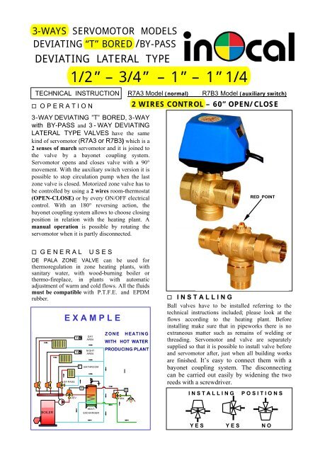
3-WAYS SERVOMOTOR MODELS<br />
DEVIATING “T” BORED /BY-PASS<br />
DEVIATING LATERAL TYPE<br />
�� O P E R A T I O N<br />
BOYLER<br />
BOILER<br />
BY PASS<br />
1/2” – 3/4” – 1” – 1”1/4<br />
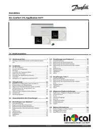
TECHNICAL INSTRUCTION R7A3 Model (normal) R7B3 Model (auxiliary switch)<br />
3-WAY DEVIATING ”T” BORED, 3-WAY<br />
with BY-PASS and 3-WAY DEVIATING<br />
LATERAL TYPE VALVES have the same<br />
kind of servomotor (R7A3 or R7B3) which is a<br />
2 senses of march servomotor and it is joined to<br />
the valve by a bayonet coupling system.<br />
Servomotor opens and closes valve with a 90°<br />
movement. With the auxiliary switch version it is<br />
possible to stop circulation pump when the last<br />
zone valve is closed. Motorized zone valve has to<br />
be controlled by using a 2 wires room-thermostat<br />
(OPEN-CLOSE) or by every ON/OFF electrical<br />
control. With an 180° reversing action, the<br />
bayonet coupling system allows to choose closing<br />
position in relation with the heating plant. A<br />
manual operation is possible by rotating the<br />
servomotor when it is partly disconnected.<br />
�� G E N E R A L U S E S<br />
DE PALA ZONE VALVE can be used for<br />
thermoregulation in zone heating plants, with<br />
sanitary water, with wood-burning boiler or<br />
thermo-fireplace, in plants with automatic<br />
adjustment of warm and cold flows. All the fluids<br />
must be compatible with P.T.F.E. and EPDM<br />
rubber. �� I N S T A L L I N G<br />
Ball valves have to be installed referring to the<br />
E X A M P L E<br />
T<br />
T<br />
DEV.<br />
T<br />
T<br />
DAY<br />
AREA<br />
NIGHT<br />
AREA<br />
BATHROOM<br />
HEAT-<br />
EXCHANGER<br />
ZONE HEATING<br />
WITH HOT WATER<br />
PRODUCING PLANT<br />
MIX.<br />
R<br />
2 WIRES CONTROL – 60” OPEN/CLOSE<br />
RED POINT<br />
technical instructions included; please look at the<br />
flows according to the heating plant. Before<br />
installing make sure that in pipeworks there is no<br />
extraneous matter such as remains of welding or<br />
threading. Servomotor and valve are separately<br />
supplied so that it is possible to install valve before<br />
and servomotor after, just when all building works<br />
are finished. It’s easy to connect them with a<br />
bayonet coupling system. The disconnecting<br />
can be carried out easily by widening the two<br />
reeds with a screwdriver.<br />
I N S T A L L I N G P O S I T I O N S<br />
Y E S Y E S N O
FEATURES OF ZONE BALL VALVE<br />
COMPONENTS<br />
SERVO -<br />
MOTORS<br />
R7A3<br />
or<br />
R7B3<br />
R7A3<br />
or<br />
R7B3<br />
BLUE<br />
BLUE<br />
BLACK<br />
BROWN<br />
( ��<br />
BROWN RED<br />
RED<br />
Y / G<br />
Y / G<br />
OFF<br />
CLOSE<br />
M<br />
M<br />
�<br />
(<br />
N F<br />
BALL<br />
VALVES<br />
633 T/R<br />
633 FL<br />
603 T/R<br />
603 FL<br />
613 T/R<br />
613 FL<br />
623 T/R<br />
623 FL<br />
633 U/S<br />
633 BL<br />
603 U/S<br />
603 BL<br />
613 U/S<br />
613 BL<br />
623 U/S<br />
623 BL<br />
(<br />
)<br />
T<br />
T<br />
ON<br />
OPEN<br />
H<br />
O V E R A L L D I M E N S I O N S<br />
A<br />
min<br />
110 120<br />
110 120<br />
115 125<br />
120 130<br />
B<br />
--<br />
--<br />
--<br />
--<br />
110 120 130<br />
110 120 136<br />
115 125 155<br />
120 130 172<br />
� ELECTRICAL CONNECTIONS<br />
The electric actuator has been equipped with a strong<br />
gear-box and steel gears. The auxiliary switch and a<br />
low rotation time avoid high boiler pressure.<br />
The electric connections of servomotor have to be<br />
connected with the multipolar electric cable (4 or 6<br />
wires) by reading technical instructions above-stated.<br />
The auxiliary switch (GREEN and WHITE) that<br />
stops circulation pump, is a “ CLEAN ” type,<br />
therefore it’s insulated from the control of the valve.<br />
The two wires (GREEN and WHITE) have to be<br />
parallel connected with the power supply of<br />
circulation pump.<br />
The possible hour-meter has to be connected<br />
between OPEN (RED) and NEUTRAL (BLUE)<br />
conductors.<br />
F<br />
76<br />
76<br />
86<br />
94<br />
--<br />
--<br />
--<br />
--<br />
P<br />
38<br />
38<br />
43<br />
47<br />
65<br />
68<br />
78<br />
86<br />
W I D T H 63<br />
R 7 A 3 R 7 B 3<br />
AUXILIARY SWITCH<br />
BLUE<br />
M<br />
��<br />
N F<br />
)<br />
�(<br />
WÄRMETECHNIK Gesellschaft m.b.H.<br />
OFF<br />
BROWN<br />
ON<br />
RED<br />
T<br />
Y / G<br />
GREEN<br />
5 (1) A<br />
F<br />
WHITE<br />
N<br />
BALL VALVES 633 603 613 623<br />
• Valve body : BRASS CW617N (UNI 12165)<br />
• Ball : BRASS CW617N (nichel-chromium plated)<br />
• Rod : EXTRUDED OT CW614N (UNI 12164)<br />
• SEALS on the ball and on the rod : P.T.F.E. and<br />
E EPDM O-RINGS<br />
• Nominal operating pressure : 10 bar<br />
• Maximum differential operating pressure : 6bar<br />
• Fluid temperature field : FROM 0 °C to 100 °C<br />
• Utilisable fluids : WATER or Fluids compatible<br />
w with PTFE and EPDM rubber<br />
• Attachments : Internal GAS or Flat sealing union<br />
a attachments<br />
• Load loss : no effect (TOTAL FLOW TYPE )<br />
SERVOMOTORS R7A3 – R7B3<br />
• Supply voltage : 230 V 50 Hz<br />
• Absorbed power : 4 VA<br />
• Torque on the control rod : 7 Nm (70 Kg ¥ cm)<br />
• Ambient operating temperature : 0 °C ÷ 65 °C<br />
• Opening or closing time : 60 sec.<br />
• Type of control : 2 wires control – ON/OFF type<br />
• Auxiliary contact capability : 5A 250V<br />
• Electrical protection level : IP 54<br />
• Cable length : 1000 mm<br />
PUSH<br />
TO<br />
CONNECT<br />
WIDE THE<br />
TWO REEDS TO<br />
DISCONNECT<br />
Friedhofstraße 4; A-4020 Linz<br />
Tel. : 0043(0)732/650391-0<br />
Fax. : 0043(0)732/650392-10<br />
info@inocal.com ; www.inocal.com
3-WAYS SERVOMOTOR MODELS<br />
DEVIATING “T” BORED /BY-PASS<br />
DEVIATING LATERAL TYPE<br />
�� O P E R A T I O N<br />
BOYLER<br />
BOILER<br />
BY PASS<br />
1/2” – 3/4” – 1” – 1”1/4<br />
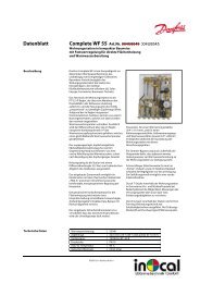
TECHNICAL INSTRUCTION M73AN Model (normal) M73BN Model (auxiliary switch)<br />
3-WAY DEVIATING ”T” BORED, 3-WAY<br />
with BY-PASS and 3-WAY DEVIATING<br />
LATERAL TYPE VALVES have the same<br />
kind of servomotor (M7A3N or M7B3N)<br />
which is a 2 senses of march servomotor and it is<br />
joined to the valve by a bayonet coupling system.<br />
Servomotor opens and closes valve with a 90°<br />
movement. With the auxiliary switch version it is<br />
possible to stop circulation pump when the last<br />
zone valve is closed. Motorized zone valve has to<br />
be controlled by using a 3 wires room-thermostat<br />
(COMMON-OPEN-CLOSE) or by every<br />
deviating electrical control. With an 180°<br />
reversing action, the bayonet coupling system<br />
allows to choose closing position in relation with<br />
the heating plant. A manual operation is<br />
possible by rotating the servomotor when it is<br />
partly disconnected.<br />
�� G E N E R A L U S E S<br />
DE PALA ZONE VALVE can be used for<br />
thermoregulation in zone heating plants, with<br />
sanitary water, with wood-burning boiler or<br />
thermo-fireplace, in plants with automatic<br />
adjustment of warm and cold flows. All the fluids<br />
must be compatible with P.T.F.E. and EPDM<br />
rubber. �� I N S T A L L I N G<br />
Ball valves have to be installed referring to the<br />
E X A M P L E<br />
T<br />
T<br />
DEV.<br />
T<br />
T<br />
DAY<br />
AREA<br />
NIGHT<br />
AREA<br />
BATHROOM<br />
HEAT-<br />
EXCHANGER<br />
ZONE HEATING<br />
WITH HOT WATER<br />
PRODUCING PLANT<br />
MIX.<br />
R<br />
3 WIRES CONTROL – 60” OPEN/CLOSE<br />
RED POINT<br />
technical instructions included; please look at the<br />
flows according to the heating plant. Before<br />
installing make sure that in pipeworks there is no<br />
extraneous matter such as remains of welding or<br />
threading. Servomotor and valve are separately<br />
supplied so that it is possible to install valve before<br />
and servomotor after, just when all building works<br />
are finished. It’s easy to connect them with a<br />
bayonet coupling system. The disconnecting<br />
can be carried out easily by widening the two<br />
reeds with a screwdriver.<br />
I N S T A L L I N G P O S I T I O N S<br />
Y E S Y E S N O
FEATURES OF ZONE BALL VALVE<br />
COMPONENTS<br />
SERVO -<br />
MOTORS<br />
M7A3N<br />
or<br />
M7B3N<br />
M7A3N<br />
or<br />
M7B3N<br />
BALL<br />
VALVES<br />
633 T/R<br />
633 FL<br />
603 T/R<br />
603 FL<br />
613 T/R<br />
613 FL<br />
623 T/R<br />
623 FL<br />
633 U/S<br />
633 BL<br />
603 U/S<br />
603 BL<br />
613 U/S<br />
613 BL<br />
623 U/S<br />
623 BL<br />
H<br />
O V E R A L L D I M E N S I O N S<br />
A<br />
min<br />
110 120<br />
110 120<br />
115 125<br />
120 130<br />
B<br />
--<br />
--<br />
--<br />
--<br />
110 120 130<br />
110 120 136<br />
115 125 155<br />
120 130 172<br />
BLUE<br />
BLACK<br />
CLOSE<br />
M<br />
☼ i(ii (<br />
☼(<br />
N P<br />
RED<br />
T<br />
OPEN<br />
Y / G<br />
GREEN<br />
5 (1) A<br />
WHITE<br />
P N<br />
� ELECTRICAL CONNECTIONS<br />
The electric actuator has been equipped with a strong<br />
gear-box and steel gears. The auxiliary switch and a<br />
low rotation time avoid high boiler pressure.<br />
The electric connections of servomotor have to be<br />
connected with the multipolar electric cable (4 or 6<br />
wires) by reading technical instructions above-stated.<br />
The auxiliary switch (GREEN and WHITE) that<br />
stops circulation pump, is a “ CLEAN ” type,<br />
therefore it’s insulated from the control of the valve.<br />
The two wires (GREEN and WHITE) have to be<br />
parallel connected with the power supply of<br />
circulation pump.<br />
The possible hour-meter has to be connected<br />
between OPEN (RED or BROWN) and NEUTRAL<br />
(BLUE) conductors.<br />
F<br />
76<br />
76<br />
86<br />
94<br />
--<br />
--<br />
--<br />
--<br />
P<br />
38<br />
38<br />
43<br />
47<br />
65<br />
68<br />
78<br />
86<br />
W I D T H 63<br />
M 7 A 3 N M 7 B 3 N<br />
AUXILIARY SWITCH<br />
BLUE<br />
BLACK<br />
CLOSE<br />
M<br />
(<br />
(<br />
N P<br />
BROWN RED<br />
T<br />
Y / G<br />
OPEN<br />
WÄRMETECHNIK Gesellschaft m.b.H.<br />
BALL VALVES 633 603 613 623<br />
• Valve body : BRASS CW617N (UNI 12165)<br />
• Ball : BRASS CW617N (nichel-chromium plated)<br />
• Rod : EXTRUDED OT CW614N (UNI 12164)<br />
• SEALS on the ball and on the rod : P.T.F.E. and<br />
E EPDM O-RINGS<br />
• Nominal operating pressure : 10 bar<br />
• Maximum differential operating pressure : 6bar<br />
• Fluid temperature field : FROM 0 °C to 100 °C<br />
• Utilisable fluids : WATER or Fluids compatible<br />
w with PTFE and EPDM rubber<br />
• Attachments : Internal GAS or Flat sealing union<br />
a attachments<br />
• Load loss : no effect (TOTAL FLOW TYPE )<br />
SERVOMOTORS M7A3N – M7B3N<br />
• Supply voltage : 230 V 50 Hz<br />
• Absorbed power : 4 VA<br />
• Torque on the control rod : 7 Nm (70 Kg ¥ cm)<br />
• Ambient operating temperature : 0 °C ÷ 65 °C<br />
• Opening or closing time : 60 sec.<br />
• Type of control : 3 wires control – deviating type<br />
• Auxiliary contact capability : 5A 250V<br />
• Electrical protection level : IP 54<br />
• Cable length : 1000 mm<br />
PUSH<br />
TO<br />
CONNECT<br />
WIDE THE<br />
TWO REEDS TO<br />
DISCONNECT<br />
Friedhofstraße 4; A-4020 Linz<br />
Tel. : 0043(0)732/650391-0<br />
Fax. : 0043(0)732/650392-10<br />
info@inocal.com ; www.inocal.com
.<br />
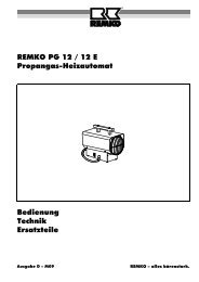
3-WAY MOTORIZED VALVE<br />
DEVIATING “T” BORED<br />
TECHNICAL INSTRUCTION<br />
� FUNZIONAMENTO<br />
� O P E R A T I O N<br />
Valvola 3 vie MIXELATRICE con otturatore sfera dotato di<br />
passaggio triplo disposto a “T” che permette una entrata<br />
centrale 3-WAY A e VALVE due uscite with laterali a B e “T” C. bored ball which<br />
Utilizzata come DEVIATRICE: il flusso d’entrata dalla via<br />
centrale departs A viene at the deviato same su time quelle the laterali flow B from e C,<br />
bilanciandone il rapporto a discrezione senza soluzione di<br />
central way A to lateral ones B C.<br />
continuità fino al limite del TUTTO-NIENTE.<br />
Utilizzata come MIXELATRICE: con due flussi di entrata<br />
laterali If it B is e C used ed uno as centrale a deviating A di uscita valve può espletare the main una<br />
azione flow is di deviated miscelazione to lateral a punto ones fisso and qualora so that il suo it<br />
servomotore venga comandato da un segnale ad impulsi in<br />
deviazione is possible con zero to calculate centrale. the ratio between Comandato the da<br />
un termostato ambiente a tre contatti (Apre-Comune-Chiude)<br />
il servomotore two positions. arresta la rotazione della valvola nelle posizioni<br />
di totale chiusura per la via B-A o per la via C-A.<br />
Il If servomotore it is used elettrico as a mixing abbinabile valve, ha and una so rotazione there<br />
bidirezionale ed è innestato con un sistema a baionetta;<br />
ha are una indicazione two entrances esterna della and posizione one exit, di valvola the chiusa valveo<br />
aperta performs quando questa a set-point è montata mixing sull’impianto. action; in this<br />
Può essere azionata da servomotori (CODICE M7..) che<br />
necessitano case the di servomotor COMANDO must A TRE be FILI: controlled per esempio by<br />
termostati con contatto in deviazione. Oppure sono disponibili<br />
pulse modulation system with delivery filler.<br />
servomotori con relè interno (CODICE R7..) i quali<br />
necessitano di COMANDO A DUE FILI.<br />
Per The ogni motorized tipo di servomotore zone valve esiste (Code la versione M7..) con is<br />
microinterruttore designed for ausiliario, operation con contatto by 3 wires elettrico room di tipo<br />
“pulito”, che permette di far funzionare il circolatore solo<br />
quando thermostat la valvola è (COMMON-OPEN-CLOSE) in posizione di totale apertura. or<br />
L’ azionamento manuale della valvola si ottiene<br />
ruotando by every il motore deviating parzialmente electrical control. disinnestato.<br />
� If you IMPIEGO need a 2 wire CONTROL (ON-OFF)<br />
Come valvola di regolazione della temperatura negli impianti<br />
there is a special servomotor (Code R7..)<br />
di riscaldamento a zona, negli impianti con caldaia a legna o<br />
con with termocaminetti, an internal relay. negli impianti di intercettazione<br />
automatica ON-OFF di fluidi caldi o freddi e comunque<br />
compatibili chimicamente con le tenute della valvole.<br />
HOW TO CONNECT OR DISCONNECT<br />
A SERVOMOTOR TO A BALL VALVE<br />
PUSH<br />
TO<br />
CONNECT<br />
Models 633T – 603T – 613T – 623T ( FEMALE )<br />
633U – 603U – 613U – 623U (PIPE UNIONS)<br />
WIDE THE<br />
TWO REEDS TO<br />
DISCONNECT<br />
ROD<br />
POSITION<br />
FLOWS<br />
BALL<br />
VALVE<br />
MODELS<br />
RED POINT<br />
B C B C B C<br />
OPEN A B<br />
CLOSED A C<br />
A A A<br />
OPEN A B<br />
OPEN A C<br />
RED POINT<br />
ATTACHMENTS FEMALE PIPE-UNIONS<br />
The ball valve has to be fitted up with 3 rd � INSTALLING<br />
way<br />
A connected to the main flow. .<br />
If it is used as deviating valve, the pump has<br />
to be installed after the motorized valve; if it<br />
is used as mixing valve, the pump has to be<br />
installed before the motorized valve.<br />
There are two red points on the control rod<br />
and they indicate the open ways, so that it is<br />
possible to set the zone valve in relation with<br />
the heating plant. .<br />
Before installing make sure that in pipeworks<br />
there is no extraneous matter such as remains<br />
of welding or threading.<br />
I N S T A L L I N G P O S I T I O N S<br />
YES YES NO<br />
OPEN A B<br />
CLOSED A C<br />
1/2 ” 633 T 633 U<br />
3/4 ” 603 T 603 U<br />
1 ” 613 T 613 U<br />
1” 1/4 623 T 623 U
FEATURES OF 3-WAYS ZONE BALL VALVE<br />
3 -WAYS DEVIATING “T” BORED<br />
MODELS OVERALL DIMENTIONS<br />
BALL<br />
VALVE<br />
H A min. B F P<br />
633 T 110 120 - 76 38<br />
603 T 110 120 - 76 38<br />
613 T 115 125 - 86 43<br />
623 T 120 130 - 94 47<br />
633 U 110 120 130 - 65<br />
603 U 110 120 136 - 68<br />
613 U 115 125 155 - 78<br />
623 U 120 130 172 - 86<br />
BALL VALVES 633 – 603 – 613 – 623<br />
� • Valve body : BRASS CW617N (UNI 12165)<br />
Corpo valvola : Ottone OT 58 ( UNI 5705 )<br />
• Ball : BRASS CW617N (nichel-chromium plated)<br />
� Sfera : Ottone OT 58 ( Cromata )<br />
• Rod : EXTRUDED OT CW614N (UNI 12164)<br />
� Sedi Sfera : PTFE più O-RING in EPDM<br />
• SEALS on the ball and on the rod : P.T.F.E. and<br />
�<br />
E Asta : Ottone OT 58 ( UN I 5705 EPDM ) O-RINGS<br />
� • Nominal Asta di operating manovra pressure con doppio : 10 O-RING bar in EPDM<br />
� • Maximum differential ed operating anello di pressure tenuta : 6 in bar PTFE<br />
� • Fluid Pressione temperature massima field di : FROM esercizio 0 °C : TO 10 bar 100 °C<br />
� • Utilisable fluids : WATER or Fluids which are<br />
Pressione differenziale massima : Δp = 6 bar<br />
c compatible with PTFE and EPDM rubber<br />
� Temperatura di esercizio del fluido : 0 ÷ + 100 °C<br />
• Attachments : Internal GAS or Flat sealing union a<br />
� Fluido utilizzabile : Acqua o liquidi compatibili con<br />
a attachments<br />
• Load loss : no effect tenute (TOTAL in FLOW TEFLON TYPE ed ) EPDM<br />
� Perdite di carico : pressochè nulle<br />
COUPLED SERVOMOTORS<br />
3 – WAY<br />
BALL VALVE<br />
MIXING TYPE<br />
TYPE OF<br />
CONTROLS<br />
AUXILIARY<br />
SWITCH<br />
CODE<br />
LOAD LOSS Δp (daPa ≅ mm H2O)<br />
3 WIRES NO M7A3N<br />
3 WIRES SINGLE M7B3N<br />
2 WIRES NO R7A3<br />
2 WIRES SINGLE<br />
WÄRMETECHNIK Gesellschaft m.b.H.<br />
R7B3<br />
5.000<br />
3.000<br />
2.000<br />
1.000<br />
500<br />
BY PASS<br />
300<br />
BY PASS<br />
200<br />
100<br />
50<br />
30<br />
20<br />
3/4”<br />
H<br />
1”<br />
WIDTH 63<br />
1/2”<br />
3/4”<br />
1”<br />
1” 1/4<br />
10<br />
100 200 300 500 1.000 2.000 3.000 5.000 10.000 20.000<br />
ELECTRICAL<br />
CONNECTIONS<br />
READ THE<br />
INSTRUCTION<br />
INCLUDED WITH<br />
THE SERVOMOTOR<br />
READ THE<br />
INSTRUCTION<br />
INCLUDED WITH<br />
THE SERVOMOTOR<br />
F<br />
B<br />
FLOW RATE Q (l/h)<br />
POWER SUPPLY<br />
230V - 50 Hz<br />
on request<br />
24V - 50Hz<br />
A min<br />
Friedhofstraße 4; A-4020 Linz<br />
Tel. : 0043(0)732/650391-0<br />
Fax. : 0043(0)732/650392-10<br />
info@inocal.com ; www.inocal.com<br />
P