Panels by finite elements SCN - Nemetschek Frilo
Panels by finite elements SCN - Nemetschek Frilo
Panels by finite elements SCN - Nemetschek Frilo

Create successful ePaper yourself
Turn your PDF publications into a flip-book with our unique Google optimized e-Paper software.
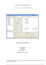
<strong>Panels</strong> <strong>by</strong> <strong>finite</strong> <strong>elements</strong> <strong>SCN</strong><br />
User manual for <strong>Frilo</strong> design calculation applications<br />
© Friedrich + Lochner GmbH 2010<br />
<strong>Frilo</strong> on the web<br />
www.frilo.de<br />
E-Mail: info@frilo.de<br />
<strong>SCN</strong> Manual, revision 1/2010<br />
<strong>SCN</strong> - <strong>Panels</strong> <strong>by</strong> <strong>finite</strong> <strong>elements</strong> 1
<strong>Frilo</strong> Application: <strong>SCN</strong> - <strong>Panels</strong> <strong>by</strong> <strong>finite</strong> <strong>elements</strong><br />
This manual deals with the basic features of the <strong>SCN</strong> application.<br />
Table of contents<br />
Application options............................................................................................................... 3<br />
Basis of calculation .............................................................................................................. 5<br />
Input ....................................................................................................................................... 6<br />
Graphical input..................................................................................................................... 6<br />
Numeric input....................................................................................................................... 6<br />
DXF import........................................................................................................................... 6<br />
System and load input ......................................................................................................... 6<br />
Result sections ..................................................................................................................... 7<br />
FE-mesh................................................................................................................................. 8<br />
Properties ............................................................................................................................ 8<br />
Generation ........................................................................................................................... 8<br />
Delete .................................................................................................................................. 8<br />
Calculation/superposition... ................................................................................................. 9<br />
Design: Settings.................................................................................................................. 11<br />
Superposition..................................................................................................................... 11<br />
Panel design ...................................................................................................................... 12<br />
Crack widths ... .................................................................................................................. 13<br />
Results: Superpositions..................................................................................................... 14<br />
Results: Settings................................................................................................................. 14<br />
Grid.................................................................................................................................... 14<br />
Scaling............................................................................................................................... 14<br />
Output & results.................................................................................................................. 15<br />
<strong>SCN</strong> output profile .............................................................................................................. 19<br />
Application-specific icons.................................................................................................. 20<br />
Additional menus in <strong>SCN</strong> ................................................................................................... 21<br />
Edit menu........................................................................................................................... 21<br />
Results menu..................................................................................................................... 21<br />
Options menu .................................................................................................................... 22<br />
Input menu......................................................................................................................... 22<br />
Graphic options menu........................................................................................................ 22<br />
Tools menu ........................................................................................................................ 23<br />
Graphical input.................................................................................................................... 24<br />
Three-dimensional construction graph............................................................................. 24<br />
Literatur ............................................................................................................................... 24<br />
You will find the documentation of the graphical input in the following manual:<br />
Graphical input.pdf Graphical input for programs GEO, PLT, SC7, <strong>SCN</strong> and WL<br />
2 <strong>Frilo</strong> - Structural analysis and design
Application options<br />
The <strong>SCN</strong> application is based on graphic features and supports the calculation of loadbearing<br />
panel structures with complex bearing conditions or load arrangements that can<br />
hardly be handled using traditional approximation methods.<br />
The graphical input module offers numerous new functions and options that provide for a<br />
quick and comfortable system generation and give a detailed system overview at the same<br />
time.<br />
This application is particularly suitable for the structural calculation of walls and wall-type<br />
girders and their design in accordance with the BAUMANN method (/4/, /6/).<br />
Load-bearing structures are substantially considered as panels if the following relations exist<br />
between the typical system dimensions system length L and cross sectional height H:<br />
Cantilever: L / H < 1,<br />
Single-span girder: L / H < 2,<br />
Multi-span girder: L / H < 2.5.<br />
The panel is a plane load-bearing structure to which the external forces apply in its plane<br />
and generate an evenly distributed membrane state of stress. Effects of actions<br />
perpendicular to this plane are excluded (flexural effects � slab).<br />
As long as the states of equilibrium in the plane of the structure and those perpendicular to it<br />
may be considered in undeformed condition, the two bearing effects can be examined<br />
separately from each other. Problems of stability and bracing are not treated.<br />
The restricting assumptions of the beam theory such as the Euler-Bernoulli hypothesis, the<br />
equality of the cross sectional shifts of all points in the same cross sectional plane and the<br />
disregard of the orthogonal axial stress �y perpendicular to the system axis can be<br />
dispensed with in the panel theory. According to the panel theory, shear stress does not only<br />
result from equilibrium considerations as in the beam theory but also from a fully valid<br />
stress/distortion relationship.<br />
Examples for the application of panels are wall bracings in high-rise buildings, wall-type<br />
girder systems and corbels. In the current version, you cannot couple panels and single<br />
bars, which means that you must discretise bars as panel <strong>elements</strong> (drawback: great shear<br />
deformations).<br />
Standards<br />
- DIN 1045<br />
- DIN 1045-1 (2001 + 2008)<br />
- ÖNorm B 4700<br />
- EC2 Italien<br />
- EN 1992 1-1, NA-D/AT/GB<br />
Note: Europen standard - national annex<br />
Included in the program list price is one<br />
national annex - generally the one of the<br />
customer country. National annexes of<br />
further countries can be bought as<br />
additional option..<br />
Interfaces to CAD systems<br />
You can import/export DXF files with auxiliary structures for instance.<br />
Formwork drawings from CAD systems make Glaser (ISB-CAD) can be imported and edited.<br />
Formwork drawings from <strong>Nemetschek</strong>-Allplan can also be imported via the ASCII interface.<br />
The transfer of reinforcement calculation results to ISB-CAD or <strong>Nemetschek</strong>-CAD is handled<br />
via direct interfaces.<br />
<strong>SCN</strong> - <strong>Panels</strong> <strong>by</strong> <strong>finite</strong> <strong>elements</strong> 3
ASCII interface<br />
Interface for the export/import of system data.<br />
Restrictions<br />
- Only one material per slab is admitted.<br />
- A linearly elastic calculation (state 1) is performed.<br />
- Sheet stresses are not available.<br />
4 <strong>Frilo</strong> - Structural analysis and design
Basis of calculation<br />
The calculation is performed in accordance with the <strong>finite</strong> <strong>elements</strong> method and based on<br />
the theory of elasticity. The design of the reinforced concrete panel is performed in<br />
accordance with the BAUMANN method for an orthogonal reinforcement mesh. The<br />
structural calculation of a reinforced concrete panel is based on the uncracked state I. For<br />
the elasticity values those of the concrete are assumed.<br />
Approximation methods such as <strong>finite</strong> <strong>elements</strong> satisfy equilibrium conditions related to the<br />
<strong>finite</strong> element <strong>by</strong> calculating the arithmetic average of all stress states. Therefore, stress<br />
concentrations in the individual <strong>elements</strong> can only be represented incompletely with the<br />
usual methods of discretisation. A local refinement of the mesh would improve the results in<br />
these areas under normal conditions. In view of the discontinuous distribution of the<br />
reinforcement, this is however not imperative. In addition to this, the refinement of the mesh<br />
involves the risk of unfavourable element proportions that falsify the results for numerical<br />
reasons. It is the task of the engineer to find a compromise and evaluate the individual<br />
results.<br />
The calculation method alone does not reveal how far the results are from reality. The only<br />
way to find this out is to estimate it <strong>by</strong> finer discretisation. We recommend you to select at<br />
least 10 <strong>elements</strong> between two points of discontinuity (bearings).<br />
In the current version, the application uses two-dimensional squared <strong>elements</strong>. These<br />
<strong>elements</strong> are very efficient in regard to the computing time. The accuracy of the results is<br />
very high due to the higher-order shift approach for u(x,y) and v(x,y). Considerable variations<br />
occur in the area of discontinuities, in combination with local stress variations in the proximity<br />
of bearings, for instance. Comparative calculations show that the deformation results of this<br />
type of element deviate from the more accurate results <strong>by</strong> 10 % maximum if discretisation is<br />
sufficiently fine.<br />
With a finer subdivision, this element produces even more accurate results. The element's<br />
lengths relations should however not exceed the ratio of 2 to 1.<br />
Mesh generator<br />
The implemented mesh generator works according to the "Advancing Front Method". It is<br />
suitable for mesh generation with two-dimensional objects of any shape.<br />
First, nodes are generated along the default lines. After this, squared <strong>elements</strong> are<br />
successively generated at several active fronts . During the generation of the <strong>elements</strong>, the<br />
quality of each newly generated element is examined and optimised.<br />
Design<br />
The design of the reinforcement is performed in accordance with the Baumann method. A<br />
cracked panel element is used as a model. The direction of the cracks results from the<br />
condition that the deformation energy produced <strong>by</strong> the reaction forces must become a<br />
minimum. The design approach assumes an orthogonal mesh reinforcement in the first<br />
place.<br />
<strong>SCN</strong> - <strong>Panels</strong> <strong>by</strong> <strong>finite</strong> <strong>elements</strong> 5
Input<br />
Graphical input<br />
The <strong>SCN</strong> application offers a graphical user interface, i.e. <strong>elements</strong> such as the plate outline,<br />
load coordinates etc. are drawn with the help of the mouse on the basis of a DXF file, for<br />
instance, and only particular values, such as those of forces, have to be entered numerically<br />
in corresponding dialogs.<br />
The user can see the defined graphic objects immediately on the screen. The hide/display<br />
options for individual <strong>elements</strong> such as load arrangements provide for a well-structured<br />
overview of even highly complex systems.<br />
The "Graphical input" is an independent application module that is linked to the <strong>SCN</strong><br />
application. The functions of the Graphical input module are described in a separate<br />
document Graphical input.pdf.<br />
Numeric input<br />
Of course, you can enter values and coordinates any time via numeric input fields if you want<br />
to make a precise numerical specification. How to do this is described in the document<br />
Graphical input.pdf.<br />
Note: Direct help and support referring to the current input operation is given in the<br />
form of a short comment in the status line on bottom left of the screen.<br />
DXF import<br />
You can import geometrical data providing the basis for the system definition via the<br />
DXF interface. Glaser files (-isb CAD interface) and <strong>Nemetschek</strong> CAD files (ASCII interface)<br />
can be processed directly.<br />
System and load input<br />
The system and load input functions are part of the "Graphical input" module and are<br />
described in detail in the document Graphical input.pdf.<br />
The definition of a system starts with the input of the slab outline and the definition of the<br />
basic parameters.<br />
Material, standard selection, panel thickness, concrete coverage and details concerning the<br />
serviceability, if required.<br />
Note: In the current version you can only use isotropic materials for the calculation.<br />
Various drawing functions are available for the definition of an outline and block-outs as well<br />
as loads and auxiliary lines. They are accessible via icons that can be activated per mouse<br />
click. There are icons for the input of lines, rectangles, polygons and circles. The definition of<br />
these outlines, i.e. the input of decisive coordinates, lengths and radii is done per mouse<br />
click under normal conditions. You can however always enter individual or all coordinates<br />
numerically via the keyboard.<br />
6 <strong>Frilo</strong> - Structural analysis and design
Result sections<br />
Access via the main tree � Result sections<br />
This function allows you to define result sections. After the calculation, you can display the<br />
action-effects, the deformation behaviour, the base compression behaviour (for bedded<br />
slabs) as well as the behaviour of the values indicating the cross section of the longitudinal<br />
reinforcement.<br />
Enter a section as a polygon line. Define your polygonal section line with the help<br />
of the mouse or via the numeric input. Finish the operation per right click and select<br />
"Exit".<br />
Edit the course of a section subsequently. Click on the corresponding section and<br />
drag the corner points to the desired target positions using the mouse. Finish the<br />
operation per right click and select "Exit".<br />
Move a section line. Click on the corresponding section and drag it to the desired<br />
target position with the help of the mouse . Finish the operation per right click and<br />
select "Exit".<br />
Move a section line. Click on the corresponding section and drag the copy with the<br />
help of the mouse to the desired target position. Finish the operation per right click<br />
and select "Exit".<br />
Delete a section or several sections (one after the other). Finish the deleting<br />
operation with a right click and select "Exit".<br />
<strong>SCN</strong> - <strong>Panels</strong> <strong>by</strong> <strong>finite</strong> <strong>elements</strong> 7
FE-mesh<br />
See also � Basis of calculation<br />
Properties<br />
You can define various basic settings relevant<br />
for the generation of the FE mesh in this<br />
section:<br />
Element dimensions Specify the desired<br />
(average) element<br />
size (edge length)<br />
for the automatic<br />
mesh generation.<br />
If the mesh cannot<br />
be generated with<br />
this size it is reduced<br />
automatically.<br />
Tip: You should<br />
always select the<br />
size for the FE mesh in such a manner that the deformation line<br />
comes close to reality, i.e. each field should at least have six<br />
<strong>elements</strong>.<br />
Minimum edge length You can define the minimum element edge length. The edge length<br />
used for mesh generation must not fall below this value. If smaller<br />
<strong>elements</strong> are required, the mesh generation is aborted and a<br />
corresponding message is displayed.<br />
Element results... This option allows you to select the points at which element results<br />
should be calculated.<br />
You can select among the following design points:<br />
- centre points of the <strong>elements</strong><br />
- centre points of the element sides (default)<br />
- corner points of the <strong>elements</strong><br />
Note: The option "Corner points of <strong>elements</strong>" can produce<br />
unfavourable results in so-called points of singularity.<br />
Note: In the current version of the application, the FE mesh also includes the position<br />
of all applying loads in the calculation. Therefore, the FE mesh which is<br />
generated without loads for verification purposes may differ from the FE mesh<br />
that is used for the calculation.<br />
Generation<br />
This menu item launches the generation of the FE mesh based on the values and options<br />
set in the "FE mesh properties" dialog. Alternatively, you can click on the icon to<br />
generate the FE mesh.<br />
Delete<br />
This menu item allows you to delete an existing FE mesh. Alternatively, you can click on the<br />
icon to delete it.<br />
8 <strong>Frilo</strong> - Structural analysis and design
Calculation/superposition...<br />
Calculate Tick/untick this option to select the load cases that should be included<br />
in the calculation.<br />
Calculated You can see in this column whether a load case has already been<br />
calculated.<br />
Incl. selfweight Tick this option if the selfweight should be considered in the<br />
calculation.<br />
Superposition Tick the load cases that should be considered for the superposition.<br />
Alternative group Load cases of the same alternative group exclude each other.<br />
You can enter load cases that cannot occur simultaneously with the<br />
help of so-called alternative groups.<br />
Example: Wind from the left or the right, load position of a fork lift.<br />
Loads of the alternative group "0" may occur in combination with all<br />
other load cases.<br />
All load cases of an alternative group (marked with the same number)<br />
exclude each other.<br />
Obviously, only load cases from non-permanent actions can be<br />
members of alternative groups.<br />
The alternative groups are considered after the calculation in the<br />
course of the superposition of the results. Therefore, they can only be<br />
used for linear calculation (i.e. no tension spring exclusion).<br />
Example of an alternative group<br />
The load cases 1 and 2 are assigned to alternative group 1 because<br />
the fork lift is either in field 1 or in field 2.<br />
EN 1992 1-1 (NA D/AT/GB), DIN 1045-1 : 2004/2008<br />
Partial safety This section displays partial safety factors depending on the selected<br />
type of action (permanent or non-permanent).<br />
Action Select the desired type of action from the selection list.<br />
Leading action In the superposition, the leading action is considered for each location<br />
and each action-effect.<br />
A subsequent superposition of the individual results cannot be<br />
performed for non-linear calculations. Therefore, the leading action<br />
<strong>SCN</strong> - <strong>Panels</strong> <strong>by</strong> <strong>finite</strong> <strong>elements</strong> 9
must be determined in advance. The last column of the leading action<br />
is only enabled for non-linear calculations.<br />
Note: The current version does not include the non-linear calculation<br />
of panels. Therefore, the last column of the leading action is not<br />
enabled.<br />
B4700 und EC2 Italien<br />
The afore-mentioned statements apply analogously to the Austrian standard B4700 and the<br />
Italian EC2.<br />
DIN 1045 7/88<br />
Permanent Permanent load (e.g. selfweight)<br />
Non-permanent Non-permanent load (e.g. live load)<br />
The application searches the relevant load combination (e. g. g or<br />
g+p) for each design point.<br />
The application cannot consider a load per field automatically. If the<br />
live load should be assumed per field, a separate load case must be<br />
generated for each field (or a checkered distribution).<br />
If the live load is defined over the total surface, the field reinforcement<br />
must be increased <strong>by</strong> constructive measures in systems with multiple<br />
fields.<br />
Factor You can specify a multiplying factor for the respective load case in this<br />
column.<br />
The calculation is launched when you confirm your settings in this window with OK.<br />
10 <strong>Frilo</strong> - Structural analysis and design
Design: Settings<br />
The section Design - Settings offers various options and settings depending on the selected<br />
standard.<br />
Superposition<br />
In the standardised design situations of the ultimate limit state it has been defined which<br />
action groups in which situation has to be considered<br />
The so called “characteristic” superposition does not correspond to the standardised design<br />
situations, but is a simple superposition without partial safety- and combination coefficients.<br />
Thus for the characteristic superposition we provide the following options, so you can define<br />
which action types should be taken into account. In this way you can compare the influences<br />
of different actions.<br />
- All non-permanent actions<br />
- Accidental actions<br />
- Earthquake<br />
<strong>SCN</strong> - <strong>Panels</strong> <strong>by</strong> <strong>finite</strong> <strong>elements</strong> 11
Panel design<br />
Compressive Tick this option to consider possibly required compressive<br />
reinforcement reinforcement when the compressive strength of the concrete is<br />
exceeded. This reinforcement might be required in load introduction<br />
areas or smaller bearing areas.<br />
The compressive reinforcement is marked with an exclamation mark<br />
(!) in the output grid.<br />
Minimum Tick this option to include minimum reinforcement for wall-type<br />
reinforcement girders.<br />
Note: This option does not refer to a minimum reinforcement ensuring<br />
stability. You must perform the stability analysis separately if required.<br />
Design direction The horizontal and vertical directions are set as default global<br />
design directions. You can however freely select the global design<br />
directions according to your requirements.<br />
12 <strong>Frilo</strong> - Structural analysis and design
Crack widths ...<br />
DIN 1045-1 : 2004/2008<br />
In accordance with DIN 1045-1, the<br />
calculation of the existing crack width<br />
and/or the permissible limit diameter of the<br />
longitudinal reinforcement depends on the<br />
percentage of the flexural tension<br />
reinforcement (para. 11.2.3 and 11.2.4).<br />
For the determination of the percentage of<br />
reinforcement you can either select the<br />
reinforcement required <strong>by</strong> the bending<br />
design or a default reinforcement to be<br />
specified. If the option "default flexural<br />
tension reinforcement" is ticked, always the<br />
higher reinforcement value of the statically<br />
required and the default reinforcement is<br />
used.<br />
In addition, you can increase the flexural<br />
tension reinforcement until the crack width<br />
proof criteria are complied with via the<br />
option "Increase flexural tension<br />
reinforcement".<br />
Note: Ticking the option "Increase reinforcement" may produce different results on the<br />
front and rear side of the panel in particular cases if the durability requirements<br />
to be satisfied differ for each side. In these cases, a separate output of the<br />
results for the front and rear side is available.<br />
EN 1992 1-1 (NA D/AT/GB)<br />
The options and settings described for DIN 1045-1 apply analogously to this standard.<br />
Austrian standard B4700<br />
This option is not enabled for this standard.<br />
EC2 Italy<br />
The options and settings described for DIN 1045-1 apply analogously to this standard.<br />
DIN 1045 superseded<br />
This option is not enabled for this standard.<br />
<strong>SCN</strong> - <strong>Panels</strong> <strong>by</strong> <strong>finite</strong> <strong>elements</strong> 13
Results: Superpositions<br />
All results of each required design situation can be displayed and put out.<br />
If the nature of the effects of actions requires you to examine more than one design situation,<br />
such as the "permanent/transient" and the "accidental" situations in the ultimate limit state<br />
(ULS) and the "quasi-permanent" situation in the serviceability limit state (SLT), the<br />
application generates a decisive superposition of all design situations involved.<br />
In addition to the design situation prescribed <strong>by</strong> the standards a so-called characteristic<br />
superposition is performed. It consists in a simple superposition without partial safety and<br />
combination coefficients.<br />
Results: Settings<br />
Grid<br />
"Results - Grid" menu<br />
Orientation<br />
The orientation (angle) of the output<br />
grid depends on the value set for the<br />
reinforcement area. If several areas<br />
with different orientations are defined<br />
or the defined reinforcement areas do<br />
not cover the entire slab, you can<br />
switch over between the different<br />
angles in this section. The grid shows<br />
only the areas with results for the<br />
corresponding angle. Areas for which<br />
no rotated reinforcement area was<br />
defined are consequently shown when<br />
you select the orientation 0 [°].<br />
Cell size<br />
You can define the spacing of grid lines in this section.<br />
Reinforcement<br />
You can select whether the reinforcement areas to be put out should include the total<br />
reinforcement, the difference between the total and the default reinforcement or merely the<br />
default reinforcement.<br />
The application analyzes the results of the FE-<strong>elements</strong> included in the area of the result grid<br />
and shows the relevant results in the grid.<br />
It may happen that results are shown in the area of a block-out, for instance, when small<br />
block-outs have been defined . This effect is due to the regular layout of the result grid. The<br />
displayed results refer to FE-<strong>elements</strong> that border the block-out, i.e. the reinforcement put<br />
out in this section must be inserted at the edge of the block-out, for instance. In some cases,<br />
you can improve the representation <strong>by</strong> modifying the size of the result grid.<br />
Scaling<br />
"Results - Scaling" menu<br />
In this section, you can define the scaling factors for the representation of the deformation<br />
results as a three-dimensional mesh (for individual load cases) or the wall results (for printing<br />
and/or display on the screen).<br />
14 <strong>Frilo</strong> - Structural analysis and design
Output & results<br />
The "Output" tab offers the following settings and output options:<br />
Select graphic printer...<br />
A graphic printer is a supplementary printer in addition to the standard<br />
printer. A large-format printer for drawing formats such as DIN A3 or a<br />
plotter are reasonable.<br />
The graphic printer does not replace the standard printer. Therefore you<br />
can only select this option when a second printer is connected either<br />
directly or via a network to your computer. In general, the standard printer<br />
handles standard formats such as DIN A4 and is suitable for the output of<br />
texts whereas the graphic printer should be able to handle large formats<br />
such as DIN A3 or should be a plotter. You can optionally direct particular<br />
graphs to the graphic printer.<br />
Profile... This option allows you to set up an output profile. You can select which<br />
data/graphs should be put out (see the chapter Output profile).<br />
Preview You can check the pages on the screen prior to printing.<br />
Word You can export your results into word files (MS Word must be installed on<br />
this computer).<br />
Print... This function allows you to transmit the results and data defined in the output<br />
profile to the printer.<br />
Output on the screen<br />
Click on the "Text" tab (below the input area) to display data (system data, results) in<br />
a text window in the form of tables.<br />
Note: In this window, you can define the font sizes for printing separately (select the<br />
font size via the "Font size" tab of the output profile).<br />
Printing of the displayed graph (exclusively)<br />
Click on the "Graph" tab. Define the graph or the section of the graph to be printed via the<br />
functions Zoom " or "Full screen". Activate the "Print" icon ( ) on the tool bar or the menu<br />
item File � Print... to print your selected graph.<br />
Note: The font size on the screen corresponds to the printed font size.<br />
Tip: You can copy the selected graph to the clipboard using the shortcut "Ctrl + C"<br />
and paste it into any document.<br />
Individual load cases and superpositions<br />
Partial safety coefficients:<br />
- Superposition results are put out �-fold in accordance with the combination rules and<br />
the applicable design situation. Bearing reactions and deformations can be displayed<br />
as characteristic values in addition.<br />
- The results of the individual load cases are put out as characteristic values (in the<br />
case of tension spring exclusion, however �-fold).<br />
- For all design results, the design values of the action-effects are used of course.<br />
<strong>SCN</strong> - <strong>Panels</strong> <strong>by</strong> <strong>finite</strong> <strong>elements</strong> 15
Design situation<br />
All superposition results of each required design situation can be displayed and put out<br />
separately.<br />
In addition to this, a characteristic superposition without partial safety and combination<br />
coefficients is always performed for the action-effects, bearing reactions and deformations.<br />
The characteristic superposition does not include any design results. Via the main menu item<br />
"Design: Options �Superposition...", you can select the effects (non-permanent, accidental<br />
or earthquake) that should be considered for the characteristic superposition.<br />
If the nature of the effects of actions requires you to examine more than one design situation,<br />
such as the "permanent/transient" and the "accidental" situations in the ultimate limit state<br />
(ULS) and the "quasi-permanent" situation in the serviceability limit state (SLT), the<br />
application generates a decisive superposition of all design situations involved.<br />
MIN/MAX superposition of bearing forces<br />
In a so-called MIN/MAX superposition, the greatest absolute positive value and the greatest<br />
absolute negative value are calculated.<br />
With respect to the bearing forces, the MIN value corresponds to the greatest lifting force. If<br />
there is no lifting force, the MIN value consists merely of the positive permanent action value.<br />
The permanent action must always be included as a positive value in the MIN value.<br />
According to the relevant standard, you may assume a gamma value of 1.00 instead of 1.35<br />
for a favourable permanent action. The permanent load is considered to be favourable<br />
because it counteracts lifting forces and therefore a gamma value = 1.00 may be assigned to<br />
it.<br />
Make sure in this case that you do not mix up the gamma-fold forces with the simple ones.<br />
Display on the screen<br />
The icons shown above allow you to display the system, the loads and the results on the<br />
screen. If you select the display of results and you have not performed a calculation yet, the<br />
application prompts you whether to start the calculation now.<br />
Attention: When launching the calculation via this icon it refers only to the currently active<br />
load case. In order to calculate several load cases or a superposition, you must<br />
select the load cases or superposition to be calculated via the menu item<br />
"Calculation/superposition ".<br />
Display system data<br />
- Display system with dimensioning and ground plan<br />
- Display default reinforcement<br />
Note: This function is only available after the calculation.<br />
- Display sections This option allows you to display the location of the defined sections.<br />
16 <strong>Frilo</strong> - Structural analysis and design
Display loads<br />
This option allows you to display the defined loads of the currently active load case.<br />
Warning note: Inactive load cases for which the option "display" was ticked in the load input<br />
table are also shown.<br />
Display point loads only<br />
Display line loads only<br />
Display all loads<br />
Display main action-effects<br />
Display main axial forces. This option allows you to display the behaviour of the main<br />
axial forces. It is only available for individual load cases.<br />
Display node results. The tool bar for the representation of the node results is<br />
displayed (Deformed system, Shifts, Bearing reactions) � see the paragraph<br />
"Node results" below.<br />
Display results in the output grid. The tool bar for the representation of the results in<br />
the selected output grid is displayed � see the paragraph "Results in the output grid"<br />
below and the chapter Results menu.<br />
Display results as isolines. The tool bar for the representation of the results of<br />
individual load cases in the form of isolines is displayed (axial forces, design forces,<br />
reinforcement) � see the paragraph "Isolines" below.<br />
Display section results (in the ground plan). This option allows you to display actioneffects<br />
and design results along the previously defined sections.<br />
Display section results graphically in a separate graphic window. This option allows<br />
you to display action-effects and design results along the previously defined sections.<br />
Node results<br />
Display the deformed system. This options allows you to display the node shifts in the<br />
form of a deformation picture. It is only available for individual load cases.<br />
Display bearing forces in x-direction (horizontal bearing forces).<br />
Display bearing forces in y-direction (vertical bearing forces).<br />
Display bearing forces as curves.<br />
Display bearing forces as rectangular curves.<br />
Display bearing forces as nodes.<br />
<strong>SCN</strong> - <strong>Panels</strong> <strong>by</strong> <strong>finite</strong> <strong>elements</strong> 17
Results in the output grid<br />
In an unrotated system of coordinates, direction 1 corresponds to the x-direction and<br />
direction 2 to the y-direction.<br />
Isolines<br />
Display panel forces: n11, n22 and n12 (shear force).<br />
Display panel stresses: �11, �22 and �12.<br />
Display design forces for the reinforcement: mB-1 and mB-2 .<br />
Display concrete utilisation in per cent.<br />
Display reinforcement: as-1 / as-2.<br />
Display crack widths: wk-1 / wk-2.<br />
Display limit diameter of the reinforcement: dS-1 /dS-2.<br />
Reinforcement: select total/difference.<br />
Click on this button to access the result grid dialog.<br />
Attention: If the application cannot find any points with action- or design-effects for a<br />
particular grid cell, this cell is not shown. This provides for an easier distinction<br />
between cells in which the design orientation does not correspond to the grid<br />
orientation ("-") and those for which no results are available.<br />
Missing cells do mainly occur when you have defined the action-effects in the element<br />
centres, for instance (there are considerably fewer element centres than element edge<br />
mid-points), or the average element size is too large compared to the cell size.<br />
This icons allow you to display the results in the form of isolines.<br />
18 <strong>Frilo</strong> - Structural analysis and design
<strong>SCN</strong> output profile<br />
Output tab >>Settings >>Profile ...<br />
See also Output & Results<br />
Output profile<br />
System This tab allows you to select whether the system data should be<br />
put out in the form of a table (Print text option) and/or a graph<br />
(Print graph option) and whether the output should be handled<br />
via the standard or the graphic printer.<br />
If you specify in the column "Selected scale" a scale that is<br />
greater than the maximum scale and the graphic printer is not<br />
accessible, the data are automatically distributed over several<br />
pages and put out on the standard printer.<br />
Attention: The displayed scales always refer to the standard<br />
printer. If you want to put out your data on the graphic printer<br />
you should perform a test print to check the selected scale.<br />
Load cases This tab allows you to select the load cases the results of which<br />
you want to put out.<br />
In the first line "Load case overviews" you can select whether<br />
an overview of action-effects, load data and specific result<br />
summaries (if available) should be put out together with each<br />
load case.<br />
The column "Calculated" shows for each load case whether the<br />
calculation has been performed yet.<br />
Superpositions On this tab you can select the superpositions the results of<br />
which you want to put out. You can select the superposition in<br />
accordance with the required design situations and include the<br />
characteristic and also the decisive superposition if required.<br />
The Superpositions tab is not available if no superposition<br />
results have been generated.<br />
In the first line "Superposition overviews" you can select<br />
whether an overview of the loads and effects involved should be<br />
put out together with each superposition.<br />
Loads Output options for the individual load types.<br />
Results The different result tabs allow you to select among various load<br />
and result representations for the output.<br />
Node, slab, grid or iso results.<br />
Font size This tab allows you to select the font size in the printed graph.<br />
<strong>SCN</strong> - <strong>Panels</strong> <strong>by</strong> <strong>finite</strong> <strong>elements</strong> 19
Save as In version 04/2006 and later versions, you can save the output<br />
profile also as a standard template for new items.<br />
This output profile is used if no item-specific output profile is<br />
available (normally with new items.) This option provides for the<br />
availability of default settings when defining new items.<br />
Output options that are greyed out are disabled (because no output data are available).<br />
You can select the individual menu options <strong>by</strong> clicking on the corresponding tab.<br />
Save your setting <strong>by</strong> clicking OK.<br />
Tip: A mouse click into the head of a tick options column either ticks or unticks all<br />
options at a time.<br />
A mouse click into the head of the "Max scale" or "Opt scale" column transfers<br />
the maximum respectively the optimum scales to the selected ones.<br />
Application-specific icons<br />
Icons of the Graphical input module<br />
Icons of the load input section<br />
Icons for the various input modes<br />
Capture function, background grid, line input, coordinate system, selection mode<br />
View toolbar<br />
Icons for the display of results and output options<br />
Icons for auxiliary slides<br />
Hide/display an auxiliary slide, selection list to enable a particular slide, auxiliary slides<br />
management (import/export...)<br />
20 <strong>Frilo</strong> - Structural analysis and design
Additional menus in <strong>SCN</strong><br />
Edit menu<br />
FE mesh: Properties<br />
Create<br />
Delete<br />
See the chapter FE-mesh<br />
Calculation/superposition See the chapter Calculation/superposition...<br />
Results menu<br />
Grid This menu item allows you to define a grid for the results and select<br />
options for the output of the reinforcement.<br />
See also the chapter Results: Settings.<br />
Scaling This menu item allows you to define scaling factors for the representation<br />
of the deformation results and/or the wall results (for printing and/or<br />
representation on the screen). See also the chapter Results: Settings.<br />
See also Results & output options.<br />
<strong>SCN</strong> - <strong>Panels</strong> <strong>by</strong> <strong>finite</strong> <strong>elements</strong> 21
Options menu<br />
Settings - <strong>Panels</strong> <strong>by</strong> <strong>finite</strong> <strong>elements</strong><br />
Construction mode,<br />
Auto data save,<br />
Interactive input (background grid, axes of coordinates),<br />
Data transfer from Allplan:<br />
You can import data of partial drawings from <strong>Nemetschek</strong> CAD directly into the graph<br />
(via the shortcut CTRL-T). In order to display an additional dialog with a list of slides,<br />
tick the corresponding option.<br />
Allplan ASF-files<br />
You can set export options (Allplan version) for the output file to be imported from<br />
Allplan.<br />
Results<br />
Select this option if you want to „always restore the results of a loadcase superposition<br />
when opening a project item, if the results of the individual loadcases are available“.<br />
Settings overall<br />
Various individual options.<br />
Colors<br />
Setting colors for graphics.<br />
Axes of coordinates<br />
Representation options for the axes of coordinates.<br />
Customize<br />
Customizing icons and toolbars.<br />
Input menu<br />
The functions of this menu are also accessible via the icons of the toolbar<br />
� see Graphical input.<br />
Graphic options menu<br />
Hide/display auxiliary slides: The menu item allows you to display or hide an imported<br />
auxiliary slide (from DXF...).<br />
22 <strong>Frilo</strong> - Structural analysis and design
Tools menu<br />
Boolean operation The combination of surfaces via Boolean<br />
operations is a user-friendly feature for the<br />
Graphical input of complex outlines<br />
� see the chapter<br />
"Basic features of the Graphical input".<br />
Measurement Measurement of distances and angles.<br />
Round coordinates The entered coordinates are rounded<br />
according to the specified accuracy value [in<br />
cm].<br />
Edit point You can move a common point (identical<br />
coordinates) of several objects to a new<br />
position using the mouse or the numeric input<br />
of coordinates. Click on the desired point and<br />
enter subsequently the target coordinates or<br />
click on the respective target position.<br />
Mirror Setting:<br />
Click this option, if you want the mirrored<br />
objects/floor to be reproduced (like a copyfunction).<br />
Objects:<br />
Like in CAD tools, you can mirror one or several objects. Any<br />
type of object (columns, walls, beams, etc.) or a combination of<br />
different types of objects can be selected and (re)produced as a<br />
mirror. For reproducing the object select the option under<br />
„Mirror - Setting“.<br />
Select the objects and finish the selection process via the<br />
context-sensitive menu�Exit. Define subsequently the axis<br />
(select 2 points of the axis <strong>by</strong> mouseclicks or numerical input)<br />
along which the mirrored object should be (re)produced.<br />
Floor (complete):<br />
If you want to mirror the whole floor, use this function (as<br />
described under „Objects“ - yet the selection of objects is not<br />
applicable).<br />
Rotate Objects:<br />
Select the objects as described for the mirror function. Select<br />
the centre of rotation. Rotate the object either via drag and drop<br />
with the mouse or <strong>by</strong> entering the angle of rotation into an input<br />
field that is displayed to the left of the "numeric input".<br />
Floors (complete):<br />
Rotate all geometric objects of the currently selected floor<br />
including loads. Select the centre of rotation per mouse click.<br />
Perform the rotation via a mouse movement or the numeric<br />
input of the number of degrees (a corresponding input field is<br />
displayed on the bottom of the screen).<br />
Move Objects:<br />
Select the objects as described for the mirror function. Move the<br />
objects via drag and drop or numeric input.<br />
Floor (complete)<br />
Move an entire floor.<br />
Copy objects Select the objects as described for the mirror function. Position<br />
the copied object via drag and drop or numeric input.<br />
Geometric alignment This function provides for geometric alignment of the slab if<br />
problems occur during the generation of the FE mesh.<br />
<strong>SCN</strong> - <strong>Panels</strong> <strong>by</strong> <strong>finite</strong> <strong>elements</strong> 23
Move auxiliary slide You can move a displayed auxiliary slide. The cursor is shown<br />
as a square. Click on an arbitrary (distinctive) point of the<br />
displayed auxiliary slide.<br />
You should enable the capture function for this operation. You<br />
can implement the movement of the slide per mouse click on<br />
the target (zero) point or via numeric input of coordinates.<br />
Object search In an input box underneath the graphic dialog (signed with an<br />
„X“) you can enter the name of an object (e.g. W11 = wall with<br />
number 11). the object will be coloured an begins to blink.<br />
Graphical input<br />
The functions of the application-integrated Graphical input module are described in the<br />
document "Graphical input.pdf".<br />
Important note:<br />
The application module “Graphical input” is used in various applications (PLT, Building, WL,<br />
<strong>SCN</strong>). We describe all Graphical input functions in the document Graphical input.pdf,<br />
particular functions may however not be available in some applications (e. g. there is no floor<br />
selection option in PLT and <strong>SCN</strong>).<br />
Depending on the application that you use in combination with the "Graphical input", this<br />
application module allows you to enter in graphic mode a floor plan (outline, block-outs),<br />
walls, columns (bearings), upstand and downstand beams, parapets, thickness, bedding,<br />
reinforcement and supporting direction areas as well as loads.<br />
Three-dimensional construction graph<br />
Access via the icon .<br />
The three-dimensional construction graph shows a rendered representation of the system<br />
that provides for excellent visual control.<br />
The system is shown in a perspective projection seen from a virtual camera position.<br />
You can rotate the system using the arrow keys or the mouse while keeping the mouse<br />
button pressed. Please note that you merely change the camera position not the system<br />
when you move or zoom the representation.<br />
You can also launch animations such as rotation or camera flight.<br />
Literatur<br />
/1/ R.H. GALLAGHER: Finite-Element-Analysis. Berlin, Heidelberg, New York (Springer)<br />
1976. (S. 261 ff. über Rechteckelemente)<br />
/2/ H.R. SCHWARZ: Methode der <strong>finite</strong>n Elemente. Stuttgart (Teubner) 1984.<br />
/3/ DIN 1045 Beton und Stahlbeton, Bemessung und Ausführung.<br />
/4/ F. LEONHARDT: Vorlesungen über Massivbau. Teil II: Sonderfälle im Stahlbetonbau<br />
(F. Leonhardt und E. Mönnig). Berlin, Heidelberg, New York (Springer) 1975.<br />
/5/ H. KUPFER, R. MANG: „Rißfeld und Druckfeld in Stahlbetonscheiben", in: Fortschritte<br />
im konstruktiven Ingenieurbau. Gallus Rehm zum 60. Geburtstag. Berlin (Ernst &<br />
Sohn) 1984.<br />
/6/ TH. BAUMANN: „Zur Frage der Netzbewehrung in Flächentragwerken", in: Der<br />
Bauingenieur 47.1972, Heft 10, S. 367 - 377.<br />
24 <strong>Frilo</strong> - Structural analysis and design