DSP Signal Generator Implementation On C6713 DSK - ComLab
DSP Signal Generator Implementation On C6713 DSK - ComLab
DSP Signal Generator Implementation On C6713 DSK - ComLab

You also want an ePaper? Increase the reach of your titles
YUMPU automatically turns print PDFs into web optimized ePapers that Google loves.
3.3 Digital modulation Schemes<br />
In this section digital modulation schemes namely PAM and PSK are discussed. Please refer to<br />
[2] for reference for this section.<br />
3.3.1 Pulse Amplitude Modulation<br />
PAM uses the amplitude of the pulse to convey the information while other parameters such<br />
frequency remains fixed. The incoming bit stream is grouped into J-bit words such that 2 J levels<br />
are uniquely assigned to them. With increasing J, the number of possible levels also increases.<br />
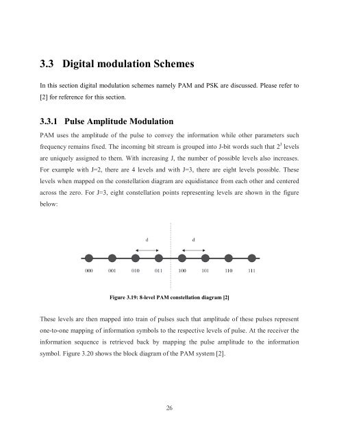
For example with J=2, there are 4 levels and with J=3, there are eight levels possible. These<br />
levels when mapped on the constellation diagram are equidistance from each other and centered<br />
across the zero. For J=3, eight constellation points representing levels are shown in the figure<br />
below:<br />
Figure 3.19: 8-level PAM constellation diagram [2]<br />
These levels are then mapped into train of pulses such that amplitude of these pulses represent<br />
one-to-one mapping of information symbols to the respective levels of pulse. At the receiver the<br />
information sequence is retrieved back by mapping the pulse amplitude to the information<br />
symbol. Figure 3.20 shows the block diagram of the PAM system [2].<br />
26