SIMPACK Code Export
SIMPACK Code Export
SIMPACK Code Export
- TAGS
- simpack
- export
- www.simpack.com

Create successful ePaper yourself
Turn your PDF publications into a flip-book with our unique Google optimized e-Paper software.
Editor<br />
INTEC GmbH, Argelsrieder Feld 13, D-82234 Wessling<br />
VOLUME 8, FIRST ISSUE<br />
<strong>SIMPACK</strong> <strong>Code</strong> <strong>Export</strong><br />
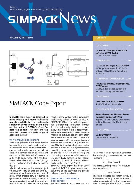
<strong>SIMPACK</strong> <strong>Code</strong> <strong>Export</strong> is designed to<br />
make existing and future multi-body<br />
models available to non multi-body<br />
simulation environments. Learn more<br />
on the basics of <strong>SIMPACK</strong> <strong>Code</strong> <strong>Export</strong>,<br />
the principle structure and the<br />
be ne fi ts it offers in a wide range of<br />
application areas.<br />
WHY <strong>SIMPACK</strong> CODE EXPORT<br />
How can general multi-body models<br />
be used in a non multi-body environment<br />
by non multi-body experts? How<br />
can a multi-body vehicle model be<br />
used in a control design environment<br />
such as MATLAB/Simulink? How can<br />
a 3D-multi-body model of a construction<br />
machine be used in a 1D-fl uid dynamics<br />
software for hydraulic system<br />
design?<br />
Multi-body models of trucks are subject<br />
to a huge variety of possible confi gurations<br />
such as the number and type of<br />
axles. What process fl ow is required to<br />
generate real-time models, which can<br />
be incorporated in a real-time environment?<br />
How can complex multi-body<br />
models along with a highly specialised<br />
multi-body solver be used outside of<br />
<strong>SIMPACK</strong>? What is a suitable process<br />
for transferring simulation models<br />
from a multi-body division in a company<br />
to a control design department?<br />
What is a suitable link from <strong>SIMPACK</strong><br />
models to in-house specifi c simulation<br />
environments? How can I close the<br />
gap between off-line simulation and<br />
on-line simulation? Is it possible for<br />
an OEM to transfer black-box vehicle<br />
dynamics models to a supplier without<br />
revealing structure and parameters<br />
of the car? How can engineering and<br />
consulting companies offer ready to<br />
use multi-body models to their clients<br />
without the need of running a multibody<br />
tool at the clients’ site?<br />
<strong>SIMPACK</strong> <strong>Code</strong> <strong>Export</strong> has been de veloped<br />
at INTEC to give answers and<br />
so lu tions to the technical and process<br />
relevant questions above.<br />
BASIC PRINCIPLE OF <strong>SIMPACK</strong><br />
CODE EXPORT<br />
<strong>SIMPACK</strong> <strong>Code</strong> <strong>Export</strong> takes an indi-<br />
JULY 2004<br />
» SOFTWARE ................................01<br />
Dr. Alex Eichberger, Frank Kohlschmied,<br />
INTEC GmbH<br />
<strong>SIMPACK</strong> <strong>Code</strong> <strong>Export</strong><br />
» INTEC GMBH..............................03<br />
Dr. Alex Eichberger, INTEC GmbH<br />
INTEC partners up with IST: EHD-<br />
Software TOWER now Available in<br />
<strong>SIMPACK</strong><br />
» UNIVERSITY APPLICATION........04<br />
Thomas Thümmel, Jospeh Woyke,<br />
TU München<br />
<strong>SIMPACK</strong> FEMBS Simulation of a<br />
Moulded Pantograph Mechanism<br />
» SOFTWARE ................................06<br />
Johannes Gerl, INTEC GmbH<br />
<strong>SIMPACK</strong> Virutal Suspension<br />
» CUSTOMER APPLICATION.........09<br />
Roger Gansekow, Siemens Transportation<br />
System, Krefeld<br />
Approval of the Siemens Desiro Series<br />
Vehicle Dynamics for Use in Great<br />
Britain<br />
» SOFTWARE ............................... 11<br />
Dr. Lutz Mauer<br />
Gearwheels in <strong>SIMPACK</strong><br />
vidual model as its input and generates<br />
the underlying parameterised motion<br />
equations<br />
,<br />
and corresponding sensor- or measurement<br />
equations<br />
,<br />
whereas x denotes the system states, u<br />
is the system input, y contains the sensor<br />
outputs and p stands for the free parameters<br />
of the exported simulation model.
» SOFTWARE<br />
Dr. Alex Eichberger, Frank Kohlschmied<br />
INTEC GmbH<br />
The motion equations can be generated<br />
as ordinary fi rst order differential<br />
equations or, depending on the model,<br />
in addition, as differential algebraic<br />
equations. The equations are currently<br />
exported in Fortran and, in the future,<br />
the option to export the code in standard<br />
C will also be available. This makes it<br />
possible to use the code, once exported,<br />
in any simulation environment.<br />
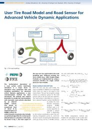
The structure of <strong>SIMPACK</strong> <strong>Code</strong> <strong>Export</strong><br />
is shown below. The license <strong>Code</strong> <strong>Export</strong><br />
enables the export of the model equations<br />
as source code; additional fi les are<br />
also generated for supplying the exported<br />
model with data and initial states.<br />
Independent from <strong>SIMPACK</strong>, the model<br />
can be compiled and linked with external<br />
code to build an executable program.<br />
At run-time, the model references a<br />
subset of the licensed (Execution) SIM-<br />
PACK libraries which are shipped with<br />
the module <strong>SIMPACK</strong> <strong>Code</strong> <strong>Export</strong>. The<br />
equations of motion are solved by the<br />
external solver in the simulation environment<br />
or, optionally, if a Time Domain<br />
Solver license is available, the exported<br />
<strong>SIMPACK</strong> solver can be used.<br />
The exported model and optional solver<br />
can now be used in any external simu-<br />
lation environment without requiring<br />
a <strong>SIMPACK</strong> installation. To generate<br />
a ready-to-use model for MATLAB/<br />
Simulink, the model can be exported<br />
as a S-function, with the option of including<br />
the <strong>SIMPACK</strong> solver. Model and<br />
solver can now be run in multiple calculation<br />
cases by control design engineers.<br />
The often confi dential model structure<br />
and topology are not transparent to the<br />
end user; only the data made available<br />
by the <strong>Code</strong> <strong>Export</strong> modeller for parameterisation<br />
in the code generation are<br />
visible and therefore can be altered.<br />
SCOPE OF FUNCTIONALITY<br />
Approximately 80% of the <strong>SIMPACK</strong><br />
elements can be currently used in the<br />
exported code, with the range being<br />
continually expanded. An up-to-date<br />
list of the functions ready to use within<br />
<strong>Code</strong> <strong>Export</strong> can be requested from our<br />
<strong>Code</strong> <strong>Export</strong> product manager Frank<br />
Kohlschmied (frank.kohlschmied@simp<br />
ack.de).<br />
APPLICATION AREAS<br />
<strong>SIMPACK</strong> <strong>Code</strong> <strong>Export</strong> has been designed<br />
to make existing and future<br />
multi-body models available to any<br />
2<br />
non <strong>SIMPACK</strong> simulation environment.<br />
Application areas are hardware-in-the<br />
loop, software-in-the loop, simulators<br />
and general real-time applications. It is<br />
also the tool designed for engineering<br />
and consulting companies who develop<br />
multi-body models for clients, who want<br />
to use those models independently from<br />
a <strong>SIMPACK</strong> installation. Finally, by means<br />
of <strong>SIMPACK</strong> <strong>Code</strong> export, multi-body<br />
models can be used as a „black box“ by<br />
third-parties, without having to reveal<br />
the model topology and structure.<br />
INTRODUCTORY DAY<br />
In summer this year, a one day free of<br />
charge introduction to <strong>SIMPACK</strong> <strong>Code</strong><br />
<strong>Export</strong> will be offered to those interested<br />
in learning more about <strong>SIMPACK</strong> <strong>Code</strong><br />
<strong>Export</strong>. If you are interested in attending<br />
the introduction course, don’t hesitate in<br />
contacting our Marketing Manager, Ms<br />
Ernie Engert (ernie.engert@simpack.de).<br />
More information avai lable on <strong>SIMPACK</strong><br />
<strong>Code</strong> <strong>Export</strong>, www.simpack.com.
INTEC partners up with IST:<br />
EHD-Software TOWER now<br />
Available in <strong>SIMPACK</strong><br />
Proposed by the Mercedes Formula 1<br />
engine division, IST GmbH and INTEC<br />
GmbH teamed up to develop a powerful<br />
interface for the precise simulation<br />
of hydro-dynamic effects in multibody<br />
applications. The impedance<br />
method and the Reynold approach<br />
of the IST software TOWER are now<br />
available within the new module<br />
<strong>SIMPACK</strong> Engine. INTEC GmbH, along<br />
with its local distributors, operates as<br />
a worldwide supplier for the TOWER<br />
software embedded into <strong>SIMPACK</strong>.<br />
IST GmbH is a consulting engineer<br />
company whose main focus is the<br />
numerical simulation of structural dynamics<br />
and the elasto-hydrodynamics<br />
of combustion engine components. IST<br />
develops software tools for the simulation<br />
and analysis of elasto-hydrodynamically<br />
coupled systems, such as:<br />
- piston - cylinder<br />
- piston pin - piston<br />
- piston pin - con-rod<br />
- crank shaft - engine block<br />
- crank pin - connecting rod<br />
- piston - piston rings - cylinder.<br />
IST has undertaken the task of maintenance<br />
and development of the<br />
software, as well as offering training<br />
in its use. The software is based upon<br />
research work carried out at the IMK,<br />
University of Kassel, under the direction<br />
of Professor Gunter Knoll.<br />
Besides software development and<br />
maintenance, IST offers a wide range<br />
of engineering services in the fi eld of<br />
hydrodynamic bearing calculation and<br />
structural analysis, with a focus on<br />
combustion engine components.<br />
<strong>SIMPACK</strong> now offers an integrated<br />
interface to the IST software TOWER,<br />
which is a software tool for the general<br />
elasto-hydrodynamic analysis of<br />
bearings. It is based on the hydrodynamic<br />
lubrication theory of rough<br />
surfaces, and uses different lubrication<br />
models, dependent upon tribological<br />
properties, fl ow factors and<br />
contact pressure. The interface markedly<br />
improves the results delivered by<br />
multi-body programs regarding the<br />
relevant frequency dependent spring<br />
3<br />
and damping characteristics of the<br />
lubrication fi lm, as well as the interaction<br />
between the deformations in<br />
the bearing and tribological relevant<br />
quantities, which include minimal gap,<br />
pressure distribution, centre point<br />
track and friction losses.<br />
The interface is offered at two different<br />
levels. The fi rst level, the so<br />
called impedance method, is a table<br />
based solution for the pre-design of<br />
bearings limited to rigid cylindrical<br />
bearing types. At the second level, the<br />
underlying Reynolds differential equations<br />
are directly solved by a fi nite<br />
element algorithm. This results in a<br />
more detailed model of the structural<br />
dynamics, including the tribological<br />
characteristics, allowing the bearing<br />
geometry and global bearing elasticity<br />
to be taken into account.<br />
The co-operation between IST and<br />
INTEC provides an EHD solution from<br />
one source for all <strong>SIMPACK</strong> users<br />
and interested parties. The solution<br />
comes as part of the <strong>SIMPACK</strong> Engine<br />
module; the functionality is, however,<br />
also available separately. The partnership,<br />
and with it the expansion into<br />
EHD analysis, further enhances our<br />
outstanding technical support, training<br />
and consulting service. For those<br />
customers who are looking to extend<br />
their simulation technology to the<br />
limits, the partnership gives them the<br />
opportunity to include detailed elastohydrodynamic<br />
modelling within their<br />
multi-body environment.<br />
More information<br />
www.ist-aachen.com<br />
www.simpack.com<br />
» SOFTWARE<br />
Dr. Alex Eichberger<br />
INTEC GmbH<br />
Deformed bearing showing the<br />
distribution of oil pressure<br />
Dr. Schönen, Director Software<br />
Development, iST GmbH
» UNIVERSITY APPLICATION<br />
Th. Thümmel, J. Woyke<br />
TU München<br />
Figure 1<br />
Figure 2<br />
Figure 3<br />
<strong>SIMPACK</strong>»News, July 2004<br />
4<br />
<strong>SIMPACK</strong> FEMBS Simulation of a<br />
Moulded Pantograph Mechanism<br />
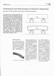
A miniature pantograph mechanism<br />
of uniform material, including largedefl<br />
ective hinges , has been designed<br />
to assemble portable electric devices,<br />
e.g. mobile telephones. High adaptability<br />
in its functionality and usage,<br />
as well as a high-speed of up to 20<br />
cycles per second are required. Positioning<br />
errors are to be expected due<br />
to the inertia forces, which cause the<br />
mechanism to deform elastically.<br />
The design of the mechanism has<br />
necessitated the use of an advanced<br />
tool in its virtual prototyping. With<br />
the help of the <strong>SIMPACK</strong> interface to<br />
FEA programs, FEMBS, selected eigenmodes,<br />
calculated in ANSYS, were imported<br />
into <strong>SIMPACK</strong>, where a surface<br />
mount job was successfully modelled.<br />
OBJECT OF INVESTIGATION<br />
Small, portable electrical and electronic<br />
devices and computer accessories<br />
contain minute devices of less than<br />
a few square-millimetres located on<br />
electric circuit boards. However, most<br />
of the mm-sized devices are often assembled<br />
by huge surface mounting<br />
systems in the dimension of a metre.<br />
A new surface mount system composed<br />
of parallel arranged miniature<br />
manipulators has been proposed. One<br />
miniature manipulator consists of a<br />
moulded two degree of freedom pantograph<br />
mechanism, which involves<br />
hinges, providing large defl ections, (A,<br />
B, C, D, and F) and links; both of these<br />
components are made of the same<br />
material, i.e. PP (Polypropylene), as<br />
shown in Figure 1.<br />
However this type of construction<br />
introduces new problems regarding<br />
positioning and vibrations due to nonlinear<br />
kinematics and dynamics, caused<br />
by large defl ections of the hinges,<br />
elastic bending of the links and varying<br />
inertia forces. Building a model,<br />
that includes the pantograph’s exact<br />
dynamics and kinematics, could create<br />
the ability to compensate positioning<br />
errors by input motion control.<br />
Figure 2 illustrates the dimensions and<br />
simplest rigid-body linkage model of<br />
the pantograph mechanism, with the<br />
motion of the system defi ned via the<br />
following global transfer functions<br />
x = - 4 s x<br />
y = 5 s y<br />
MODELLING THE PANTOGRAPH<br />
MECHANISM<br />
An enhanced model of the pantograph<br />
is built up in <strong>SIMPACK</strong> as shown<br />
in Figure 3. The hinges A to F are<br />
modelled as revolute joints combined<br />
with non-linear torsion spring-damper<br />
elements.<br />
A static FEM analysis calculated the<br />
non-linear spring properties using<br />
elastic ANSYS-models for the hinge.<br />
The non-linear stress-strain-curve for<br />
polypropylene provided the elastic<br />
material properties. By fi xing one side<br />
of the hinge and displacing the other,<br />
the reaction torques were be determined.<br />
The FEM calculation resulted<br />
in the non-linear torsion spring characteristics<br />
of the hinges, approximated<br />
as a polynomial of 5 th order.<br />
As a fi rst estimation an approximately<br />
constant damping characteristic was<br />
available from experiments performed<br />
at Tokyo Institute of Technology P&I<br />
Lab, in the Professor Horie Group. In<br />
these experiments thin beams including<br />
one hinge capable of large defl ections<br />
was given an initial deformation.<br />
The response function was then measured<br />
allowing the damping ration to<br />
be calculated.<br />
In order to get the modal parameters<br />
of the pantograph, a modal analysis<br />
with a maximum of 300 Hz was<br />
performed using ANSYS. Fixed drives<br />
were assumed as boundary conditions,<br />
which meant the linear actuators were<br />
not displaced.<br />
This delivered four eigenfrequencies<br />
and corresponding eigenforms, two in<br />
transverse, i.e. normal to the working<br />
plane, and two bending eigenforms.<br />
In the mechanism itself it is unlikely<br />
that there are excitations in the transverse<br />
direction, and therefore the two<br />
bending eigenforms at 94 Hz and 205<br />
Hz were investigated, see fi gure 4.<br />
The fi rst approach investigated the two<br />
beams (link 2 and link 5) in ANSYS with<br />
the boundary conditions matching the
eigenmodes of the pantograph parts.<br />
The results were then exported into<br />
<strong>SIMPACK</strong> via the interface FEMBS.<br />
An elastic multi-body system model<br />
shown in fi gure 3 was built, which<br />
delivered the eigen frequencies of 106<br />
and 239 Hz.<br />
VERIFICATION BY A SPECIAL<br />
MOTION TASK<br />
Figure 5 shows two chosen trajectories<br />
of the tool point E when surface<br />
mounted. Trajectory A is a very simple<br />
motion, where the mechanism is used<br />
to pick and place an object. Trajectory<br />
B is an advanced version of trajectory<br />
A, designed to reduce the dynamic<br />
displacement error of output point E.<br />
Trajectory B provides the required motion,<br />
but without the corners seen in<br />
the motion of trajectory A. Nevertheless,<br />
input functions s x and s y for both<br />
trajectories include sinusoidal connections<br />
in the time domain (no jumps in<br />
velocity and acceleration). The rigid<br />
linkage model, see fi gure 2, would<br />
deliver the reference without dynamic<br />
displacement error and vibrations.<br />
The frequencies of these jobs are both<br />
6.67 Hz i.e. the cycle is 150 ms. The input<br />
functions can be designed in many<br />
ways, however, the comparison trajectories<br />
A and B are suffi ciently simple<br />
to allow the dynamic characteristics of<br />
the deviations of the tool point E to be<br />
investigated.<br />
Figure 6 shows the dynamic displacement<br />
error of the output point E from<br />
the reference trajectory shown in Figure<br />
5.<br />
In the future, the elastic multi-body<br />
system will be verifi ed experimentally.<br />
An iterative improvement of the multibody<br />
system with FEM and experimental<br />
methods will also follow.<br />
The import of mode shapes of elastic<br />
bodies does increase the accuracy<br />
obtained when calculating a mechanism’s<br />
motion.<br />
5<br />
More information at<br />
Thomas Thümmel, Joseph Woyke<br />
Lehrstuhl für Angewandte Mechanik,<br />
Technische Universität München<br />
www.amm.mw.tum.de<br />
in cooperation with:<br />
Tokyo Institute of Technology<br />
P&I Lab, Prof. Horie Group<br />
» UNIVERSITY APPLICATION<br />
Th. Thümmel, J. Woyke<br />
TU München<br />
Figure 4<br />
Figure 5<br />
Figure 6
» SOFTWARE<br />
Johannes Gerl<br />
INTEC GmbH<br />
Virtual and standard suspension<br />
Integration has been performed<br />
from 0.0 sec to 8.0 sec. The indicated<br />
CPU times were output to<br />
MATLAB Simulink and include initialisation<br />
time and time for the<br />
measurement of the outputs from<br />
the states.<br />
Calculations have been performed<br />
on Intel Pentium III, 866MHz ,<br />
261.100 kb RAM.<br />
<strong>SIMPACK</strong> Virtual Suspension<br />
In order to improve vehicle performance<br />
in terms of handling, stability and ride<br />
comfort the usage of controlled systems<br />
has increased tremendously. This trend<br />
requires the availability of effi cient<br />
and easy-to-use, three dimensional<br />
vehicle models within control system<br />
simulation environments. By replacing<br />
the detailed kinematic structure of a<br />
multi-body suspension model with a<br />
simple look-up table based modelling<br />
approach, <strong>SIMPACK</strong> Virtual Suspension<br />
now offers an integrated process to<br />
reduce the model complexity essential<br />
for hardware- and software-in-the-loop<br />
simulations.<br />
REQUIREMENTS<br />
3D vehicle models that are used by<br />
control system experts do not have to<br />
fulfi l the same requirements as models<br />
used for the design of purely mechanical<br />
system parts. The purely mechanical<br />
systems need to allow insight into<br />
the effects that appear at each single<br />
bushing, whereby the control system<br />
modeller need only know the behaviour<br />
of the suspension as a whole, reducing<br />
the complexity of the required model.<br />
In addition, the co-operation between<br />
the vehicle manufacturer and the system<br />
supplier may restrict the release of confi<br />
dential suspension data.<br />
For the model to be used in a control<br />
system environment, it is necessary that<br />
equations do not contain differential<br />
algebraic equations (DAE), as the solvers<br />
in control environments often do not<br />
have the functionality to deal with DAEs,<br />
the case with MATLAB Simulink. One of<br />
the major features of the virtual suspension<br />
joint is that the suspension system<br />
does not require any DAEs.<br />
KINEMATICS STORED IN LOOK-UP<br />
TABLES<br />
The basic idea of <strong>SIMPACK</strong>’s virtual suspension<br />
joint is to read-in the position of<br />
a suspension system from look-up tables<br />
during an analysis, instead of evaluating<br />
the system’s kinematic behaviour during<br />
the calculation. The look-up tables are<br />
generated from a previous multi-body<br />
system analysis in which <strong>SIMPACK</strong> writes<br />
the suspension kinematics to the tables.<br />
<strong>SIMPACK</strong>»News, July 2004<br />
6<br />
When using the virtual suspension joint<br />
to connect the wheel carrier with the<br />
chassis body within automotive models,<br />
all the connecting bodies that represent<br />
the wishbones can be eliminated. The<br />
‘dependent’ degrees of freedom of the<br />
wheel carrier such as the toe and camber<br />
angle are therefore stored as a function<br />
of the wheel lift and, where applicable,<br />
of the steering state. <strong>SIMPACK</strong> automatically<br />
applies splining algorithms to<br />
evaluate the relevant function tables<br />
whilst the analysis is carried out. The<br />
equations of motion that are required<br />
to represent the suspension behaviour<br />
are reduced and, more importantly, the<br />
algebraic equations are avoided. The<br />
virtual suspension system modelled<br />
in <strong>SIMPACK</strong> is represented entirely by<br />
ODEs. Rear suspensions therefore are<br />
modelled with just one degree of freedom<br />
(wheel lift) and front suspensions<br />
with two degrees of freedom (wheel lift<br />
and steering angle).<br />
ADDITIONAL SUSPENSION ELEMENTS<br />
Due to the fact that e.g. wishbone<br />
bodies are removed when using the virtual<br />
suspension joint, any other element<br />
which was referenced to these bodies<br />
(like shock absorbers, stabiliser bar) must<br />
now be connected to the wheel carrier.<br />
This means that, for instance, the stiffness<br />
and damping characteristics of a<br />
suspension strut must be transformed<br />
according to the modifi ed connection<br />
points. The <strong>SIMPACK</strong> Virtual Suspension<br />
offers specialised elements for the suspension<br />
strut and the stabiliser bar that<br />
support the user in carrying out these<br />
transformations, avoiding too much manual<br />
calculation effort.<br />
Additionally, a steering element designed<br />
for the use with the virtual suspension<br />
joint is available which makes<br />
it easy to connect any external steering<br />
input, provided by MATLAB Simulink for<br />
example, to the suspension joint.<br />
ELASTO-KINEMATIC SUSPENSION JOINT<br />
When preparing a suspension for the<br />
elasto-kinematic virtual suspension<br />
joint, additionally to the kinematics,<br />
the movement of the wheel carrier as<br />
a reaction to certain forces or torques is
saved. By adding a certain elastic movement<br />
to the kinematic movement of the<br />
suspension, the virtual suspension joint<br />
can then also take into consideration<br />
the elasto-kinematic behaviour of the<br />
suspension. The force/torque dependency<br />
on the wheel carrier movement can<br />
be both a linear or non-linear function.<br />
CREATION OF LOOK-UP TABLES<br />
In order to create the look-up tables<br />
required by the virtual suspension joint,<br />
an analysis with the <strong>SIMPACK</strong> module<br />
Virtual Testing Lab is carried out. By successive<br />
time domain or static equilibrium<br />
simulation of the complex suspension<br />
model, together with an appropriate<br />
test bench template and plot fi lter, the<br />
look-up tables can easily be created. Alternatively,<br />
the virtual suspension data<br />
format from MSC.ADAMS (scf-fi les) is<br />
supported.<br />
The look-up tables can also be provided<br />
from measurement data. For the virtual<br />
suspension joint, <strong>SIMPACK</strong> relies on the<br />
function array set data format which is<br />
a standard modelling element within<br />
<strong>SIMPACK</strong> and is in ASCII-format.<br />
CALCULATION PERFORMANCE<br />
Due to the signifi cant reduction in the<br />
degrees of freedom, vehicle models that<br />
are based on the virtual suspension joint<br />
show extremely high calculation performance.<br />
The table shows a comparison<br />
between a fully detailed <strong>SIMPACK</strong><br />
model and the same model, but using<br />
look-up table joints. Kinematic and elasto-kinematic<br />
variants were simulated for<br />
a double lane change and transition of<br />
a road bump. Due to the elimination of<br />
algebraic equations (and therefore an<br />
ODE representation instead of DAE), a<br />
simple explicit Euler time integrator can<br />
be used for the model with virtual suspension<br />
joints. The simulation performance<br />
on a Pentium III (specifi cation see<br />
below) with the Euler integrator clearly<br />
demonstrates that these kinds of models<br />
are suited for real-time simulation.<br />
The models are available for download<br />
from www.simpack.com, service/support,<br />
model database. They require <strong>SIMPACK</strong><br />
Version 8618 or higher. Please contact<br />
your local <strong>SIMPACK</strong> distributor to re-<br />
7 » SOFTWARE<br />
ceive a trial version. A tutorial about<br />
how to use the virtual suspension joint<br />
is also available.<br />
COMPATIBILITY AND AREAS OF APPLI-<br />
CATION<br />
All of the modelling elements that are<br />
delivered with the new package SIM-<br />
PACK Virtual Suspension are fully compatible<br />
with all other <strong>SIMPACK</strong> modules,<br />
including <strong>SIMPACK</strong> <strong>Code</strong> <strong>Export</strong>. The<br />
virtual suspension joint, as well as the<br />
virtual steering, virtual stabiliser bar and<br />
virtual suspension strut elements can be<br />
stored in <strong>SIMPACK</strong> databases. It is therefore<br />
possible to use one main model<br />
with combinations of the complex multibody<br />
suspension model or alternatively<br />
with the virtual suspensions, read-in as<br />
substructures.<br />
As mentioned in the article <strong>SIMPACK</strong><br />
<strong>Code</strong> <strong>Export</strong> by Dr. Alex Eichberger in<br />
this edition of <strong>SIMPACK</strong> News, the compatibility<br />
with <strong>SIMPACK</strong> <strong>Code</strong> <strong>Export</strong>s<br />
allows the user to create <strong>SIMPACK</strong> models<br />
that are perfectly suited for SIL and,<br />
for the case that certain requirements<br />
regarding the creation of code are fulfi<br />
lled, also HIL simulation. These models<br />
can be exported to MATLAB Simulink<br />
and other control simulation tools very<br />
effi ciently, both from a technical and a<br />
cost point of view. Therefore, for the<br />
fi rst time, a tool is available that offers<br />
an integrated process to create multibody<br />
models for both mechanical design<br />
purposes of suspensions and the design<br />
of control systems.<br />
In spite of the fact that the design of<br />
<strong>SIMPACK</strong> Virtual Suspension was driven<br />
mainly by automotive application fi elds,<br />
the approach is not at all limited to<br />
automotive models. Users from other areas<br />
like railway engineering can benefi t<br />
from its features, too, for the look-up<br />
table joint can be used as a standard<br />
<strong>SIMPACK</strong> joint between arbitrary bodies.<br />
FURTHER STEPS<br />
INTEC is working on the implementation<br />
of optimised bumper elements to be<br />
used along with the Virtual Suspension<br />
increasing the performance, particularly<br />
for real-time simulations.<br />
Johannes Gerl<br />
INTEC GmbH<br />
If you are interested in taking<br />
part in our free-of-charge introduction<br />
day to <strong>SIMPACK</strong> Virtual<br />
Suspension, please contact Ms.<br />
Ernie Engert via telephone 0049<br />
8153 9288-40 or send an e-mail to<br />
ernie.engert@simpack.de.
» CUSTOMER APPLICATION<br />
Roger Gansekow<br />
Siemens Transportation Systems, Krefeld<br />
Desiro UK for South West Trains<br />
Simulation model of Desiro UK-<br />
eigenmode from ANSYS is scaled<br />
up<br />
<strong>SIMPACK</strong>»News, July 2004<br />
8<br />
Approval of the Siemens<br />
Desiro Series Vehicle Dynamics<br />
for Use in Great Britain<br />
The approval of railway vehicles requires<br />
extensive verifi cation, both<br />
theoretical and practical testing.<br />
The Siemens Desiro series has been<br />
approved according to the British<br />
regulations. The approval of the vehicle<br />
dynamics was achieved through<br />
theoretical testing, with the help of<br />
multi-body simulation, and practically,<br />
through applied static and dynamic<br />
testing. The close co-operation of the<br />
calculation and test divisions is essential<br />
for the use of the test results for<br />
further analyses.<br />
APPROVAL OF SIEMENS DESIRO<br />
Different versions of the Siemens Desiro<br />
Family have been developed for<br />
regional service in Great Britain. The<br />
Desiro UK is an electrical multiple<br />
unit (EMU) operating at speeds up to<br />
160km/h in direct and alternating current<br />
networks. Siemens was contractually<br />
required deliver approved trains.<br />
In Great Britain a „Safety case“ has to<br />
be produced prior to a new train coming<br />
into service. The safety case must<br />
demonstrate that, during the design<br />
and manufacture of the train, the<br />
customer requisites and the standards<br />
and laws in force are observed and the<br />
best available technology has been<br />
used. The safety case must prove the<br />
requirements of the Rail Group Standards<br />
(RGS) are complied with, with the<br />
verifi cation provided by theoretical<br />
and practical testing. Results provided<br />
from calculations performed with validated<br />
calculation models are accepted<br />
for the approval of the vehicle.<br />
REQUIREMENTS FOR THE VEHICLE<br />
DYNAMICS<br />
The following points are defi ned by<br />
the RGS as criteria for the approval to<br />
international standards:<br />
− resistance against derailment<br />
− wheel/rail-force<br />
− bogie stability<br />
− gauging<br />
− pantograph sway<br />
A catalogue of calculations and tests<br />
is then created, from these criteria, to<br />
be used for the vehicles compliance<br />
analysis. Desiro UK has been subjected<br />
to the following investigations:<br />
− wheel unloading on twisted track<br />
(calculation and test)<br />
− bogie rotational resistance (calculation<br />
and test)<br />
− wheel/rail-forces (calculation)<br />
− bogie stability (calculation and test)<br />
− running safety and ride comfort on<br />
track (calculation and test)<br />
− sway test (calculation and test).<br />
<strong>SIMPACK</strong> SIMULATION MODEL<br />
At Siemens TS TR calculations of the<br />
vehicle dynamics are performed with<br />
<strong>SIMPACK</strong>. The Desiro UK is modelled<br />
as multi body system with concentrated<br />
masses, stiffnesses and damping.<br />
Wheelsets and bogie frame are stiff<br />
bodies, while the car body is elastic<br />
with additional structural degrees<br />
of freedom up to 40 Hz; the body is<br />
imported from ANSYS via the FEMBS<br />
interface.<br />
Springs, dampers and bumpstops have<br />
linear or non-linear characteristics.<br />
Dependent upon the calculation, linear<br />
or non-linear contact mechanics<br />
including theoretical wheel and rail<br />
profi les, are used. The track model<br />
has dynamic masses, stiffnesses and<br />
damping.<br />
This model is used for the calculation<br />
of eigenmodes, static equilibrium, linear<br />
and non-linear stability analyses<br />
and non-linear time integration. The<br />
specifi c operating conditions relating<br />
to track irregularities and wheel/rail<br />
profi les or conicity are also considered.<br />
The results generated included the<br />
coupling of eigenmodes, compliance<br />
with stability requirements, wheel/<br />
rail-forces, suspension travel and accelerations<br />
of components and of the<br />
car body.<br />
SWAY CALCULATION FOR GAUGING<br />
PURPOSES<br />
A particularly demanding criterion<br />
in Great Britain is the compliance<br />
with the vehicle gauge. As the clearances<br />
along the track are very tight<br />
every millimetre counts. The goal is<br />
to achieve the largest vehicle possible<br />
with the smallest gap between the
vehicle and platform. The compliance<br />
with standard gauges in most cases<br />
does not provide the required space<br />
for the passengers. Therefore realistic<br />
movements of the vehicle have to be<br />
determined by calculation. These consist<br />
of quasi-static and dynamic sway<br />
movements and vertical suspension<br />
travel.<br />
The sway is calculated by a dedicated<br />
sway model. Since the required cant<br />
values and subsequently the suspension<br />
travel is quite large, particularly<br />
in the secondary springs (air springs),<br />
these need to be modelled in detail.<br />
The offset of the coupling points in<br />
the force element result in additional<br />
torques (r x F – terms). By means of<br />
a weighting factor the torque is distributed<br />
between the two coupling<br />
points. It has to be pointed out that<br />
due to this approach, the applied and<br />
opposing forces and torques are not<br />
necessarily the same at the two coupling<br />
points. This modelling requires<br />
specialised force elements.<br />
VERIFICATION OF THE SWAY CALCU-<br />
LATION<br />
The results of the calculations alone<br />
cannot be accepted for the vehicles’<br />
approval. Because testing of all vehicle<br />
types and load cases would be imprac-<br />
9 » CUSTOMER APPLICATION<br />
tical, a close interaction between calculation<br />
and tests is applied. The most<br />
critical vehicle types and load cases, according<br />
to the calculation results, are<br />
selected for the tests. In a special test<br />
rig, the basis (the track) is canted by<br />
defi ned cant values. The movements<br />
of the vehicle are measured by optical<br />
means; the identifi ed movements are<br />
then compared with the calculation<br />
predictions. By virtue of the good correlation<br />
of the sway test results, the<br />
extensive calculations, which were carried<br />
out, could be used for the verifi cation<br />
of vehicle gauging.<br />
CONCLUSION<br />
The vehicles of the Desiro UK family<br />
have been approved in Great Britain<br />
from the calculations and tests performed.<br />
The compliance with the criteria<br />
for derailment safety, wheel/rail<br />
forces, bogie stability, gauging and<br />
pantograph sway has been verifi ed. In<br />
addition the predictions from the simulations<br />
performed were confi rmed<br />
by tests that were carried out. After<br />
the completion of the tests in Great<br />
Britain, no further optimisation of the<br />
vehicles was necessary.<br />
Sway model Spring modelling: distribution of<br />
the torques on the two coupling<br />
points<br />
Roger Gansekow<br />
Siemens Transportation Systems, Krefeld<br />
Sway Test in the Validation Center<br />
Wildenrath<br />
Comparison of calculation and test<br />
results
» SOFTWARE<br />
Dr. Lutz Mauer<br />
INTEC GmbH<br />
GUI for the defi nition of the geometrical<br />
gearwheel parameters<br />
Helical gearwheels<br />
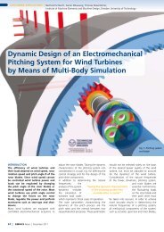
Gearwheels have now become an<br />
integral part of modern internal combustion<br />
engines and gearboxes, and<br />
therefore the ability to incorporate<br />
them into a multi-body system has become<br />
essential for the simulation engineer.<br />
The module <strong>SIMPACK</strong> Engine<br />
offers a Force Element to accurately<br />
simulate Gearwheel pairs by considering<br />
the forces and moments generated<br />
in meshing gears; the resulting overall<br />
transfer stiffness is calculated by adding<br />
the individual stiffness at each<br />
contacting tooth. The Force Element<br />
models involute gear geometry and<br />
consider the effect of multi-tooth contact,<br />
as well as backlash and changes<br />
in direction of the gear rotation.<br />
This new Force Element was designed<br />
to be easily confi gurable whilst offering<br />
a high level of technical performance,<br />
incorporating the characteristics<br />
inherent in the modelling of gears.<br />
Along with the contact mechanics<br />
within the meshing gears, the effects<br />
of changes to the relative position of<br />
the gear axes are an important feature<br />
within this element. The Gearwheel<br />
can be used to model spur tooth and<br />
helical involute gearing for multitooth<br />
contact, and to include the<br />
effects of backlash and gear rotation<br />
direction changes.<br />
GRAPHICAL PRIMITIVES<br />
The Gearwheel geometry is created<br />
from the respective graphical Primitive<br />
and is defi ned via the standard Gearwheel<br />
parameters; number of teeth,<br />
normal module, pressure angle, helix<br />
angle, addendum and dedendum<br />
coeffi cients, along with addendum<br />
modifi cation coeffi cient and backlash.<br />
The amount of detail shown in the<br />
visualisation of the Gearwheels can<br />
be modifi ed by defi ning the number<br />
of points used to describe the tooth<br />
fl ank, tip and root. However, changes<br />
to the graphical representation do not<br />
affect the accuracy of the force calculation.<br />
INPUT PARAMETERS<br />
The Gearwheel Force Element uses<br />
10<br />
Gearwheels in <strong>SIMPACK</strong><br />
<strong>SIMPACK</strong>»News, July 2004<br />
various different parameters to describe<br />
the geometrical relationship of<br />
the wheels to each other, as well as the<br />
physical and material properties of the<br />
Gearwheels. The parameters describing<br />
the geometrical form include:<br />
- A reference angle for the tooth position.<br />
- The face width of the meshing teeth.<br />
The parameters describing the physical<br />
and material properties include:<br />
- The mean Young’s modulus of both<br />
wheels.<br />
- The gearwheel form factor. This is<br />
used for the calculation of the weakening<br />
of the tooth, when compared<br />
to a gearwheel of complete crosssection.<br />
- The normal damping coeffi cient of<br />
meshing.<br />
- The coeffi cient of friction used for<br />
the calculation of the tangential<br />
forces induced from the meshing<br />
gears.<br />
- The parabolic function used to<br />
describe the normal stiffness, from<br />
the minimum to the maximum value,<br />
as the contact point progresses over<br />
the tooth.<br />
The parameter tip relief is used to<br />
smooth the running of the Gearwheels.<br />
The tip relief reduces the large<br />
changes in normal stiffness, which can<br />
occur for multi-tooth contact when<br />
gear teeth pairs commence and cease<br />
meshing.<br />
INPUT VARIABLES<br />
The Gearwheel Force Element is connected<br />
to two Body Fixed Markers,<br />
which are located on the rotational<br />
axis of the Gearwheels, and should<br />
be located at the centre point of the<br />
Gearwheel’s width. The parameters<br />
automatically provided by <strong>SIMPACK</strong><br />
are as follows:<br />
- The angle of the reference Marker<br />
of both gear Bodies.<br />
- The angular velocity of both gear<br />
Bodies.
- The relative axial displacement of<br />
the gear Bodies to each other.<br />
- The relative radial displacement of<br />
the Body Fixed Reference Frames.<br />
Due to radial or axial displacement of<br />
the wheels, it is possible for the wheels<br />
to come out of meshing. If the nominal<br />
tooth backlash reduces, due to a<br />
reduction in the axial displacement, it<br />
is possible for both tooth fl anks of the<br />
meshing teeth to come into contact.<br />
As an initial condition, the Gearwheel<br />
axes should be parallel. If the gear angle<br />
for all gear pairs are set to zero in<br />
the initial position, the simulation will<br />
begin without forces applied as the<br />
gear pairs are located in the centre of<br />
the backlash position.<br />
The force law for the calculation of the<br />
nominal force is calculated linearly or<br />
non-linearly as a function of the penetration<br />
of the involute tooth profi le.<br />
The tangential force, during meshing,<br />
is calculated from a Coulombic force<br />
law, with the friction coeffi cient given<br />
by the user.<br />
For the calculation of the resulting<br />
meshing stiffness, the contact ratio of<br />
the involute gearing is considered. The<br />
contact ratio is dependent on the current<br />
Gearwheel axial displacement. Up<br />
to fi ve tooth pairs can be in contact at<br />
any one time.<br />
OUTPUT VALUES<br />
The output values for the External<br />
Gear Force Element are the effective<br />
forces and moments applied at each<br />
wheel. The force and moments can<br />
also be output in Reference Frames,<br />
which do not rotate with the Gearwheels.<br />
In addition to other internal<br />
measurements which include Gearwheel<br />
angle, stiffness, force and position,<br />
it is possible to return the current<br />
meshing condition concerning the<br />
type of fl ank contact.<br />
PARTICULAR FEATURES OF THE FORCE<br />
ELEMENT<br />
The analytical calculation of the<br />
Gearwheel contact geometry reduces<br />
the need to search for the individual<br />
contact points, and therefore leads to<br />
11<br />
very effi cient calculation performance.<br />
At the start of the time integration,<br />
the meshing tooth pairs are all located<br />
at the centre of the tooth backlash<br />
position, ensuring no transient effects<br />
are present. The separate input<br />
of the initial tooth angle allows, for<br />
each Gearwheel level, the required<br />
meshing. For chains of Gearwheels,<br />
the phase relationship of the dependent<br />
Gearwheels is calculated from the<br />
initial tooth angle input of one of the<br />
Gearwheels. The tooth force pulsation,<br />
resulting from multi-tooth contact<br />
and the tooth stiffness function, can<br />
be reset to zero from two Force parameters.<br />
FUTURE DEVELOPMENTS<br />
An important aspect considered when<br />
the Gearwheel Force Element was<br />
implemented was to easily allow the<br />
future realisation of new features.<br />
Further planned developments to the<br />
Gearwheel are as follows:<br />
- Internal Gearwheel functionality.<br />
- Implementation of straight and helical<br />
bevel gears.<br />
- Calculation of the nominal tooth<br />
stiffness, dependent upon the<br />
number of teeth, the x-gear pair<br />
shift factors and the shape factor.<br />
- Implementation of non axially<br />
aligned gears, for use on fl exible<br />
shafts.<br />
SUMMARY<br />
The <strong>SIMPACK</strong> Gearwheel is an easily<br />
confi gurable Force Element, and<br />
allows the data to be entered easily<br />
and effi ciently. The calculation of the<br />
tooth forces considers all of the geometric<br />
features of the involute tooth.<br />
The optimised calculation algorithm<br />
used for the tooth forces means a<br />
simulation containing gearboxes<br />
with a large number of gears can be<br />
performed, whereby the phase difference<br />
of the meshing tooth pairs is<br />
accurately modelled.<br />
» SOFTWARE<br />
Dr. Lutz Mauer<br />
INTEC GmbH<br />
Spur gearwheels<br />
Automatically created primitive for<br />
Gear element
» NEWS<br />
<strong>SIMPACK</strong> Chain module<br />
Gunter Schupp with Prof. Arnold in<br />
the background<br />
LATEST NEWS<br />
NEW <strong>SIMPACK</strong> FEATURE MARKER<br />
RELATIVE TO MARKER<br />
<strong>SIMPACK</strong> Version 8614 introduced the<br />
feature, which allowed the position<br />
and orientation of one marker to be<br />
defi ned relative to another marker.<br />
The relationship between the two<br />
markers can be defi ned by simply<br />
selecting, in the ‘MBS Defi ne Marker’<br />
window, one marker (B) as the reference<br />
marker for another marker (A).<br />
The fi nal position of the marker A relative<br />
to its Body Fixed Reference Frame<br />
(BFRF) is calculated in a pre-processing<br />
step and does not change during the<br />
simulation. When the fi nal position<br />
and orientation of marker A on a body<br />
is calculated, fi rst the position and<br />
orientation of the reference marker<br />
B relative to its BFRF is calculated;<br />
this transformation is then applied to<br />
marker A in addition to the relative<br />
transformation of marker A that was<br />
entered by the user. The user entered<br />
relative transformation, i.e. Built-in Position<br />
and Orientation, is given in the<br />
co-ordinates of the reference marker B,<br />
whereby the two markers can belong<br />
to different bodies. The orientation<br />
and position of marker A can be fully<br />
parameterised. This feature is only<br />
available for Body Fixed Markers.<br />
NEW <strong>SIMPACK</strong> FEATURE: CENTRE OF<br />
MASS RELATIVE TO MARKER<br />
Since <strong>SIMPACK</strong> Version 8614 the centre<br />
of mass of a body can be defi ned at<br />
the position of, or relative to another<br />
marker. The marker that is referenced<br />
for the centre of mass must be a Body<br />
Fixed Marker and must be on the body<br />
to which the centre of mass is defi ned.<br />
NEW HOW-TO-MODEL <strong>SIMPACK</strong><br />
WHEEL/RAIL AT WWW.<strong>SIMPACK</strong>.COM<br />
A new How-To-Model guide is available<br />
from the <strong>SIMPACK</strong> website. The<br />
guide describes how to model and<br />
simulate a quasi-static curving analysis<br />
in <strong>SIMPACK</strong> Wheel/Rail for both standard<br />
and Virtual Testing Lab analyses.<br />
In addition, a How-To-Model guide<br />
for the calculation of Nominal Forces<br />
for Wheel/Rail models is also in the<br />
pipeline; the guide explains the math-<br />
<strong>SIMPACK</strong>»News, July 2004<br />
12<br />
ematical fundamentals and goes into<br />
detail about the modelling approaches<br />
and possible sources of error.<br />
<strong>SIMPACK</strong> CHAIN MODULE<br />
As a development within <strong>SIMPACK</strong><br />
Engine, INTEC is currently implementing<br />
a new chain mechanism simulation<br />
module. The prototype of this software<br />
has demonstrated extraordinary<br />
calculation performance and stability,<br />
benefi ting strongly from <strong>SIMPACK</strong>‘s<br />
relative co-ordinate recursive algorithm.<br />
An automatic chain model<br />
editor has been implemented to allow<br />
the effi cient creation of chain models<br />
based on geometric inputs from the<br />
user. The release date for the chain<br />
module is late summer 04.<br />
INTEC CONGRATULATES GUNTER<br />
SCHUPP ON COMPLETING HIS<br />
DOCTORAL EXAMINATION<br />
On the 12 th of March this year Gunter<br />
Schupp celebrated his doctoral ceremony<br />
at the institute B for Mechanics<br />
at the Technical University Stuttgart. A<br />
large contingent from his department<br />
at the DLR, as well as the MBS hardcore<br />
from INTEC travelled to Stuttgart<br />
for his doctoral presentation, to give<br />
Gunter their support. The topic was<br />
spot on for the limit cycle enthusiasts<br />
from the Wheel/Rail fi eld:<br />
“Numerical bifurcation analysis of nonlinear<br />
mechanical systems for use with<br />
railway vehicles.”<br />
For the long standing <strong>SIMPACK</strong> developer<br />
Gunter Schupp, it goes without<br />
saying that the Hopf and saddle graphs<br />
presented were from calculations performed<br />
within <strong>SIMPACK</strong>, whereby, for<br />
the analyses, the software PATH was<br />
coupled with <strong>SIMPACK</strong>. The examiners<br />
Professor Eberhart, Arnold and Schiehlen,<br />
after a worrying wait for Gunter,<br />
announced that he had passed with<br />
fl ying colours. As you can imagine, not<br />
only Professor True was overjoyed....
Hello,<br />
my name is Mario Baumann. In<br />
January 2001 I joined the <strong>SIMPACK</strong><br />
development team. While studying<br />
Mathematics at the FH (University of<br />
Applied Sciences) Regensburg, I was<br />
introduced to MBS simulation. I then<br />
went on to use the MBS tool <strong>SIMPACK</strong><br />
for my diploma thesis „optimisation<br />
algorithm for parameter identifi cation<br />
in a MBS fi eld“ at the Institute<br />
of Aeroelasticity, DLR Research Centre<br />
Oberpfaffenhofen. My programming<br />
tasks include:<br />
- Parameterisation (substitution variables,<br />
expressions)<br />
- Contact functionality (geometric contact,<br />
fl exible moved marker)<br />
- Virtual Testing Module<br />
- Inter Process Communication (cosim,<br />
simat)<br />
- LinuX port<br />
I spend my free time with my girlfriend<br />
Adele and playing table-tennis<br />
in my hometown of Boebrach.<br />
Hi there,<br />
my name is Gerhard Hippmann and I<br />
was born in 1968. After growing up in<br />
the charming Allgaeu region in Bavaria,<br />
I studied mechanical engineering<br />
at the Technical University of Munich.<br />
I gained my fi rst practical experience<br />
as a project engineer at Intec in 1997.<br />
One and a half years later I decided to<br />
move to the Vehicle System Dynamics<br />
Group of the German Aerospace<br />
Centre DLR to study for my doctorate<br />
in the fi eld of contact mechanics. In<br />
June 2003 I returned to Intec and am<br />
now working on the development and<br />
implementation of MBS methods. Visit<br />
my homepage www.hippie.org to fi nd<br />
out more about my private interests.<br />
13 » STAFF<br />
Hello,<br />
my name is Gerry Hofmann. I work<br />
on projects and support in Intec’s automotive<br />
department. After working<br />
for Intec as a freelancer for a couple of<br />
months, I fi nally joined the company<br />
in September 2003.<br />
I discovered my interest in simulating<br />
reality during my studies of „Mikro-<br />
und Feinwerktechnik“ (Mechatronics)<br />
at the Munich FH (University of Applied<br />
Sciences), and so consequently<br />
chose multi-body simulation for my diploma<br />
thesis and later in my work. My<br />
strong personal interest in automotive<br />
technology fi ts in perfectly with my<br />
day-to-day work.<br />
I spend a lot of my free time with classic<br />
black/white photography and as a<br />
drummer in a rock band.<br />
Mario Baumann<br />
Gerhard Hippmann<br />
Gerhard Hofmann
» MARKET REVIEW<br />
Johannes Gerl<br />
INTEC GmbH<br />
Johannes Gerl, Director Sales and<br />
Marketing<br />
MARKET REVIEW<br />
The current development of controlled<br />
vehicle dynamics systems,<br />
even for the high-end user, is to<br />
use different models, created in different<br />
programs, for each of the<br />
separate modelling tasks. Why is that?<br />
A suspension system incorporates a diverse<br />
band of relevant vibration effects,<br />
which cover a wide frequency range.<br />
Due to calculation performance and<br />
also the degree of specialisation of the<br />
engineers involved, it is not possible to<br />
use a single model for a NVH analysis,<br />
with a frequency content of 100 Hz or<br />
more, in a SIL project where (for instance<br />
in MATLAB Simulink) only handling<br />
dynamics are required. This model<br />
would also not be appropriate in a HIL<br />
<strong>SIMPACK</strong>»News, July 2004<br />
14<br />
analysis that must run in real-time.<br />
However with <strong>SIMPACK</strong>, it is possible<br />
to create the models in the same program,<br />
whereby the HIL and SIL simulation<br />
models can be created as a simplifi<br />
ed version of the complex multi-body<br />
models, and thereby meeting the<br />
specifi ed demands of the respective<br />
simulation environments. With the<br />
new product <strong>SIMPACK</strong> Virtual Suspension,<br />
the user can create look-up table<br />
joints that enable a simplifi ed and<br />
high performance representation of<br />
more complex models, which can then<br />
be exported to Simulink, via <strong>SIMPACK</strong><br />
<strong>Code</strong> <strong>Export</strong>, and thereby reducing<br />
the overall licensing costs.<br />
NEW UNIVERSITY AND RESEARCH LICENCES SINCE JANUARY 2004<br />
FH Rosenheim, Germany<br />
FH Heilbronn, Germany<br />
Fraunhofer Gesellschaft, Institut für Techno- und Wirtschaftsmathematik,<br />
Kaiserslautern, Germany<br />
Fraunhofer Institut für Betriebsfestigkeit, Darmstadt, Germany<br />
Nanjing University of Aeronautics and Astronautics (NUAA), P.R. China<br />
Neimenggu Technical University, Transportation Dept., China<br />
PLA University, Transportation Dept., Tianjin P.R. China<br />
TU Berlin, Institut für Land- und Seeverkehr, Germany<br />
TU Berlin, Institut für Konstruktion, Mikro- und Medizintechnik, Germany<br />
TU Graz, Austria<br />
TU Hanoi, Vietnam<br />
Universität Hohenheim, Institut für Agrartechnik, Hohenheim, Germany<br />
Uni Siegen, Germany<br />
NEW COMMERCIAL LICENCES SINCE JANUARY 2004<br />
AEA Technology Rail BV, Utrecht, The Netherlands<br />
AMST Systemtechnik Ges.m.b.H., Austria<br />
Baotou First Mechanism Works, P.R. China<br />
Das Kompetenzzentrum - Das Virtuelle Fahrzeug Forschungsges. mbH, Graz, Austria<br />
DaimlerChrysler Research, Stuttgart, Germany<br />
Mercedes Motorsport, Stuttgart, Germany<br />
MeSH Engineering, Dettenhausen, Germany<br />
R. Bosch GmbH, Stuttgart, Germany<br />
Voith Turbo, Crailsheim, Germany
<strong>SIMPACK</strong> TRAINING COURSES<br />
July 2004 12.07. – 13.07.2004 <strong>SIMPACK</strong> BASIC Training<br />
15<br />
14.07. - 15.07.2004 <strong>SIMPACK</strong> Wheel/Rail Training<br />
September 2004 13.09. – 14.09.2004 <strong>SIMPACK</strong> BASIC Training<br />
15.09. – 16.09.2004 <strong>SIMPACK</strong> Wheel/Rail Training<br />
15.09. – 15.09.2004 <strong>SIMPACK</strong> Automotive +<br />
17.09. – 17.09.2004 <strong>SIMPACK</strong> Contact Mechanics Training<br />
October 2004 11.10. – 12.10.2004 <strong>SIMPACK</strong> BASIC Training<br />
13.10. – 14.10.2004 <strong>SIMPACK</strong> FEMBS Training<br />
15.10. – 15.10.2004 SIMULINK Interface Training<br />
November 2004 15.11. – 16.11.2004 <strong>SIMPACK</strong> BASIC Training<br />
<strong>SIMPACK</strong> ACADEMY<br />
17.11. – 18.11.2004 <strong>SIMPACK</strong> Wheel/Rail Training<br />
17.11. – 17.11.2004 <strong>SIMPACK</strong> Automotive +<br />
05.10. - 08.10.2004 <strong>SIMPACK</strong> Academy: Low / High Frequency Tire Models<br />
27.01. - 28.01.2005 <strong>SIMPACK</strong> Academy: FE-MBS-Interfacing<br />
<strong>SIMPACK</strong> AT CONFERENCES AND EXHIBITIONS<br />
23.08. - 27.08.2004 AVEC 04, Arnhem, The Netherlands<br />
30.08. - 31.08.2004 3rd International Colloquium on „Tyre Models for Vehicle<br />
Dynamics Analysis“, TU Wien<br />
29.09. - 30.09.2004 VDI-Tagung Berechnung und Simulation im Fahrzeugbau,<br />
Würzburg<br />
04.10. - 06.10.2004 Aachen Colloquium, Automobile and Engine Technology,<br />
Aachen<br />
27.10. - 28.10.2004 NAFEMS Seminar: Analysis of Multi-Body Systems Using<br />
FEM and MBS<br />
09.11. - 10.11.2004 <strong>SIMPACK</strong> User Meeting<br />
at the Wartburg in Eisenach<br />
» TRAININGS AND CONFERENCES<br />
We would be glad to welcome you<br />
to our <strong>SIMPACK</strong> training courses<br />
or to a <strong>SIMPACK</strong> Academy course.<br />
To register for one of this courses<br />
or to discuss your training requirements<br />
please contact<br />
Ernie Sabine Engert by e-mail:<br />
ernie.engert@<strong>SIMPACK</strong>.de<br />
or by telephone:<br />
0049 8153 9288-40<br />
or by fax:<br />
0049 8153 9288-11<br />
Ms Engert looks forward to hearing<br />
from you.<br />
The Wartburg is where the <strong>SIMPACK</strong><br />
User Meeting 2004 will be held, on<br />
the 09th and 10th November
CONTACT<br />
» CHINA<br />
ESP<br />
Intelli-Center B Room 1709<br />
Zhongguancun East Road No.18<br />
Haidian District, Beijing 100080<br />
P.R. China<br />
Tel.: +86 - 10 - 826 015 56<br />
www.bj-esp.com<br />
» KOREA<br />
ADVANCED TECHNOLOGY ENGINEER-<br />
ING SERVICE LTD (ATES)<br />
8F Fine Bldg., 673-5 Deungchon-Dong,<br />
Kangseo-Gu, Seoul, KOREA<br />
Tel.: +82 - 2 - 2657 - 3544<br />
www.ates.co.kr<br />
PLEASE SIGN ME UP FOR THE FREE DELIVERY OF THE <strong>SIMPACK</strong>»NEWS<br />
(copy, fi ll in, fax to +49-8153-9288-11)<br />
Name<br />
First Name<br />
Firm<br />
Street<br />
Zip <strong>Code</strong><br />
Location<br />
Country<br />
Telephone<br />
Telefax<br />
E-Mail<br />
I WOULD BE INTERESTED IN THE FOLLOWING APPLICATIONS<br />
Automotive<br />
Wheel/Rail<br />
Aerospace<br />
General Machinery<br />
other:<br />
» GREAT BRITAIN<br />
INTEC Dynamics Ltd.<br />
Cambridge Road Industrial Estate<br />
Whetstone, Leicester LE8 6LH, UK<br />
Tel.: +44 116 275 1313<br />
Fax: +44 116 275 1333<br />
info@intecdynamics.co.uk<br />
www.simpack.com<br />
» UNITED STATES<br />
Altair Engeneering<br />
1820 E Big Beaver<br />
Troy, MI 48083-2031<br />
Tel.: +1 - 248 614 - 2400<br />
Fax: +1 - 248 614 - 2411<br />
www.altair.com<br />
» JAPAN<br />
Altair Engineering, Ltd<br />
Tact No. 4, Bldg. 9F<br />
2 - 32 - 12 Minami Ikebukuro<br />
Toshima-Ku, Tokyo 171 - 0022, Japan<br />
Tel.: +81 - 3 - 5396 - 1341<br />
Fax: +81 - 3 - 5396 - 1851<br />
www.altairjp.co.jp<br />
» WORLDWIDE<br />
INTEC GmbH (Headquarter)<br />
Argelsrieder Feld 13<br />
82234 Wessling<br />
Tel.: +49 - 8153 - 9288 - 0<br />
Fax: +49 - 8153 - 9288 - 11<br />
www.simpack.com<br />
<strong>SIMPACK</strong>»NEWS<br />
1996 – 2004<br />
Circulation: 3200<br />
<strong>SIMPACK</strong> Version 5, 6, 7, 8, 8.5, 8.6, 8.7<br />
FEMBS, Loads, ProSIM, CatSIM,<br />
IdeSIM, MATSIM, SIMAT<br />
(INTEC GmbH)<br />
REGISTERED TRADEMARKS<br />
ABAQUS:<br />
Abaqus, Inc<br />
ANSYS:<br />
Swanson Analysis Systems, Inc.<br />
CATIA:<br />
Dassault Systems<br />
MATLAB:<br />
The MathWorks, Inc.<br />
MSC.MARC:<br />
MSC.Software Corporation<br />
MSC.NASTRAN:<br />
MSC.Software Corporation<br />
Pro/ENGINEER:<br />
Parametric Technology Corporation