

Mobrey Vertical Magnetic Level Switches - Emerson Process ...
Mobrey Vertical Magnetic Level Switches - Emerson Process ...
Mobrey Vertical Magnetic Level Switches - Emerson Process ...

Create successful ePaper yourself
Turn your PDF publications into a flip-book with our unique Google optimized e-Paper software.
Technical specifi cation sheet<br />
IP107 Rev AB<br />
September 2011<br />
<strong>Mobrey</strong><br />
<strong>Vertical</strong> magnetic level switches<br />
• Unique 3 magnet latching switch mechanism<br />
• No springs in switch mechanism<br />
• Weatherproof<br />
• Flameproof<br />
• Direct mount<br />
• Chamber mount<br />
• Displacer controls<br />
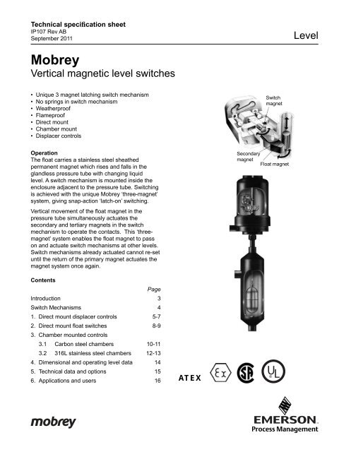
Operation<br />
The fl oat carries a stainless steel sheathed<br />
permanent magnet which rises and falls in the<br />
glandless pressure tube with changing liquid<br />
level. A switch mechanism is mounted inside the<br />
enclosure adjacent to the pressure tube. Switching<br />
is achieved with the unique <strong>Mobrey</strong> ‘three-magnet’<br />
system, giving snap-action ‘latch-on’ switching.<br />
<strong>Vertical</strong> movement of the fl oat magnet in the<br />
pressure tube simultaneously actuates the<br />
secondary and tertiary magnets in the switch<br />
mechanism to operate the contacts. This ‘threemagnet’<br />
system enables the fl oat magnet to pass<br />
on and actuate switch mechanisms at other levels.<br />
Switch mechanisms already actuated cannot re-set<br />
until the return of the primary magnet actuates the<br />
magnet system once again.<br />
Contents<br />
Introduction<br />
Page<br />
3<br />
Switch Mechanisms 4<br />
1. Direct mount displacer controls 5-7<br />
2. Direct mount fl oat switches<br />
3. Chamber mounted controls<br />
8-9<br />
3.1 Carbon steel chambers 10-11<br />
3.2 316L stainless steel chambers 12-13<br />
4. Dimensional and operating level data 14<br />
5. Technical data and options 15<br />
6. Applications and users 16<br />
ATEX<br />
Switch<br />
magnet<br />
Secondary<br />
magnet<br />
Float magnet<br />
U L<br />
<strong>Level</strong><br />
1
2<br />
Introduction<br />
Whether you require a switch for critical area<br />
applications or just general purpose control, the<br />
extensive range of <strong>Mobrey</strong> switches ensures that<br />
we will always have a solution to your particular<br />
problem.<br />
A choice of carbon steel chambers is available, or<br />
for more vigorous applications we supply a series of<br />
316 stainless steel chambers. A variety of tank and<br />
process connections is available to make installation<br />
simple and economic. This gives you the choice to<br />
meet your application in keeping with your budget.<br />
<strong>Mobrey</strong> vertical magnetic level switches for industrial<br />
and process control use have been available for<br />
over 20 years and have been steadily gaining a<br />
reputation for quality and reliability.<br />
Based on the industry standard boiler water level<br />
controls these controls employ the same three<br />
magnet switch mechanism for snap-action latching<br />
switching.<br />
The design of this unique switch mechanism<br />
overcomes all the inherent problems of mercury<br />
tubes and micro switches. Even under severe<br />
vibration conditions there are no springs to cause<br />
contact bounce, hover, or even failure. The snap<br />
action magnets give positive stable latching time<br />
after time after time.<br />
There are two switching functions available :<br />
2 x SPST (SPCO) switching or DPDT (DPCO)<br />
switching, and each comes in four variants :-<br />
• General purpose use with silver cadmium oxide<br />
contacts for long life.<br />
• Low power circuit with gold plated contacts for<br />
use in low current/voltage applications such as I.S.<br />
circuits.<br />
• High power circuits giving up to 10A switching<br />
capability.<br />
• Hermetically sealed for the ultimate in reliability<br />
- sealed for life.<br />
When controls are required to operate in extreme<br />
conditions, the unique <strong>Mobrey</strong> hermetically sealed<br />
switch provides dependable life long operation<br />
that you can rely on. With all its moving parts<br />
and contacts completely enclosed, this genuine<br />
hermetically sealed switch is suitable for use<br />
in corrosive atmospheres and low temperature<br />
environments.
Features<br />
• Relevant chambers are supplied CE marked<br />
and fully compliant with the Pressure Equipment<br />
Directive (97/23/EC)<br />
• Unique switching mechanism - totally reliable<br />
• No springs in switch mechanism - positive snap<br />
action switching<br />
• Vibration resistant - eliminates spurious trips<br />
• Multi-switching models - cost effective control<br />
• Genuine hermetically sealed switch option - totally<br />
safe and secure<br />
• Extensive range of chambers - suitable for most<br />
applications<br />
• Designed to ASME B31.3<br />
• Weld procedures approved to EN ISO 15614-1<br />
and ASME IX<br />
• Welders approved to EN 287-1<br />
• Material certifi cation to EN 10204, 3.1<br />
• Materials to ASTM and B.S. Standards<br />
Approvals<br />
Underwriters Laboratories (UL) Approval<br />
Explosion Proof for Class I, Div 1, Groups B, C & D<br />
Class II, Div 1, Groups E, F & G<br />
General Area, Weatherproof type NEMA 4<br />
Canadian Standards Association (CSA) Approval<br />
Explosion Proof for Class 1, Groups B, C & D<br />
General Area, Weatherproof to NEMA 4<br />
ATEX Approval<br />
Flame Proof ATEX II 1/2G, EExd IIC T6<br />
(-50°C≤Ta≤60°C)<br />
Intrinsically Safe Use<br />
For use in intrinsically safe circuits, gold plated<br />
switch contacts are recommended (see page 4).<br />
Users are reminded that it is their responsibility to<br />
obtain the necessary system approval and licences<br />
for such circuits.<br />
EN ISO 9001 : 2000<br />
<strong>Mobrey</strong> Ltd. has been assessed and approved by<br />
Lloyds Register Quality Assurance against BS EN<br />
9001 : 2000 for the design, development, assembly<br />
and re-calibration of precision instruments and<br />
systems for the measurement and indication of<br />
electrical signals, gas and liquid density, viscosity,<br />
pressure, level, fl ow and water/steam systems.<br />
Section through type H4 switch mechanism<br />
Hermetically sealed switch mechanism<br />
Quality Assurance<br />
With over 20 years worldwide experience in the<br />
major power, nuclear and petro-chemical industries,<br />
<strong>Mobrey</strong> Measurement is able to accommodate<br />
testing, surveying and documentation requirements<br />
as specifi ed at the time of order. Inspection by<br />
customers or nominated inspection agencies can be<br />
arranged.<br />
3
4<br />
<strong>Mobrey</strong> switch mechanisms<br />
4 contact type: D4, X4, P4, H4<br />
2 × independent SPST<br />
AA make on rise: BB Make on fall<br />
8 contact types: D8, X8, P8, H8<br />
Double pole double throw<br />
(4 × independent SPST)<br />
AA make on rise, BB make on<br />
fall<br />
Note: For DPDT operation,<br />
installer must common any<br />
one pair of A and B wires in the<br />
terminal block for each of the two<br />
Switch enclosures<br />
Enclosure modules<br />
R4N, S4N, L4N<br />
Ø 160<br />
Cable<br />
Entry<br />
1" NPT<br />
1" NPT<br />
Weatherproof industrial enclosure<br />
Ø 160<br />
Enclosure modules<br />
R7A, R7I, S7A, S7I<br />
Cable<br />
Entry<br />
1" NPT<br />
1" NPT<br />
R4N : 170<br />
S4N : 275<br />
L4N : 375<br />
Allow extra<br />
for cover<br />
removal<br />
Tube & Union<br />
R7A, R7I : 190<br />
S7A, S7I : 300<br />
Allow extra for<br />
cover removal<br />
Tube & Union<br />
Hazardous area enclosure<br />
Type D4, D8: General purpose switch mechanism.<br />
Type D4U, D8U: General purpose switch mechanism for UL & CSA<br />
Type X4, X8: High current switch mechanism.<br />
Type P4, P8: Switch mechanism with gold plated contacts for use in<br />
low power or intrinsically safe circuits.<br />
Type H4, H8: Hermetically sealed mechanism with gold plated<br />
contacts. All moving parts and contacts enclosed is an<br />
inert gas fi lled stainless steel enclosure. Suitable for<br />
use in low temperatures, contaminated atmospheres<br />
and intrinsically safe circuits.<br />
Electrical rating<br />
Type<br />
D4, D8<br />
D4U,D8U<br />
X4, X8<br />
P4, P8<br />
H4, H8<br />
Temp<br />
wetside<br />
º C<br />
400<br />
400<br />
250<br />
400<br />
250<br />
Low<br />
temp<br />
use<br />
No<br />
No<br />
No<br />
No<br />
-50 º C<br />
AC max. values<br />
VA<br />
2000<br />
2000<br />
2000<br />
6<br />
2000<br />
Volts<br />
440<br />
440<br />
440<br />
250<br />
440<br />
Amps<br />
5<br />
5<br />
10<br />
0.25<br />
5<br />
Each switch mechanism has fl ying leads which are factory wired to<br />
ceramic terminal blocks fi xed in the switch enclosure.<br />
Warning<br />
Gold plating on the contacts of P4 and P8 switch mechanisms may be<br />
permanently damaged if the mechanisms are used to switch circuits with<br />
values greater than those shown above.<br />
<strong>Switches</strong> must not be used for the direct starting of motors. Contacts<br />
should be wired in series with the operating coils of relays, contactor<br />
starters or solenoid valves and fused separately.<br />
Weatherprooof NEMA 4 / IP66.<br />
Aluminium alloy based/drawn steel cover.<br />
Type R4N: Fixed switch<br />
Type S4N: 94mm switch adjustment<br />
Type L4N: 194mm switch adjustment<br />
Flameproof & Explosion Proof (Weatherproof NEMA 4 / IP66)<br />
Aluminium alloy base and cover "A"<br />
Cast iron base and cover "I"<br />
Type R7A/R7I: Fixed switch<br />
Type S7A/S7I: 94mm switch adjustment<br />
Watts<br />
50<br />
50<br />
50<br />
3.6<br />
50<br />
DC max. values<br />
Volts<br />
250<br />
250<br />
250<br />
250<br />
250<br />
Res<br />
amps<br />
5<br />
5<br />
10<br />
0.25<br />
5<br />
Conduit entries<br />
Enclosures supplied with four contact switch mechanisms have a single<br />
1" NPT conduit entry.<br />
Enclosures supplied with eight contact switch mechanisms have 2 × 1"<br />
NPT conduit entries.<br />
Tube and Unions: 316 stainless steel throughout. Welded construction<br />
with additional swaging technique to ensure maximum integrity.<br />
Individually pressure tested to 150 bar (operating pressure will be limited<br />
by fl oat or fl ange specifi ed).<br />
Paint Finish: Black stove paint. Epoxy paint fi nishes available on<br />
request.<br />
Ind<br />
amps<br />
0.5<br />
0.5<br />
0.5<br />
0.1<br />
0.5
1.0 Direct mount displacer controls<br />
<strong>Mobrey</strong> displacer operated controls are ideal for sump<br />
application and other top mounting duties such as low<br />
level alarm in deep tanks. Their principle of operation<br />
also makes them suitable, in a modifi ed form, for very<br />
high pressure or low S.G. applications.<br />
The four most popular displacer arrangements are<br />
shown in this schematic diagram, which covers most<br />
of the likely applications. However, should you have a<br />
different requirement, we would be pleased to quote a<br />
model for your particular application.<br />
Principle of operation<br />
The displacer element, made of 316 stainless steel,<br />
is suspended on a stainless steel cable from a spring.<br />
The element is always heavier than its equivalent<br />
volume of the liquid in which it is to operate, and so will<br />
extend the tension spring at all times. In free air, the<br />
spring will be extended to a known length, controlled by<br />
a mechanical stop to prevent overstressing. Fixed to<br />
the spring is the fl oat rod and magnet assembly, free to<br />
move up and down as the spring extends or contracts,<br />
and outside the pressure tube in the usual manner is<br />
the switch mechanism.<br />
As liquid rises to cover the displacer element, a<br />
bouyancy force is created equal to the weight of the<br />
liquid displaced. This force in effect is seen by the<br />
spring as a reduction in weight, causing the spring to<br />
contract, hence moving the magnet upwards inside the<br />
pressure tube and actuating the switch mechanism.<br />
On a falling liquid level, the displacer element is<br />
uncovered and the spring sees an increasing effective<br />
weight, causing the spring to extend and move the<br />
magnet to re-set the switch mechanism (Fig i and v).<br />
This simple principle can be refi ned to operate a single<br />
switch over a very wide differential by providing the<br />
buoyancy force from two elements instead of just one<br />
(Fig ii).<br />
Two switch models are available for either two alarm<br />
duty with two narrow differentials (Fig iii) or for pump<br />
control/alarm duty with appropriate differentials (Fig iv).<br />
In all cases, because the elements are suspended<br />
on a cable, switching or control levels can be several<br />
metres below the mounting fl ange, and are fully fi eld<br />
Fig v<br />
One switch<br />
alarm<br />
differential<br />
Fig i<br />
One switch<br />
pump<br />
control<br />
Fig ii<br />
Two switch<br />
two alarm<br />
Fig iii<br />
Two switch<br />
alarm and<br />
pump control<br />
Fig iv<br />
Differential<br />
adjustable by re-setting the<br />
elements on the cable.<br />
Differential<br />
Differential<br />
No. 1<br />
Differential<br />
No. 2<br />
Alarm<br />
or pump<br />
differential<br />
Pump<br />
differential<br />
Displacer control<br />
5
6<br />
Displacer controls: ordering information<br />
Code Displacer operated alarm and pump control switches<br />
D Note 1<br />
Direct mount: Displacer controls<br />
Code Material of mounting fl ange<br />
C Carbon steel. ASTM A105 (For use +300ºC to -10ºC)<br />
S 316L stainless steel. ASTM A182: F316L (For use +300ºC to -50ºC)<br />
Code Displacer function and specifi cation<br />
Material of<br />
S.G. Range<br />
Elements Trim Spring 4 Contact 8 Contact<br />
11D<br />
316 S.S.<br />
0.6 - 1.2 0.75 - 1.2<br />
12D<br />
13D<br />
18D<br />
Function<br />
One switch<br />
narrow diff.<br />
One switch<br />
wide diff.<br />
Two switch<br />
2 wide diff.<br />
Two switch<br />
2 normal diff.<br />
316 S.S.<br />
316 S.S.<br />
316 S.S.<br />
316<br />
Stainless<br />
Steel<br />
Nimonic<br />
90<br />
0.5 - 1.2<br />
0.6 - 1.2<br />
0.6 - 1.2<br />
0.75 - 1.2<br />
0.8 - 1.2<br />
0.8 - 1.2<br />
Operating<br />
temp. range<br />
-50ºC to +300ºC<br />
-50ºC to +300ºC<br />
-50ºC to +300ºC<br />
-50ºC to +300ºC<br />
Max. pres.<br />
20ºC<br />
Code Switch enclosure<br />
Material of Material of Switch Max. no. of switch<br />
Duty Base Cover wetted parts adjustment mechanisms<br />
S4N Weather proof Aluminium Drawn<br />
Adjust<br />
Note 2 alloy steel<br />
switching point<br />
S7A Flame proof Aluminium Aluminium 316 by moving<br />
2<br />
&<br />
Note 2 alloy alloy stainless displacer elements<br />
S7I Explosion proof Cast iron Cast iron steel on cable<br />
Code Approvals<br />
U UL Explosion Proof<br />
C CSA Explosion Proof<br />
N UL & CSA General Area, Weatherproof type NEMA 4<br />
ATEX Flameproof & Weatherproof IP66 depending on switch enclosure (leave blank)<br />
Code Number of switch mechanisms<br />
1 Specify 1 for single switch models 11D, 12D<br />
2 Specify 2 for two switch models 13D, 18D<br />
Code Type of switch mechanism<br />
Switch mechanism Max. wetside A.C. max. values D.C. max. values<br />
duty<br />
4 Contact: 2 × SPST<br />
temperature Volts Amps VA Volts Res. I Ind. I Watts<br />
D4 General purpose 300ºC 440 5 2000 250 5 0.5 50<br />
D4U Gen. purpose for UL<br />
& CSA<br />
300ºC 400 5 2000 250 5 0.5 50<br />
P4 Low power circuits 300ºC 250 0.25 6 250 0.25 0.1 3.6<br />
X4 High power circuits 250ºC 440 10 2000 250 10 0.5 50<br />
H4 Hermetically sealed<br />
8 Contact: DPDT<br />
250ºC 440 5 2000 250 5 0.5 50<br />
D8 General purpose 300ºC 440 5 2000 250 5 0.5 50<br />
D8U Gen. purpose for UL<br />
& CSA<br />
300ºC 440 5 2000 250 5 0.5 50<br />
P8 Low power circuits 300ºC 250 0.25 6 250 0.25 0.1 3.6<br />
X8 High power circuits 250ºC 440 10 2000 250 10 0.5 50<br />
H8 Hermetically sealed 250ºC 440 5 2000 250 5 0.5 50<br />
Code Mounting arrangement<br />
0 1" N.P.T. Thread: 316 stainless steel standard These are our<br />
60 3" Class 150 RF stocked fl anges.<br />
61 3" Class 300 RF Other fl ange<br />
62 3" Class 600 RF sizes and ratings<br />
65 4" Class 150 RF are available<br />
66 4" Class 300 RF on<br />
67 4" Class 600 RF request.<br />
� � � � � � � �<br />
D C 13D S7A U 2 D4 / 60 Typical ordering information<br />
Notes:<br />
1. Supplied with 3m 316 stainless steel displacer cable as standard. Other lengths available on request.<br />
2. Base material will be cast iron whenever 8 contact switches are specifi ed<br />
Customers must state operating pressure, temperature and specifi c gravity, together with function of each switch mechanism when ordering.<br />
Due to component tolerances, dimensions DB, E and S given on page 7 are approximate and may vary on each control by up to 10mm. Setting the control to<br />
operate at the required level can be achieved on site by adjusting the element up or down on the cable as necessary.<br />
102<br />
bar
Displacer types and dimensional details<br />
Single switch narrow differential: 11D<br />
Specify for alarm duty.<br />
Switching level can be changed by<br />
simply moving the displacer up or<br />
down the cable.<br />
11D St. Steel : A = 216 � = 60.3<br />
Switch<br />
types<br />
S.G.<br />
S min<br />
E<br />
S min = Adjustable distance to upper<br />
switching level.<br />
E min = Differential<br />
DB = Minimum dead band<br />
Two switch 2 narrow differentials: 18D<br />
The displacers are positioned to form<br />
two elements of similar lengths, such<br />
that two alarm points may be given.<br />
This arrangement is typical of sump<br />
application.<br />
18D St. Steel: A = 216 � = 60.3<br />
Switch<br />
types<br />
S.G.<br />
S min<br />
E min<br />
Dead band<br />
D4<br />
D4U<br />
0.6<br />
315<br />
90<br />
D4<br />
D4U<br />
0.6<br />
390<br />
90<br />
200<br />
P4 X4 H4<br />
0.75<br />
335<br />
70<br />
P4 X4 H4<br />
0.8<br />
385<br />
70<br />
230<br />
1.0<br />
365<br />
60<br />
1.0<br />
375<br />
60<br />
255<br />
4 Contact:<br />
D4 D4U P4 X4 H4<br />
2 × independent SPST<br />
AA make on rise:<br />
BB Make on fall<br />
1.2<br />
380<br />
55<br />
1.2<br />
365<br />
55<br />
310<br />
D8 P8 X8 H8<br />
D8U<br />
0.75<br />
275<br />
135<br />
D8U<br />
0.8<br />
355<br />
135<br />
165<br />
1.0<br />
320<br />
105<br />
1.0<br />
350<br />
105<br />
215<br />
1.2<br />
340<br />
90<br />
D8 P8 X8 H8<br />
1.2<br />
345<br />
90<br />
250<br />
Single switch wide differential: 12D<br />
The two displacer elements are<br />
positioned at any point on the cable<br />
to correspond to the switching levels<br />
required. When the liquid level drops<br />
to the lower displacer the switch<br />
is actuated and starts (or stops) a<br />
pump; when the liquid rises to the<br />
upper displacer the switch is again<br />
actuated to stop (or start) the pump.<br />
12D St. Steel: A = 216 � = 60.3<br />
Switch<br />
types<br />
D4<br />
D4U<br />
P4 X4 H4 D8<br />
D8U<br />
Two switch 2 wide differentials: 13D<br />
A pump is controlled between the<br />
middle and the lower pump displacers<br />
positioned on the cable at the required<br />
levels. Should the level rise to the<br />
upper displacer this actuates the<br />
upper alarm switch which remains<br />
actuated until the level drops to the<br />
middle displacer.<br />
Alternatively, the upper switch could<br />
control a second pump.<br />
Switch<br />
types<br />
S.G.<br />
S min<br />
E min<br />
D4<br />
D4U<br />
P4 X4 H4<br />
Switch mechanisms Switch enclosures<br />
Double pole double throw<br />
(4 × independent SPST)<br />
AA make on rise,<br />
BB make on fall<br />
�<br />
S<br />
A E<br />
A<br />
A<br />
�<br />
S<br />
E<br />
DB<br />
8 Contact:<br />
D8 D8U P8 X8 H8<br />
E<br />
S.G.<br />
S min<br />
E min<br />
13D St. Steel: A = 152 B = 304 � = 60.3<br />
Dead band<br />
Ø 160<br />
Cable<br />
Entry<br />
1" NPT<br />
1" NPT<br />
0.5<br />
415<br />
165<br />
0.6<br />
390<br />
135<br />
220<br />
0.8<br />
430<br />
110<br />
0.8<br />
385<br />
110<br />
255<br />
Weatherproof:<br />
S4N<br />
1.0<br />
430<br />
95<br />
S4N : 275<br />
Allow extra<br />
for cover<br />
removal<br />
Tube & Union<br />
1.0<br />
375<br />
95<br />
285<br />
1.2<br />
425<br />
80<br />
1.2<br />
365<br />
80<br />
310<br />
Ø 180<br />
Cable<br />
entry<br />
1" NPT<br />
0.75<br />
390<br />
205<br />
D8U<br />
0.8<br />
355<br />
200<br />
165<br />
A<br />
A<br />
�<br />
P8 X8 H8<br />
A<br />
B<br />
A<br />
D8 P8 X8 H8<br />
1.0<br />
350<br />
145<br />
215<br />
Flameproof:<br />
S7A S7I<br />
1" NPT<br />
0.8<br />
390<br />
200<br />
1.0<br />
400<br />
165<br />
�<br />
S<br />
E<br />
1.2<br />
400<br />
140<br />
S<br />
E<br />
DB<br />
E<br />
1.2<br />
345<br />
140<br />
250<br />
S7A, S7I: 300<br />
Allow extra<br />
for cover<br />
removal<br />
Tube and union<br />
7
8<br />
2.0 Direct Mounting Float <strong>Switches</strong>: Ordering Information<br />
C Carbon steel ASTM A105 (for use + 400oC to -10oC) S 316L stainless steel ASTM A182: F316L (for use + 400oC to -101o Code Float operated alarm and pump control switches<br />
D Direct mount: Float switches<br />
Code Material of mounting fl ange<br />
C)<br />
Code Floats<br />
11F<br />
12F<br />
13F<br />
14F<br />
Minimum<br />
S.G.<br />
0.80<br />
0.75<br />
0.65<br />
0.54<br />
20°C<br />
34.5<br />
102.1<br />
51.1<br />
19.6<br />
Code Switch Enclosure<br />
R4N<br />
S4N<br />
L4N<br />
R7A<br />
S7A<br />
R7I<br />
S7I<br />
Duty<br />
Weatherproof<br />
IP66<br />
Flameproof<br />
&<br />
Explosionproof<br />
Pressure rating (bar)<br />
Code Approvals<br />
U UL Explosion Proof<br />
C CSA Explosion Proof<br />
N UL & CSA General Area, Weatherproof type NEMA 4<br />
ATEX Flameproof & Weatherproof IP66 depending on switch enclosure (leave blank)<br />
Code Number of switch mechanisms<br />
1-6 As required: see max. number allowable in switch enclosure data above<br />
Code Type of switch mechanism<br />
D4<br />
D4U<br />
P4<br />
X4<br />
H4<br />
D8<br />
D8U<br />
P8<br />
X8<br />
H8<br />
250°C<br />
22.5<br />
66.3<br />
33.2<br />
12.7<br />
Material<br />
of base<br />
Aluminium<br />
alloy*<br />
Aluminium<br />
alloy*<br />
Cast<br />
iron<br />
400°C<br />
20.0<br />
59.2<br />
29.6<br />
11.3<br />
Material<br />
of cover<br />
Drawn<br />
steel<br />
Aluminium<br />
alloy<br />
Cast<br />
iron<br />
Switch mechanism<br />
duty<br />
4 contact: 2 x SPST<br />
General purpose<br />
Gen. purpose for UL<br />
& CSA<br />
Low power circuits<br />
High power circuits<br />
Hermetically sealed<br />
8 contact: DPDT<br />
General purpose<br />
Gen. purpose for UL<br />
& CSA<br />
Low power circuits<br />
High power circuits<br />
Hermetically sealed<br />
Float<br />
diameter<br />
67<br />
90<br />
88<br />
88<br />
Material of<br />
wetted parts<br />
316<br />
stainless<br />
steel<br />
Code Mounting arrangement<br />
0 1" NPT thread: 316 stainless steel standard<br />
60 3" Class 150RF<br />
61 3" Class 300RF<br />
62 3" Class 600RF<br />
65 4" Class 150RF<br />
66 4" Class 300RF<br />
67 4" Class 600RF<br />
Note :<br />
*Base material will be cast iron whenever 8 contact switches specifi ed.<br />
Instrument pressure rating is the lower of either the fl oat or mounting fl ange<br />
Max.<br />
wetside<br />
temp.<br />
400oC 400o Volts<br />
440<br />
C 440<br />
400 o C<br />
250 o C<br />
250 o C<br />
400 o C<br />
400 o C<br />
400 o C<br />
250 o C<br />
250 o C<br />
Matching<br />
enclosures<br />
All models<br />
AC max values<br />
Amps VA<br />
These are our<br />
stocked fl anges.<br />
Other fl ange<br />
sizes and ratings<br />
are available on<br />
request<br />
���<br />
��� ��� ��� ��� ��� ��� ���<br />
D C 12F L4N U 4 D4 / 67 Typical ordering information<br />
250<br />
440<br />
440<br />
440<br />
440<br />
250<br />
440<br />
440<br />
Switch<br />
adjustment<br />
None<br />
94mm<br />
194mm<br />
None<br />
94mm<br />
None<br />
94mm<br />
5<br />
5<br />
0.25<br />
10<br />
5<br />
5<br />
5<br />
0.25<br />
10<br />
5<br />
2000<br />
2000<br />
6<br />
2000<br />
2000<br />
2000<br />
2000<br />
6<br />
2000<br />
2000<br />
Matching<br />
mounting fl anges<br />
3" NB and larger<br />
4" NB minimum<br />
Max. no. of switches<br />
4 Contact<br />
1<br />
4<br />
6<br />
1<br />
4<br />
1<br />
4<br />
DC max values<br />
Volts Res. I Ind. I Watts<br />
250<br />
250<br />
250<br />
250<br />
250<br />
250<br />
250<br />
250<br />
250<br />
250<br />
5<br />
5<br />
0.25<br />
10<br />
5<br />
5<br />
5<br />
0.25<br />
10<br />
5<br />
8 Contact<br />
1<br />
2<br />
3<br />
1<br />
2<br />
1<br />
2<br />
0.5<br />
0.5<br />
0.1<br />
0.5<br />
0.5<br />
0.5<br />
0.5<br />
0.1<br />
0.5<br />
0.5<br />
50<br />
50<br />
3.6<br />
50<br />
50<br />
50<br />
50<br />
3.6<br />
50<br />
50
Direct Mounting Float Dimensions<br />
11F<br />
H dimension<br />
when used<br />
with:<br />
R4N R7A R7I<br />
S4N S7A S7I<br />
L4N<br />
Floats for 3" NB mounting: 11F Floats for 4" NB mounting: 12F, 13F, 14F<br />
*Float rod may be shortened to suit *Float rod may be shortened to suit<br />
min H<br />
155<br />
155<br />
11F<br />
Switch Enclosures<br />
Switch Mechanisms<br />
max H<br />
315<br />
315<br />
Switch<br />
adjustment<br />
None<br />
94mm<br />
Wet<br />
switching<br />
differential<br />
20mm<br />
104mm max.<br />
min H<br />
155<br />
155<br />
155<br />
12F 13F 14F<br />
max H<br />
415<br />
415<br />
415<br />
Switch<br />
adjustment<br />
None<br />
94mm<br />
194mm<br />
Weatherproof: R4N S4N L4N Flameproof: R7A R7I S7A S7I<br />
Ø 160<br />
Cable<br />
entry<br />
1" NPT<br />
1" NPT<br />
H+35<br />
Ø67<br />
R4N: 170<br />
S4N: 275<br />
L4N: 375<br />
Allow extra<br />
for cover<br />
removal<br />
Tube and union<br />
4 Contact D4, D4U, P4, X4, H4<br />
2 x independent SPST<br />
AA make on rise: BB make on fall<br />
H*<br />
150<br />
12F, 13F, 14F<br />
Ø 180<br />
Cable entry<br />
1" NPT<br />
1" NPT<br />
H+35<br />
Ø88<br />
Ø90<br />
Tube and union<br />
8 Contact D8, D8U, P8, X8, H8<br />
Double pole double throw<br />
(4 x independent SPST)<br />
AA make on rise: BB make on fall<br />
H*<br />
160<br />
Wet<br />
switching<br />
differential<br />
20mm<br />
104mm max.<br />
214mm max.<br />
R7A, R7I: 190<br />
S7A, S7I: 300<br />
Allow extra<br />
for cover<br />
removal<br />
9
10<br />
3.0 Carbon Steel Chamber Mounted Controls: Ordering Information<br />
Code Chamber mounted controls<br />
B Bottle Style: Float sealed inside chamber during manufacture<br />
X Flanged Style: Float may be removed from chamber for routine maintenance<br />
Code Material of contruction of chamber<br />
C Carbon steel: See page 15<br />
Code Floats<br />
Float & trim Minimum Flanged style chambers (X) Flanged process connection Thead/Sock. connection Chamber<br />
material S.G Pressure rating (bar) Pressure rating (bar) Pressure rating (bar) body<br />
20ºC 250ºC 400ºC 20ºC 250ºC 400ºC 20ºC 250ºC 400ºC size<br />
11F<br />
0.80 34.5 22.5 20.0 30.1 22.5 20.0 30.1 22.5 20.0 3" N.B.<br />
12F 316 0.75 102.1 66.3 59.2 88.8 66.3 59.2 88.8 66.3 59.2<br />
13F stainless 0.65 51.1 33.2 29.6 44.6 33.2 29.6 44.6 33.2 29.6<br />
14F steel 0.54 19.6 12.1 6.5 17.1 12.7 6.5 17.1 12.7 6.5 4" N.B.<br />
17D<br />
0.40 102.1 66.3 59.2 88.8 66.3 59.2 88.8 66.3 59.2<br />
Code Switch Enclosure<br />
Material of Material of Switch<br />
Max. no. of switches<br />
Duty Base Cover wetted parts adjustment 4 Contact 8 Contact<br />
R4N Weatherproof Aluminium Drawn 316<br />
None<br />
1<br />
1<br />
S4N IP66 alloy* steel stainless 94mm<br />
4<br />
2<br />
R7A<br />
Aluminium Aluminium steel<br />
None<br />
1<br />
1<br />
S7A Flameproof alloy* alloy<br />
94mm<br />
4<br />
2<br />
R7I &<br />
Cast Cast<br />
None<br />
1<br />
1<br />
S7I Explosionproof<br />
Code Approvals<br />
iron iron<br />
94mm<br />
4<br />
2<br />
U UL Explosion Proof<br />
C CSA Explosion Proof<br />
N UL & CSA General Area, Weatherproof type NEMA 4<br />
ATEX Flameproof & Weatherproof IP66 depending on switch enclosure (leave blank)<br />
Code Number of switch mechanisms<br />
1 - 4 As required: see max. number allowable in switch enclosure and fl oat data above<br />
Code Type of switch mechanism<br />
Switch mechanism Max. wetside A.C. max. values D.C. max. values<br />
duty<br />
4 Contact: 2 × SPST<br />
temperature Volts Amps VA Volts Res. I Ind. I Watts<br />
D4 General purpose<br />
400ºC 440 5 2000 250 5 0.5 50<br />
D4U Gen. purpose for UL &<br />
CSA<br />
400ºC 440 5 2000 250 5 0.5 50<br />
P4 Low power circuits<br />
400ºC 250 0.25 6 250 0.25 0.1 3.6<br />
X4 High power circuits<br />
250ºC 440 10 2000 250 10 0.5 50<br />
H4 Hermetically sealed<br />
8 Contact: DPDT<br />
250ºC 440 5 2000 250 5 0.5 50<br />
D8 General purpose<br />
400ºC 440 5 2000 250 5 0.5 50<br />
D8U Gen. purpose for UL &<br />
CSA<br />
400ºC 440 5 2000 250 5 0.5 50<br />
P8 Low power circuits<br />
400ºC 250 0.25 6 250 0.25 0.1 3.6<br />
X8 High power circuits<br />
250ºC 440 10 2000 250 10 0.5 50<br />
H8 Hermetically sealed 250ºC 440 5 2000 250 5 0.5 50<br />
Code <strong>Process</strong> connection confi guration<br />
1 Side/bottom<br />
2 Side/side with 1" NPT drain<br />
Code <strong>Process</strong> connection size & rating<br />
Chamber : 3" & 4" N.B. Code Chamber : 4" N.B.only These are our<br />
01 1" N.P.T.: 316 s/s Std. 21 1½" Class 150 RF stocked sizes.<br />
11 1" Class 150 RF 22 1½" Class 300 RF Other fl ange<br />
12 1" Class 300 RF 23 1½" Class 600 RF sizes and ratings<br />
13 1" Class 600 RF 25 DN40 PN16<br />
are available<br />
15 DN25 PN16<br />
31 2" Class 150 RF on request.<br />
16 DN25 PN25<br />
32 2" Class 300 RF Instrument<br />
17 DN25 PN40<br />
33 2" Class 600 RF pressure<br />
18 DN25 PN64<br />
35 DN50 PN16<br />
rating is the lower<br />
19 DN25 PN100<br />
36 DN50 PN25<br />
of either the fl oat<br />
37 DN50 PN40<br />
or process fl ange.<br />
��� ��� ��� ��� ��� ��� ��� ��� ���<br />
X C 14F S7A 2 D4 / 2 01 Typical ordering information<br />
Note:<br />
* Base material will be cast iron whenever 8 contact switches are specifi ed.<br />
State process connection centres when ordering. See page 14 for standard dimensions. Instrument pressure rating is the lower of either the fl oat or the process
Carbon steel: Bottle construction<br />
BC<br />
Float is sealed inside chamber during manufacture<br />
Ø 160<br />
Cable entry<br />
1" NPT<br />
Weatherproof: R4N S4N<br />
1" NPT<br />
Chamber Type and Material of Construction<br />
R4N: 170<br />
S4N: 275<br />
Allow extra<br />
for cover<br />
removal<br />
Tube and union<br />
4 contact: D4 D4U P4 X4 H4<br />
2 × independent SPST<br />
AA make on rise: BB make on fall<br />
Switch Enclosures<br />
Switch Mechanisms<br />
Carbon steel: Flanged construction<br />
XC<br />
Float may be removed from chamber for routine<br />
maintenance, cleaning or inspection<br />
Flameproof: R7A S7A R7I S7I<br />
Cable entry<br />
1" NPT<br />
1" NPT<br />
8 contact: D8 D8U P8 X8 H8<br />
Double pole double throw (4 × independent SPST)<br />
AA make on rise: BB make on fall<br />
<strong>Process</strong> Connection Confi guration<br />
Side and Bottom - 1 Side and Side with Drain - 2<br />
Chamber dimensions, operating levels and technical data are given on page 14<br />
Ø 180<br />
Tube and union<br />
R7A, R7I: 190<br />
S7A, S7I: 300<br />
Allow extra<br />
for cover<br />
removal<br />
11
12<br />
4.0 316L Stainless Steel Chamber Mounted Controls: Ordering Information<br />
Code Chamber mounted controls<br />
B Bottle Style: Float sealed inside chamber during manufacture<br />
X Flanged Style: Float may be removed from chamber for routine maintenance<br />
Code Material of contruction of chamber<br />
S 316L stainless steel: see page 15<br />
Code Floats<br />
Float & trim Min. Flanged style chambers (X) Flanged process connection Thread/Sock. connection Chamber<br />
material S.G Pressure rating (bar) Pressure rating (bar) Pressure rating (bar)<br />
body<br />
20ºC 250ºC 400ºC 20ºC 250ºC 400ºC 20ºC 250ºC 400ºC size<br />
12F 316 0.75 82.7 54.9 48.6 82.7 54.9 48.6 88.8 66.3 59.2<br />
13F stainless 0.65 41.4 27.5 24.3 41.4 27.5 24.3 44.6 33.2 29.6<br />
14F steel 0.54 15.9 10.5 6.5 15.9 10.5 6.5 17.1 12.7 11.3 4" N.B.<br />
17D<br />
0.40 82.7 54.9 48.6 82.7 54.9 48.6 88.8 66.3 59.2<br />
Code Switch Enclosure<br />
Material of Material of Switch Max. no. of switches<br />
Duty Base Cover wetted parts adjustment 4 Contact 8 Contact<br />
R4N Weatherproof Aluminium Drawn<br />
None 1<br />
1<br />
S4N<br />
R7A<br />
S7A<br />
R7I<br />
S7I<br />
IP66<br />
Flameproof<br />
&<br />
Explosionproof<br />
Code Approvals<br />
alloy*<br />
Aluminium<br />
alloy*<br />
Cast<br />
iron<br />
steel<br />
Aluminium<br />
alloy<br />
Cast<br />
iron<br />
316<br />
stainless<br />
steel<br />
94mm<br />
None<br />
94mm<br />
None<br />
94mm<br />
4<br />
1<br />
4<br />
1<br />
4<br />
2<br />
1<br />
2<br />
1<br />
2<br />
U UL Explosion Proof<br />
C CSA Explosion Proof<br />
N UL & CSA General Area, Weatherproof type NEMA 4<br />
ATEX Flameproof & Weatherproof IP66 depending on switch enclosure (leave blank)<br />
Code Number of switch mechanisms<br />
1 - 4 As required: see max. number allowable in switch enclosure and fl oat data above<br />
Code Type of switch mechanism<br />
Switch mechanism Max. wetside A.C. max. values D.C. max. values<br />
duty<br />
4 Contact: 2 × SPST<br />
temperature Volts Amps VA Volts Res. I Ind. I Watts<br />
D4 General purpose 400ºC 440 5 2000 250 5 0.5 50<br />
D4U Gen. purpose for UL<br />
and CSA<br />
400ºC 440 5 2000 250 5 0.5 50<br />
P4 Low power circuits 400ºC 440 0.25 6 250 0.25 0.1 3.6<br />
X4 High power circuits 250ºC 250 10 2000 250 10 0.5 50<br />
H4 Hermetically sealed<br />
8 Contact: DPDT<br />
250ºC 440 5 2000 250 5 0.5 50<br />
D8 General purpose 400ºC 440 5 2000 250 5 0.5 50<br />
D8U Gen. purpose for UL<br />
and CSA<br />
400ºC 440 5 2000 250 5 0.5 50<br />
P8 Low power circuits 400ºC 250 0.25 6 250 0.25 0.1 3.6<br />
X8 High power circuits 250ºC 440 10 2000 250 10 0.5 50<br />
H8 Hermetically sealed 250ºC 440 5 2000 250 5 0.5 50<br />
Code <strong>Process</strong> connection confi guration<br />
1 Side/bottom<br />
2 Side/side with 1" NPT drain<br />
Code <strong>Process</strong> connection size & rating<br />
01 1" N.P.T. 316 stainless steel standard 22 1½" Class 300 RF<br />
11 1" Class 150 RF<br />
23 1½" Class 600 RF<br />
12 1" Class 300 RF<br />
31 2" Class 150 RF<br />
13 1" Class 600 RF<br />
32 2" Class 300 RF<br />
21 1½" Class 150 RF<br />
33 2" Class 600 RF<br />
� � � � � � � � �<br />
B S 17D R4N U 1 X8 / 2 33 Typical ordering information<br />
Note:<br />
* Base material will be cast iron whenever 8 contact switches are specifi ed<br />
State process connection centres when ordering. See page 14 for standard dimensions. Instrument pressure rating is the<br />
lower of either the fl oat or the process fl ange.
Carbon steel: Bottle construction<br />
BS<br />
Float is sealed inside chamber during manufacture<br />
Ø 160<br />
Cable entry<br />
1" NPT<br />
Chamber Type and Material of Construction<br />
Carbon steel: Flanged construction<br />
XS<br />
Float may be removed from chamber for routine<br />
maintenance, cleaning or inspection<br />
Switch Enclosures<br />
Weatherproof: R4N S4N Flameproof: R7A S7A R7I S7I<br />
1" NPT<br />
R4N: 170<br />
S4N: 275<br />
Allow extra<br />
for cover<br />
removal<br />
Tube and union<br />
4 contact: D4 D4U P4 X4 H4<br />
2 × independent SPST<br />
AA make on rise: BB make on fall<br />
Switch Mechanisms<br />
Cable entry<br />
1" NPT<br />
1" NPT<br />
8 contact: D8 D8U P8 X8 H8<br />
Double pole double throw (4 × independent SPST)<br />
AA make on rise: BB make on fall<br />
<strong>Process</strong> Connection Confi guration<br />
Side and Bottom - 1 Side and Side with Drain - 2<br />
Chamber dimensions, operating levels and technical data are given on page 14<br />
Ø 180<br />
Tube and union<br />
R7A, R7I: 190<br />
S7A, S7I: 300<br />
Allow extra<br />
for cover<br />
removal<br />
13
14<br />
Dimensional and Operating <strong>Level</strong> Data<br />
C<br />
D<br />
B<br />
G<br />
F<br />
A<br />
Screwed Flanged<br />
0.4<br />
65<br />
118<br />
0.5<br />
73<br />
122<br />
0.7<br />
91<br />
132<br />
0.8<br />
100<br />
137<br />
Style 2: Side and Side<br />
A B* C D E F<br />
<strong>Process</strong><br />
connections<br />
Single<br />
switch<br />
Multitype<br />
Chamber<br />
type<br />
Single<br />
switch<br />
Multiswitch<br />
Single<br />
switch<br />
Multiswitch<br />
Chamber type<br />
‘R’ head ‘S’ head BC/others ‘R’ head ‘S’ head ‘R’ head ‘S’ head BC/BS XC/XS<br />
1" NPT (side/bottom) 300 385 76/95 50 70 155 - - 48/160 225<br />
1" NPT (side/side) - - 95 50 70 155 271 356 160 225<br />
1" 150<br />
356 441 110 50 70 155 271 356 160 225<br />
1" 300<br />
356 441 117 50 70 155 271 356 160 225<br />
1" 600<br />
356 441 123 50 70 155 271 356 160 225<br />
DN25 PN16<br />
356 441 94 50 70 155 271 356 160 225<br />
DN25 PN25<br />
356 441 96 50 70 155 271 356 160 225<br />
DN25 PN40<br />
356 441 96 50 70 155 271 356 160 225<br />
DN25 PN64<br />
356 441 114 50 70 155 271 356 160 225<br />
DN25 PN100<br />
356 441 114 50 70 155 271 356 160 225<br />
1½" 150<br />
356 441 115 50 70 155 271 356 160 225<br />
1½" 300<br />
356 441 121 50 70 155 271 356 160 225<br />
1½" 600<br />
356 441 126 50 70 155 271 356 160 225<br />
DN40 PN16<br />
356 441 97 50 70 155 271 356 160 225<br />
2" 150<br />
356 441 112 50 70 155 271 356 160 225<br />
2" 300<br />
356 441 118 50 70 155 271 356 160 225<br />
2" 600<br />
356 441 129 50 70 155 271 356 160 225<br />
DN50 PN16<br />
356 441 98 50 70 155 271 356 160 225<br />
DN50 PN25<br />
356 441 101 50 70 155 271 356 160 225<br />
B* Dimension given is for 4" NB chamber (12F, 13F, 14F & 17D Floats). For 3" NB chamber (11F Float) subtract 13mm.<br />
Operating levels: Type 17D fl oat in any chamber.<br />
Operating S.G.<br />
Dimension C<br />
Dimension D<br />
Style 1: Side and Bottom<br />
Notes: C = Highest operating liquid level D (Multi switch) = Lowest operating liquid level<br />
D (Single switch) = Reset level D-C = Wet switching differential (max)<br />
All dimensions in mm.<br />
0.9<br />
109<br />
141<br />
NOTE: Dimensions given are for reference only, and must be certifi ed on order.<br />
Dimensional data: enclosures<br />
Type<br />
R7A, R7I<br />
S7A, S7I<br />
R4N<br />
S4N<br />
L4N<br />
B<br />
G<br />
F<br />
A<br />
Duty<br />
Flameproof<br />
&<br />
Explosion proof<br />
Weatherproof<br />
0.6<br />
82<br />
127<br />
Height G<br />
190<br />
300<br />
170<br />
275<br />
375<br />
Conduit thread*<br />
1" NPT<br />
1" NPT<br />
Drain<br />
1" NPT<br />
B<br />
1.0<br />
118<br />
147<br />
Switch adjustment<br />
None<br />
94<br />
None<br />
94<br />
194<br />
G<br />
F<br />
E<br />
160<br />
C<br />
D<br />
Drain<br />
1" NPT<br />
1.1<br />
127<br />
152<br />
B<br />
G<br />
F<br />
E<br />
160<br />
1.2<br />
136<br />
156<br />
Weatherproof rating<br />
IP66 to IEC60529<br />
(NEMA 4)<br />
IP66 to IEC60529<br />
(NEMA 4)<br />
*Enclosures for use with 8 contact switch mechanisms have both conduit entries threaded, whilst those for use<br />
with 4 contact switch mechanisms have only one conduit entry.
Technical Data<br />
<strong>Mobrey</strong> vertical level controls are manufactured to the<br />
highest standards of quality with only certifi ed materials:<br />
BS EN 10204 : 2004-3.1. Design of <strong>Mobrey</strong> chambers is<br />
in accordance with ASME B31.3. Relevant chambers are<br />
supplied CE marked and fully compliant with the Pressure<br />
Equipment Directive (97/23/EC).<br />
Weld procedures approved to EN ISO 15614-1 and ASME<br />
IX, welders approved to BSEN 287-1. Circumferential and<br />
set-on branch welds are full penetration welds, with visual<br />
inspection in accordance with ASME B31.3 "normal service"<br />
requirements and our company standard 417.<br />
All pressure retaining assemblies are hydrostatically<br />
pressure tested to a minimum of 1.43 × maximum working<br />
pressure or to fl ange standard requirements.<br />
Radiography or other NDT techniques can be<br />
accommodated provided that they are specifi ed at time of<br />
order entry.<br />
Inspection<br />
Whilst <strong>Mobrey</strong> employ inspectors in house, unconnected<br />
with production, customers frequently ask for outside<br />
inspection. We are happy to accommodate nominated<br />
inspectors if agreed at order entry.<br />
Some specifi cations require a quality control plan detailing<br />
inspection points and hold points. <strong>Mobrey</strong> will produce these<br />
QC plans for customer approval if agreed at order entry.<br />
Pressure Ratings (bar)<br />
Material Carbon steel: A105 Stainless steel: 316L<br />
ASME B16.5 Class 150<br />
ASME B16.5 Class 300<br />
ASME B16.5 Class 600<br />
BS EN 1092-1 PN16<br />
BS EN 1092-1 PN25<br />
BS EN 1092-1 PN40<br />
20ºC<br />
19.6<br />
51.1<br />
102.1<br />
16<br />
25<br />
40<br />
250ºC<br />
12.1<br />
41.9<br />
83.9<br />
14.4<br />
22.5<br />
36<br />
400ºC<br />
6.5<br />
34.7<br />
69.4<br />
10.8<br />
16.9<br />
27<br />
20ºC<br />
15.9<br />
41.4<br />
82.7<br />
12.3<br />
19.2<br />
30.6<br />
250ºC<br />
10.5<br />
27.5<br />
54.9<br />
7.9<br />
12.4<br />
19.8<br />
400ºC<br />
6.5<br />
24.3<br />
48.6<br />
6.8<br />
10.7<br />
17.1<br />
Technical specifi cation<br />
Materials of construction Carbon steel chamber Stainless steel chamber<br />
Chamber tube ASTM A106 grade B ASTM A312 TP316L<br />
Top casting ASTM A216 - -<br />
Top/bottom caps ASTM A105 ASTM A182 F316L / A403 WP316L<br />
Top cover ASTM A105 ASTM A182 F316L<br />
Flanges/fi ttings ASTM A105 ASTM A182 F316<br />
Studs ASTM A193-B7 ASTM A320-L7<br />
Nuts ASTM A194-2H ASTM A194 Grade 7+S3<br />
Standard carbon steel chambers +400ºC to -10ºC. Stainless steel chambers +400°C to -101°C<br />
Pressure tube & union.<br />
Swaged & welded<br />
construction<br />
Magnet sheathed in<br />
316 st. steel<br />
‘0’ ring seal to base<br />
Full<br />
penetration<br />
welding<br />
Weld neck<br />
fl anges used<br />
throughout<br />
Options<br />
• Low temperature carbon steel • Ratings up to ASME Class 2500 • N.A.C.E. requirements<br />
• <strong>Process</strong> connections to specifi cation • Cr. mo. steels • N.D.T. to your specifi cations<br />
• Duplex UNS31803 • 3.1 Identifi able certifi cation • Vent and drain connections<br />
Float<br />
15
16<br />
<strong>Level</strong><br />
<strong>Mobrey</strong> “Fit and Forget” Products Provide The Solution To Your Liquid <strong>Level</strong> Control Problems<br />
Medium pressures<br />
ASME Class 150, 300 600<br />
SG 0.4<br />
Pages 10-13<br />
You can rely on us<br />
The <strong>Mobrey</strong> range of vertical liquid level controls<br />
is designed for operation in a wide variety of<br />
applications.<br />
Typical Applications<br />
Separators Water Sumps<br />
Compressors Scrubbers<br />
Knock-out Pots Fractioning Columns<br />
Condensors Flash Vessels<br />
De-aerators <strong>Process</strong> Vessels<br />
Storage Tanks Condensate Tanks<br />
Service Tanks Drainpots<br />
Header Tanks Accumulators<br />
Effl uent Sumps & Tanks Fuel Tanks<br />
Heat Exchangers Feedwater Heaters<br />
Lude Oil Tanks Surge Drums<br />
High pressures<br />
ASME Class 900, 1500, 2500<br />
SG 0.40<br />
To order<br />
The <strong>Emerson</strong> logo is a trade mark and service mark of <strong>Emerson</strong> Electric Co.<br />
<strong>Mobrey</strong> is a registered trademark of <strong>Mobrey</strong> Ltd.<br />
All other marks are the property of their respective owners<br />
We reserve the right to modify or improve the designs or specifi cations of product and services at any time without notice.<br />
© 2011 <strong>Mobrey</strong> Ltd. All rights reserved.<br />
International:<br />
<strong>Emerson</strong> <strong>Process</strong> Management<br />
<strong>Mobrey</strong> Measurement Division<br />
158 Edinburgh Avenue, Slough,<br />
Berks UK SL1 4UE<br />
T +44 (0)1753 756600<br />
F +44 (0)1753 823589<br />
www.mobrey.com<br />
Americas:<br />
<strong>Emerson</strong> <strong>Process</strong> Management<br />
8200 Market Boulevard<br />
Chanhassen, MN USA 55317<br />
T (US) (800) 999-9307<br />
T (International) 952) 906-8888<br />
F (952) 949-7001<br />
Technical specifi cation sheet<br />
IP107 Rev AB<br />
September 2011<br />
Direct mounting<br />
ASME Class 150, 300, 600<br />
SG 0.4<br />
Pages 5-9<br />
<strong>Mobrey</strong> level switches are used for the control of<br />
liquids by companies all over the world.<br />
Shell Bechtel<br />
Exxon Bellili<br />
Amoco Ontario Hydro<br />
Fluos Nissaei-Sangyo<br />
Hyundai Foster Wheeler<br />
British Petroleum Siemens<br />
Mobil Mannesmann-Demag<br />
Texaco Catalytic<br />
Ingersoll Rand Techni<br />
Compair Technipetrol<br />
Honeywell Nuovo Pignone<br />
Wemco Dresser


