99810496, Antennas for Trains and Buses - Kathrein
99810496, Antennas for Trains and Buses - Kathrein
99810496, Antennas for Trains and Buses - Kathrein

You also want an ePaper? Increase the reach of your titles
YUMPU automatically turns print PDFs into web optimized ePapers that Google loves.
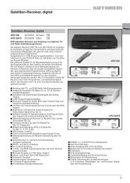
Photo on title page: Train antennas in the past <strong>and</strong> now (high-speed maglev train in Shanghai).<br />
Catalogue Issue 11/2006<br />
All data published in previous catalog issues hereby becomes invalid.<br />
We reserve the right to make alterations in accordance with the requirements of our customers.<br />
Please note:<br />
The details given in our data sheets have to be<br />
followed carefully when installing the antennas <strong>and</strong><br />
accessories.<br />
The installation team must be properly qualified<br />
<strong>and</strong> also be familiar with the relevant national safety<br />
regulations.<br />
“Quality leads the way”<br />
As the world’s oldest <strong>and</strong> largest antenna manufacturer, we live up to claim “Quality<br />
leads the way” on a daily basis. One of the fundamental principies is to always be on<br />
the lookout <strong>for</strong> the best solution <strong>for</strong> our customers.<br />
Our quality assurance system <strong>and</strong> our environmental management system apply to the<br />
entire company <strong>and</strong> are certified by TÜV according to EN ISO 9001 <strong>and</strong> EN ISO 14001.<br />
KATHREIN-Werke KG . Telephone +49 8031 184-0 . Fax +49 8031 184-973<br />
Anton-<strong>Kathrein</strong>-Straße 1 – 3 . P.O. Box 10 04 44 . D-83004 Rosenheim . Internet: www.kathrein.de<br />
Germany
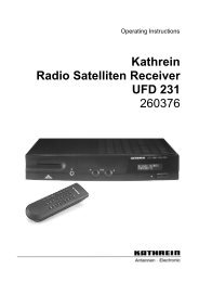
Munich city tram<br />
3
Summary<br />
<strong>Antennas</strong> <strong>for</strong> trains <strong>and</strong> buses<br />
68 ... 2700 MHz<br />
4<br />
Frequency b<strong>and</strong> Type No.<br />
4m-b<strong>and</strong> K 50 21 41<br />
Tunable in the range<br />
68 ... 87.5 MHz<br />
Yes 6<br />
FM radio 727 313 87.5 – 108 MHz Yes Only <strong>for</strong> receiving 7<br />
2m-b<strong>and</strong><br />
K 50 21 22<br />
2m-/70cm-b<strong>and</strong> 731 495<br />
70cm-b<strong>and</strong><br />
70cm-b<strong>and</strong><br />
800/900 MHz<br />
900 MHz<br />
800/900/1800 MHz /<br />
UMTS / WLAN / WIMAX<br />
Tunable in the range<br />
146 ... 174 MHz<br />
K 50 22 21 . 146 – 156 MHz<br />
K 50 22 22 . 156 – 174 MHz<br />
Yes Low profile 8<br />
Low profile 9<br />
733 707 146 – 172 MHz Yes 10<br />
165 – 174 MHz<br />
457.4 – 468.3 MHz<br />
Two-b<strong>and</strong> antenna 11<br />
870 10008 380 – 430 MHz Yes 12<br />
K 70 23 2. . 406 ... 470 MHz Low profile 13<br />
K 70 20 21 410 – 470 MHz Yes 14<br />
725 892 410 – 430 MHz<br />
K 70 21 21 450 – 470 MHz<br />
Yes Gain 2 dB 15<br />
729 003 444 – 461.5 MHz Special radome 16<br />
721 232 457 – 470 MHz Special radome 16<br />
K 70 20 61<br />
870 10009<br />
Operating Type approved by<br />
frequency range “Deutsche Bahn AG”<br />
450 – 470 MHz<br />
806 – 960 MHz<br />
430 – 470 MHz<br />
870 – 960 MHz<br />
Remarks Page<br />
Yes Two-b<strong>and</strong> antenna 17<br />
Yes Two-b<strong>and</strong> antenna 18<br />
741 009 870 – 960 MHz Yes Special radome 19<br />
K 70 21 63 1 876 – 960 MHz Yes Gain 3.5 dB 20<br />
870 10007 806 – 2700 MHz Yes Low profile 21<br />
<strong>Antennas</strong> with integrated GPS-Module<br />
70cm-b<strong>and</strong> / 380 – 430 MHz<br />
870 10005<br />
GPS<br />
1575.42 ± 1 MHz<br />
Installation Guidelines see from page 26 onwards<br />
Yes 22<br />
70cm-b<strong>and</strong> / 430 – 470 MHz<br />
900 MHz / 870 10006 870 – 960 MHz Yes 23<br />
GPS 1575.42 ± 1 MHz<br />
800/900/1800 MHz /<br />
UMTS / WLAN / 870 10003<br />
WIMAX / GPS<br />
new<br />
new<br />
new<br />
new<br />
new<br />
new<br />
new<br />
806 – 2700 MHz<br />
1575.42 ± 1 MHz<br />
Yes Low profile 24<br />
GPS 860 10069 1575.42 ± 1 MHz Low noise amplifier 25<br />
Additional antenna types available on request. Please contact:<br />
antennas.mobilcom@kathrein.de
Article summary<br />
The articles are listed by type number<br />
in numerical order<br />
Multi-b<strong>and</strong> Combiners<br />
Type No. Page<br />
721 232 16<br />
725 892 15<br />
727 313 7<br />
728 954 17<br />
729 003 16<br />
731 495 11<br />
733 707 10<br />
741 009 18<br />
790 244 11<br />
860 10069 25<br />
870 10003 24<br />
870 10005 22<br />
870 10006 23<br />
870 10007 21<br />
870 10008 12<br />
870 10009 18<br />
For multi-b<strong>and</strong> antennas, several combiners <strong>for</strong><br />
combining the b<strong>and</strong>s are available. All devices<br />
undergo vibration- und shock tests according to<br />
ETS-300019-1-4.<br />
Separate catalogues <strong>and</strong> our homepage<br />
provide in<strong>for</strong>mation <strong>for</strong> the<br />
combiners. Of course any question may also be<br />
directly put to antennas.mobilcom@kathrein.de.<br />
Type No. Page<br />
K 50 21 41 6<br />
K 50 21 22 8<br />
K 50 22 21 1 9<br />
K 50 22 21 2 9<br />
K 50 22 22 1 9<br />
K 50 22 22 2 9<br />
K 70 20 21 14<br />
K 70 20 61 17<br />
K 70 21 21 15<br />
K 70 21 63 1 19<br />
K 70 23 21 13<br />
K 70 23 21 0 13<br />
K 70 23 21 1 13<br />
K 70 23 23 13<br />
K 70 23 23 0 13<br />
K 70 23 23 1 13<br />
Triple-b<strong>and</strong> Combiner GSM-R/GSM 900 – GSM 1800 – UMTS<br />
5
Train Antenna<br />
68 ... 87.5 MHz<br />
K 50 21 41<br />
• Aluminum antenna in fiberglass radome.<br />
• Fully tunable in the 68 ... 87.5 MHz range.<br />
6<br />
Type No. K 50 21 41<br />
Input N female<br />
Frequency range 68 ... 87.5 MHz<br />
Impedance 50 Ω<br />
Polarization Vertical<br />
Max. power 100 W (at 50 °C ambient temperature)<br />
Weight 5.3 kg<br />
Packing size (outside) 502 x 162 x 370 mm<br />
Material: Radiator <strong>and</strong> base: Aluminum.<br />
Radome: Fiberglass; Colour: Grey.<br />
Mounting: On a conductive surface 200 x 100 cm min. with<br />
3 studs M10.<br />
Tuning: The antenna can be tuned to the transmitter<br />
frequency in the range 68 ... 87.5 MHz by two<br />
tuning screws.<br />
Grounding <strong>and</strong> This antenna approved by the “Deutsche<br />
high voltage protection: Bahn AG” is D.C. grounded to protect against<br />
lightning <strong>and</strong> high-tension lines.<br />
Special features: After mounting the antenna can be turned ± 30°<br />
when the mounting elements are still loose. The<br />
tuning screws are inside the fiberglass cover <strong>and</strong><br />
easily accessible from the outside by means of<br />
plastic caps.<br />
Scope of supply: Antenna <strong>and</strong> watertight ring (O-seal).<br />
Typical St<strong>and</strong>ing Wave Ratio (VSWR)<br />
Examples <strong>for</strong> tuning to different frequencies measured<br />
against a 2 x 1 m conductive plane.<br />
43 mm<br />
M10<br />
20 mm<br />
120<br />
mm<br />
Welding flange:<br />
324 mm<br />
≈ 478 mm ≈<br />
35 mm<br />
±30°<br />
Parallel to the tracks<br />
144 mm<br />
watertight ring<br />
(O-seal)<br />
evenness < 0.2 mm
Train Antenna<br />
87.5 – 108 MHz<br />
727 313<br />
• FM-broadcast receiving antenna <strong>for</strong> rail vehicles in fiberglass<br />
radome.<br />
• Only <strong>for</strong> receiving.<br />
Type No. 727 313<br />
Input N female<br />
Frequency range 87.5 – 108 MHz<br />
Impedance 50 Ω<br />
Polarization Vertical<br />
Weight 0.9 kg<br />
Packing size (outside) 151 x 90 x 415 mm<br />
Material: Flange: Aluminum.<br />
Radiator: Copper.<br />
Radome: Fiberglass; Colour: Light grey.<br />
All screws <strong>and</strong> nuts: Stainless steel.<br />
Mounting: On a conductive surface with a minimum size of<br />
100 x 200 cm by means of existing M10 studs.<br />
Grounding <strong>and</strong> This antenna approved by the “Deutsche<br />
high voltage protection: Bahn AG” is D.C. grounded to protect against<br />
lightning <strong>and</strong> high-tension lines.<br />
Mounting flange:<br />
80 mm<br />
nicht lackiert<br />
not painted<br />
32 mm<br />
Dichtungsring<br />
Sealing O-ring<br />
145 mm<br />
115 mm<br />
13<br />
mm<br />
43 mm<br />
Mounting hole <strong>for</strong> the connector: 33 (max. 35) mm diameter.<br />
Note: Keep mounting surface clear of paint <strong>for</strong> electrical contact.<br />
28 mm<br />
nicht lackiert<br />
not painted<br />
56 mm<br />
355 mm<br />
7
Low Silhouette Train Antenna<br />
146 ... 174 MHz<br />
K 50 21 22<br />
• Tunable antenna.<br />
• Hot dip galvanized steel.<br />
8<br />
Type No. K 50 21 22<br />
Input UHF female<br />
Frequency range 146 ... 174 MHz<br />
Impedance 50 Ω<br />
Antenna efficiency > 0.95<br />
Polarization Vertical<br />
Max. power 100 W (at 50 °C ambient temperature)<br />
Weight 3.3 kg<br />
Packing size (outside) 232 x 172 x 305 mm<br />
Material: Radiator <strong>and</strong> base: Hot dip galvanized steel.<br />
Tuning screws: Brass, nickel plated.<br />
Colour: Unpainted zinc surface.<br />
Mounting: On a conductive surface 100 x 100 cm min. with<br />
4 studs M10 <strong>and</strong> counterflange.<br />
Tuning: With two tuning screws the antenna can be set<br />
to the transmitter frequency.<br />
Grounding <strong>and</strong> This antenna approved by the “Deutsche<br />
high voltage protection: Bahn AG” is D.C. grounded to protect against<br />
lightning <strong>and</strong> high-tension lines.<br />
Scope of supply: Antenna with 4 studs, each with 2 nuts, 1 rubber<br />
gasket <strong>and</strong> 1 counterflange.<br />
9 mm<br />
215 mm<br />
80 mm<br />
140 mm<br />
145 mm
Train Antenna<br />
146 ... 174 MHz<br />
K 50 22 2. .<br />
• Broadb<strong>and</strong> antenna in fiberglass radome.<br />
Type No. K 50 22 21 1 K 50 22 21 2<br />
Input N female UHF female<br />
Frequency range 146 – 156 MHz<br />
VSWR < 1.4<br />
Impedance 50 Ohm<br />
Polarization Vertical<br />
Max. power 100 W (at 50° C ambient temperature)<br />
Weight 1.2 kg<br />
Packing size (outside) 262 x 262 x 145 mm<br />
Type No. K 50 22 22 1 K 50 22 22 2<br />
Input N female UHF female<br />
Frequency range 156 – 174 MHz<br />
VSWR < 1.4<br />
Impedance 50 Ohm<br />
Polarization Vertical<br />
Max. power 100 Watt (at 50° C ambient temperature)<br />
Weight 1.2 kg<br />
Packing size (outside) 262 x 262 x 145 mm<br />
Material: Radiator <strong>and</strong> Base: Aluminum.<br />
Radome: Fiberglass, colour: Grey.<br />
Studs <strong>and</strong> all screws <strong>and</strong> nuts: Stainless steel.<br />
Mounting: On a conductive surface 100 x 100 cm min. with<br />
3 studs M10 <strong>and</strong> counterflange.<br />
Note: No superstructures in this area.<br />
Grounding <strong>and</strong> D.C. grounded to protect against lightning <strong>and</strong><br />
high voltage protection: high-tension lines.<br />
Scope of supply: Antenna with 3 studs, each with 2 nuts, 1 rubber<br />
gasket <strong>and</strong> 1 counterflange.<br />
120 mm<br />
Driving direction<br />
230 mm<br />
246 mm<br />
9
Train Antenna<br />
146 – 172 MHz<br />
733 707<br />
• Aluminum antenna in fiberglass radome.<br />
Type No. 733 707<br />
Input N female<br />
Frequency range 146 – 172 MHz<br />
VSWR < 2.0<br />
Gain 0 dB (ref. to the quarter-wave antenna)<br />
Impedance 50 Ω<br />
Polarization Vertical<br />
Max. power 100 W (at 50 °C ambient temperature)<br />
Weight 0.8 kg<br />
Packing size (outside) 151 x 90 x 415 mm<br />
Material: Radiator <strong>and</strong> Flange: Aluminum.<br />
Radome: Fiberglass, colour: Light grey.<br />
All screws <strong>and</strong> nuts: Stainless steel.<br />
Mounting: On a conductive surface 100 x 100 cm min.<br />
with 4 studs M10.<br />
Grounding <strong>and</strong> This antenna approved by the “Deutsche<br />
high voltage protection: Bahn AG” is D.C. grounded to protect against<br />
lightning <strong>and</strong> high-tension lines.<br />
Mounting flange:<br />
80 mm<br />
Mounting hole <strong>for</strong> the connector: 33 (max. 35) mm diameter.<br />
Note: Keep mounting surface clear of paint <strong>for</strong> electrical contact.<br />
10<br />
nicht lackiert<br />
not painted<br />
32 mm<br />
Dichtungsring<br />
Sealing O-ring<br />
145 mm<br />
115 mm<br />
13<br />
mm<br />
43 mm<br />
28 mm<br />
nicht lackiert<br />
not painted<br />
56 mm<br />
355 mm
Train Antenna<br />
165 – 174 MHz <strong>and</strong> 457.4 – 468.3 MHz<br />
731 495<br />
• Two-b<strong>and</strong> antenna in fiberglass radome.<br />
• The antenna can be operated in both frequency ranges<br />
simultaneously by using the combiner 790 244.<br />
Type No. 731 495<br />
Input N female<br />
Frequency range 165 – 174MHz 457.4 – 468.3 MHz<br />
VSWR < 1.6<br />
Gain 0 dB 2 dB<br />
(ref. to the quarter-wave antenna)<br />
Impedance 50 Ω<br />
Polarization Vertical<br />
Max. power 10 W (at 50 °C ambient temperature)<br />
Weight 0.8 kg<br />
Packing size (outside) 151 x 90 x 415 mm<br />
Material: Radiator <strong>and</strong> flange: Aluminum.<br />
Radome: Fiberglass; Colour: Light grey.<br />
All screws <strong>and</strong> nuts: Stainless steel.<br />
Mounting: On a conductive surface 100 x 100 cm min. with<br />
4 studs M10.<br />
Grounding <strong>and</strong> This antenna is D.C. grounded to protect against<br />
high voltage protection: lightning <strong>and</strong> high-tension lines.<br />
Accessories: Combiner (order separately)<br />
Type No. 790 244<br />
Input 3 x N female<br />
Frequency range:<br />
4 m- <strong>and</strong> 2 m-b<strong>and</strong> 68 – 174 MHz<br />
70 cm-b<strong>and</strong> 400 – 470 MHz<br />
Impedance 50 Ω<br />
Insertion loss < 0.5 dB<br />
Coupling loss > 35 dB<br />
Mounting flange:<br />
145 mm<br />
56 mm<br />
32 mm<br />
80 mm<br />
28 mm<br />
13<br />
mm<br />
Dichtungsring<br />
Sealing O-ring<br />
43 mm<br />
355 mm<br />
nicht lackiert<br />
not painted<br />
nicht lackiert<br />
not painted<br />
Mounting hole <strong>for</strong> the connector:<br />
33 (max. 35) mm diameter.<br />
Note: Keep mounting surface clear of paint<br />
<strong>for</strong> electrical contact.<br />
115 mm<br />
11
Train Antenna<br />
380 – 430 MHz<br />
870 10008<br />
• Low profile antenna in fiberglass radome.<br />
• The antenna fulfils the requirements according to EN 50155.<br />
Type No. 870 10008<br />
Antenna<br />
Input N female<br />
Frequency range 380 – 430 MHz<br />
VSWR < 1.7<br />
Gain 0 dB (ref. to the quarter-wave antenna)<br />
Impedance 50 Ω<br />
Polarization Vertical<br />
Max. power 100 W (at 50° C ambient temperature)<br />
Inner conductor D.C. grounded<br />
Weight Approx. 0.5 kg<br />
Packing size, L x W x H 150 x 90 x 190 mm<br />
Height 150 mm<br />
Material: Radiator: Copper <strong>and</strong> brass.<br />
Flange: Aluminum. Radome: Fiberglass.<br />
All screws <strong>and</strong> nuts: Stainless steel.<br />
Colour: Grey.<br />
Mounting: On a conductive surface with a minimum size<br />
of 1000 x 1000 mm by cap nut only on 4 existing<br />
M10 studs.<br />
Grounding <strong>and</strong> This antenna, tested by an independent institute<br />
high voltage protection: <strong>and</strong> approved by the “Deutsche Bahn AG”, is<br />
D.C. grounded to protect against lightning <strong>and</strong><br />
high-tension lines.<br />
12<br />
Mounting flange:<br />
145<br />
115<br />
43<br />
32<br />
85<br />
56<br />
82<br />
contact area<br />
seal<br />
Input Antenna<br />
400 MHz<br />
11 mm diameter<br />
contact area<br />
Mounting hole <strong>for</strong> the connector: 33 mm (max. 35 mm)<br />
Note: Mounting surface must be free from paint <strong>for</strong><br />
electrical contact.<br />
Evenness of opposite surface 0.2 mm.<br />
Use a cap nut plus the enclosed sealing washer.<br />
Added sealing<br />
washer<br />
Cap nut M10 DIN 1587<br />
torque 15 Nm – 20 Nm<br />
15<br />
Situation of mounting<br />
150<br />
142
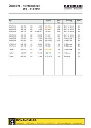
Vehicular antenna<br />
406 ... 470 MHz<br />
K 70 23 21 ., K 70 23 23 .<br />
Frequency range 406 – 428 MHz<br />
Typ Nr. K 70 23 21 0 K 70 23 21 K 70 23 21 1<br />
Input M 11 x 1 female M 11 x 1 female N-female<br />
(the connector <strong>for</strong> cable (the connector <strong>for</strong> cable<br />
RG 58 C/U is supplied). RG 213/U is supplied).<br />
Drill hole dimension 12 mm 12 mm 17 mm<br />
Frequency range 406 – 428 MHz<br />
VSWR < 1.7<br />
Gain 0 dB (ref. to the quarter-wave antenna)<br />
Impedance 50 Ω<br />
Polarization Vertical<br />
Max. power 50 W (at 50 °C ambient temperature)<br />
Weight 0.40 kg<br />
Packing size<br />
(outside) 117 x 117 x 114 mm<br />
Height 70 mm<br />
Frequency range 440 – 470 MHz<br />
Typ Nr. K 70 23 23 0 K 70 23 23 K 70 23 23 1<br />
Input M 11 x 1 female M 11 x 1 female N-female<br />
(the connector <strong>for</strong> cable (the connector <strong>for</strong> cable<br />
RG 58 C/U is supplied). RG 213/U is supplied).<br />
Drill hole dimension 12 mm 12 mm 17 mm<br />
Frequency range 440 – 470 MHz<br />
VSWR < 1.5<br />
Gain 0 dB (ref. to the quarter-wave antenna)<br />
Impedance 50 Ω<br />
Polarisation Vertical<br />
Max. power 50 Watt (at 50 °C ambient temperature)<br />
Weight 0.40 kg<br />
Packing size<br />
(outside) 117 x 117 x 114 mm<br />
Height 70 mm<br />
Material: Radiator <strong>and</strong> base: Aluminum.<br />
Radome: High impact plastic.<br />
All screws an nuts: Stainless steel.<br />
Mounting: On a conductive surface 50 x 50 cm min.<br />
The drilling diameter is 12 mm except the N connector versions: 17 mm.<br />
A special zinc washer ensures a good contact at the edges of the hole.<br />
Special features: All metall parts of this antenna are D.C. grounded.<br />
Extreme robust <strong>and</strong> car-wash proof vehicular antenna.<br />
100 mm<br />
110 mm<br />
70 mm<br />
25 mm<br />
13
Train Antenna<br />
410 – 470 MHz<br />
K 70 20 21<br />
• Low profile broadb<strong>and</strong> antenna in fiberglass radome.<br />
Type No. K 70 20 21<br />
Input N-female<br />
Frequency range 410 – 470 MHz<br />
VSWR < 1.5<br />
Gain 0 dB (ref. to the quarter-wave antenna)<br />
Impedance 50 Ohm<br />
Polarization Vertical<br />
Max. power 170 W (at 50° C ambient temperature)<br />
Weight 0.5 kg<br />
Packing size (outside) 151 x 87 x 210 mm<br />
Material: Radiator <strong>and</strong> Flange: Aluminum.<br />
Radome: Fiberglass, colour: Light grey.<br />
All screws <strong>and</strong> nuts: Stainless steel.<br />
Mounting: On a conductive surface with a minimum size of<br />
50 x 50 cm by means of existing M10 studs.<br />
Grounding <strong>and</strong> This antenna approved by the “Deutsche<br />
high voltage protection: Bahn AG” is D.C. grounded to protect against<br />
lightning <strong>and</strong> high-tension lines.<br />
Mounting flange:<br />
80 mm<br />
Mounting hole <strong>for</strong> the connector: 33 (max. 35) mm diameter.<br />
Note: Keep mounting surface clear of paint <strong>for</strong> electrical contact.<br />
14<br />
nicht lackiert<br />
not painted<br />
32 mm<br />
Dichtungsring<br />
Sealing O-ring<br />
145 mm<br />
115 mm<br />
13<br />
mm<br />
43 mm<br />
28 mm<br />
nicht lackiert<br />
not painted<br />
56 mm<br />
142 mm
Train Antenna<br />
410 – 430 / 450 – 470 MHz<br />
K 70 21 21, 725 892<br />
• 2 dB gain broadb<strong>and</strong> antenna in fiberglas radome.<br />
Type No. K 70 21 21 725 892<br />
Input N-female<br />
Frequency range 450 – 470 MHz 410 – 430 MHz<br />
VSWR < 1.5<br />
Gain 2 dB (ref. to the quarter-wave antenna)<br />
Impedance 50 Ohm<br />
Polarization Vertical<br />
Max. power 640 W (at 50° C ambient temperature)<br />
Weight 0.8 kg<br />
Packing size (outside) 151 x 90 x 415 mm<br />
Material: Radiator <strong>and</strong> Flange: Aluminum.<br />
Radome: Fiberglass, colour: Light grey.<br />
All screws <strong>and</strong> nuts: Stainless steel.<br />
Mounting: On a conductive surface with a minimum size of<br />
50 x 50 cm by means of existing M10 studs.<br />
Grounding <strong>and</strong> This antenna approved by the “Deutsche<br />
high voltage protection: Bahn AG” is D.C. grounded to protect against<br />
lightning <strong>and</strong> high-tension lines.<br />
Mounting flange:<br />
80 mm<br />
nicht lackiert<br />
not painted<br />
32 mm<br />
Dichtungsring<br />
Sealing O-ring<br />
145 mm<br />
115 mm<br />
13<br />
mm<br />
43 mm<br />
Mounting hole <strong>for</strong> the connector: 33 (max. 35) mm diameter.<br />
Note: Keep mounting surface clear of paint <strong>for</strong> electrical contact.<br />
28 mm<br />
nicht lackiert<br />
not painted<br />
56 mm<br />
355 mm<br />
15
Low Silhouette Train Antenna<br />
444 ... 470 MHz<br />
729 003, 721 232<br />
• 0 dB antenna of very low profile in fiberglass radome.<br />
Type No. 729 003 721 232<br />
Input N female N female<br />
Frequency range 444 – 461.5 MHz 457 – 470 MHz<br />
VSWR < 1.7 (444 – 461.5 MHz) < 1.5<br />
< 1.5 (448 – 458 MHz) .<br />
Gain 0 dB (ref. to the quarter-wave antenna)<br />
Impedance 50 Ω<br />
Polarization Vertical<br />
Max. power 50 W (at 50 °C ambient temperature)<br />
Weight 0.65 kg<br />
Packing size (outside) 137 x 92 x 174 mm<br />
Material: Base: Aluminum.<br />
Radiator: Aluminum.<br />
Radome: Fiberglass; Colour: Grey.<br />
All screws <strong>and</strong> nuts: Stainless steel.<br />
Mounting: On a conductive surface of a minimum size of<br />
50 x 50 cm by means of 4 existing M10 studs.<br />
Grounding <strong>and</strong> This antenna is D.C. grounded to protect against<br />
high voltage protection: lightning <strong>and</strong> high-tension lines.<br />
Mounting flange:<br />
82 mm<br />
16<br />
nicht lackiert<br />
not painted<br />
32 mm<br />
Dichtungsring<br />
Sealing O-ring<br />
145 mm<br />
115 mm<br />
13<br />
mm<br />
43 mm<br />
Mounting hole <strong>for</strong> the connector: 33 (max. 35) mm diameter.<br />
Note: Keep mounting surface clear of paint <strong>for</strong> electrical contact.<br />
28 mm<br />
nicht lackiert<br />
not painted<br />
56 mm<br />
163 mm<br />
95 mm
Train Antenna<br />
450 – 470 MHz <strong>and</strong> 806 – 960 MHz<br />
K 70 20 61<br />
• Two-b<strong>and</strong> antenna in fiberglass radome working in the<br />
450 – 470 MHz <strong>and</strong> 806 – 960 MHz range.<br />
• The antenna can be operated in both frequency ranges<br />
simultaneously by using the combiner 728 954.<br />
Type No. K 70 20 61<br />
Input N female<br />
Frequency range 450 – 470 MHz <strong>and</strong> 806 – 960 MHz<br />
VSWR < 1.5<br />
Gain 0 dB (ref. to the quarter-wave antenna)<br />
Impedance 50 Ω<br />
Polarization Vertical<br />
Max. power 500 W (at 50 °C ambient temperature)<br />
Weight 0.5 kg<br />
Packing size (outside) 151 x 87 x 210 mm<br />
Material: Radiator: Brass.<br />
Flange: Aluminum.<br />
Radome: Fiberglass; Colour: Light grey.<br />
All screws <strong>and</strong> nuts: Stainless steel.<br />
Mounting: On a conductive surface with a minimum size of<br />
50 x 50 cm by means of 4 existing M10 studs.<br />
Grounding <strong>and</strong> This antenna approved by the “Deutsche<br />
high voltage protection: Bahn AG” is D.C. grounded to protect against<br />
lightning <strong>and</strong> high-tension lines.<br />
Accessories: Combiner (order separately)<br />
Type No. 728 954<br />
Input 3 x N female<br />
Frequency range: 50 – 1000 MHz<br />
Input 1 50 – 470 MHz<br />
Input 2 870 – 1000 MHz<br />
Impedance 50 Ω<br />
Insertion loss < 0.5 dB<br />
Input 1 → Output < 0.4 dB (typ. 0.3 dB)<br />
Input 2 → Output < 0.5 dB (typ. 0.4 dB)<br />
Coupling loss<br />
Input 1 ↔ Input 2 > 45 dB<br />
Mounting flange:<br />
145 mm<br />
56 mm<br />
32 mm<br />
80 mm<br />
28 mm<br />
13<br />
mm<br />
Dichtungsring<br />
Sealing O-ring<br />
nicht lackiert<br />
not painted<br />
43 mm<br />
nicht lackiert<br />
not painted<br />
Mounting hole <strong>for</strong> the connector:<br />
33 (max. 35) mm diameter.<br />
Note: Keep mounting surface clear of paint<br />
<strong>for</strong> electrical contact.<br />
115 mm<br />
142 mm<br />
17
Train Antenna<br />
430 – 470 MHz <strong>and</strong> 870 – 960 MHz<br />
870 10009<br />
• Two-b<strong>and</strong> Antenna: 430 – 470 MHz / 870 – 960 MHz<br />
• Low profile antenna in fiberglass radome.<br />
• The antenna fulfils the requirements according to EN 50155.<br />
Type No. 870 10009<br />
Antenna two-b<strong>and</strong><br />
Input N female<br />
Frequency range 430 – 470 MHz<br />
870 – 960 MHz<br />
VSWR < 1.5<br />
Gain 0 dB (ref. to the quarter-wave antenna)<br />
Impedance 50 Ω<br />
Polarization Vertical<br />
Max. power 100 W (at 50° C ambient temperature)<br />
Inner conductor D.C. grounded<br />
Weight Approx. 0.5 kg<br />
Packing size, L x W x H 150 x 90 x 190 mm<br />
Height 150 mm<br />
Material: Radiator: Copper <strong>and</strong> brass.<br />
Flange: Aluminum. Radome: Fiberglass.<br />
All screws <strong>and</strong> nuts: Stainless steel.<br />
Colour: Grey.<br />
Mounting: On a conductive surface with a minimum size<br />
of 1000 mm x 1000 mm by cap nut only on 4<br />
existing M10 studs.<br />
Grounding <strong>and</strong> This antenna, tested by an independent institute<br />
high voltage protection: <strong>and</strong> approved by the “Deutsche Bahn AG”, is<br />
D.C. grounded to protect against lightning <strong>and</strong><br />
high-tension lines.<br />
18<br />
Mounting flange:<br />
145<br />
115<br />
43<br />
32<br />
85<br />
56<br />
82<br />
contact area<br />
seal<br />
Input Antenna<br />
450 MHz /<br />
900 MHz<br />
11 mm diameter<br />
contact area<br />
Mounting hole <strong>for</strong> the connector: 33 mm (max. 35 mm)<br />
Note: Mounting surface must be free from paint <strong>for</strong><br />
electrical contact.<br />
Evenness of opposite surface 0.2 mm.<br />
Use a cap nut plus the enclosed sealing washer.<br />
Added sealing<br />
washer<br />
Cap nut M10 DIN 1587<br />
torque 15 Nm – 20 Nm<br />
15<br />
Situation of mounting<br />
150<br />
142
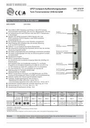
Train Antenna<br />
870 – 960 MHz<br />
741 009<br />
• Broadb<strong>and</strong> antenna of very low profile in fiberglass radome.<br />
Typ Nr. 741 009<br />
Input N-female<br />
Frequency range 870 – 960 MHz<br />
VSWR < 1.5<br />
Gain 0 dB (ref. to the quarter-wave antenna)<br />
Impedance 50 Ω<br />
Polarization Vertical<br />
Max. power 100 W (at 50 °C ambient temperature)<br />
Weight 0.5 kg<br />
Packing size (outside) 137 x 92 x 174 mm<br />
Material: Radiator: Brass.<br />
Flange: Aluminum.<br />
Radome: Fiberglass; Colour: Light grey.<br />
All screws <strong>and</strong> nuts: Stainless steel.<br />
Mounting: On a conductive surface of a minimum size of<br />
50 x 50 cm by means of 4 existing M10 studs.<br />
Grounding <strong>and</strong> This antenna approved by the “Deutsche<br />
high voltage protection: Bahn AG” is D.C. grounded to protect against<br />
lightning <strong>and</strong> high-tension lines.<br />
Mounting flange:<br />
82 mm<br />
nicht lackiert<br />
not painted<br />
32 mm<br />
Dichtungsring<br />
Sealing O-ring<br />
145 mm<br />
115 mm<br />
13<br />
mm<br />
43 mm<br />
Mounting hole <strong>for</strong> the connector: 33 (max. 35) mm diameter.<br />
Note: Keep mounting surface clear of paint <strong>for</strong> electrical contact.<br />
28 mm<br />
nicht lackiert<br />
not painted<br />
56 mm<br />
163 mm<br />
95 mm<br />
19
Train Antenna<br />
876 – 960 MHz<br />
K 70 21 63 1<br />
• Broadb<strong>and</strong> gain antenna in fiberglass radome.<br />
Type No. K 70 21 63 1<br />
Input N female<br />
Frequency range 876 – 960 MHz<br />
VSWR < 1.5<br />
Gain 3.5 dB (ref. to the quarter-wave antenna)<br />
Impedance 50 Ω<br />
Polarization Vertical<br />
Max. power 500 W (at 50 °C ambient temperature)<br />
Weight 1 kg<br />
Packing size (outside) 151 x 90 x 415 mm<br />
Material: Radiator: Brass.<br />
Flange: Aluminum.<br />
Radome: Fiberglass; Colour: Light grey.<br />
All screws <strong>and</strong> nuts: Stainless steel.<br />
Mounting: On a conductive surface with a minimum size of<br />
50 x 50 cm by means of 4 existing M10 studs.<br />
Grounding <strong>and</strong> This antenna approved by the “Deutsche<br />
high voltage protection: Bahn AG” is D.C. grounded to protect against<br />
lightning <strong>and</strong> high-tension lines.<br />
Mounting flange:<br />
80 mm<br />
Mounting hole <strong>for</strong> the connector: 33 (max. 35) mm diameter.<br />
Note: Keep mounting surface clear of paint <strong>for</strong> electrical contact.<br />
20<br />
nicht lackiert<br />
not painted<br />
32 mm<br />
Dichtungsring<br />
Sealing O-ring<br />
145 mm<br />
115 mm<br />
13<br />
mm<br />
43 mm<br />
28 mm<br />
nicht lackiert<br />
not painted<br />
56 mm<br />
355 mm
Train Antenna<br />
806 – 2700 MHz<br />
870 10007<br />
• Multi-b<strong>and</strong> antenna: 800/900/1800/1900/UMTS/UMTS II/W-LAN.<br />
• The antenna can be operated in all frequency ranges<br />
simultaneously.<br />
• Low profile antenna in fiberglass radome.<br />
• The antenna fulfils the requirements according to EN 50155.<br />
Type No. 870 10007<br />
Antenna multi-b<strong>and</strong><br />
Input N female<br />
Frequency range 806 – 2700 MHz<br />
VSWR 806 – 870 MHz: < 2.0<br />
870 – 2550 MHz: < 1.5<br />
2550 – 2700 MHz: < 2.0<br />
Gain 0 dB (ref. to the quarter-wave antenna)<br />
Impedance 50 Ω<br />
Polarization Vertical<br />
Max. power 100 W (at 50° C ambient temperature)<br />
Inner conductor D.C. grounded<br />
Weight approx. 0.5 kg<br />
Packing size 152 x 91 x 125 mm<br />
Hight 81 mm<br />
Material: Radiator: Copper <strong>and</strong> brass.<br />
Flange: Aluminum. Radome: Fiberglass.<br />
All screws <strong>and</strong> nuts: Stainless steel.<br />
Colour: Grey.<br />
Mounting: On a conductive surface with a minimum size<br />
of 1000 x 1000 mm by cap nut only on 4 existing<br />
M10 studs.<br />
Grounding <strong>and</strong> This antenna, tested by an independent institute<br />
high voltage protection: <strong>and</strong> approved by the “Deutsche Bahn AG”, is<br />
D.C. grounded to protect against lightning <strong>and</strong><br />
high-tension lines.<br />
Mounting flange:<br />
145<br />
115<br />
43<br />
32<br />
85<br />
56<br />
82<br />
contact area<br />
seal<br />
Input Antenna<br />
870 / 2500 MHz<br />
11 mm diameter<br />
81<br />
contact area<br />
Mounting hole <strong>for</strong> the connector: 33 mm (max. 35 mm)<br />
Note: Mounting surface must be free from paint <strong>for</strong><br />
electrical contact.<br />
Evenness of opposite surface 0.2 mm.<br />
Use a cap nut plus the enclosed sealing washer.<br />
Added sealing<br />
washer<br />
Cap nut M10 DIN 1587<br />
torque 15 Nm – 20 Nm<br />
15<br />
Situation of mounting<br />
142<br />
21
Train Antenna<br />
380 – 430 MHz <strong>and</strong> GPS 1575 MHz<br />
870 10005<br />
• Two-b<strong>and</strong> antenna: 380 – 430 MHz <strong>and</strong> GPS.<br />
• The antenna can be operated in both frequency ranges<br />
simultaneously.<br />
• Low profile antenna in fiberglass radome.<br />
• The antenna fulfils the requirements according to EN 50155.<br />
Type No. 870 10005<br />
Antenna 380 – 430 MHz<br />
Input N female<br />
Frequency range 380 – 430 MHz<br />
VSWR < 1.7<br />
Gain 0 dB (ref. to the quarter-wave antenna)<br />
Impedance 50 Ω<br />
Polarization Vertical<br />
Max. power 100 W (at 50° C ambient temperature)<br />
Inner conductor D.C. grounded<br />
Antenna GPS<br />
Input Cable RG 316/U of 225 mm length<br />
with TNC male connector<br />
Frequency range 1575.42 ±1 MHz<br />
VSWR < 1.5<br />
Polarization Right h<strong>and</strong> circular<br />
Gain (90° elevation) 2 dB (ref. to the circularly polarized<br />
isotropic antenna)<br />
Impedance 50 Ω<br />
Inner conductor D.C. grounded<br />
Weight Approx. 0.5 kg<br />
Packing size 150 x 90 x 190 mm<br />
Height 150 mm<br />
Material: Radiator: Copper <strong>and</strong> brass.<br />
Flange: Aluminum. Radome: Fiberglass.<br />
All screws <strong>and</strong> nuts: Stainless steel.<br />
Colour: Grey.<br />
Mounting: On a conductive surface with a minimum size<br />
of 1000 x 1000 mm by cap nut only on 4 existing<br />
M10 studs.<br />
Grounding <strong>and</strong> This antenna, tested by an independent institute<br />
high voltage protection: <strong>and</strong> approved by the “Deutsche Bahn AG”, is<br />
D.C. grounded to protect against lightning <strong>and</strong><br />
high-tension lines.<br />
Accessories: Low noise amplifier GPS 860 10069 (please<br />
order separately).<br />
Warning: If the antenna is operated without the preamplifier<br />
type no. 860 10069, please note the<br />
following points.<br />
– Due to the fact that the inner conductor of the<br />
antenna GPS is DC grounded, the input of the<br />
GPS receiver is loaded with a DC short circuit.<br />
If the GPS receiver provides a remote DC<br />
power supply, this could damage the GPS<br />
receiver.<br />
– At the input of the antenna GPS a level of<br />
–25 dB below the signal applied at the input<br />
of the antenna 380 – 430 MHz appears.<br />
Depending on the level of the signal applied at<br />
the input of the antenna 380 – 430 MHz, the<br />
GPS receiver may be overloaded or damaged.<br />
22<br />
Mounting flange:<br />
145<br />
115<br />
43<br />
32<br />
85<br />
56<br />
82<br />
contact area<br />
seal<br />
Input Antenna<br />
GPS<br />
Input Antenna<br />
400 MHz<br />
11 mm diameter<br />
contact area<br />
Mounting hole <strong>for</strong> the connector: 33 mm (max. 35 mm)<br />
Note: Mounting surface must be free from paint <strong>for</strong><br />
electrical contact.<br />
Evenness of opposite surface 0.2 mm.<br />
Use a cap nut plus the enclosed sealing washer.<br />
Added sealing<br />
washer<br />
Cap nut M10 DIN 1587<br />
torque 15 Nm – 20 Nm<br />
15<br />
Situation of mounting<br />
150<br />
142
Train Antenna<br />
430 – 470 MHz / 870 – 960 MHz <strong>and</strong> GPS 1575 MHz<br />
870 10006<br />
• Multi-b<strong>and</strong> antenna: 430 – 470 MHz / 870 – 960 MHz <strong>and</strong> GPS.<br />
• The antenna can be operated in all frequency ranges<br />
simultaneously.<br />
• Low profile antenna in fiberglass radome.<br />
• The antenna fulfils the requirements according to EN 50155.<br />
Type No. 870 10006<br />
Antenna multi-b<strong>and</strong><br />
Input N female<br />
Frequency range 430 – 470 MHz<br />
870 – 960 MHz<br />
VSWR < 1.5<br />
Gain 0 dB (ref. to the quarter-wave antenna)<br />
Impedance 50 Ω<br />
Polarization Vertical<br />
Max. power 100 W (at 50° C ambient temperature)<br />
Inner conductor D.C. grounded<br />
Antenna GPS<br />
Input Cable RG 316/U of 225 mm length<br />
with TNC male connector<br />
Frequency range 1575.42 ±1 MHz<br />
VSWR < 1.5<br />
Polarization Right h<strong>and</strong> circular<br />
Gain (90° elevation) 2 dB (ref. to the circularly polarized<br />
isotropic antenna)<br />
Impedance 50 Ω<br />
Inner conductor D.C. grounded<br />
Weight Approx. 0.5 kg<br />
Packing size, L x W x H 150 x 90 x 190 mm<br />
Height 150 mm<br />
Material: Radiator: Copper <strong>and</strong> brass.<br />
Flange: Aluminum. Radome: Fiberglass.<br />
All screws <strong>and</strong> nuts: Stainless steel.<br />
Colour: Grey.<br />
Mounting: On a conductive surface with a minimum size<br />
of 1000 x 1000 mm by cap nut only on 4 existing<br />
M10 studs.<br />
Grounding <strong>and</strong> This antenna, tested by an independent institute<br />
high voltage protection: <strong>and</strong> approved by the “Deutsche Bahn AG”, is<br />
D.C. grounded to protect against lightning <strong>and</strong><br />
high-tension lines.<br />
Accessories: Low noise amplifier GPS type no. 860 10069<br />
(please order separately).<br />
Warning: If the antenna is operated without the preamplifier<br />
type no. 860 10069, please note the<br />
following points.<br />
– Due to the fact that the inner conductor of the<br />
antenna GPS is DC grounded, the input of the<br />
GPS receiver is loaded with a DC short circuit.<br />
If the GPS receiver provides a remote DC<br />
power supply, this could damage the GPS<br />
receiver.<br />
– At the input of the antenna GPS a level of<br />
–25 dB below the signal applied at the input<br />
of the antenna two-b<strong>and</strong> appears. Depending<br />
on the level of the signal applied at the input<br />
of the antenna two-b<strong>and</strong>, the GPS receiver<br />
may be overloaded or damaged.<br />
Mounting flange:<br />
145<br />
115<br />
43<br />
32<br />
85<br />
56<br />
82<br />
contact area<br />
seal<br />
Input Antenna<br />
GPS<br />
Input Antenna<br />
450 MHz /<br />
900 MHz<br />
11 mm diameter<br />
contact area<br />
Mounting hole <strong>for</strong> the connector: 33 mm (max. 35 mm)<br />
Note: Mounting surface must be free from paint <strong>for</strong><br />
electrical contact.<br />
Evenness of opposite surface 0.2 mm.<br />
Use a cap nut plus the enclosed sealing washer.<br />
Added sealing<br />
washer<br />
Cap nut M10 DIN 1587<br />
torque 15 Nm – 20 Nm<br />
15<br />
Situation of mounting<br />
150<br />
142<br />
23
Train Antenna<br />
806 – 2700 MHz <strong>and</strong> GPS 1575 MHz<br />
870 10003<br />
• Multi-b<strong>and</strong> antenna: 800/900/1800/1900/UMTS/<br />
UMTS II/W-LAN <strong>and</strong> GPS.<br />
• The antenna can be operated in all frequency ranges simultaneously.<br />
• Low profile antenna in fiberglass radome.<br />
• The antenna fulfils the requirements according to EN 50155.<br />
Type No. 870 10003<br />
Antenna multi-b<strong>and</strong><br />
Input N female<br />
Frequency range 806 – 2700 MHz<br />
VSWR 806 – 870 MHz: < 2.0<br />
870 – 2550 MHz: < 1.5<br />
2550 – 2700 MHz: < 2.0<br />
Gain 0 dB (ref. to the quarter-wave antenna)<br />
Impedance 50 Ω<br />
Polarization Vertical<br />
Max. power 100 W (at 50° C ambient temperature)<br />
Inner conductor D.C. grounded<br />
Antenna GPS<br />
Input Cable RG 316/U of 225 mm length<br />
with TNC male connector<br />
Frequency range 1575.42 ±1 MHz<br />
VSWR < 1.5<br />
Polarization Right h<strong>and</strong> circular<br />
Gain (90° elevation) 2 dB (ref. to the circularly polarized<br />
isotropic antenna)<br />
Impedance 50 Ω<br />
Inner conductor D.C. grounded<br />
Weight approx. 0.5 kg<br />
Packing size 152 x 91 x 125 mm<br />
Height 81 mm<br />
Material: Radiator: Copper <strong>and</strong> brass.<br />
Flange: Aluminum. Radome: Fiberglass.<br />
All screws <strong>and</strong> nuts: Stainless steel.<br />
Colour: Grey.<br />
Mounting: On a conductive surface with a minimum size<br />
of 1000 x 1000 mm by cap nut only on 4 existing<br />
M10 studs.<br />
Grounding <strong>and</strong> This antenna, tested by an independent institute<br />
high voltage protection: <strong>and</strong> approved by the “Deutsche Bahn AG”, is<br />
D.C. grounded to protect against lightning <strong>and</strong><br />
high-tension lines.<br />
Accessories: Low noise amplifier GPS 860 10069 (please<br />
order separately).<br />
Warning: If the antenna is operated without the preamplifier<br />
type no. 860 10069, please note the<br />
following points.<br />
– Due to the fact that the inner conductor of the<br />
antenna GPS is DC grounded, the input of the<br />
GPS receiver is loaded with a DC short circuit.<br />
If the GPS receiver provides a remote DC<br />
power supply, this could damage the GPS<br />
receiver.<br />
– At the input of the antenna GPS a level of<br />
–25 dB below the signal applied at the input<br />
of the antenna multi-b<strong>and</strong> appears. Depending<br />
on the level of the signal applied at the input<br />
of the antenna multi-b<strong>and</strong>, the GPS receiver<br />
may be overloaded or damaged.<br />
24<br />
Mounting flange:<br />
145<br />
115<br />
43<br />
32<br />
85<br />
56<br />
82<br />
contact area<br />
seal<br />
Input Antenna<br />
GPS<br />
Input Antenna<br />
870 / 2500 MHz<br />
11 mm diameter<br />
contact area<br />
Mounting hole <strong>for</strong> the connector: 33 mm (max. 35 mm)<br />
Note: Mounting surface must be free from paint <strong>for</strong><br />
electrical contact.<br />
Evenness of opposite surface 0.2 mm.<br />
Use a cap nut plus the enclosed sealing washer.<br />
Added sealing<br />
washer<br />
Cap nut M10 DIN 1587<br />
torque 15 Nm – 20 Nm<br />
15<br />
Situation of mounting<br />
81<br />
142
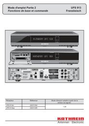
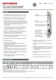
Low Noise Amplifier GPS<br />
860 10069<br />
– The low noise amplifier 860 10069 is designed <strong>for</strong> the use<br />
with train antennas with GPS.<br />
– It includes a preselection filter to prevent the interference in<br />
case of simultaneous operation at the frequency range<br />
380 – 2700 MHz <strong>and</strong> GPS.<br />
– The product fulfils the requirements according to EN 50155.<br />
Block Diagram<br />
Input<br />
TNC female<br />
b<strong>and</strong>pass<br />
filter GPS<br />
Additional features:<br />
amplifier<br />
b<strong>and</strong>pass<br />
amplifier<br />
filter GPS<br />
b<strong>and</strong>pass<br />
filter GPS<br />
Type No. 860 10069<br />
● The maximum input power at the input of the amplifier at<br />
the frequency range 380 – 960 MHz <strong>and</strong> 1710 – 2700 MHz<br />
is limited to +25 dBm.<br />
● The noise level at the GPS-frequency generated by the<br />
operation at the frequency range 380 – 960 MHz <strong>and</strong><br />
1710 – 2700 MHz should not exceed the thermal noise level<br />
at the input of the GPS-amplifier, otherwise the noise figure<br />
will be increased.<br />
Environmental conditions:<br />
● Temperature range: –25 °C … +45 °C (data as specified)<br />
–40 °C … +85 °C (extended range) * )<br />
● Protection class: IP 54 (DIN 40050 / IEC 144)<br />
(hanging installation position)<br />
bias-T<br />
Frequency 1575.42 MHz, L1-signal<br />
Gain 25 ±2 dB<br />
Noise figure < 2.0 dB<br />
VSWR (input, output) < 1.8<br />
Operation voltage 3.0 ... 5.5 V, ripple < 50 mV,<br />
supplied at inner conductor RF-output<br />
Operation current 3.0 – 3.5 V: < 25 mA<br />
3.6 – 5.5 V: < 40 mA<br />
Connector input TNC female<br />
Connector output N female<br />
Dimensions (w x h x l) 70 x 22 x 50 mm<br />
Mounting 4 holes, 4.5 mm diameter<br />
Output<br />
N female<br />
* ) Extended range of operation:<br />
Within an extended temperature range of –40 °C … +85 °C<br />
<strong>and</strong> an extended supplied voltage range of 3.2 V … 6.0 V<br />
operation is possible with the following restrictions:<br />
Noise figure: < 2.5 dB<br />
Gain: > 20 dB<br />
50<br />
4.4<br />
53<br />
70<br />
Input (Antenna)<br />
TNC<br />
N<br />
Output<br />
(DC +3.0 ... 5.5 V)<br />
7<br />
5<br />
30<br />
22<br />
93<br />
25
Installation Guidelines<br />
Abstract<br />
Quality is the key<br />
Train antennas made by <strong>Kathrein</strong> are well known<br />
as reliable <strong>and</strong> highly sophisticated products.<br />
Our antennas are distinguished by excellent voltage<br />
protection against accidentally high voltage contacts<br />
due to well developed grounding elements<br />
implemented in the overall design.<br />
Design<br />
Depending on frequency <strong>and</strong> design constrains<br />
<strong>Kathrein</strong> antennas are designed as λ/4 radiators or as<br />
λ/2 radiators. For proper functionality λ/4 radiators<br />
have to be mounted on a conductive surface creating<br />
a ground plane. Train antennas are usually vertical<br />
polarized. Impedance is 50 Ohm.<br />
<strong>Kathrein</strong> antennas are tested from an independent<br />
institute <strong>and</strong> type approved by the “Deutsche<br />
Bahn AG” (German Railway).<br />
26<br />
68 – 87,5 MHz 410 – 470 MHz<br />
Train antennas are faced to extreme environmental<br />
conditions <strong>and</strong> need to withst<strong>and</strong> tremendous<br />
operational conditions. The following documents<br />
should help to underst<strong>and</strong> functionality <strong>and</strong> learn<br />
more about proper installation procedures.<br />
Key features of <strong>Kathrein</strong> antennas to pass the<br />
“Deutsche Bahn AG” requirements is the ability to<br />
limit connector voltage to 60 V in case of contact<br />
with the high tension lines. Current flow of 40 kA<br />
over a time frame of 100 ms <strong>and</strong> high voltages of up<br />
to 42 kV could be applied under worst case<br />
conditions.<br />
Broadb<strong>and</strong> + GPS<br />
(incl. amplifier)
Installation Guidelines<br />
Installation<br />
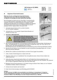
Ground Plane<br />
Fundamental RF basics require metallic surfaces <strong>for</strong><br />
certain antenna designs. Utilizing λ/4 technologies<br />
depends on a sufficient ground plane surface to<br />
finally distribute RF wave into the surroundings. Thus<br />
those particular antennas need to be mounted<br />
against a conductive surface to create the required<br />
ground plane.<br />
λ/4<br />
E - Field<br />
virtuell<br />
fieldlines<br />
electrical<br />
ground plane<br />
Figure 1: Electrical field <strong>and</strong> radiation pattern of a λ/4 antenna design<br />
3.1.1 Metallic Surfaces<br />
In most of the cases the roof of trains is made out of<br />
metallic materials. These materials have a reasonable<br />
conductivity to achieve best radiation results. For<br />
safety reasons these surfaces need to offer sufficient<br />
grounding to finally guide high voltages <strong>and</strong> currents<br />
to the ground.<br />
3.1.2 Non-Metallic Surfaces<br />
<strong>Trains</strong> designs appear more <strong>and</strong> more with nonmetallic<br />
surfaces mostly present at the front or the end<br />
of a train. Apparently those areas are preferred<br />
installation areas <strong>for</strong> antennas.<br />
As explained previously antennas require ground<br />
planes made out of conductive material. Several<br />
Each data sheet leaves detailed in<strong>for</strong>mation about<br />
surface size. We strongly recommend not to stay<br />
under the minimum mounting requirements. <strong>Antennas</strong><br />
easily will loose VSWR per<strong>for</strong>mance, <strong>and</strong> radiation<br />
pattern may change dramatically.<br />
10<br />
3 dB<br />
0<br />
Horizon<br />
designs may apply to create such a plane. Metallic<br />
foils might be placed underneath a non-metallic<br />
train body. Other metals might be laminated into<br />
Fiberglass constructions. The antenna flange needs<br />
to have good electrical contact to these additional<br />
ground planes<br />
The same m<strong>and</strong>atory rule applies as with metallic<br />
surfaces: A sufficient grounding of the antenna needs<br />
to be considered in the design. Any kind of grounding<br />
needs to h<strong>and</strong>le high currents <strong>and</strong> voltages, <strong>and</strong> finally<br />
lead it to the ground.<br />
27
Installation Guidelines<br />
Grounding<br />
In case of an accident or a failure of the high<br />
tension line (overhead contact line) high voltage<br />
<strong>and</strong> current might be applied to the antenna. To<br />
protect personal <strong>and</strong> equipment, connector voltage<br />
of the antenna is supposed not to exceed 60 V. To<br />
guarantee low connector voltages, antenna flanges<br />
need to be grounded thoroughly.<br />
• Unpainted areas near the four mounting holes of<br />
the antenna flange.<br />
To achieve best conductivity mounting surfaces at<br />
the antenna socket <strong>and</strong> the mating surface of the<br />
train should be clean. Any paint residues or other<br />
pollution needs to be removed prior to the mounting<br />
process.<br />
Mounting<br />
Most antennas are designed with a st<strong>and</strong>ardized foot<br />
print of the mounting socket. Dimensions are stated in<br />
the data sheets.<br />
Mounting Sockets<br />
Most antenna sockets offer four screw holes to tighten<br />
the flange against the mounting surface.<br />
We recommend the following:<br />
• Mounting against a separate flange with integrated<br />
mounting bolts. This flange is usually welded to the<br />
train.<br />
In general, mounting screws or nuts should not add<br />
more than 15 mm to the mounting surface, especially<br />
if cap nuts are used.<br />
In case of an antenna installation with screws<br />
through the antenna socket into the vehicle, particular<br />
attention should be paid to the sealing of the<br />
screws under consideration of the grounding<br />
instructions.<br />
28<br />
• In case of non-metallic roof surfaces with an additional<br />
ground plane of e. g. thin material, a separate<br />
grounding of the antenna mounting flange is<br />
required.<br />
Figure 2: Inside grounding<br />
grounding rod<br />
Mounting Position<br />
The antennas have to be mounted directly to the<br />
ground plane.<br />
Depending on the overall mounting situation (please<br />
refer to “Obstacles close to the antenna”) it’s tempted<br />
to elevate antennas against the trains roof with high<br />
flanges or other challenging constructions. To avoid<br />
mistuning <strong>and</strong> malfunctioning antennas it is m<strong>and</strong>atory<br />
not to follow these installation ideas. Resonance<br />
frequency, radiation pattern, <strong>and</strong> VSWR would change<br />
dramatically or could be lost completely.<br />
Figure 3: Low profile broad b<strong>and</strong> antenna with mounting screws
Installation Guidelines<br />
Sealing<br />
To avoid corrosion <strong>and</strong> leaky into the vehicle,<br />
antenna connectors need to be sealed against the<br />
mounting plate. Every <strong>Kathrein</strong> antenna is supplied<br />
with detailed mounting instructions. An O-ring is<br />
supplied with each antenna to seal the through hole<br />
into the vehicles body against the antennas<br />
connector. For certain types, this ring runs around the<br />
whole flange. To achieve advanced sealing mating<br />
Painting<br />
For optical reasons the color of train antennas sometimes<br />
has to match certain colors. <strong>Kathrein</strong> antennas<br />
are particularly suitable <strong>for</strong> subsequent, long-lasting<br />
painting since the visible parts (radomes) are<br />
generally made of fiberglass (polyester), to which<br />
paint adheres very well. A thin layer of paint eventually<br />
has only a negligible influence on the electrical<br />
characteristics.<br />
General remarks:<br />
• We recommend that painting is only per<strong>for</strong>med<br />
by qualified professional painting companies. If<br />
required painting on site may also be possible (<strong>and</strong><br />
permissible).<br />
Obstacles close to the antenna<br />
For proper wave propagation from the antenna into the<br />
surroundings a flat roof without any obstacles would be<br />
preferred.<br />
<strong>Trains</strong> sometimes have a number of structures <strong>for</strong><br />
multiple purposes on the trains top. Any obstacles<br />
Distances to other antennas<br />
The distance to other antennas depends on the<br />
required antenna isolation. This value has to be<br />
clarified with the suppliers of the installed mobile<br />
communication system.<br />
An isolation of 30 dB is a preferred value. As a<br />
rule over the thumb, a distance of approximately<br />
surfaces between the antenna socket <strong>and</strong> mounting<br />
flange/mounting surface are supposed of being<br />
flat.<br />
Sealing also needs to be per<strong>for</strong>med around mounting<br />
holes if no mounting flanges are used. Corrosion at<br />
mating surfaces between the antenna <strong>and</strong> the<br />
mounting plane is critical <strong>for</strong> proper function of the<br />
antenna.<br />
• We recommend that painting should only be applied<br />
to visible surfaces: e.g.<br />
– Fiberglass radome<br />
– Antenna socket, upper surface – please refer to<br />
instructions stated in our data sheets<br />
• The contact area on the lower part of the flange must<br />
be kept unpainted at all events.<br />
• Suitable commercial paints consist of one or two<br />
components. The manufacturer's instruction <strong>for</strong> use<br />
<strong>and</strong> processing must be observed. Paints with<br />
metallic effects or metallic components are not<br />
permissible.<br />
close to the antenna may impact radiation pattern <strong>and</strong><br />
radiated waves. It is difficult to leave general guidelines<br />
about minimum distances. As a rule over the thumb<br />
antennas should face no obstacles within a radius of<br />
approximately 1 m or more.<br />
5 –7 Lambda is required <strong>for</strong> antennas operating the<br />
same frequency b<strong>and</strong>.<br />
Due to the selectivity of different systems, antennas<br />
operating in different frequency b<strong>and</strong>s require<br />
distances that can be even smaller.<br />
29
Please contact <strong>for</strong>:<br />
Sales queries, orders, catalogues<br />
or CD-ROM:<br />
Fax: (++49)8031/184-820<br />
E-Mail: central.sales@kathrein.de<br />
Technical In<strong>for</strong>mation:<br />
Fax: (++49)8031/184-973<br />
E-Mail: antennas.mobilcom@kathrein.de<br />
Internet: www.kathrein.de<br />
KATHREIN-Werke KG . Telephone +49 8031 184-0 . Fax +49 8031 184-973<br />
Anton-<strong>Kathrein</strong>-Straße 1 – 3 . P.O. Box 10 04 44 . D-83004 Rosenheim . Germany<br />
9981.0496/1106/5/ZW/HA Subject to alteration.