9986252-DVB Satellite Receiver UFD 545 - Kathrein
9986252-DVB Satellite Receiver UFD 545 - Kathrein
9986252-DVB Satellite Receiver UFD 545 - Kathrein

Create successful ePaper yourself
Turn your PDF publications into a flip-book with our unique Google optimized e-Paper software.
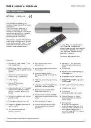
User's Guide<br />
<strong>DVB</strong> <strong>Satellite</strong> <strong>Receiver</strong><br />
for mobile applications <strong>UFD</strong> <strong>545</strong><br />
Order No. 260 497<br />
1
Foreword<br />
Vorwort<br />
Dear customer,<br />
This User's Guide is designed to help you to use the extensive functions of your<br />
new satellite receiver most effectively.<br />
We have made every effort to make the instructions as clear and understandable<br />
as possible and to keep them as short as necessary. We have added a small<br />
glossary of terms at the end of the User's Guide to facilitate understanding of<br />
certain technical expressions that do not lend themselves to translation. And to<br />
make sure you find what you are looking for, we have also included an index at the<br />
back.<br />
We wish you the very best reception and great pleasure with your new<br />
<strong>DVB</strong> satellite receiver.<br />
Your<br />
KATHREIN Team<br />
Should you, contrary to all expectations, experience problems with your receiver,<br />
please contact your dealer or our Hotline.<br />
Tel: #49 (0)8031/18 47 00<br />
Fax: #49 (0)8031/18 46 76<br />
Important information<br />
The channel allocations of the satellites and transponders are subject to frequent<br />
change. Consequently, in such cases, it may be necessary to readjust the channel<br />
settings even though the channels are preset at the factory corresponding to the<br />
latest channel allocations. You can obtain the information necessary for resetting<br />
the channels from SAT 1 video text, the Internet or corresponding TV and satellite<br />
magazines.<br />
3
Contents<br />
Inhalt<br />
Foreword................................................................................................................................................3<br />
Contents ................................................................................................................................................4<br />
Safety Information..................................................................................................................................7<br />
Important information on operation ......................................................................................7<br />
Longer periods of absence/thunderstorms ......................................................................................... 7<br />
Mains lead....................................................................................................................................... 7<br />
Cleaning.......................................................................................................................................... 7<br />
Playing children................................................................................................................................ 7<br />
Repair ............................................................................................................................................. 7<br />
Connections..................................................................................................................................... 7<br />
Setting-up location............................................................................................................................ 8<br />
Ventilation........................................................................................................................................ 8<br />
Moisture, sunlight, heat..................................................................................................................... 8<br />
Mains voltage................................................................................................................................... 8<br />
Earthing........................................................................................................................................... 8<br />
Controls, Indicators, Displays and Connections....................................................................................9<br />
Front view............................................................................................................................................9<br />
Rear view ............................................................................................................................................9<br />
Controls, indicators and displays on the front panel ................................................................................9<br />
Controls and connections at the rear .....................................................................................................9<br />
Remote control function buttons ..........................................................................................................10<br />
Switching over between Remote Control Command Sets....................................................................11<br />
Notes on Operation..............................................................................................................................12<br />
Menu concept ....................................................................................................................................12<br />
Button functions .................................................................................................................................12<br />
Alphanumeric entries..........................................................................................................................12<br />
Alphanumeric assignments of number buttons on the remote control.....................................................13<br />
Language selection - OSD..................................................................................................................13<br />
Connection and Startup .......................................................................................................................14<br />
To connect the receiver ......................................................................................................................14<br />
Sat-IF connection............................................................................................................................14<br />
Analogue and digital TV...................................................................................................................14<br />
Presetting of the receiving system....................................................................................................14<br />
LNB supply voltage .........................................................................................................................15<br />
Modulator connection......................................................................................................................15<br />
TV and video recorder connection ....................................................................................................15<br />
Audio connection.............................................................................................................................15<br />
Inserting batteries in the remote control ............................................................................................15<br />
Switching on for the First Time............................................................................................................16<br />
The first steps ....................................................................................................................................16<br />
Factory setting of the receiver.............................................................................................................16<br />
OSD On Screen Display .......................................................................................................................17<br />
Important on-screen displays ..............................................................................................................17<br />
TV channel identifier........................................................................................................................17<br />
Radio channel identifier ...................................................................................................................17<br />
Error message ................................................................................................................................17<br />
TV channel list................................................................................................................................17<br />
Radio channel list............................................................................................................................17<br />
Channel selection ................................................................................................................................18<br />
Selecting a TV channel.......................................................................................................................18<br />
Reception status – digital.................................................................................................................18<br />
Reception status - analogue.............................................................................................................19<br />
Selecting a TV channel by number entry .......................................................................................19<br />
4
Contents<br />
Switching over to radio channel...........................................................................................................19<br />
Selecting a radio channel by number entry ....................................................................................20<br />
Timer Settings......................................................................................................................................21<br />
Sound Settings ....................................................................................................................................22<br />
Setting the volume..............................................................................................................................22<br />
Stereo and two-channel sound reproduction ........................................................................................22<br />
Mute...............................................................................................................................................22<br />
Channel lists - TV/Radio.......................................................................................................................23<br />
Selecting TV and radio channels last received .....................................................................................23<br />
Favourite channels.............................................................................................................................23<br />
To sort the channels...........................................................................................................................24<br />
To delete a channel............................................................................................................................24<br />
To add a channel ...............................................................................................................................25<br />
To add an analogue channel...............................................................................................................26<br />
Analogue channel lists .......................................................................................................................26<br />
Adding/Removing <strong>Satellite</strong>s.................................................................................................................27<br />
To set up satellites .............................................................................................................................27<br />
To enter a satellite name ....................................................................................................................28<br />
To remove satellites ...........................................................................................................................28<br />
Current Channel Overview ..................................................................................................................29<br />
Password .............................................................................................................................................30<br />
Factory setting ................................................................................................................................30<br />
Entering a password........................................................................................................................30<br />
Parental control..................................................................................................................................31<br />
Operation from the Front Panel............................................................................................................32<br />
Operation in exceptional cases ...........................................................................................................32<br />
Setting System Parameters..................................................................................................................33<br />
System parameters ............................................................................................................................33<br />
Parental control...............................................................................................................................33<br />
System information..........................................................................................................................33<br />
Local time/timer...............................................................................................................................33<br />
Timer menu ....................................................................................................................................34<br />
Summer time ..................................................................................................................................34<br />
TV type...........................................................................................................................................34<br />
Picture format .................................................................................................................................34<br />
Screen............................................................................................................................................34<br />
A/V mode .......................................................................................................................................34<br />
Mod.typ..........................................................................................................................................35<br />
Mod.Ch ..........................................................................................................................................35<br />
OSD colour.....................................................................................................................................35<br />
OSD-Trans .....................................................................................................................................35<br />
Installation Menu..................................................................................................................................36<br />
LNB configuration............................................................................................................................36<br />
Oscillator frequency L.O. ..............................................................................................................36<br />
Changing the oscillator frequency .................................................................................................37<br />
Operation....................................................................................................................................37<br />
Standby.......................................................................................................................................37<br />
Receiving two satellites ................................................................................................................37<br />
DiSEqC-setting ............................................................................................................................38<br />
Antenna settings .............................................................................................................................38<br />
<strong>Satellite</strong> scan ..................................................................................................................................38<br />
TP setup/scan.................................................................................................................................39<br />
Digital transponder.......................................................................................................................39<br />
Analogue transponder ..................................................................................................................40<br />
DiSEqC (UFO) setup.......................................................................................................................41<br />
5
Contents<br />
6<br />
22 kHz signal...............................................................................................................................41<br />
Tone-burst and DiSEqC-signal......................................................................................................41<br />
Tone burst...................................................................................................................................42<br />
DiSEqC .......................................................................................................................................42<br />
DiSEqC repeat.............................................................................................................................42<br />
UFO mini.....................................................................................................................................42<br />
Remote frequency .......................................................................................................................42<br />
UFO micro...................................................................................................................................42<br />
Factory setting ................................................................................................................................43<br />
Analogue Settings................................................................................................................................44<br />
Video menu .......................................................................................................................................44<br />
Name.............................................................................................................................................44<br />
Frequency ......................................................................................................................................44<br />
Polarity...........................................................................................................................................44<br />
Band ..............................................................................................................................................44<br />
Low threshold .................................................................................................................................44<br />
Contrast .........................................................................................................................................44<br />
Decoder..........................................................................................................................................45<br />
HDP mode......................................................................................................................................45<br />
Startprog ........................................................................................................................................45<br />
Audio menu .......................................................................................................................................45<br />
Audio mode ....................................................................................................................................45<br />
Frequency left/right..........................................................................................................................46<br />
Bandwidth.......................................................................................................................................46<br />
DNR...............................................................................................................................................46<br />
De-emphasis ..................................................................................................................................46<br />
Video Recorder Connection.................................................................................................................47<br />
Recording..........................................................................................................................................47<br />
Playback ...........................................................................................................................................47<br />
Analogue Decoder Connection ............................................................................................................48<br />
Data Transfer from <strong>Receiver</strong> to <strong>Receiver</strong> .............................................................................................49<br />
Preparation........................................................................................................................................49<br />
Transferring channel list ..................................................................................................................49<br />
Transferring operating software........................................................................................................49<br />
Technical Reference ............................................................................................................................50<br />
Technical features ..............................................................................................................................50<br />
Technical data ...................................................................................................................................51<br />
Accessories .......................................................................................................................................52<br />
SCART socket assignments ...............................................................................................................52<br />
Connection examples .........................................................................................................................53<br />
Connection arrangement 1:..............................................................................................................53<br />
Connection arrangement 2:..............................................................................................................54<br />
Glossary, Abbreviations....................................................................................................................... 55<br />
Glossary of Technical Terms ...............................................................................................................56<br />
Service .................................................................................................................................................58<br />
Index ....................................................................................................................................................59
Safety Information<br />
Sicherheitshinweise<br />
Important information on operation<br />
In the following section you will find important information on operation, the place of<br />
installation and connection of the receiver.<br />
Please read this information carefully before you start up your receiver.<br />
Longer periods of absence/thunderstorms<br />
Always switch off the receiver with the power switch at the front left in the event of<br />
longer periods of absence and during a thunderstorm. This also applies to any<br />
other devices that may be connected to the receiver.<br />
Mains lead<br />
Cleaning<br />
Playing children<br />
Repair<br />
Connections<br />
If timer programming is set make sure the receiver is switched on in good time<br />
before the set recording time.<br />
Take particular care to ensure that the power supply cable is not damaged. Never<br />
operate the device with a defective mains lead.<br />
Disconnect the receiver from the power supply before you clean it. Use a soft dry<br />
cloth for this purpose. Only clean the surface of the casing.<br />
Never open the casing. Contact with parts on the inside of the receiver poses a risk<br />
of electric shock.<br />
Make sure that children do not insert objects into the ventilation slots. This is a<br />
source of danger and fatal injury by electric shock, and may cause a short-circuit.<br />
Only have qualified service personnel carry out repairs or adjustments to your<br />
receiver. Unauthorized opening up of the receiver and attempts at repair will<br />
invalidate the guarantee.<br />
Unauthorized tampering with the device can jeopardize the electrical safety of the<br />
receiver.<br />
The manufacturer shall not be liable for accidents to the user as the result of the<br />
receiver being opened up.<br />
Incorrect connection can lead to problems in operation or cause defects in the<br />
device.<br />
7
Safety Information<br />
Setting-up location<br />
Ventilation<br />
8<br />
Important information on setting-up location and assembly<br />
All electronic devices generate heat. The rise in temperature, however, is within a<br />
safe range. Sensitive surfaces of furniture and veneers can over time discolour<br />
slightly due to the constant effects of heat. The feet of the receiver may also<br />
discolour when in contact with treated surfaces. If necessary, place the receiver on<br />
a suitable base.<br />
The heat generated in this receiver is adequately dissipated. Nevertheless, never<br />
install the receiver in a cabinet or on a shelf with insufficient ventilation. Never<br />
cover or close off the cooling slots on the device.<br />
Never place objects on the receiver and maintain a minimum clearance of 10 cm<br />
above the device to ensure the heat is carried off effectively.<br />
Moisture, sunlight, heat<br />
Protect the receiver from moisture, dripping and splash water.<br />
Mains voltage<br />
Earthing<br />
Do not place the receiver near a source of heating and never expose it to direct<br />
sunlight<br />
Operate the receiver only with a mains voltage of 230 V/50 Hz or connected to a<br />
battery 12 V/24 V DC vehicle electrical system.<br />
First connect the antenna and the television set before connecting the receiver to<br />
the mains power supply and switching on.<br />
The parabolic antenna must be earthed according to instructions. Corresponding<br />
local and/or VDE regulations must be observed.
Controls, Indicators, Displays and Connections<br />
Bedienelemente, Anzeigen und Anschlüsse<br />
In this section you will find a short description of all controls, indicators, displays<br />
and connections. The button symbols used here are also used in the description of<br />
the operating steps.<br />
Front view<br />
(panel folded down)<br />
CARAVAN DIGITAL ANALOG RECEIVER<br />
Rear view<br />
Controls, indicators and displays on the<br />
front panel<br />
1 ON/OFF switch (with mains disconnection)<br />
2 Menu button to display and exit the menus<br />
or submenus<br />
3 Acknowledgement for remote control signal<br />
4 Select button<br />
to confirm a selection<br />
5 Operation indicator<br />
6 Standby indicator<br />
REMOTE TV/SAT STAND BY<br />
7 Cursor buttons to move through menu and<br />
channel lists as well as to set the volume<br />
(corresponds to remote control)<br />
8 LED display (four-digit, 7-segment display)<br />
to show channel number and time.<br />
9 Press catch for front panel<br />
To open press lightly on upper right side<br />
MENU<br />
SELECT<br />
1 2 3 4 5 6 7 8 9<br />
Controls and connections at the rear<br />
1 Antenna input (terrestrial)<br />
2 Modulator output<br />
3 Audio output<br />
2 Cinch socket outputs, left and right<br />
channel<br />
4 Digital sound output (AC3) – Cinch socket<br />
output<br />
5 Video output (FBAS)<br />
6 SCART socket TV connection<br />
7 SCART socket VCR/AUX connection<br />
8 DATA input/output socket<br />
Interface for serial data transmission<br />
(service)<br />
9 <strong>Satellite</strong> IF signal input<br />
Output of LNB supply voltage and control<br />
signals (22 kHz and DiSEqC 1.1)<br />
10 <strong>Satellite</strong> IF signal output<br />
Bridged Sat-IF signal<br />
11 <strong>Satellite</strong> IF input for analogue reception<br />
12 Mains power input 230 V AC<br />
13 DC voltage input 12…24 V<br />
Digital Video Broadcasting<br />
1 2 3 4 5 6 7 8 9 10 11 12 13<br />
9
Controls, Indicators, Displays and Connections<br />
Remote control function buttons<br />
10<br />
A<br />
To switch between<br />
remote control<br />
settings<br />
F<br />
To select favorites<br />
z<br />
Channel<br />
information<br />
i<br />
To select<br />
channel list<br />
o<br />
u<br />
To select channel/<br />
submenus and menu<br />
points<br />
l<br />
To switch mute<br />
ON/OFF<br />
1...0<br />
To select<br />
channels, parental<br />
control,<br />
LO frequency, etc.<br />
A/B M<br />
F L<br />
OK<br />
TV<br />
e<br />
To turn satellite<br />
receiver ON - standby<br />
M<br />
To select<br />
main menu<br />
L<br />
Last channel<br />
and exit<br />
T<br />
To set SCART<br />
connection<br />
radio OFF<br />
- +<br />
To set volume/<br />
menu points<br />
O<br />
To confirm<br />
submenus and menu<br />
points<br />
R<br />
To turn radio ON/OFF<br />
s<br />
Sound selection<br />
menu<br />
stereo/mono<br />
language selection
Switching over between Remote Control Command Sets<br />
g umschalten<br />
The remote control features 2 command sets, making it possible to operate<br />
2 receivers independently of each other in one room (not together with a twin<br />
receiver).<br />
Note For this purpose, program one receiver on the command set 1 and the second<br />
receiver on the command set 2.<br />
• Switch on receiver 1 and receiver 2 off with the power switch.<br />
⇒ Press and hold the A button.<br />
⇒ Enter "901" with the number buttons.<br />
• To adopt the code, press the e button to switch receiver 1 to standby and<br />
then switch off the device at the power switch.<br />
• Switch on receiver 2.<br />
⇒ Press and hold the A button.<br />
⇒ Enter "902" with the number buttons.<br />
• To adopt the code, press the e button to switch receiver 2 to standby and<br />
then back into operation. Now switch on receiver 1 again.<br />
⇒ Press and hold the A button.<br />
⇒ Enter "903" with the number buttons.<br />
Note When carrying out the first two settings, the remote control must be directed at the<br />
respective receiver (when switched on).<br />
By pressing the A button, you can now switch between the two command sets A<br />
and B (toggle function) and alternately operate both receivers.<br />
Command set 1 is always active as the on-delivery setting.<br />
Note If you are operating only one receiver and the active command set is switched over<br />
by mistake so that this receiver can no longer be operated, the remote control can<br />
be easily switched back to command set 1 by following the procedure described<br />
above.<br />
11
Notes on Operation<br />
Bedienungshinweise<br />
Menu concept<br />
12<br />
The menu concept is based on logical operating sequences.<br />
Note: Coloured backgrounds are used to emphasize the selected menus, submenus and<br />
menu items as well as the parameters to be set. The menus are to a large extent<br />
self-explanatory. You will find information relating to the selected menu point in the<br />
information box displayed under the menu.<br />
Button functions<br />
Press the M button to select the main<br />
menu and press the ou buttons to<br />
select the submenus.<br />
Press O to access the submenus.<br />
The items in the submenus are selected<br />
by pressing the ou buttons.<br />
The settings allocated to specific menu items are executed either by pressing the<br />
-+ buttons or the number buttons.<br />
Press L or M to exit the main menu, submenus and menu items.<br />
i is a changeover button (main channel list or favourite list) with menu function.<br />
Press L to exit the setting.<br />
T is a changeover button. Identifier self-deleting.<br />
s is a switch-on button with menu functions. Press the button again to exit.<br />
z is a switch-on button with menu functions. Press the button again to exit.<br />
F is a switch-on button with menu functions. Press the button again to exit.<br />
R is a function selection button. Press once again to change function.<br />
l is a function selection button. Press once again to change function.<br />
Alphanumeric entries<br />
Use the number buttons to enter the channel and satellite names. They produce<br />
numbers and letters in the name fields of the corresponding menus. Position the<br />
bar cursor on the name field. The first position automatically assumes a dark<br />
background. You can now also enter letters with the number buttons by pressing<br />
the corresponding button several times. For example, Q, Z and — are additionally<br />
allocated to the "1" button (see table on next page).
Notes on Operation<br />
Alphanumeric assignments of number buttons on the remote control<br />
Button 1 X 2 X 3 X 4 X<br />
1<br />
2<br />
3<br />
4<br />
5<br />
6<br />
7<br />
8<br />
9<br />
0<br />
1 Q Z -<br />
2 A B C<br />
3 D E F<br />
4 G H I<br />
5 J K L<br />
6 M N O<br />
7 P R S<br />
8 T U V<br />
9 W X Y<br />
0 SPACE<br />
Language selection - OSD<br />
To select the language for the on-screen menus press:<br />
M C ou C menu language C -+ C English C M<br />
The available languages are German, French, Italian, Spanish, Portuguese, Dutch,<br />
Greek and Turkish.<br />
13
Connection and Startup<br />
Anschluss und Inbetriebnahme<br />
The following section is specifically intended for the specialist dealer. You only<br />
need to read this section if you are carrying out the installation yourself.<br />
To connect the receiver<br />
Sat-IF connection<br />
14<br />
You will find sample configurations in the section "Connection examples".<br />
First carry out all installation work before connecting the receiver to the mains<br />
power supply.<br />
Refer to the information provided in the section on "Safety".<br />
Connect the Sat-IF input of the receiver to the satellite receiving system (satellite<br />
dish).<br />
Use a coaxial cable with a standard F connector for this purpose.<br />
If you need to fit the F-connector onto the cable,<br />
• strip the cable insulation as shown in the diagram (you will need to fold back<br />
the braid) and<br />
• slide the F-connector onto the cable, then turn it clockwise until it locks.<br />
When fitting the connector make sure that no wires of the shield braid make<br />
contact with the inner conductor. This could otherwise cause a short-circuit.<br />
The quality of the reception signal depends on a good connection!<br />
Analogue and digital TV<br />
To ensure you can receive digital and analogue channels, connect the IF OUTPUT<br />
socket with the IF INPUT ANALOG socket at the rear of the receiver. Use the coax<br />
jumper provided as an accessory for this purpose.<br />
Presetting of the receiving system<br />
Make sure that your satellite antenna system transmits both the low band as well<br />
as the high band for analogue and digital reception. For digital reception, your<br />
single satellite antenna (dish) must be equipped with at least one universal LNB.<br />
The control signals for conventional receiving systems (satellite dishes) are preset,<br />
i.e. 14/18 V for polarization changeover and 22 kHz switching signal for LOW/HIGH<br />
band changeover on multifeed reception systems.<br />
The presetting will need to be changed in the installation menu, menu point<br />
"DiSEqC" if UFO or tone burst switching matrices are used in the receiving system.<br />
Refer to the section "Installation menu, DiSEqC menu“ for this purpose.<br />
It is important that you observe the application information provided for the matrix<br />
used.
Connection and Startup<br />
LNB supply voltage<br />
If the feed system (LNB) is powered by an external supply voltage and the LNB<br />
supply voltage is not used for switching over polarity (e.g. <strong>Kathrein</strong> feed system<br />
UAS 330), the LNB supply of the receiver must be set to "OFF" (see section<br />
"Installation menu, LNB configuration").<br />
Modulator connection<br />
If your TV set is not equipped with a SCART socket, you can connect the receiver<br />
by means of a coaxial cable. (See "Technical reference" at the end of this User's<br />
Guide.)<br />
For this purpose, connect the modulator output of the receiver to the antenna input<br />
of the TV set.<br />
The TV set must be preset to UHF channel 38. The modulator of your receiver<br />
"transmits" on this channel (factory setting).<br />
Note Stereo reproduction is not possible in this configuration! And a decoder for pay-TV<br />
cannot be connected!<br />
TV and video recorder connection<br />
Audio connection<br />
Inserting batteries in the remote control<br />
To use the receiver together with a video recorder, loop through the receiver signal<br />
via the video recorder (antenna input and output). The output channel of the video<br />
recorder must be selected such that the receiver signal is not adversely affected<br />
and vice versa. Refer to the corresponding information provided in the User's<br />
Guide of your video recorder. Also refer to the connection examples at the end of<br />
this User's Guide!<br />
• Use a SCART cable to connect the satellite receiver (TV SCART) and TV set.<br />
If your TV set is equipped for stereo output, you can receive the sound in stereo via<br />
the SCART connection.<br />
• Also use a SCART cable to connect the satellite receiver (VCR/AUX SCART)<br />
and the video recorder.<br />
If you wish to reproduce the sound via a HiFi system, connect a corresponding<br />
Cinch cable from the audio Cinch sockets on the receiver to the input sockets on<br />
your HiFi system.<br />
If your HiFi system features a digital input or you have a digital Dolby system, you<br />
can connect it to the digital output.<br />
Remove the cover on the battery compartment on the underside of the remote<br />
control.<br />
• Insert the two supplied batteries in the remote control. Ensure correct polarity<br />
of the batteries, the + and – markings are indicated inside the battery<br />
compartment.<br />
• Slide the cover back into the casing and lock in position.<br />
Used batteries are special waste! Therefore do not throw batteries into the<br />
household waste but rather deposit them at a collection depot for old batteries!<br />
15
Switching on for the First Time<br />
Erste Inbetriebnahme<br />
The first steps<br />
16<br />
Connect the receiver to the mains power supply or vehicle electrical system. Use<br />
the supplied connection cable for this purpose. Never connect both cables at the<br />
same time!<br />
Switch on the receiver by pressing the power button at the front of the unit.<br />
You will see "- - - -“ in the LED display.<br />
The operation indicator LED lights red, the receiver is now in standby mode.<br />
Switch on your TV set.<br />
Select an AV channel number on the TV set or select channel 38 if the modulator<br />
output is connected.<br />
Switch on the receiver by pressing the e button on the remote control.<br />
The orange LED at the front end of the receiver flashes every time a button on the<br />
remote control is pressed.<br />
You will see the first factory preset channel on your TV screen. An information bar<br />
indicating the channel provider, the time, the timer settings, the channel status and<br />
the channel title will be displayed in the bottom section of the screen provided the<br />
corresponding data are transmitted. The number of the channel memory appears in<br />
the LED display.<br />
The red standby indicator goes out.<br />
Factory setting of the receiver<br />
You can now receive the TV and radio channels preset at the factory and select<br />
them by pressing the ou buttons. Press the R and ou buttons to<br />
select radio channels. Press the R or T button to return to TV channels.<br />
Refer to the section "Channel lists – TV/radio" for information on how to set up and<br />
save other TV and radio channels.<br />
The reception status last set always reappears when the receiver is switched on.<br />
If the message "bad or no signal" appears on the screen in addition to an onscreen<br />
display indicating the channel last received, you will need to check the<br />
system installation and/or the receiver settings. If this problem only applies to<br />
individual channel slots, the problem may be due to an interruption in the<br />
transmission signal or a fault in the receiving system (cable or satellite system).<br />
In this case, first check the connection configuration and then check whether the<br />
basic settings of your receiver are correct for your system. In the case of doubt,<br />
have a specialist do this for you.<br />
Your receiver is preprogrammed to receive the ASTRA and HotBird satellites. You<br />
will normally need to make no further settings. To receive both satellite systems or<br />
other satellites you will require a multifeed arrangement with at least two LNBs in<br />
front of the satellite dish if you are not connected to a communal or party system.<br />
Please ask your dealer.<br />
Before you change the basic settings of your receiver, note down the settings in<br />
the form provided at the end of this User's Guide. In this way, you will be able to<br />
restore the original settings at any time.
OSD On-Screen Displays<br />
Bildschirmeinblendungen / OSD On Screen Display<br />
Important on-screen displays<br />
The receiver functions are controlled by a microprocessor and extensive software.<br />
The following explanations are intended to improve understanding of all<br />
procedures and to minimise the risk of mistakes.<br />
TV channel identifier<br />
Radio channel identifier<br />
Error message<br />
TV channel list<br />
Radio channel list<br />
The channel identifier is displayed for<br />
several seconds every time the channel is<br />
changed or by pressing the O button.<br />
The I indicates that a channel is received even if no picture can be seen (e.g.<br />
radio). The film symbol indicates a TV channel with the selected channel shown<br />
next to it and whether video text is received. The current time, start time and end<br />
time of the current programme are shown on the next line provided these data are<br />
transmitted. The + in the third line stands for the channel selection from the main<br />
channel list. If the favourite list is selected, you will see the "apple" symbol at this<br />
point. This is followed by the set sound reproduction mode (depending on the<br />
direction of the symbolized sound waves, mono left, mono right or stereo can be<br />
set, the digit indicates the number of sound channels). The channel title is shown in<br />
the box on the right.<br />
The identifier for the set radio channel has<br />
the same configuration. A music note at<br />
the top left indicates that this is a radio<br />
channel. Programme times and text are displayed only if the corresponding data<br />
are transmitted with the signal.<br />
"Bad or no signal" indicates that there is a<br />
fault in the reception system or in the<br />
receiver settings or the transponder is not<br />
transmitting. Instead of the I, the channel<br />
identifier shows a satellite antenna together with the message "bad or no signal".<br />
Check the SAT-IF connection and the LNB configuration. As an aid, refer to the list<br />
of service settings provided at the end of this User's Guide.<br />
Press the i button to show the channel<br />
list. A + for the main channel list or the<br />
"apple" symbol is indicated at the top left.<br />
The list can be changed by pressing the<br />
button again. Information relating to the<br />
received satellites, the polarization, the<br />
symbol rate, scrambling, favorite or<br />
standard channel and the parental control<br />
is provided in the column below the<br />
symbol. The column on the left contains<br />
information relating to the channel, the<br />
channel provider and whether the channel is normally scrambled. The required<br />
channel can be selected with the bar cursor and confirmed by pressing the<br />
O button.<br />
See above. The same applies to the radio channel list.<br />
17
Channel selection<br />
Programmemwahl<br />
Selecting a TV channel<br />
18<br />
This section describes how you select analogue and digital TV channels with your<br />
receiver and how you can set the required volume.<br />
This description of the functions assumes that the receiver has been connected<br />
correctly.<br />
If you wish to connect the receiver yourself, please read the section "Connection<br />
and start-up" beforehand.<br />
Reception status – digital<br />
The following information describes how to select digital reception of other<br />
channels and shows what the on-screen displays look like.<br />
After switching on the receiver, simply press the ou buttons in order to<br />
select other TV channels in their ascending or descending order in the channel<br />
memory.<br />
Every time you press the button, an on-screen display shows you the selected<br />
channel together with the time, the programme start and end times as well as the<br />
channel title in the information box provided these data are transmitted together<br />
with the signal.<br />
By pressing the O button, you can leave<br />
this information box permanently<br />
displayed or switch it off by pressing<br />
the<br />
button once again.<br />
You will receive the "channel scrambled"<br />
message for scrambled channels.<br />
A further option of selecting a different channel is to press the i button. The TV<br />
channel list is now displayed. In the left column it will provide information relating to<br />
the received satellites, the transponder and its transmission frequency, the<br />
polarization, the symbol rate and the scrambling of digital channels. The right side<br />
shows the channel number, the channel broadcaster and the type of reception<br />
signal (analogue/digital).<br />
By pressing the ou buttons you jump to the next channel and by pressing<br />
the -+ buttons you jump to the neighbouring page.<br />
Confirm your selection by pressing the<br />
O button.<br />
Press the L button to exit the channel<br />
list and remain in the channel already set.<br />
If you have now selected an analogue<br />
channel, as confirmation, the plain white<br />
display for this type of transmission will<br />
appear (see below).
Channel selection<br />
Reception status - analogue<br />
You can, of course, select other channels by pressing the ou buttons while<br />
receiving an analogue channel. The selection of analogue channels is indicated by<br />
the information bar being displayed briefly in white, e.g.:<br />
way as with the digital channels.<br />
TV 59 DER KINDERKA STEREO<br />
By pressing the O button, you can see<br />
the selected channel in the same form.<br />
Press the i button to see the channel<br />
list indicated in white in the display. It<br />
shows the memory location, the channel<br />
name and the reception type "A" or "D"<br />
(analogue or digital). By pressing the<br />
ou buttons and the -+ buttons<br />
you can jump to the next page in the same<br />
Press the O button to select the required channel and press the L button to<br />
exit the channel list and remain in the channel already selected.<br />
If you have now selected a digital channel, as a confirmation, the coloured display<br />
for this type of transmission will appear.<br />
Selecting a TV channel by number entry<br />
You can select a different TV channel during a current TV channel by entering the<br />
channel location number. Use the number buttons 1 to 0 for the purpose of<br />
entering the channel location number.<br />
Example You wish to select the TV channel "DSF". This channel is stored under the channel<br />
location number 015. (The order of TV channels is defined in the channel memory<br />
and therefore only serves as an example here.)<br />
To select this channel, press the numbers 1 and 5 one after the other. The<br />
receiver waits for about 3 seconds for entry of the next number.<br />
Follow the same procedure for all other channels – i.e. also channels with threedigit<br />
channel location numbers. You do not have to enter leading zeros.<br />
Switching over to radio channel<br />
You can switch over from a TV channel to a radio channel.<br />
Press the R button on the remote control for this purpose.<br />
The receiver switches over to the channel location of the radio channels last set.<br />
You can return to the TV channel by pressing the same button or T. The<br />
corresponding display relating to the received channel, i.e. as when selecting the<br />
TV channels, appears on the screen. The LCD display shows a small "r" together<br />
with the channel location number.<br />
The screen will be blanked out after several seconds.<br />
19
Channel selection<br />
Reception status - radio<br />
20<br />
After switching over the receiver, simply press the ou buttons to select<br />
other radio channels in their ascending or descending order in the channel<br />
memory.<br />
Every time you press the button, an on-screen display shows you the selected<br />
channel together with the time, the programme start and end times as well as the<br />
channel title in the information box provided these data are transmitted together<br />
with the signal.<br />
By pressing the O button, you can leave<br />
this information box permanently<br />
displayed or switch it off by pressing the<br />
button once again.<br />
A further option of selecting a different channel is to press the i button. The<br />
radio channel list is now displayed. In the left column it will provide information<br />
relating to the received satellites, the transponder and its transmission frequency,<br />
the polarization, the symbol rate and the scrambling of digital channels. The right<br />
side shows the channel number, the channel broadcaster and the type of reception<br />
signal (analogue/digital). By pressing the ou buttons you jump to the next<br />
channel and by pressing the -+ buttons you jump to the neighbouring page.<br />
Confirm your channel selection by pressing the O button, press the L button to<br />
exit the channel list and remain in the channel already set.<br />
Selecting a radio channel by number entry<br />
You can select a different radio channel during a current radio channel by entering<br />
the channel location number. Use the number buttons 1 to 0 for the purpose<br />
of entering the channel location number.<br />
Example You wish to select the radio channel "DLR-Berlin". This channel is stored under the<br />
channel location number 015. (The order of radio channels is defined in the<br />
channel memory and therefore only serves as an example here.)<br />
To select this channel, press the numbers 1 and 5 one after the other. The<br />
receiver waits for about 3 seconds for entry of the next number.<br />
Follow the same procedure for all other channels – i.e. also channels with threedigit<br />
channel location numbers. You do not have to enter leading zeros.
Timer Settings<br />
You can use the timer for recording a programme with a video recorder on time.<br />
Seven timers are available which you can set to different channels as well as start<br />
and end times.<br />
To access the timer setting, press M to enter the main channel menu, uo<br />
to go to system parameters, followed by O and uo to local time / timer<br />
and O. You now see the display shown below.<br />
You can select and set<br />
• the channel type, TV or radio,<br />
• the channel location number with channel name,<br />
• the start time (date, month, year, hour, minute)<br />
• the stop time and<br />
• the timer status (inactive/once/daily/weekly)<br />
Press the ou buttons to move the<br />
cursor to the timer you require and confirm<br />
it by pressing O. Press L to exit the<br />
timer again.<br />
Incorrect time settings will be rejected.<br />
for seven timers. You must enter leading zeros for the time settings.<br />
Use the -+ and the number buttons to make the required setting.<br />
The current time that you must re-enter appears under the start time. If no other<br />
setting is entered, the end time will be set automatically to the same date and one<br />
hour after the start time.<br />
Finally confirm the settings by pressing M or L three times.<br />
21
Sound Settings<br />
Toneinstellungen<br />
22<br />
All setting options apply to analogue and digital TV modes as well as radio mode.<br />
Setting the volume<br />
Make sure that the volume of the TV set is set to the room volume.<br />
Set the required volume level by pressing<br />
the -+ buttons on the remote control of<br />
the receiver. A bar indicator with 31 segments is displayed on the screen to show<br />
the set volume. The same procedure also applies to analogue reception.<br />
Stereo and two-channel sound reproduction<br />
Modulator connection<br />
Mute<br />
(for radio and digital TV reception only)<br />
Stereo sound is not possible if the receiver signal is reproduced via the modulator.<br />
The channel identifier that you can display by pressing the O button shows the<br />
set sound reproduction. (Depending on the direction of the symbolized sound<br />
waves – under the displayed time – mono left, mono right or stereo can be set. The<br />
digit indicates the number of transmitted sound channels). The channel title is<br />
shown in the box on the right.<br />
Press the s button to call up the menu<br />
for sound and language selection. You<br />
can now make the required settings, e.g.<br />
language selection, provided the<br />
corresponding data are contained in the<br />
reception signal. Press the button once again to exit the menu.<br />
Press the l button on the remote control to mute the sound. This symbol l<br />
appears on the screen.<br />
Press the l button again to restore the sound. The standard volume display bar<br />
is then shown for several seconds.<br />
Although you can change the channel while in mute mode, it will remain muted until<br />
this mode is cancelled or you correct the volume.
Channel Lists – TV/radio<br />
The channels/channels set at the factory can be changed in the channel set-up<br />
menu. Select the menu by pressing the M button, the ou buttons as well<br />
as -+ for TV or radio and O. If stored, a password must be additionally<br />
entered.<br />
Due to the associated on-screen displays, all settings and editing must be made<br />
from a digital channel slot.<br />
Selecting TV and radio channels last received<br />
Favourite channels<br />
Press the F button to show on the screen the four channels you last received.<br />
The arrows correspond to the cursor buttons ou-+. The allocated channel<br />
can then be selected by pressing these buttons.<br />
If you call up this function from an<br />
analogue channel, the display will appear<br />
on a white screen background. The<br />
background will be blue when this function<br />
is selected from a digital channel.<br />
You can arrange and sort your favourite digital TV and radio channels, e.g. all<br />
German-language channels or channels that have no commercial breaks. These<br />
channels are identified by the "apple" symbol in the TV or radio channel lists.<br />
Select the "apple" symbol by pressing the<br />
-+ buttons, confirm your selection with<br />
O and the line with the current channel<br />
will be highlighted by a coloured bar in the<br />
list.<br />
The bar can be shifted page-by-page or<br />
line-by-line by pressing the -+ and<br />
ou buttons.<br />
You can now mark the highlighted line with the "apple" symbol by pressing the<br />
O button.<br />
The symbol can be cancelled by pressing the O button once again.<br />
Press the M button 3 times to return to the TV screen. Confirmation is given that<br />
your changes have been saved and the information display of the channel currently<br />
received appears for several seconds on the screen.<br />
Press the i button twice to call up the favourites list. You can now select your<br />
preset favourite channels by pressing the -+ or ou buttons and O.<br />
23
Channel Lists – TV/radio<br />
To sort the channels<br />
To delete a channel<br />
24<br />
You can sort TV and radio channels as<br />
required. The channels are sorted by<br />
shifting the entries in the "TV" or "radio"<br />
channel lists.<br />
Press the main menu button M to<br />
access the main menu:<br />
Select "channel list" by pressing the<br />
ou buttons.<br />
With the -+ buttons you can now choose whether you wish to edit the TV or radio<br />
list and confirm your selection with O.<br />
You now see the required channel list on the screen.<br />
Press the -+ buttons to select the item "✥", confirm your selection with O and<br />
the line with the current channel will be highlighted by a coloured bar in the list.<br />
The bar can be moved page-by-page or line-by-line with the -+ and ou<br />
buttons.<br />
The highlighted line can now be defined by pressing the O button and shifted to<br />
the required position with the -+ and ou buttons and saved in the<br />
corresponding channel slot by pressing O.<br />
Press the M button 3 times to return to the TV screen. Confirmation is given that<br />
your changes have been saved and the information display of the channel currently<br />
received appears for several seconds on the screen.<br />
Basically follow the same procedure for sorting in order to delete a channel.<br />
Press the main menu button M to access the main menu:<br />
Select "channel list" by pressing the ou buttons.<br />
With the -+ buttons you can now determine whether you wish to edit the TV or<br />
radio list and confirm your selection with O.<br />
You now see the required channel list on the screen.<br />
Press the -+ buttons to select the item „✗“, confirm your selection with O and<br />
the first line in the list will be highlighted by a coloured bar.<br />
The bar can be moved page-by-page or line-by-line with the -+ and ou<br />
buttons.
Channel Lists – TV/radio<br />
To add a channel<br />
The highlighted line can now be prepared for deletion by pressing the O button.<br />
The control programme now asks: "Do you want to delete this channel":<br />
Confirm you required selection by<br />
pressing the corresponding button.<br />
Press O to delete the channel slot. If<br />
necessary, you can now continue to<br />
delete the next channel slot.<br />
Press the L button 4 times to return to<br />
the TV screen. Confirmation is given that<br />
your changes have been saved and the<br />
information display of the channel<br />
currently received appears for several seconds on the screen.<br />
Basically follow the same procedure for sorting in order to add a channel.<br />
Press the main menu button M to access the main menu:<br />
Select "channel list" by pressing the ou buttons.<br />
With the -+ buttons you can now choose whether you wish to edit the TV or radio<br />
list and confirm your selection with O.<br />
The screen now shows the menu for adding a channel.<br />
Press - or + to select the position "✙" and confirm your selection with O.<br />
A new menu is now displayed were you can enter the details of the new channel.<br />
It is possible to set<br />
• the received satellite,<br />
• the transponder, the transponder frequency,<br />
• the polarization and<br />
• the symbol rate.<br />
The first line in the list is highlighted by a<br />
coloured bar.<br />
Press the ou buttons to move the<br />
bar vertically to the required position.<br />
Press the -+ buttons or the number<br />
buttons to edit the relevant position, i.e. to<br />
make the necessary entries (see<br />
Page 12).<br />
25
Channel Lists – TV/radio<br />
26<br />
Only alphanumeric and decimal entries are accepted at the positions<br />
• name,<br />
• video PID (channel identification),<br />
• audio PID,<br />
• PCR PID (PCR = channel clock reference) and<br />
• audio PID dig.<br />
Incorrect PID entries are indicated with the<br />
displayed message<br />
Press the L button 3x to return to the TV screen. Confirmation is given that your<br />
changes have been saved and the information display of the channel currently<br />
received appears for several seconds on the screen.<br />
The new channel is added to the end of the existing channel list.<br />
You can obtain the necessary PIDs from relevant TV and satellite magazines as<br />
well as from SAT 1 video text. Refer to section "Notes on operation" for information<br />
on how to make alphanumeric entries.<br />
Never change the PIDs without good reason as they affect the identification of the<br />
reception signal.<br />
To add an analogue channel<br />
Analogue TV channels always occupy one transponder. Follow the same<br />
procedure as for setting up an analogue transponder (see section "Analogue<br />
transponder").<br />
Analogue channel lists<br />
When receiving analogue channels, press i to select the channel list which is<br />
displayed in white. To identify the required channel move the arrow on the left side<br />
of the list line-by-line by pressing the -+ buttons and page-by-page by pressing<br />
the ou buttons.<br />
Invalid parameter<br />
The indicated channel is selected by pressing O and the information bar is briefly<br />
displayed in white.
Adding/Removing <strong>Satellite</strong>s<br />
gen/entfernen<br />
To set up satellites<br />
New satellites, can, of course, be included in the LNB configuration.<br />
Due to the associated on-screen displays, all settings and editing must be made<br />
from a digital channel slot.<br />
For this purpose, you must know the orbital position of the satellites in order to<br />
align the antenna (satellite dish). The menu point "antenna settings" in the<br />
installation menu can be used as an aid for the purpose of aligning the antenna.<br />
You now see the message:<br />
Changes being saved<br />
Please wait<br />
After accessing the main menu M and<br />
the submenu "Installation" – press the<br />
ou and O buttons (plus<br />
password) to select "LNB configuration".<br />
Select this setting with O, you can now<br />
enter or select a new satellite.<br />
Bear in mind that your system must be set<br />
up accordingly!<br />
In the next step, press o<br />
u to go to, e.g. the entry "User1".<br />
After pressing the - or + buttons, the onscreen<br />
display shown opposite appears.<br />
Confirm by pressing O.<br />
You can now make the entries corresponding to your receiving system at the<br />
necessary positions with the buttons o,u and - or + and then exit the<br />
menu by pressing L 3 times. The new satellite data are saved simultaneously.<br />
Use the number buttons on the remote control to make the alphanumeric entries.<br />
Refer to section "Notes on operation" for information on the exact procedure.<br />
27
Adding/Removing <strong>Satellite</strong>s<br />
To enter a satellite name<br />
You can change the satellite name in the LNB configuration menu using the<br />
number buttons. Refer to section "Notes on operation" for information on the exact<br />
procedure.<br />
To remove satellites<br />
28<br />
To remove a satellite, select the "LNB<br />
configuration" menu, move the cursor bar<br />
with o or u and confirm by<br />
pressing the - or + button. You will now<br />
be asked whether you wish to remove the<br />
satellite and you can either confirm with<br />
O or cancel with L.
Current Channel Overview<br />
Aktuelle Programmemübersicht<br />
This function cannot be selected in analogue mode!<br />
The z button symbolizes the channel overview. By pressing this button an<br />
overview will be displayed indicating the channels being transmitted by the<br />
currently received transponder together with the time and duration (see on-screen<br />
display) provided these data are transmitted together with the Electronic<br />
Programme Guide (EPG), e.g. ARD and ZDF. An abbreviation of the channel title<br />
is indicated in the column on the right and in more detailed form in the two bottom<br />
lines. In the column on the left, you can<br />
use the ou buttons to set the<br />
cursor on a channel that is to be selected<br />
by pressing the O button. Press L to<br />
switch off the on-screen display.<br />
By pressing the -+ buttons you can shift<br />
the time scale so that you can view the<br />
further progression of the programme in<br />
time.<br />
29
Password<br />
Passwort<br />
Factory setting<br />
Entering a password<br />
30<br />
You can prevent your satellite receiver being used by unauthorized persons by<br />
means of a password. In this way, you can ensure your reception settings are not<br />
changed by other persons. At the same time, you can activate the parental control<br />
function to lock out various channels.<br />
Keep your password in a safe place so that you always have access to your<br />
channels should you ever forget it.<br />
The password protection function is inactive in the factory setting.<br />
Call up the main menu by pressing the M button:<br />
In this menu, press the ou buttons to select "system parameters" and<br />
confirm by pressing O.<br />
Now press the ou buttons to select the "parental control" function and<br />
confirm by pressing O. You may be asked to enter a password.<br />
You can carry out the following settings in<br />
this on-screen display:<br />
Age limit: This setting is only effective if<br />
the corresponding lock-out signals are<br />
sent together with the transmission.<br />
Lock list: Yes/No. With this option you can<br />
lock or unlock the editing function for<br />
channel lists.<br />
Lock installation: Yes/No. With this option<br />
you can lock or grant access to the<br />
installation menu.<br />
Enter new password: Here you can enter your (new) password with the aid of<br />
the number buttons.<br />
Confirm password: Here you enter your (new) password once again with the<br />
number buttons to serve as a confirmation.<br />
Personal: Here, enter the receiver identification which the receiver displays when<br />
switched on. This may be a useful function to recognize the receiver in the case of<br />
theft. See section "Notes on operation" for information on how to use the number<br />
buttons on the remote control for alphanumeric entries. The factory setting is<br />
"<strong>UFD</strong> <strong>545</strong>".<br />
You have now completed all settings for securing and identifying your satellite<br />
receiver.
Password<br />
Parental control<br />
In a similar way to identifying your favourite channels with the "apple" symbol, you<br />
can set the parental control to prevent unauthorized access for children. Locked<br />
channels are identified by the "padlock" symbol in the "TV" or "radio" channel lists.<br />
Press the main menu button M to access the main menu:<br />
Here select "channel list" by pressing the ou buttons.<br />
With the aid of the -+ buttons you can now choose whether you wish to edit the<br />
TV or the radio list and confirm your selection with O.<br />
You will now see the required channel list on the screen.<br />
Press the -+ buttons to select the<br />
"padlock" symbol, confirm your selection<br />
with O and the line indicating the<br />
current channel will be highlighted in the<br />
list by a coloured bar.<br />
With the -+ and ou buttons you<br />
can move the bar page-by-page or lineby-line.<br />
Now press the O button to mark the highlighted line with the "padlock" symbol.<br />
Press the M button twice to confirm the change in the channel list memory. After<br />
pressing the M button again, the receiver will require a password to be entered<br />
providing no password has yet been entered. (Enter a four-digit code.)<br />
On conclusion, the originally received channel appears and the information display<br />
for several seconds.<br />
You can cancel the symbol again by pressing the O button in the same line.<br />
Bear in mind that some programmes can be received on different channels or in<br />
analogue and digital. You will need to set the lock in all possible cases!<br />
31
Operation from the Front Panel<br />
32<br />
Should you have misplaced your remote control or if the batteries are discharged,<br />
you can operate your receiver from the front panel.<br />
Operation in exceptional cases<br />
There are six buttons on the front panel.<br />
The ON/OFF button, menu, select and the cursor buttons with horizontal and<br />
vertical arrows.<br />
Use the ON/OFF button to switch your receiver on and off.<br />
Press the menu button to access the same way as the M button.<br />
The vertical arrow buttons have the same function as the ou buttons and<br />
lead to the submenus.<br />
The horizontal arrow buttons have the same function as the -+ buttons.<br />
The select button has the same function as the O button.<br />
Since there are no number buttons, you will not be able to call up functions that are<br />
locked by a password.
Setting System Parameters<br />
Systemparameter einstellen<br />
System parameters<br />
Parental control<br />
System information<br />
Local time/timer<br />
You should not change the following settings without good reason as they<br />
represent factory settings or operational settings that are adapted to your receiving<br />
system.<br />
New settings are only required when changes are made to the reception system.<br />
The selected menus, submenus and menu points as well as the parameters to be<br />
set are highlighted by a colour bar. The menus are to a large extent selfexplanatory.<br />
Information relating to the respective menu point is provided in the box<br />
displayed under the menu.<br />
The main menu consists of the following submenus:<br />
• Channel lists<br />
• System parameters<br />
• Installation and<br />
• Menu language<br />
Select the "system parameters" menu by pressing the menu button M, the<br />
ou button in the main menu and O. Press the ou buttons to select<br />
the menu points.<br />
The basic settings that can be implemented here are described in the section<br />
"Password" under "Setting parental control".<br />
Under the menu point "System<br />
information" you will find factory settings<br />
which cannot be changed and are<br />
intended for service purposes only. Press<br />
O or L to return to the "system<br />
parameters" submenu.<br />
As the factory setting, the receiver indicates "UTC" (United Time Coordinate,<br />
formerly Greenwich Meantime) that is transmitted together with the data stream.<br />
It may be necessary to correct summer time to ensure the timers switch at the<br />
correct times.<br />
You can correct the time yourself with the aid of the number buttons.<br />
For this purpose, move the cursor bar with the u button to the menu point "local<br />
time/timer". The first digit in the entered time assumes a black background. You<br />
can now correct the date and time setting with the number buttons. After each<br />
entry, the cursor moves forward by one position. Press M twice to end the entry.<br />
The receiver saves the new setting.<br />
After this setting, do not switch off the receiver with the power switch but rather first<br />
with the remote control otherwise the settings will be lost.<br />
33
Setting System Parameters<br />
Timer menu<br />
Summer time<br />
TV type<br />
Picture format<br />
Screen<br />
A/V mode<br />
34<br />
See section "Timer settings".<br />
See above. Changeover in spring and autumn.<br />
Confirm by pressing L twice.<br />
Using the -+ buttons, here you can set whether your television set is a<br />
• PAL<br />
• Multi-standard or<br />
• NTSC set<br />
Confirm by pressing L twice<br />
Using the -+ buttons, here you can select the picture format for your TV set.<br />
Either<br />
• 4 : 3 format or<br />
• 16 : 9 format<br />
Confirm by pressing L twice<br />
Using the -+ buttons, here you can select the type of screen format<br />
• Standard (P/S) = standard format for 4:9 TV sets or<br />
• Wide (letterbox display off) – the wide picture format is imposed on the 4:9 TV<br />
set in this setting.<br />
Confirm by pressing L twice.<br />
Using the -+ buttons, here you can select the type of video signal applied at the<br />
SCART socket. Select the signal that your TV set can process.<br />
Refer to the operating manual of your TV set!<br />
• Composite colour signal – basic band signal<br />
(colour/picture/blanking/synchronous signal)<br />
• RGB – Red/Green/Blue signal or<br />
• Y/C – S-VHS signal (luminance/chrominance)<br />
Confirm your selection by pressing L twice.
Setting System Parameters<br />
Mod.typ<br />
Mod.Ch<br />
OSD colour<br />
OSD-Trans<br />
Here you can set the PAL variant corresponding to your TV set.<br />
Refer to the operating manual of your TV set!<br />
The factory setting is PAL-G.<br />
In this position you can set the "transmit channel", on which your TV set is to<br />
receive the receiver signal when it is connected to the receiver by means of a<br />
coaxial cable.<br />
In the event of disturbances caused by terrestrial stations, set this channel, while<br />
observing the TV screen, such that the receiver signal is reproduced without<br />
disturbances. Rule of thumb: A spacing of at least one channel should be<br />
maintained between the interference channel and receiver channel.<br />
The factory setting is channel 38 UHF.<br />
Use the -+ buttons to select the background colour of the on-screen displays.<br />
Confirm by pressing L twice<br />
Use the -+ buttons to select the transparency of the background colour.<br />
Confirm by pressing L twice<br />
35
Installation Menu<br />
LNB configuration<br />
36<br />
Oscillator frequency L.O.<br />
You should not change the following settings without good reason as they<br />
represent factory settings or operational settings that are adapted to your receiving<br />
system.<br />
New settings are only required when changes or expansions are made to the<br />
reception system.<br />
The main menu consists of the following submenus:<br />
Select the "Installation" menu with the<br />
menu button M, the ou buttons<br />
in the main menu and O. If set, you<br />
must also enter the password. Select the<br />
menu points with the ou buttons .<br />
The first submenu is the "LNB configuration". Press O to open this menu.<br />
Normally, you should not make any<br />
changes in this submenu. Before making<br />
any changes, however, you should make<br />
a note of the settings in the form provided<br />
at the end of this User's Guide.<br />
Your receiver is set at the factory to the<br />
satellites of the ASTRA and HotBird<br />
systems.<br />
The other basic settings are shown in the<br />
illustration opposite.<br />
<strong>Satellite</strong> receiver systems consist of the parabolic antenna (satellite dish) with the<br />
actual receiving system mounted in front of it (LNB – Low Noise Block Converter or<br />
LNC - Low Noise Converter) which converts the HF signals of the satellite to a<br />
lower frequency so it can be processed by a satellite receiver.<br />
The satellite transmission frequencies are within the following ranges:<br />
10.7…11.7 GHz Low-band analogue transmission<br />
11.7…12.75 GHz High-band digital transmission<br />
(valid for ASTRA satellites at 19.2° E)<br />
The reception frequency of the receiver, however, is in the range from 950 to<br />
2150 MHz. The high frequencies are therefore stepped down with the aid of the<br />
oscillator frequency (LO frequency / LO = Local Oscillator of the LNB) to a lower<br />
frequency. Various oscillator frequencies are used for this purpose depending on<br />
the satellite frequency range and the type of system.<br />
For ASTRA and Eutelsat receiver systems, this frequency is normally 9.75 GHz<br />
(9750 MHz) for the lower frequency range (low-band) and 10.6 GHz (10600 MHz)<br />
for the upper frequency (high-band). Older receiver systems still operate in the lowband<br />
range with a 10 GHz oscillator frequency.<br />
The receiver generates its required frequency by subtracting the oscillator<br />
frequency from the satellite transmission frequency stored for each channel. You<br />
only need to set the oscillator frequencies that your receiver system actually uses.
Installation Menu<br />
Changing the oscillator frequency<br />
Operation<br />
Standby<br />
Receiving two satellites<br />
Therefore, before changing the LO frequency make sure that this is at all necessary.<br />
The oscillator frequencies shown at the top of the picture are the as-delivered<br />
settings.<br />
Move over to the right-hand side in the LNB configuration menu by pressing O,<br />
the setting for LO High will be highlighted in colour. Using the number buttons, you<br />
can now enter a frequency matching your system. The same also applies for the<br />
LO Low setting. Press the ou buttons to go to this setting.<br />
Press L 4x to exit the menu. At the same time, the receiver will confirm that the<br />
values have been saved.<br />
If a setting is incorrect, you will see the following message on the screen:<br />
Bad or no signal<br />
Factory setting "ON".<br />
Normally, the supply voltage should always be switched on.<br />
For communal or party systems, you must check whether the supply voltage must<br />
be switched off!<br />
Under this menu point the supply voltage for the LNB in receiver standby mode can<br />
be switched on and off. It can be switched off for individual and communal<br />
systems.<br />
The factory setting is "OFF".<br />
If your receiver is connected to a multifeed antenna that is also aligned with the<br />
HotBird satellites for instance, you will need to change the receiver settings for the<br />
DiSEqC signal. The same, of course, also applies to other satellites. (DiSEqC =<br />
Digital <strong>Satellite</strong> Equipment Control).<br />
Different control signals are required for the purpose of selecting the satellite<br />
signals. To date, the LNB supply voltages 14/18 V and the 22 kHz signal<br />
(superimposed on the LNB supply voltage) have been sufficient for signal selection<br />
in the majority of applications. With these four switching signals it is possible to<br />
switch between horizontally and vertically polarized signals as well as between<br />
satellites (multifeed reception).<br />
However, additional control signals are now required for LNB activation and signal<br />
selection in view of the expansion of the frequency range to 12 GHz (high-band<br />
range) and for receiving more than two satellites.<br />
The "DiSEqC" control signal is responsible for this task. This signal represents a<br />
special modulation of the already existing 22 kHz signal.<br />
37
Installation Menu<br />
38<br />
DiSEqC-setting<br />
Antenna settings<br />
<strong>Satellite</strong> scan<br />
The precondition for this setting is that you have made no changes in the DiSEqC<br />
(UFO) setup, refer to the section "DiSEqC (UFO) Setup".<br />
When you are in the LNB configuration menu (see above), press the ou<br />
buttons to move the coloured bar to the "HotBird" position, press the - or + button<br />
and by pressing O confirm that you wish to add a satellite. The transponder data<br />
are now stored and a tick appears after "HotBird" to confirm the setting. You can<br />
now set the DiSEqC signal. It serves the purpose of switching between the two<br />
aligned satellites. Press the ou buttons to go to the DiSEqC-1 setting.<br />
Set #1 for ASTRA and #2 for HotBird. Both positions are already preprogrammed.<br />
Cascade switches can be set under DiSEqC 2. Refer to the instructions for your<br />
receiving system. Factory setting: "---".<br />
Press L 4 times to exit the menu. At the same time, the receiver will confirm that<br />
the set parameters have been saved.<br />
If a setting is incorrect, you will see the following message on the screen: "Bad or<br />
no signal".<br />
This menu is intended solely for service<br />
purposes and, if need be, i.e. if no<br />
measuring instrument is available, it can<br />
be used to align the antenna (satellite<br />
dish).<br />
The satellite can be defined in the first line<br />
and the transponder in the second.<br />
The polarization of the received signal and<br />
the transmitted symbol rate are shown in<br />
the next line.<br />
The bar displays provide an indication of the strength (relative level) of the signal<br />
and its quality. However, no conclusions relating to the quality of the antenna<br />
system or of the cable connection can be derived from this signal.<br />
In the satellite scan menu you can instruct the receiver to scan for channels on the<br />
satellite. Use the - or + button to set the required satellite. Start the search scan<br />
by pressing O.
Installation Menu<br />
TP setup/scan<br />
Digital transponder<br />
The signal quality and the scan progress are indicated during the scan.<br />
The message<br />
appears at the end of the scan. All new channels are added to the existing channel<br />
list.<br />
The scan does not include analogue channels.<br />
You can interrupt the search scan by pressing the L button.<br />
•<br />
Scan completed<br />
Press [OK] button<br />
• the symbol rate with number buttons and<br />
In this menu you can scan through the<br />
transponders for specific channels, e.g.<br />
when new channels are offered in the<br />
package of a specific broadcaster. You<br />
can obtain this information from the<br />
corresponding video text or TV and<br />
satellite magazines. You can choose<br />
between "analogue" and "digital".<br />
The following settings are possible in the<br />
"digital" submenu (select positions with<br />
ou):<br />
• scan mode for freely receivable or free-to-air and unscrambled channels.<br />
The bar diagram indicates the signal strength.<br />
Start the scan by pressing O in the "scan" position.<br />
You will now see the message:<br />
Scan active<br />
Press L-button to cancel<br />
If the scan is successful you will see the message<br />
Success<br />
If the scan is unsuccessful<br />
Error<br />
• Required satellite with - or +<br />
• the frequency of the transponder with<br />
number buttons,<br />
• the polarization with - or + button,<br />
39
Installation Menu<br />
40<br />
Analogue transponder<br />
All new channels are added to the existing channel list.<br />
Under the menu item "Delete TP" you can remove the transponder from the<br />
channel memory by pressing O. You will be requested to confirm that you wish to<br />
remove the transponder before it is deleted.<br />
In order to set a new analogue channel, you must first select the "analogue"<br />
submenu by pressing -+ and confirm your selection with O.<br />
Bear in mind that the outdoor unit must<br />
be correspondingly set up for a new<br />
satellite (see section "LNB<br />
configuration").<br />
The frequencies and polarization are<br />
listed in SAT 1 video text, on the internet,<br />
in the corresponding TV and satellite<br />
magazines or our leaflet "<strong>Satellite</strong><br />
channels and footprints". For cable<br />
connections, observe the information<br />
provided by the operator.<br />
Now press the -+ button to select the<br />
required satellite and, using the number<br />
buttons, enter the channel name (see<br />
section "Notes on operation").<br />
Move the cursor bar by pressing the<br />
ou button to select all menu<br />
items.<br />
Use the number buttons to make the<br />
relevant entries or change the entries<br />
with the -+ button. Dynamic noise<br />
reduction DNR is normally activated.<br />
Press M twice to exit the menu and the new channel will be added automatically<br />
to the end of the channel list. You will then see the message:<br />
Changes being saved<br />
Please wait
Installation Menu<br />
DiSEqC (UFO) setup<br />
22 kHz signal<br />
Tone-burst and DiSEqC-signal<br />
You should only make changes in this<br />
menu when the receiver is to be<br />
connected to another receiving system<br />
with different features or if changes have<br />
been made to the receiving system.<br />
Therefore, take particular note of the information relating to your Sat-IF system.<br />
Before making any changes, you should make a note of these settings on the form<br />
provided at the end of this User's Guide.<br />
Press the menu buttons M, ou and O to open the DiSEqC menu.<br />
In this menu point you can determine whether the 22 kHz signal is to be used to<br />
switch over between the low and high frequency range of a satellite or between<br />
2 satellite positions.<br />
A DiSEqC control signal is necessary if more than four control criteria are required<br />
in a receiving system.<br />
Which of the setting options, i.e. tone burst or DiSEqC is required depends on the<br />
components of the receiving system.<br />
Therefore refer to the description of the components (switchover matrices) of the<br />
receiving system.<br />
41
Installation Menu<br />
42<br />
Tone burst<br />
DiSEqC<br />
DiSEqC repeat<br />
UFO mini<br />
Remote frequency<br />
UFO micro<br />
Under this menu point, the 22 kHz signal can be set as follows:<br />
Switching statuses of setting: Switching statuses of setting: Switching statuses of setting:<br />
22 kHz Signal —> High/Low<br />
and<br />
Tone Burst —> Pos. A/B:<br />
Low<br />
High<br />
Pos. 1<br />
Pos. 2<br />
22 kHz<br />
22 kHz<br />
Tone Burst<br />
Tone Burst<br />
OFF<br />
ON<br />
0<br />
1<br />
22 kHz Signal —> Pos. A/B<br />
and<br />
Tone Burst —> Opt. A/B<br />
22 kHz Signal —> Pos. A/B<br />
and<br />
Tone Burst —> High/Low<br />
Pos Tone Burst 22 kHz Low Tone Burst 0<br />
High Tone Burst 1<br />
1<br />
0 OFF<br />
2<br />
0 ON Pos. 1 22 kHz OFF<br />
3<br />
1 OFF Pos. 2 22 kHz ON<br />
4<br />
1 ON<br />
If the receiver is connected to a DiSEqC switchover matrix, you will need to set this<br />
menu point to ON.<br />
The switching criteria and the input assignments of the DiSEqC switching matrix<br />
must be maintained. Therefore, refer to the description of the switching matrices or<br />
contact the installer of the receiving system.<br />
The DiSEqC command must be repeated if the receiver is operated (cascaded)<br />
together with a receiving system with two or more series connected DiSEqC<br />
switching matrices.<br />
In this case, switch the menu point "DiSEqC repeat" to 1 or 2.<br />
Factory presetting: OFF<br />
The input frequency of the receiver is fixed in a "user-controlled processing<br />
system". The signals from the "user-controlled processing system" are transmitted<br />
on this frequency. The reception parameters for channel selection are transferred<br />
to the receiving system by means of a DiSEqC command and set accordingly.<br />
The relevant setting that needs to be selected depends on the type of "usercontrolled<br />
processing system".<br />
The setting should be made according to the data provided in the installation<br />
instructions for the "user-controlled processing system".<br />
If you have set the UFO mini menu point to "ON" or "OFF", you will need to set the<br />
transmission frequency under this menu point.<br />
Refer to the installation instructions of the "user-controlled processing system" for<br />
the set transmission frequency.<br />
It is therefore important that you refer to the information provided in the installation<br />
instructions of the "user-controlled processing system".<br />
The setting under this menu point is also designed for operation of the receiver<br />
together with a processing system.<br />
Control and communication between the receiver and the <strong>Kathrein</strong> UFO micro<br />
system takes place on the return of the coaxial cable.<br />
ON must be set under the UFO micro menu point if the receiver is operated<br />
together with a UFO micro receiving system.<br />
During installation, the receiving system then assigns a special address to the<br />
receiver so that the control instructions that are sent from the receiver to the<br />
receiving system for signal selection are also recognized by this system.<br />
A remote frequency need not be set in this operating mode as it is defined by the
Installation Menu<br />
Factory setting<br />
UFO micro system as part of the addressing procedure.<br />
The previously allocated address must be deleted if the receiver is to be used with<br />
different receiving systems. This can be done in the Reset menu point.<br />
The original factory setting is then allocated to the receiver. It must then be reset to<br />
ON. The receiver will then receive a new address from the new system.<br />
The preprogramming is not deleted under "Reset".<br />
Presetting: OFF<br />
Under this menu point, you can reset all the settings to the factory setting by<br />
pressing O.<br />
The factory settings need not necessarily correspond to the settings required for<br />
your system!<br />
After the reset, it may be necessary to repeat all settings.<br />
43
Analogue Settings<br />
ge Einstellungen<br />
Video menu<br />
Name<br />
Frequency<br />
Polarity<br />
Band<br />
Low threshold<br />
Contrast<br />
44<br />
As a rule, you will not need to change the analogue channels. With the advent of<br />
TV digitisation scarcely any new analogue channels will come on air. The relevant<br />
channel data are already set at the factory or are stored during the search scan.<br />
Two menus displayed in white are available for tuning purposes.<br />
Press the M button to open the video<br />
menu. Use the ou buttons to<br />
select the subpoints. Press the O button<br />
to save your settings.<br />
The name of the set-up channel is entered here. You can also change this name<br />
yourself. See section "Notes on operation/alphanumeric entry" for instructions on<br />
how to do this.<br />
The 5-digit frequency is entered in the range from 10700 to 12747 MHz with the<br />
number buttons 0…9. You can set the optimum reception frequency in steps<br />
of 1 MHz by pressing the -+ buttons (recommended when the picture<br />
experiences interference due to weak signals).<br />
Under this menu point, the vertical or horizontal polarization is set by means of a<br />
switching voltage (14 or 18 V) by pressing - or +.<br />
Here you can select the transmission band, i.e. the C-band 3.6…4.2 GHz or the<br />
KU-band 10.7…12.75 GHz. Your receiving system must, of course, be equipped<br />
for receiving these bands.<br />
It may be necessary to change the low threshold setting only if reception conditions<br />
are poor. The standard setting is "1".<br />
Observe the picture while changing the setting with the - or + buttons and set it to<br />
the least possible interference.<br />
Use the - or + buttons to set the contrast to a high level of picture brightness.
Analogue Settings<br />
Decoder<br />
HDP mode<br />
Startprog<br />
Audio menu<br />
Audio mode<br />
Set the corresponding decoder mode if a decoder is connected to the VCR/AUX<br />
socket. Refer to the operating instructions of the decoder for corresponding<br />
information.<br />
Press the - or + buttons to select the relevant type of modulation<br />
• MAC,<br />
• PAL or<br />
• Canal+.<br />
The factory setting is "OFF".<br />
With HDP mode set to OFF, the receiver will generate a replacement video signal<br />
(blue picture) if no signal is received in analogue mode. This substitute signal must<br />
be switched off as the automatic positioner HDP 160 can evaluate only the video<br />
signal actually received during the automatic satellite scan and setting procedure.<br />
Press buttons - or + to select "ON" or "OFF".<br />
The factory setting is "OFF".<br />
Indicates the start channel and therefore the satellite, with which the HDP is to<br />
carry out automatic positioning of the antenna. You can determine the channel by<br />
pressing - or +.<br />
Check the region where you are located and whether the antenna is suitable for<br />
this region before starting the automatic setting procedure of your satellite antenna.<br />
For this purpose, we have provided a leaflet with this User's Guide indicating the<br />
frequencies and footprints of the ASTRA and HotBird satellites as well as Türksat.<br />
Press the M button twice to open the<br />
audio menu. Use the ou buttons<br />
to select the required subpoints.<br />
In audio mode you can select the required sound signal by pressing the - or +<br />
button<br />
• stereo,<br />
• mono left or<br />
• mono right.<br />
The basic setting is "STEREO“.<br />
45
Analogue Settings<br />
Modulator connection<br />
Frequency left/right<br />
Bandwidth<br />
DNR<br />
De-emphasis<br />
46<br />
Stereo reproduction is not possible if the receiver signal is routed via the<br />
modulator. These settings will then be ineffective.<br />
Here you can select between two sound carriers, e.g. for commentary channels or<br />
films broadcast in different languages. The required settings are entered by<br />
pressing the - or + buttons and the number buttons.<br />
The basic setting is "7.02 MHz“ and "7.20 MHz“<br />
Here you can select the reception bandwidth of the analogue audio receiver as<br />
various transponders have different transmission bandwidths to which the receiver<br />
must be tuned.<br />
The following settings are possible:<br />
• 130 kHz,<br />
• 180 kHz,<br />
• 280 kHz,<br />
• 300 kHz and<br />
• 400 kHz.<br />
The basic setting is "130 kHz“.<br />
This setting is the dynamic noise reduction for the audio signal. The effect is similar<br />
to that of the Dolby system on cassette recorders. You can select between<br />
"ACTIVE" and "INACTIVE".<br />
The basic setting is "ACTIVE".<br />
De-emphasis compensates the transmitter pre-emphasis. This feature is a type of<br />
noise suppression function. The possible settings are:<br />
• 50 µs,<br />
• 75 µs,<br />
• J17 and<br />
• NO DEEMP.<br />
The basic setting is "75 µs“.
Video Recorder Connection<br />
deorecorder–Anschluss<br />
Recording<br />
Playback<br />
The connection diagram provided at the end of this User's Guide and the<br />
description of the video recorder will show you how you should connect your video<br />
recorder to the receiver.<br />
In order to make a VCR recording, the satellite receiver must be switched on or the<br />
timer must be preprogrammed (see section "Timer settings" on the next page).<br />
For VCR playback, the satellite receiver must be set to "standby" so that the signal<br />
route is switched through from the VCR/AUX SCART socket to the TV SCART<br />
socket.<br />
You must set the SCART socket of the Sat receiver to "VCR" with the T button<br />
for your TV set to automatically play back the picture of the video recorder.<br />
In this setting, the picture of the video recorder is switched through to the TV set<br />
during playback.<br />
If you set "SAT" by pressing the T button, the Sat receiver will have priority.<br />
In the "TV" setting, the video signal of the TV set has priority.<br />
47
Analogue Decoder Connection<br />
Analoger Decoder-Anschluss<br />
48<br />
Since you can receive analogue channels with the receiver <strong>UFD</strong> <strong>545</strong>, it can also be<br />
connected to a decoder for analogue pay-TV channels.<br />
Note No further setting is required on decoders that require a video signal and supply a<br />
switching signal.<br />
The video signal route of the receiver must be set to external for decoders that do<br />
not supply a switching voltage (refer to section "Video menu").<br />
Also take note of the instructions provided with the decoder!<br />
Use a SCART cable to connect the decoder to the VCR/AUX SCART socket.<br />
Modulator reception A decoder cannot be used if satellite reception is transmitted via the<br />
modulator output of the <strong>DVB</strong> receiver!
Data Transfer from <strong>Receiver</strong> to <strong>Receiver</strong><br />
Datenübertragung von <strong>Receiver</strong> zu Rece iver<br />
Your receiver is able to accept data from another receiver via the RS232C socket.<br />
For this purpose, the two receivers are mutually connected via a zero modem<br />
cable. The transmitting receiver is the master, the receiving receiver the slave.<br />
Preparation<br />
The master and slave are first switched to standby mode and then disconnected<br />
from the mains by pressing the power switch.<br />
The data sockets (Item 8, rear of receiver, Page 9) of both receivers are connected<br />
with the zero modem cable.<br />
The master is then switched on again.<br />
Transferring channel list<br />
Simultaneously press the � button (arrow left) and SELECT under the front panel<br />
of the master to transfer the channel list.<br />
Transferring operating software<br />
The slave can now be switched on. The transfer procedure begins.<br />
While loading, the display of the master shows "t001 t002 .. t00n“ while the slave<br />
correspondingly shows "r001 r002..r00n“.<br />
The LED display shows "----" during block transfer.<br />
The loading procedure was successful if both receivers show the message "Succ.".<br />
Follow the same procedure as described above for the purpose of transferring<br />
operating software.<br />
Start transfer of the operating software by simultaneously pressing the � button<br />
(arrow right) and SELECT under the front panel of the master.<br />
While loading, the display of the master shows "t001 t002 .. t00n“ while the slave<br />
correspondingly shows "r001 r002..r00n“.<br />
The LED display shows "----" during block transfer.<br />
The loading procedure was successful if both receivers show the message "Succ.".<br />
Should transfer problems occur, "F * * *" will appear in the master display where *<br />
stands for a numerical value. In this case, check the cable connection and start a<br />
new transfer attempt.<br />
The data transfer from receiver to receiver as described above must only be<br />
carried out with devices of the same type as otherwise malfunctions or total loss of<br />
the operating software may occur.<br />
On no account must the receivers be switched off or the connection interrupted<br />
during data transfer. This may otherwise result in data loss, malfunctions or total<br />
failure of the operating system.<br />
In all cases wait until the "Succ." or "F * * *“ message appears on the display.<br />
49
Technical Reference<br />
chnischer Anhang<br />
Technical features<br />
50<br />
The receiver <strong>UFD</strong> <strong>545</strong> is equipped with the following features:<br />
• Reception of all digital TV channels (free-to-air receiver)<br />
• Reception of all analogue television and radio channels<br />
• Reception of all radio channels (free-to-air receiver)<br />
• Bridged Sat-IF input<br />
• Modulator output, channel 21-69<br />
• Video text processing for TV set<br />
• 1800 channel memory slots for TV and radio<br />
• <strong>Satellite</strong> reception frequency range from 950 MHz to 2150 MHz<br />
• Freely selectable oscillator frequencies, therefore suitable for all feed systems<br />
• Timer programmable for 7 events (once/daily/weekly)<br />
• Power switch with mains disconnection<br />
• Automatic settings for date and time via <strong>DVB</strong> data stream<br />
• On-screen displays (OSD) in 9 languages (German, English, French, Italian,<br />
Spanish, Dutch, Portuguese, Greek, Turkish)<br />
• 4-digit LED display<br />
• 22 kHz programmable control signal<br />
• DiSEqC 1.1 and tone burst control signal<br />
• Operation with UFOmini and UFOmicro<br />
• Defeatable LNB supply voltage<br />
• Connection socket for data copying function RS232<br />
• Channel list sorting functions<br />
• Picture format recognition 4:3 and 16:9 with selectable output format<br />
• Mute feature<br />
• Volume adjustment<br />
• Radio button<br />
• Infrared remote control<br />
• 2 SCART sockets (TV and VCR/AUX connection)<br />
• Additional audio outputs via Cinch sockets<br />
• HF level display for digital signals
Technical Reference<br />
Technical data<br />
HF features<br />
Video<br />
Audio<br />
Power supply<br />
Connections<br />
General<br />
Temperature range<br />
Sat-IF frequency range 2 x 950 to 2150 MHz<br />
Input level range<br />
analogue<br />
48 to 78 dBµV<br />
digital<br />
43 to 83 dBµV<br />
IF frequency 479.5 MHz<br />
Receiving threshold (Eb/No dig.)<br />
analogue<br />
digital<br />
4.8 dB<br />
6 dB<br />
Sat-IF input F-socket with bridge output<br />
Input impedance 75 Ω<br />
UHF modulator output Channels 21 - 69<br />
Modulation, FEC, demultiplexer <strong>DVB</strong>-S-Standard<br />
Video resolution CCIR 601 (720 x 576 lines)<br />
Frequency range 20 Hz to 5 MHz<br />
Input data rates 2-45 MSymbols/s<br />
Video decoding MPEG-1/2-compatible<br />
Bit rate 1.5-15 MB/s<br />
Output voltage 1 Vpp / 75 Ω<br />
S/N 53 dB typ.<br />
Audio decoding MPEG-1/2, Layers 1 and 2<br />
Bit rate 32/44.1/48 kb/s<br />
Frequency range 40 Hz to 15 kHz<br />
Output voltage typ. 770 ± 50 mV at 10 kΩ (TV-SCART and Cinch)<br />
S/N >65 dB<br />
Mains voltage<br />
Electrical system/battery<br />
230 V ±10%, 50 Hz<br />
12…24 V<br />
Power intake
Technical Reference<br />
Accessories<br />
52<br />
1 Infrared remote control<br />
2 Batteries 1.5 V, type: LR 03, size: AAA (Micro)<br />
1 SCART cable<br />
1 Power lead<br />
1 On-board voltage connection cable<br />
1 Coaxial jumper for connection between IF output and IF input analogue<br />
1 Set of operating instructions<br />
1 Leaflet (satellite footprints)<br />
SCART socket assignments<br />
Signal Pin No. TV VCR/AUX<br />
Audio output, right 1 X X<br />
Audio input, right 2 X<br />
Audio output, left 3 X X<br />
Audio earth 4 X X<br />
Blue earth 5 X X<br />
Audio input, left 6 X<br />
Blue signal 7 X X<br />
Switching voltage 8 X X<br />
Green earth 9 X X<br />
Data signal 10<br />
Green signal 11 X X<br />
Data signal 12<br />
Red earth 13 X X<br />
Data earth 14<br />
Rot Signal 15 X X<br />
Blanking signal 16 X X<br />
Video earth 17 X X<br />
Blanking signal earth 18 X X<br />
Video output 19 X X<br />
Video input 20 X<br />
Connector shield 21 X X
Technical Reference<br />
Connection examples<br />
Connection arrangement 1:<br />
<strong>Receiver</strong><br />
<strong>UFD</strong> <strong>545</strong><br />
VHF/UHF<br />
L<br />
R<br />
VCR<br />
AUDIO VIDEO<br />
R<br />
Scart<br />
Cinch<br />
VHF/UHF<br />
Universal LNB<br />
UAS 177<br />
VCR<br />
AUX<br />
DATA I/O<br />
Sat-IF<br />
IF INPUT DIGITAL<br />
14/18V max.400mA<br />
22kHz<br />
Connection of the <strong>DVB</strong>-S receiver to a TV set, a VCR and a HiFi system for<br />
receiving and recording digital satellite TV and radio channels.<br />
IF OUTPUT<br />
The connection requires two SCART cables and one Cinch cable. If your TV is<br />
equipped for stereo, the stereo sound can also be reproduced via the stereo<br />
speakers of your TV set.<br />
Video playback takes place via the modulator of the VCR and the antenna input of<br />
the TV set.<br />
TV<br />
External jumper for<br />
analogue reception<br />
Elektroschock-Gefahr !<br />
Nicht oeffnen !<br />
IF INPUT<br />
ANALOG<br />
950-2150MHz<br />
50/60Hz<br />
max.30W<br />
<strong>UFD</strong> <strong>545</strong><br />
12V-24V<br />
max.3A<br />
HiFi<br />
Scart<br />
53
Technical Reference<br />
Connection arrangement 2:<br />
54<br />
<strong>Receiver</strong><br />
<strong>UFD</strong> <strong>545</strong><br />
VHF/UHF<br />
L<br />
R<br />
AUDIO VIDEO<br />
R<br />
Universal LNB<br />
UAS 177<br />
VCR<br />
AUX<br />
Cinch<br />
DATA I/O<br />
Sat-IF<br />
IF INPUT DIGITAL<br />
14/18V max.400mA<br />
22kHz<br />
IF OUTPUT<br />
TV<br />
External jumper for<br />
analogue reception<br />
Elektroschock-Gefahr !<br />
Nicht oeffnen !<br />
Connection of a TV set without a SCART socket to the modulator output of the<br />
receiver. The signal is looped through via the video recorder to facilitate VCR<br />
operation.<br />
IF INPUT<br />
ANALOG<br />
950-2150MHz<br />
50/60Hz<br />
max.30W<br />
<strong>UFD</strong> <strong>545</strong><br />
12V-24V<br />
max.3A<br />
HiFi
Glossary, Abbreviations<br />
n<br />
Audio output <strong>Receiver</strong> sound output<br />
AV channel slot Preferential channel location of TV set for SCART input<br />
Decoder Unscrambling unit for pay-TV<br />
DiSEqC Control system between receiver and LNB, multi-switch<br />
<strong>DVB</strong> Digital video broadcasting<br />
Eb/No [dB] Power density per unit of information<br />
Eb/No ratio Digital signal-to-noise ratio<br />
LED display <strong>Receiver</strong> display<br />
LNB Low noise block converter<br />
Mute Mute circuit<br />
OSD On-screen display<br />
PAL Analogue television standard (pay-TV)<br />
Pay-TV Pay-TV (e.g. DF1, Premiere)<br />
PCMCIA Standard of internal decoder interface for pay-TV<br />
PIN Personal identification number<br />
<strong>Receiver</strong> <strong>Receiver</strong><br />
RGB Video signals made up of 3 individual colour signals (red, green,<br />
blue)<br />
<strong>Satellite</strong>-IF signal <strong>Receiver</strong> input signal<br />
SCART cable 21-pin connecting cable<br />
Standby Standby<br />
S-VHS Super video home system (video recorder standard)<br />
Symbol rate Transmitted data rate of satellite signal<br />
Timer function Clock function for preprogrammed switch-on and switch-off times<br />
Transponder See glossary of technical terms<br />
VCR connection Video recorder connection<br />
Viterbirate See glossary of technical terms<br />
55
Glossary of Technical Terms<br />
DiSEqC<br />
DiSEqC components<br />
<strong>DVB</strong> MPEG-2<br />
Eb/No ratio<br />
FEC<br />
PID<br />
Channel package<br />
56<br />
DiSEqC (Digital <strong>Satellite</strong> Equipment Control) is a communication system between<br />
the Sat receiver (master) and the peripheral Sat components (slaves), such as<br />
LNBs, multi-switch, motorized antenna systems.<br />
This is a single master/multi-slave system, i.e. there is always only one master in<br />
the Sat system. All activities emanate from the master.<br />
When DiSEqC switchover matrices are cascaded, the master receiver must send<br />
out the DiSEqC signal several times so that all DiSEqC multi-switches in the<br />
cascade receive their commands.<br />
Nowadays, DiSEqC components (slaves) must be retrocompatible, i.e. they must<br />
also respond to the analogue switching criteria of receivers which are only<br />
equipped with the control signals H/V and 22 kHz.<br />
A DiSEqC switchover matrix operates with analogue switching criteria until the<br />
DiSEqC command is received from the master. All analogue switching criteria are<br />
then ignored.<br />
<strong>DVB</strong> is the abbreviation for digital video broadcasting. <strong>DVB</strong>-S refers to the type of<br />
transmission (S=satellite). MPEG is the abbreviation for Moving Picture Experts<br />
Group, a working group which draws up internationally valid standards for the<br />
digital compression of video together with audio. MPEG-2 has been promoted to<br />
the standard for the compression of digital TV signals. MPEG-2 operates at a data<br />
rate of up to 100 MBit/s.<br />
The Eb/No ratio is a measure for the signal-to-noise ratio of the digital signal. This<br />
value is not identical to the C/N value as known from analogue reception<br />
technology. As a rule, reception is no longer possible at Eb/No levels below 5 dB.<br />
FEC is the abbreviation for Forward Error Correction. The FEC error rate<br />
corresponds to the viterbirate.<br />
The PID number (Package IDentification) is an identification number for video<br />
signals and audio signals in the digital data stream of <strong>DVB</strong> MPEG-2 signals. The<br />
receiver uses the PID number to establish distinct allocation of the video and audio<br />
data transmission. PID-PCR is the identification number for the synchronisation<br />
signal. PID-PCR is normally identical to PID video. In the case of multi-language<br />
channel transmissions, by means of manual entry of the audio PID, it is possible to<br />
allocate another language to the TV broadcast. After entering the PID, the digital<br />
receiver automatically selects audio data from the data stream identified by the PID<br />
number and allocates these data to the video signal.<br />
The channel package of a digital transponder mostly contains several TV and radio<br />
channels. Each channel package has a fixed allocation with regard to the<br />
transponder transmit frequency, the polarization (horizontal or vertical), the symbol<br />
rate and the viterbirate or error rate.
Glossary of Technical Terms<br />
Symbol rate<br />
Transponder<br />
Video bit rate<br />
Viterbirate<br />
The symbol rate describes the amount of data transmitted per second. The symbol<br />
rate is measured in MSymbols/s and is equal to the number of symbols that are<br />
received per second.<br />
A transponder is a satellite transmitter which transmits TV and radio signals. A<br />
satellite has several transponders.<br />
Analogue transponders transmit only one TV channel and possibly several radio<br />
channels on their transmit frequencies.<br />
Digital transponders simultaneously transmit several TV and several radio<br />
channels on their transmit frequencies. When a channel provider broadcasts<br />
several TV channels via a digital transponder this is referred to as the channel<br />
package of the channel provider. The terms "digital transponder" and "channel<br />
package" therefore have the same meaning.<br />
The video bit rate describes the quantity of data of the digitised video signal that is<br />
transmitted per second.<br />
The viterbirate (code rate, error rate) characterizes the type of error protection used<br />
by the channel provider. The <strong>DVB</strong> standard stipulates the following values: 1/2 -<br />
2/3 - 3/4 - 4/5 - 5/6 6/7 - 7/8.<br />
57
Service<br />
Service<br />
58<br />
OSD language Picture format LNB supply<br />
German 4:3 Operation: Standby:<br />
ON<br />
16:9<br />
OFF<br />
<strong>Satellite</strong> 1 <strong>Satellite</strong> 2 <strong>Satellite</strong> 3<br />
<strong>Satellite</strong>: <strong>Satellite</strong>: <strong>Satellite</strong>:<br />
LO1: 9750 LO1: 9750 LO1: 9750<br />
LO2: 10600 LO1: 10600 LO1: 10600<br />
<strong>Satellite</strong> <strong>Satellite</strong> <strong>Satellite</strong><br />
DiSEqC menu<br />
22 kHz: High/low PosA/B OFF<br />
Tone burst: High/low PosA/B Opt.A/B OFF<br />
DiSEqC ON OFF<br />
DiSEqC repeat ON OFF<br />
UFOmini ON OFF<br />
Remote frequency _____MHz<br />
UFOmicro ON OFF<br />
Other settings
Index<br />
Index<br />
22 kHz signal 41<br />
A/V mode 34<br />
Accessories 52<br />
Alphanumeric assignments of number buttons<br />
on the remote control 13<br />
Alphanumeric entries 12<br />
Analogue and digital TV 14<br />
Analogue channel lists 26<br />
Analogue decoder connection 48<br />
Analogue transponder 40<br />
Analogue settings 44<br />
Antenna settings 38<br />
Audio connection 15<br />
Audio menu 45<br />
Audio mode 45<br />
Band 44<br />
Bandwidth 46<br />
Button functions 12<br />
Changing the oscillator frequency<br />
37<br />
Channel identifier, radio<br />
17<br />
Channel identifier, TV 17<br />
Channel list, radio 17<br />
Channel lists – TV/radio 23<br />
Channel list transfer 49<br />
Channel list, TV 17<br />
Channel selection 18<br />
Cleaning 5<br />
Connecting the receiver 14<br />
Connection and startup 14<br />
Connection arrangement 1 53<br />
Connection arrangement 2 54<br />
Connection examples 53<br />
Connections 5<br />
Contrast 44<br />
Controls and connections, rear 9<br />
Controls, indicators and displays, front<br />
Controls, indicators, displays and connections<br />
9<br />
9<br />
Current channel overview 29<br />
Data transfer from receiver to receiver 49<br />
Decoder 45<br />
De-emphasis 46<br />
Digital transponder 39<br />
DiSEqC 42<br />
DiSEqC repeat 42<br />
DiSEqC setting 38<br />
DiSEqC (UFO) setup 41<br />
DNR 46<br />
Earthing 6<br />
Entering the password 30<br />
Error message 17<br />
Factory setting 30<br />
Factory setting 43<br />
Favourite channels 23<br />
Footprints, Astra and Eutelsat (HotBird) 61<br />
Frequency 44<br />
Frequency, left/right 46<br />
Front view 9<br />
Function buttons on remote control 10<br />
HDP mode 45<br />
Important information on operation 5<br />
Important on-screen displays 17<br />
Inserting batteries in remote control 15<br />
Installation menu 36<br />
Language selection - OSD 13<br />
Local time/timer 33<br />
LNB configuration 36<br />
LNB supply voltage 15<br />
Longer periods of absence/thunderstorm 5<br />
Low Threshold 44<br />
Mains lead 5<br />
Mains voltage 6<br />
Menu concept 12<br />
Mod.Ch 35<br />
Mod.typ 35<br />
Modulator connection 15<br />
Moisture, sunlight, heat 6<br />
Name 44<br />
Notes on operation 12<br />
On-screen displays (OSD) 17<br />
Operation 37<br />
Operation in exceptional cases 32<br />
Operation from front panel 32<br />
Operating software transfer 49<br />
Oscillator frequency L.O. 36<br />
OSD colour 35<br />
OSD-Trans 35<br />
Parental control 31<br />
Parental control 33<br />
Password 30<br />
Picture formats 34<br />
Place of installation 6<br />
Playback 47<br />
Playing children 5<br />
Polarity 44<br />
Preparation 49<br />
Presetting of receiving system 14<br />
Rear view 9<br />
<strong>Receiver</strong> factory setting 16<br />
Receiving two satellites 37<br />
Reception status, analogue 19<br />
Reception status, digital 18<br />
Reception status, radio 20<br />
Recording 47<br />
Remote frequency 42<br />
Repair 5<br />
Safety information 5<br />
<strong>Satellite</strong> search scan 38<br />
Sat-IF connection 14<br />
59
Index<br />
SCART socket assignment 52<br />
Screen 34<br />
Selection of a TV channel 18<br />
Selection of radio channel by number entry 20<br />
Selection of TV and radio channels last<br />
received 23<br />
Selection of TV channel by number entry 19<br />
Setting the volume 22<br />
Sound settings 22<br />
Standby 37<br />
Startprog 45<br />
Stereo and two-channel sound reproduction 22<br />
System information 33<br />
System parameter 33<br />
Summer time 34<br />
Switching on for the first time 16<br />
Switching over command set of remote control 11<br />
Switching over to radio channel 19<br />
Technical data 51<br />
Technical features 50<br />
Technical reference 50<br />
The first steps 16<br />
Timer settings 21<br />
Timer menu 34<br />
To add a channel 25<br />
To add/remove satellites 27<br />
To delete a channel 24<br />
To enter satellite names 28<br />
Tone burst 42<br />
Tone burst and DiSEqC signal 41<br />
60<br />
To remove satellites 28<br />
To set system parameters 33<br />
To set up satellites 28<br />
To sort channels 24<br />
To switch off sound (mute) 22<br />
TP setup/scan 39<br />
TV and video recorder connection 15<br />
TV type 34<br />
UFO micro 42<br />
UFO mini 42<br />
Ventilation 6<br />
Video menu 44<br />
Video recorder connection 47
Notes<br />
61
Notes<br />
62
Notes<br />
63
Notes<br />
64
internet http://www.kathrein.de<br />
KATHREIN-Werke KG � Telefon +49 (0) 80 31 18 40 � Fax +49 (0) 80 31 18 43 06<br />
Anton-<strong>Kathrein</strong>-Straße 1-3 � Postfach 10 04 44 � D-83004 Rosenheim<br />
998.6252/0800/ZWT/PF Subject to technical modifications