VISION SOFTWARE - Vision Engraving & Routing Systems
VISION SOFTWARE - Vision Engraving & Routing Systems
VISION SOFTWARE - Vision Engraving & Routing Systems

You also want an ePaper? Increase the reach of your titles
YUMPU automatically turns print PDFs into web optimized ePapers that Google loves.
<strong>VISION</strong><br />
<strong>SOFTWARE</strong><br />
Reference Manual<br />
Revision 2<br />
<strong>Vision</strong> <strong>Engraving</strong> & <strong>Routing</strong> <strong>Systems</strong><br />
17621 N. Black Canyon Hwy.<br />
Phoenix, AZ 85023<br />
www.visionengravers.com
COPYRIGHT & TRADEMARK NOTICE<br />
© Copyright 2001, Western Engravers Supply, Inc. All Rights<br />
Reserved.<br />
The <strong>VISION</strong> package may not be reproduced in any form, for any<br />
purpose, unless it complies with the terms presented in the LICENSE<br />
AGREEMENT which is found in chapter one.<br />
Western Engravers Supply, Inc., and the program authors have no<br />
liability to the purchaser or any other entity, with respect to any<br />
liability, loss, or damage caused, directly or indirectly by this system,<br />
including but not limited to, any interruptions of service, loss of<br />
business, anticipatory profits, or consequential damages resulting from<br />
the use of or operation of this software.<br />
Updates may be made to this documentation and incorporated into later<br />
editions without notice. Neither Western Engravers Supply, Inc., nor<br />
the program authors have any responsibility to provide copies of these<br />
updates to existing holders of this manual.<br />
The following products and names are the Copyrighted and/or<br />
Trademarks of their Copyright and/or Trademark holders respectively:<br />
PHOENIX Western Engravers Supply, Inc.<br />
<strong>VISION</strong> Western Engravers Supply, Inc.<br />
Windows Microsoft Corporation.<br />
All other trademarks and copyrights are the property of their<br />
respective holders and are hereby acknowledged.<br />
Printed in the UNITED STATES OF AMERICA
Table of Contents<br />
Table of Contents iii<br />
WELCOME TO <strong>VISION</strong>!........................................................................5<br />
CHAPTER 1 - BEFORE YOU BEGIN...................................................7<br />
ABOUT THE MANUAL...............................................................................7<br />
NOTES......................................................................................................8<br />
TAKING INVENTORY.................................................................................9<br />
REGISTRATION .........................................................................................9<br />
LICENSE AGREEMENT ............................................................................10<br />
SYSTEM REQUIREMENTS........................................................................12<br />
CHAPTER 2 - INSTALLING <strong>VISION</strong> .................................................13<br />
THE <strong>SOFTWARE</strong> PROTECTION KEY.........................................................13<br />
INSTALLING THE <strong>VISION</strong> <strong>SOFTWARE</strong> ......................................................15<br />
COPYING LOGOS, FONTS & JOBS FROM A DISK ......................................24<br />
CHAPTER 3 - USING <strong>VISION</strong> - THE BASICS ..................................30<br />
TERMINOLOGY.......................................................................................30<br />
STARTING <strong>VISION</strong>...................................................................................31<br />
INTRO SCREEN .......................................................................................32<br />
CREATING A SIMPLE JOB.........................................................................35<br />
CHAPTER 4 - THE <strong>VISION</strong> MENUS ..................................................42<br />
MAIN SCREEN ........................................................................................42<br />
FILE MENU.............................................................................................46<br />
EDIT MENU ............................................................................................64<br />
TEXT MENU ...........................................................................................67<br />
LINE MENU ............................................................................................82<br />
PLATE MENU .........................................................................................93<br />
OPTIONS MENU....................................................................................102<br />
EXTRAS MENU.....................................................................................118
iv Title<br />
WINDOW MENU ...................................................................................126<br />
SYSTEM MENU.....................................................................................131<br />
CHAPTER 5 - OTHER FEATURES...................................................145<br />
MOVING LINES GRAPHICALLY..............................................................145<br />
VIEW SCREENS.....................................................................................146<br />
RE-ENGRAVE .......................................................................................151<br />
MULTIPLE JOB ENTRY..........................................................................152<br />
EXTEND A PLATE.................................................................................153<br />
CHAPTER 6 - CREATING SAMPLE JOBS .....................................157<br />
SAMPLE JOB 1 ......................................................................................157<br />
SAMPLE JOB 2 ......................................................................................165<br />
APPENDIX A: HOT KEYS .................................................................171<br />
APPENDIX B: TROUBLESHOOTING .............................................175<br />
APPENDIX C: ERROR MESSAGES .................................................183<br />
INDEX....................................................................................................185
Welcome to <strong>Vision</strong>!<br />
Welcome to <strong>Vision</strong>! 5<br />
Congratulations on the purchase of <strong>VISION</strong>. <strong>VISION</strong> represents the latest<br />
technology in engraving and has been designed to be the most effective and<br />
adaptable system available. While developing this product, we have tried to<br />
make all operations very user friendly by using the pull down menu, point<br />
and click user interface that has been made popular by companies such as<br />
Apple®, Microsoft® and IBM®. The greatest advantage of using this type<br />
of interface is maintaining ease of use with pull down menus while keeping<br />
all the powerful functions that you expect.<br />
By utilizing the <strong>VISION</strong> system you can effortlessly create high quality jobs<br />
with speed and precision - saving you time and money. <strong>VISION</strong> has a vast<br />
array of advanced features to help you create stunning results more easily<br />
than you thought possible. Features such as:<br />
- arcing of lines;<br />
- rotation/mirroring of lines or the plate;<br />
- choice of eight borders;<br />
- producing multiple plates from a single plate;<br />
- merging text with set layouts;<br />
- plate layout can be automatically calculated;<br />
- automatic serializing of plates;<br />
- automatic columnizing of groups of lines;<br />
- ability to work on multiple jobs;<br />
<strong>VISION</strong> can load logos that were created from any program that supports<br />
the HPGL file format, packages such as CorelDraw or DesignCAD.<br />
For those of you that like to use on line help (or don’t like written manuals),<br />
there is a complete on line help feature built in to <strong>Vision</strong>. From any menu<br />
you can simply press the F1 key to view information about any topic.<br />
<strong>VISION</strong> will continue to adapt to future technologies to keep pace with your<br />
changing needs. If there is a feature that you would like <strong>VISION</strong> to have, or
6 <strong>Vision</strong> Software User's Guide<br />
you think would improve <strong>VISION</strong>, please send us a note by mail, fax, phone<br />
or email.<br />
For Your Records<br />
To enable us to better assist you if you call for service, please make a note<br />
of your machine type and serial numbers below.<br />
Machine Type<br />
Table Serial Number<br />
Controller Serial Number<br />
<strong>Vision</strong> Software Serial Number
Chapter 1 - Before You Begin 7<br />
Chapter 1 - Before You<br />
Begin<br />
About the Manual<br />
This manual will enable you to install, set up and use the <strong>VISION</strong> software.<br />
There are nine main sections.<br />
The chapters are set out as follows:<br />
Chapter 1 This chapter introduces the manual, describes the<br />
contents of the packages you receive, explains why<br />
and how to register your software, contains the<br />
license agreement and tells the requirements for your<br />
system.<br />
Chapter 2 This chapter describes the software protection<br />
key/protection EPROM chip and installation of the<br />
software.<br />
Chapter 3 This chapter will explain some basic terminology<br />
used, tell you how to start <strong>Vision</strong> and walk you<br />
through creating a simple job.<br />
Chapter 4 This chapter describes each menu function, its use,<br />
and some added ideas and shortcuts.<br />
Chapter 5 This chapter describes the features in <strong>Vision</strong> that are<br />
not accessed by a menu item. These are some hidden<br />
features.
8 <strong>Vision</strong> Software User's Guide<br />
Chapter 6 This chapter walks you through creating sample jobs<br />
step by step.<br />
Appendix A This section lists all of the <strong>Vision</strong> keyboard hot keys<br />
and function keys.<br />
Appendix B This section has a list of troubleshooting items that<br />
may help you if you have a problem with <strong>Vision</strong>.<br />
Appendix C This section lists the <strong>Vision</strong> error messages.<br />
Notes<br />
It is recommended that you read through the manual from the start to<br />
understand the various functions available. Remember that topics that don’t<br />
seem clear at first may be explained in greater depth later in the manual.<br />
Once familiar with <strong>VISION</strong>, you may wish to read the manual again to get a<br />
better understanding of the features and available shortcuts in <strong>VISION</strong>. If<br />
you are already familiar with <strong>VISION</strong>, this manual will be a reference<br />
manual, using the index to direct you to the specific topics that you need.<br />
<strong>VISION</strong> Directory<br />
At times, the manual will refer to the <strong>VISION</strong> directory. This<br />
means the directory into which <strong>VISION</strong> was installed. Generally<br />
this will be on the C: drive and will be a directory that is named<br />
VISWIN. If you installed into a different directory, then the<br />
manual is referring to that directory.<br />
Keyboard Keys<br />
When you see a word between brackets [..], this means that you<br />
need to press that key which is found on the keyboard. For<br />
example, [Enter] would mean that you press the Enter key<br />
(sometimes known as the Return key), [F2] would mean that you<br />
press the F2 key, etc.<br />
Multiple Keys<br />
When you see two keys in the format of [Alt]+[K], this means that<br />
you hold down the [Alt] key and then press the [K] key.
Taking Inventory<br />
Chapter 1 - Before You Begin 9<br />
The first checklist below describes the software package contents for new<br />
users. The second checklist is for upgrade users, (users who receive<br />
software-only updates). Please verify that all components have been<br />
received by you. If your package is incomplete, please call your local<br />
<strong>VISION</strong> distributor.<br />
The <strong>VISION</strong> <strong>Engraving</strong> package will consist of the following:<br />
1 <strong>Vision</strong> Manual<br />
1 Software CD<br />
1 <strong>Vision</strong> Keyboard Template<br />
1 <strong>Vision</strong> Font Catalog<br />
1 Software Protection Key (the software protection key may be<br />
inside the <strong>Vision</strong> Controller). This is sometimes called the dongle.<br />
It is a good idea to write the controller, table, and protection key serial<br />
numbers on the inside cover of your manual. By doing this, they are easily<br />
available when needed.<br />
Upgrade users will receive the following:<br />
1 Software CD or floppy disk<br />
1 Upgrade Instruction Sheet<br />
1 Updated <strong>Vision</strong> Manual Pages<br />
Registration<br />
Before you start <strong>VISION</strong>, please take a minute to fill out your warranty<br />
registration card and fax or mail it to us. You may also go to our web site at<br />
www.visionengravers.com and click on Register Your Software.
10 <strong>Vision</strong> Software User's Guide<br />
Fax Numbers<br />
Domestic Fax 1-800-266-1676<br />
International Fax 602-439-0500<br />
Mailing Address<br />
<strong>Vision</strong> <strong>Engraving</strong> <strong>Systems</strong><br />
17621 N. Black Canyon Hwy<br />
Phoenix, AZ. 85023<br />
USA<br />
Registering your system will ensure that you will receive the support you<br />
need plus any information on updates or new products as they arise. Failure<br />
to register your system may cause your warranty to be invalid.<br />
When you contact your local service organization, please have your<br />
protection key, equipment serial numbers and software version number<br />
available.<br />
License Agreement<br />
“<strong>VISION</strong>” refers to the executable programs and documentation contained<br />
on the distribution diskettes, CD, or compressed archive released by<br />
Western Engravers Supply, Inc.<br />
1. Western Engravers Supply, Inc., of 17621 N. Black Canyon Hwy,<br />
Phoenix, Arizona 85023 is the exclusive licensee of the CIPHER<br />
MULTItask software for the USA, Canada and South America. CIPHER<br />
MULTItask software is a product of Project Enterprises Pty., Ltd., and is<br />
marketed under the <strong>VISION</strong> name in North and South America.<br />
2. <strong>VISION</strong> is Copyrighted (c) 1995-2001 material. It may only be<br />
used in accordance with the conditions set out in this license agreement.
Chapter 1 - Before You Begin 11<br />
3. <strong>VISION</strong> has a demonstration trial package provided to determine<br />
its suitability for your particular application. This trial package MUST<br />
NOT be used for COMMERCIAL USE unless arrangements are first made<br />
with Western Engravers Supply, Inc. or its designated licensee. The copy<br />
must be then registered with Western Engravers Supply, Inc.<br />
4. Purchase and/or Registration entitles you to use <strong>VISION</strong> and future<br />
versions of <strong>VISION</strong> for as long as you wish, subject to any special licensing<br />
conditions attached to future versions. For further details on Licensing and<br />
Registration contact Western Engravers Supply, Inc. or their agent.<br />
5. Western Engravers Supply, Inc. is in no way obligated to provide<br />
future versions of, or support for, <strong>VISION</strong>.<br />
6. Site, Group and Multi-machine Licenses are available, and are<br />
dealt with on a case by case basis.<br />
7. You may not modify or otherwise reverse-engineer <strong>VISION</strong>.<br />
8. You may distribute <strong>VISION</strong> to potential customers provided that<br />
no fee is charged for its distribution, and that the distribution<br />
diskette/archive is not modified in any way.<br />
9. <strong>VISION</strong> may not be included as part of any software library which<br />
is distributed on a COMMERCIAL BASIS, without prior written permission<br />
from Western Engravers Supply, Inc.<br />
10. <strong>VISION</strong> may not be used in any unlawful or illegal manner.<br />
11. Western Engravers Supply, Inc. and Project Enterprises Pty. Ltd.<br />
accept NO LIABILITY resulting from the use of <strong>VISION</strong>. In countries in
12 <strong>Vision</strong> Software User's Guide<br />
which this limitation is contravened by law, liability is limited to the amount<br />
that the affected party has paid for <strong>VISION</strong>, or in the event that <strong>VISION</strong><br />
was registered with a third party for payment to Western Engravers Supply,<br />
Inc., liability is limited to the amount that was received by Western<br />
Engravers Supply, Inc. from that third party.<br />
System Requirements<br />
Below are listed the system requirements for <strong>VISION</strong> to work effectively.<br />
At the bottom of each component are some recommendations for most<br />
efficient operation.<br />
Operating System:<br />
Microsoft Windows ’95, '98, NT, 2000 or ME<br />
Minimum Computer:<br />
PC Pentium 120 or higher<br />
120 Mbyte Hard Disk<br />
32 MB of RAM (64 MB of Ram on Windows NT &<br />
2000)<br />
SVGA Monitor (800 x 600 resolution)<br />
A mouse supported by Windows<br />
One open Serial Port (to connect to <strong>Vision</strong> Controller)<br />
CD ROM Drive<br />
One open Parallel Port (only when software protection<br />
key is needed)<br />
Recommended Computer:<br />
Pentium 400 or above<br />
1 Gbyte Hard Disk or above<br />
64 MB of RAM (128 MB or Ram on Windows NT & 2000)<br />
SVGA Monitor (at least 800 x 600 resolution)<br />
A mouse supported by Windows<br />
One open Serial Port (to connect to <strong>Vision</strong> Controller)<br />
CD ROM Drive<br />
One open Parallel Port (only when software protection key is<br />
needed)
Chapter 2 - Installing <strong>Vision</strong> 13<br />
Chapter 2 - Installing <strong>Vision</strong><br />
The Software Protection Key<br />
Upon purchasing <strong>VISION</strong> you will receive either a unique Software<br />
Protection Key, which plugs into your computers parallel port or a unique<br />
EPROM chip inside the <strong>Vision</strong> Serial Controller. For <strong>VISION</strong> to output to<br />
the engraver or perform a graphical print, it is ESSENTIAL for the key or<br />
EPROM to be in place.<br />
If you have an EPROM chip type Software Protection device, you may skip<br />
over the next set of instructions and proceed to Installing the <strong>Vision</strong><br />
Software.<br />
If you have a Software Protection Key, you must follow these instructions:<br />
1) Turn your computer off.<br />
2) Write down the serial number located on the key for future<br />
reference.<br />
3) Plug the male side (the side with the pins) of the key into the<br />
computer printer port.<br />
4) Turn the power on.
14 <strong>Vision</strong> Software User's Guide<br />
When <strong>VISION</strong> detects a valid key it switches into registered mode,<br />
identifying itself by placing a serial number in the [F9] EXECUTE screen.<br />
It is the CUSTOMERS RESPONSIBILITY to keep and protect the<br />
<strong>SOFTWARE</strong> PROTECTION KEY. This may include having insurance for<br />
the key. Keys will normally only be replaced on PROOF OF<br />
DESTRUCTION of the original key otherwise a complete software system<br />
must be purchased.<br />
The <strong>SOFTWARE</strong> PROTECTION KEY can be plugged into ANY printer<br />
port for normal operation.<br />
NOTE: The printer port must NOT be configured for Bi-Directional for the<br />
Software Protection Key to work properly. If the Key does not work, you<br />
must go into your computers CMOS setup. Each computer is a little<br />
different, but on most computers, you can press the [DEL] key while the<br />
computer is going through the memory test on boot up. Then go to the<br />
section that says something about Peripherals. Then find the section that<br />
says Parallel Port Mode and use the [Page Down] key to change the<br />
selection. Press the [Page Down] key until it says either “Normal” or<br />
“ECP”. These settings work the best. Then press the [Esc] key and then go<br />
to the section that says Save Settings and press [Enter].<br />
IMPORTANT: DO NOT plug a printer or scanner into the Software<br />
Protection key if your printer or scanner has a plug on the back for you to<br />
plug the Software Protection key into. Plug the Software Protection key into<br />
the printer or scanner.<br />
CAUTION: The key will not be detected and may not operate if a printer<br />
or device plugged into the rear is switched off. In situations where this may<br />
cause difficulties, try plugging the printer or device into another printer port<br />
instead of the key.
Chapter 2 - Installing <strong>Vision</strong> 15<br />
If another program is using a different software protection key, they can be<br />
plugged together. If one program will not work, swap the order of the two<br />
protection keys.<br />
******* WARNING *******<br />
Ensure the <strong>SOFTWARE</strong><br />
PROTECTION KEY is only<br />
installed into a printer port.<br />
Attachment of the key to other<br />
ports may make it inoperative.<br />
Installing The <strong>Vision</strong> Software<br />
The <strong>VISION</strong> installation program guides you step-by-step. All the<br />
information you need appears on the screen as you install the program.<br />
Read each screen carefully and follow all prompts. If you make an error in<br />
the installation, do not panic. All setup information can be changed later<br />
from within <strong>VISION</strong>.<br />
While running Windows, insert the <strong>VISION</strong> CD-ROM into the CD drive. If<br />
your CD-ROM drive has the auto start feature enabled, the <strong>Vision</strong><br />
Installation will start automatically. If the auto start is not enabled, then you<br />
will need to do the following:<br />
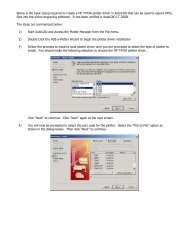
Select Start… Run… from the toolbar on the Windows desktop.
16 <strong>Vision</strong> Software User's Guide<br />
Type the location of the CD drive followed by “:\setup.exe” in the command<br />
line.<br />
Click on OK.<br />
The installation process will now begin.
Chapter 2 - Installing <strong>Vision</strong> 17<br />
Select <strong>Vision</strong> <strong>Engraving</strong> Software and click Next.<br />
Note: You can install a demo version of <strong>Vision</strong> Pro or <strong>Vision</strong> Pro Scan at a<br />
later time if you would like. This will allow you to evaluate the <strong>Vision</strong> Pro<br />
& <strong>Vision</strong> Pro Scan programs.<br />
The <strong>Vision</strong> Software installation will now continue.
18 <strong>Vision</strong> Software User's Guide<br />
The welcome screen will now appear. Click on Next.
Chapter 2 - Installing <strong>Vision</strong> 19<br />
The <strong>Vision</strong> Software License Agreement will now be shown. In order to<br />
continue the <strong>Vision</strong> Installation, you must click on Accept.<br />
Select a folder or leave the default folder as is and click Next.
20 <strong>Vision</strong> Software User's Guide<br />
Select Complete Installation and click Next<br />
Select the language you would like to install <strong>Vision</strong> in and click Next.
Chapter 2 - Installing <strong>Vision</strong> 21<br />
Select the <strong>Vision</strong> Serial Controller type you have. You can tell by looking<br />
at the front panel of the controller. If it says Series II above the large<br />
emergency stop button than select Series II controller, otherwise select<br />
Series I controller. If you own a VE-810 Engraver, select the VE810<br />
engraver. If you have upgraded a <strong>Vision</strong> Non Serial Controller to a Serial<br />
Controller, select Non Serial Controller Upgrade and click Next.<br />
The <strong>Vision</strong> Software installation will now continue.
22 <strong>Vision</strong> Software User's Guide<br />
Select the system type that you have. Standard <strong>Vision</strong> Machine is a stand<br />
alone flat material engraver. <strong>Vision</strong> Combo Machine is if you have a stand<br />
alone flat material engraver and a Cylindrical engraver. Click Next when<br />
finished.
Select the type of system you have and click Next.<br />
Chapter 2 - Installing <strong>Vision</strong> 23
24 <strong>Vision</strong> Software User's Guide<br />
Select a Program Group Name or leave it as it is and select Finish.<br />
The software installation is now complete. Select OK<br />
To run the <strong>Vision</strong> software, select the <strong>Vision</strong> icon from the desktop or from<br />
the Start Menu - Programs - <strong>Vision</strong> <strong>Engraving</strong> Software group.<br />
Copying Logos, Fonts & Jobs from a<br />
disk<br />
There are times when you may have a <strong>Vision</strong> Logo, Font or Job on a<br />
diskette that you would like to copy to your computer’s hard drive. This<br />
commonly happens if you purchase a logo or font from a company that<br />
makes logos for you. To copy the file from a diskette to the hard drive,<br />
follow these steps.<br />
Note: It is recommended that you do not run <strong>Vision</strong> logos, fonts or jobs off<br />
of a floppy disk
Chapter 2 - Installing <strong>Vision</strong> 25<br />
1. Put your floppy disk into your computer’s disk drive. This is usually<br />
drive A.<br />
2. Using the mouse, RIGHT click on the Start button in the lower left hand<br />
corner of your Windows Desktop.<br />
3. The following menu will appear. LEFT mouse click on Explore<br />
4. You will see a screen like the one below.
26 <strong>Vision</strong> Software User's Guide<br />
5. Press the Page Up button on your keyboard 3 or 4 times until you see the<br />
words 3 1/2 Floppy (A:). LEFT mouse click on 3 1/2 Floppy (A:). Your<br />
screen should look like the following (except the file names will be the name<br />
of your logo, font or job names).
Chapter 2 - Installing <strong>Vision</strong> 27<br />
6. Single LEFT mouse click on the file name in the right side of your screen<br />
that you would like to copy to the hard drive. Note: You can select more<br />
than one file by holding the CTRL key down on the keyboard when you<br />
LEFT mouse click on the file name.<br />
7. Go to the Edit Menu and then to Copy.
28 <strong>Vision</strong> Software User's Guide<br />
8. Scroll down the folder list until you see the Viswin Folder. Double click<br />
on the Viswin folder. Your screen should look like the following.<br />
9. If you are copying a <strong>Vision</strong> font, LEFT mouse click on the Fonts folder<br />
under Viswin. If you are copying a <strong>Vision</strong> Job, LEFT mouse click on the<br />
Jobs folder under Viswin. If you are copying a <strong>Vision</strong> Logo, LEFT mouse<br />
click on the Logos folder under Viswin. The Fonts, Jobs or Logos folder<br />
will now be highlighted like below.
10. Go to the Edit Menu and then to Paste.<br />
Chapter 2 - Installing <strong>Vision</strong> 29<br />
Your <strong>Vision</strong> Logo, Font or Job is now copied to your hard drive.
30 <strong>Vision</strong> Software User's Guide<br />
Chapter 3 - Using <strong>Vision</strong> -<br />
The Basics<br />
Terminology<br />
To begin, you should learn some of the common terms used in this manual.<br />
When using a mouse, you will see a mouse pointer on the screen (usually an<br />
arrow). This pointer is a visual indicator of screen locations. To move the<br />
pointer, you move the mouse. The following terms relate to using a mouse.<br />
Point Move the pointer to “point” at something on the<br />
screen.<br />
Click Press and release the left button on the mouse.<br />
Right Click Press and release the right button on the mouse.<br />
Double-Click Press and release the left button on the mouse two<br />
times rapidly.<br />
Drag Point at an object and press and hold down the left<br />
button. While holding down the button, move the<br />
mouse which in turn will “drag” the object. When<br />
you let go of the button, the object will be “dropped”<br />
at that position.
Chapter 3 - Using <strong>Vision</strong> - The Basics 31<br />
Select Point and click on an object so the object becomes<br />
active - the object will generally be highlighted in<br />
some way to show that it is currently selected.<br />
Starting <strong>Vision</strong><br />
To start <strong>VISION</strong>, click on the icon that is labeled “<strong>Vision</strong>” on your<br />
Windows desktop. (You can also start <strong>VISION</strong> by selecting “<strong>Vision</strong>” from<br />
the <strong>Vision</strong> <strong>Engraving</strong> Software program group as in figure below.)<br />
<strong>VISION</strong> will now go through a system check and then load all the available<br />
default fonts. You will see the mouse pointer (an arrow) and <strong>Vision</strong>’s main<br />
screen.
32 <strong>Vision</strong> Software User's Guide<br />
Intro Screen<br />
This is the first screen you will see. It contains four areas, which<br />
are described as follows:<br />
A. Windows Reference Line<br />
B. Menu select line.<br />
C. Toolbar<br />
D. Blank Work area.<br />
E. Device status area.<br />
A. Windows reference line<br />
The Windows reference line has the <strong>Vision</strong> minimize, maximize<br />
and close selections. It also has the <strong>VISION</strong> software version<br />
number.
Chapter 3 - Using <strong>Vision</strong> - The Basics 33<br />
Be sure to note the <strong>VISION</strong> version number at the left side of the<br />
line. When calling for software support you will be required to<br />
provide this version number as well as your software protection<br />
key serial number.<br />
B. Menu select line<br />
The name of each menu describes its contents. For example, all<br />
operations to do with files and jobs are listed under the FILE<br />
menu.<br />
C. Toolbar<br />
To select a menu, either position the mouse on the desired menu<br />
and click the left button, or hold down the ALT key and press the<br />
capital letter in the menu name. For example, to open the file<br />
menu by keyboard, hold down the Alt key and press F.<br />
You will notice as you open these menus that some of the<br />
functions are grayed out and that you cannot select them. They<br />
are designed to only work when there is a job open.<br />
If you have chosen the wrong menu item, either move the mouse<br />
pointer to the correct menu item, click and it will open, or press<br />
the escape key once and then press the letter that represents the<br />
option.<br />
A list of options will appear under each main heading. To select<br />
one of them, you can either point to it with the mouse and click or<br />
you can use the up/down arrow keys to move to the correct line<br />
and press the ENTER key.
34 <strong>Vision</strong> Software User's Guide<br />
This is a common feature in Windows programs. Clicking the<br />
different icons will give you different results. Each icon is<br />
explained below.<br />
Clicking this icon will create a new blank job. It works the same<br />
as going to the file menu and then to new job.<br />
Clicking this icon will bring you to the load job screen.<br />
Clicking this icon will bring you to the save job screen.<br />
Clicking this icon will bring you to the font load screen.<br />
Clicking this icon will bring you to the graphical print screen.<br />
Clicking this icon will bring you to the graphic display screen.<br />
Clicking this icon will bring up the <strong>Vision</strong> help file.
Chapter 3 - Using <strong>Vision</strong> - The Basics 35<br />
D. Blank work area<br />
This is the area that will contain the details of your job when you<br />
open, load or create a new job.<br />
E. Device status area<br />
This area will show you the status of your <strong>Vision</strong> controller. If the<br />
controller is on and connected properly to the computer, it will<br />
read “Phoenix: Waiting”. At this point, you can send a job to the<br />
<strong>Vision</strong> controller. When there is no communication between the<br />
<strong>Vision</strong> control unit and the computer, the status line will read<br />
“Phoenix: Offline” or “Phoenix: Busy. Other messages could<br />
include, i.e. ”Phoenix: Busy R2“ when the machine is busy<br />
engraving a repeat job, with ”R2“ being repeat number 2.<br />
Creating a simple job<br />
With the intro screen showing, click on the File Menu and then New Job.<br />
You have now created a new blank job. Click on the Plate Menu and then<br />
Autoplate. You should have a screen that looks like the following:
36 <strong>Vision</strong> Software User's Guide<br />
Type in 3 for the Plate Width, 1.25 for the Plate Height and 2 for the<br />
Number of lines. The screen should now look like this:
Chapter 3 - Using <strong>Vision</strong> - The Basics 37<br />
Click on the Height for the second line and change it to .2. Your screen<br />
should look like this:
38 <strong>Vision</strong> Software User's Guide<br />
Click on the Okay button. You will now be taken to the Main screen where<br />
you can enter the text for the plate.
Chapter 3 - Using <strong>Vision</strong> - The Basics 39<br />
Type the name John Smith and then press the [Enter] key on your keyboard.<br />
The cursor will move to the second line. Type the word ABC Company.<br />
You have now created a simple 2-line nametag. Press the [F8] key on your<br />
keyboard to get a graphical view of the plate. Click on the Okay button to<br />
bring <strong>Vision</strong> back to the main screen. Let’s save this job for future<br />
reference.<br />
To save a job, go to the File Menu and then to Save Job. Type in SIMPLE<br />
for the job name and click on OK. The job is now saved.
40 <strong>Vision</strong> Software User's Guide
Chapter 3 - Using <strong>Vision</strong> - The Basics 41
42 <strong>Vision</strong> Software User's Guide<br />
Chapter 4 - The <strong>Vision</strong><br />
Menus<br />
Main Screen<br />
Material Type: This feature will allow you to set the maximum engraver<br />
speed to specific material types. The space bar will toggle through the<br />
different material types.<br />
Note: To add different material types or change the material types, you can<br />
edit the material.sys file. To do this, go the Windows Start Menu and click
Chapter 4 - The <strong>Vision</strong> Menus 43<br />
on Programs, <strong>Vision</strong> <strong>Engraving</strong> Software and Edit Material Types. You can<br />
change the Number of material entries to whatever you would like. Then,<br />
you can change the XY Maximum cut speed to a number between 1 and 30<br />
and the Z maximum penetrate speed to a number between 1 and 20. The<br />
higher the number, the faster the maximum speed will be at the engraver.<br />
When you are finished changing the values, go to the File Menu and then<br />
Save. Once the file is changed, you must exit <strong>Vision</strong> and then enter back<br />
into <strong>Vision</strong> for the change to take effect. The maximum speed will be<br />
limited to the maximum allowable speed that is set in the <strong>Vision</strong> Serial<br />
Controller.<br />
Condense Mode: The space bar will toggle through the different<br />
condensing choices. See Condense Mode for more information on this<br />
feature.<br />
Plate Width & Height: You can enter the plate width & height in here.<br />
Plate 1 of 1: This displays the current plate number you are on and how<br />
many plates are in the current job. You can move between plates by<br />
clicking the up or down arrow to the right or by holding down the <br />
key and pressing or .<br />
Line 1 of 1: This displays the current line number you are on and how many<br />
lines are on your plate. You can move between lines by clicking the up or<br />
down arrow to the right or by pressing or .<br />
Subline 0 of 0: This displays how many sublines you have on your line of<br />
text and which one you are currently on. You can move between sublines<br />
by clicking the up or down arrow to the right. See Insert Subline for more<br />
information on this feature.<br />
Text: This is where the text for the plate is entered. If you have more than<br />
one line of text, pressing the key will move you down line by line.<br />
The up and down arrows will also move the cursor up and down line by line.
44 <strong>Vision</strong> Software User's Guide<br />
Line Height: This is the letter height of the current line. You can change<br />
this by clicking on it with the mouse and then changing the value.<br />
Baseline: This is the distance from the top of the plate to the bottom of the<br />
current line.<br />
Left margin: This is the distance from the left side of the plate to the left<br />
edge of the current line.<br />
Note: The text will only extend to the left margin if there is enough text to<br />
expand it to there.<br />
Right margin: This is the distance from the right side of the plate to the<br />
right edge of the current line. Note: The text will only extend to the right<br />
margin if there is enough text to expand it to there.<br />
Font style: This is the font style of the current line. Pressing the space bar<br />
toggles through the loaded fonts. Hint: Holding down the shift key while<br />
pressing the space bar will toggle through the fonts in the reverse order. See<br />
Font Load to load additional fonts. Note: To change the default fonts that<br />
<strong>Vision</strong> comes up with, you can edit the cipfont.sys file. To do this, go the<br />
Windows Start Menu and click on Programs, <strong>Vision</strong> <strong>Engraving</strong> Software<br />
and Edit Default Fonts. This will bring up the Windows Notepad with a file<br />
called cipfont.sys. You can change the order of the fonts or add any of the<br />
available <strong>Vision</strong> fonts into this list. The first font name will be the one that<br />
<strong>Vision</strong> defaults to. You must add the .cff extension to the end of the font<br />
name. Once you have finished changing the font names, go to the File menu<br />
and then Save. Once the file is changed, you must exit <strong>Vision</strong> and then<br />
enter back into <strong>Vision</strong> for the changes to take effect.<br />
Text length: This displays how long the current line is. You can change<br />
this number to expand or condense the text.<br />
Justification: This is how the text will be placed on the line. There are<br />
three choices for justification. Centered - This will center the text from left
Chapter 4 - The <strong>Vision</strong> Menus 45<br />
to right between the left and right margins. Left - This will move the text to<br />
the left margin. Right - This will move the text to the right margin. The<br />
space bar will toggle through the types of justification. Hint: Holding down<br />
the shift key while pressing the space bar will toggle through the choices in<br />
the reverse order.<br />
Condensation: This shows how wide the current line is in a percentage<br />
form. 100% is a standard text width. If this number is 80%, the text will be<br />
condensed to 80% of the standard width. If this number is 120%, the text<br />
will be expanded to 120% of the standard width.<br />
Inter char space: This shows how wide the current spacing between each<br />
letter is. The standard inter character space is 100%. If this number is 80%,<br />
the inter character space will be condensed to 80% of the standard inter<br />
character space. If this number is 120%, the text will be expanded to 120%<br />
of the standard inter character space.<br />
Italicization: This allows you to italicize or slant your text to the left or<br />
right. If you type a positive number in, the text will slant to the right by the<br />
amount of degrees entered. If you type a negative number in, the text will<br />
slant to the left by the amount of degrees entered.
46 <strong>Vision</strong> Software User's Guide<br />
File Menu<br />
New Job<br />
This feature creates an empty job in the main <strong>VISION</strong> screen using the<br />
defaults defined in the installation of <strong>VISION</strong>. These defaults can be<br />
changed using the System Preferences option in <strong>VISION</strong>.<br />
<strong>VISION</strong> is capable of having up to eight (8) jobs open at one time. The<br />
New job selection will not be accessible when eight (8) jobs are already<br />
open.
Load Job<br />
Chapter 4 - The <strong>Vision</strong> Menus 47<br />
This feature allows you to open a previously saved job. Selecting this<br />
feature brings up the Load Layout window.<br />
Note: If your job is on a floppy disk, it is recommended that you copy it to<br />
your computer’s hard drive first. Click here for instructions on how to do<br />
this.
48 <strong>Vision</strong> Software User's Guide<br />
You may either, type the filename and click OK, or you can select the<br />
name of the job with the mouse pointer and click OK.<br />
Note: If you use the pointer to click on the job name, the Comments field<br />
will display any comments that you might have saved with the job.<br />
There are two choices of Load Layout that you can choose from:<br />
Complete details or Dimensions Only. This is selected in the format box.<br />
Complete details will load the entire job that was saved including all of<br />
the text in the job.<br />
Details Only will load the entire job except for text that was in that job.
Chapter 4 - The <strong>Vision</strong> Menus 49<br />
Note: <strong>Vision</strong> defaults the Job Load and Job Save directories to your hard<br />
drive C and in a directory called \Viswin\Jobs. If you would like to change<br />
the default Job Load and Job Save directory, you must do the following.<br />
Go to the Windows Start Menu, then to Programs, then to <strong>Vision</strong><br />
<strong>Engraving</strong> Software and click on Edit <strong>Vision</strong> defaults. This will bring up<br />
the Cipher.sys file into the Windows Notepad. Go to the section in the file<br />
that says Default Job Load Directory and change it from C:\VisWin\Jobs to<br />
the drive and directory that you installed <strong>Vision</strong> into. You will also need to<br />
change the Default Save Directory.<br />
Save Job<br />
This feature allows you to save a job to your computers hard drive or to a<br />
floppy disk. Selecting this function brings up the Save Layout window.
50 <strong>Vision</strong> Software User's Guide<br />
You will need to type the filename and click OK. If you would like, you can<br />
enter in any job comments that you would like saved with the job in the<br />
Comments field. A typical item entered into the comments field is the cutter<br />
size that was required for the job you are saving.<br />
There are two choices of Save Layout that you can choose: Complete<br />
details or Dimensions Only. This is selected in the format box. Complete<br />
details is the default; to select Dimensions Only, click on the down arrow to<br />
the right of the box.<br />
Complete details will save the entire job that was created including all of<br />
the text in the job.<br />
Dimensions Only will save the entire job except for any text that was in that<br />
job.
Chapter 4 - The <strong>Vision</strong> Menus 51<br />
Note: <strong>Vision</strong> defaults the Job Load and Job Save directories to your hard<br />
drive C and in a directory called \Viswin\Jobs. If you would like to change<br />
the default Job Load and Job Save directory, you must do the following. Go<br />
to the Windows Start Menu, then to Programs, then to <strong>Vision</strong> <strong>Engraving</strong><br />
Software and click on Edit <strong>Vision</strong> defaults. This will bring up the<br />
Cipher.sys file into the Windows Notepad. Go to the section in the file that<br />
says Default Job Load Directory and change it from C:\VisWin\Jobs to the<br />
drive and directory that you installed <strong>Vision</strong> into. You will also need to<br />
change the Default Save Directory.<br />
Import Job<br />
This feature allow you to import a job created in the Dahlgren Superpro<br />
program. Selecting this feature brings up the Import Job Layout window.<br />
Note: If your job is on a floppy disk, it is recommended that you copy it to<br />
your computer’s hard drive first. Click here for instructions on how to do<br />
this.<br />
Note: <strong>Vision</strong> defaults the Dahlgren Superpro jobs into your hard drive C<br />
and in a directory called \Viswin\SpJobs. If you would like to change the<br />
default job import folder, you must do the following. Go to the Windows<br />
Start Menu, then to Programs, then to <strong>Vision</strong> <strong>Engraving</strong> Software and click
52 <strong>Vision</strong> Software User's Guide<br />
on Edit <strong>Vision</strong> defaults. This will bring up the Cipher.sys file into the<br />
Windows Notepad. Go to the section in the file that says Default import<br />
job directory and change it from C:\VisWin\SpJobs to the drive and<br />
directory that you installed <strong>Vision</strong> into.<br />
You may either, type the filename and click OK, or you can select the<br />
name of the job with the mouse pointer and click OK.<br />
There are three choices that you can choose under the format field. The<br />
choices are Superpro 3.50, Superpro 3.12, and Superpro 3.02. You<br />
must select the correct version of Superpro that the jobs were created in. If<br />
you try to load the job using the incorrect type, the following error message<br />
will appear:
Chapter 4 - The <strong>Vision</strong> Menus 53<br />
When importing Dahlgren Superpro jobs, you must configure <strong>Vision</strong> to tell<br />
it which fonts are setup in the Superpro jobs. To do this, you must edit a<br />
file called Dahl2cip.sys in the Viswin folder. You can open this folder<br />
with Windows Notepad. Once it is open, the screen will look like the<br />
following:<br />
If you are importing jobs from Superpro version 3.02, you must edit the<br />
numbers in lines 2 through 9 in the screen above to map out the fonts that<br />
are in your Dahlgren control unit. The first 0 in the file above correlates to<br />
the Dahlgren font 0. Typically, this is the utility font. So, the number that<br />
you would enter for that line would be the <strong>Vision</strong> font number that<br />
correlates to Utility. Since the default <strong>Vision</strong> fonts are 1- Gothic, 2 - 3 line<br />
Roman, 3 - 3 line helvetica, 4 - Century & 5 - Utility, you would enter 5 to<br />
match Utility. Typically, the next font in a Dahlgren control unit is Gothic.<br />
So, the number you would enter for the next line is 1, which matches the<br />
<strong>Vision</strong> Gothic font. You would change the numbers in this file until you<br />
have matched all of the fonts in the Dahlgren control unit.
54 <strong>Vision</strong> Software User's Guide<br />
If you are importing jobs from Superpro versions 3.12 or 3.50, you must<br />
edit lines 11 and higher. You must change the name of the Dahlgren font,<br />
including the .ft9 extension to match the font that you have in the Dahlgren<br />
software. You must then change the number to the right of the font to<br />
correlate it to the <strong>Vision</strong> font number, which is explained in the paragraph<br />
above.<br />
Note: If a font in a Dahlgren job is not mapped, it will default to the <strong>Vision</strong><br />
Gothic font.<br />
Print Job<br />
Print Job Details<br />
This feature will print the job specifications to a printer or text file. Such<br />
specifications include the plate size, letter heights, text, borders etc. of the<br />
job. If you select this option, it will bring up the Print Layout window,<br />
shown below.<br />
The Printer box displays which printer you will be printing to.
Chapter 4 - The <strong>Vision</strong> Menus 55<br />
The Print range box allows you to either print the entire layout to your<br />
printer or just certain plates to your printer if you have a multiple plate job.<br />
The No. Of Copies allows you to print multiple copies to your printer.<br />
The Print quality allows you to change the print resolution. You can select<br />
from high, medium, low or draft.<br />
Print to file will send the job to a disk file instead of the printer.<br />
Print Options:<br />
If you select Job details, <strong>Vision</strong> will output every parameter of the job to a<br />
text file or printer.<br />
If you select Text only, <strong>Vision</strong> will output only the text of the job to a text<br />
file or printer.<br />
You can print more than one copy of this file to the printer by changing the<br />
No. of copies.<br />
Setup will allow you to change the printer that you are printing to and also<br />
allow you to change the printer defaults.<br />
Note: The Print Job Details feature supports almost all Windows compatible<br />
printers including network printers. In order to use this feature, the printer<br />
must be installed correctly in Windows. See your Windows manual for<br />
instructions on installing a printer.<br />
Note: Some earlier versions of <strong>Vision</strong> did not support all Windows<br />
compatible printers. If your version does not print job details, please check<br />
with your local distributor or with <strong>Vision</strong> <strong>Engraving</strong> <strong>Systems</strong> to get an<br />
updated version of <strong>Vision</strong>.
56 <strong>Vision</strong> Software User's Guide<br />
Graphical Print<br />
This feature will print an actual copy of the layout to your printer. It will<br />
bring up the Graphical Print Window as shown below.<br />
Note: The ”Hot Key“ for this feature is F3. By pressing the F3 key, <strong>Vision</strong><br />
will automatically bring up the Graphical Print screen.<br />
The Printer box displays which printer you will be printing to.<br />
The Print range box allows you to either print the entire layout to your<br />
printer or just certain plates to your printer if you have a multiple plate job.<br />
The No. Of Copies allows you to print multiple copies to your printer.<br />
The Print quality allows you to change the print resolution. You can select<br />
from high, medium, low or draft.
Chapter 4 - The <strong>Vision</strong> Menus 57<br />
Page control allows you to center your job on the paper if you have them<br />
selected.<br />
Fit to Page will expand or shrink the job to fit on one sheet of paper.<br />
Print to file will send the job to a disk file instead of the printer.<br />
Setup will allow you to change the printer that you are printing to and also<br />
allow you to change the printer defaults.<br />
Note: The Graphical Print feature supports almost all Windows compatible<br />
printers including network printers. In order to use this feature, the printer<br />
must be installed correctly in Windows. See your Windows manual for<br />
instructions on installing a printer.<br />
Engrave<br />
This feature will send the job to the engraver to be engraved.
58 <strong>Vision</strong> Software User's Guide<br />
Note: The ”Hot Key“ for this feature is F9. By pressing the F9 key, <strong>Vision</strong><br />
will automatically bring up the Execute Layout screen shown below.<br />
Scale Axis: This will increase or decrease the size of the engraved job when<br />
it is sent to the engraver. For example, if you select .5 X and .5 Y, it will<br />
engrave the job at one half of the size that it was created at.<br />
Offsets: This will move the job to be engraved to the right or down the<br />
specified amount.
Chapter 4 - The <strong>Vision</strong> Menus 59<br />
Ignore clips: If this is selected, the engraver will try to engrave a job even if<br />
it is off of the plate. If it is not selected, the engraver will ”clip“ or cut off<br />
anything that is outside of the plate.<br />
Note: This command can be used to ensure that items such as<br />
cutout borders are engraved completely when they are extended out to the<br />
edge of your engraving table. Sometimes the software will cut off or clip<br />
parts of your engraving if it is close to the edge of the table and this will<br />
allow you to not have the problem.<br />
Diameter: This will only be highlighted if you are using a rotary machine<br />
such as the <strong>Vision</strong> Cylindrical Engraver. It is used to enter the diameter of<br />
the object you are engraving.<br />
Write to HPGL plot file: This will send the job to your hard drive instead<br />
of the engraver. This will create a standard HPGL plotter file. You can use<br />
this option if you would like to create a file that you can import into another<br />
program such as CorelDraw. The file will have a .PLT extension.<br />
Driver Select: This will determine which machine the job will be sent to.<br />
By clicking the down arrow to the right of the driver name (Phx.cdf), you<br />
can change to other machine types.<br />
Plate Cut Out: This is used to cut the plate out after you engrave it. By<br />
typing a number in, you can increase the distance between the edge of the<br />
plate and the cut mark.<br />
Spindle Motor Control: This feature is used only with the VE-810<br />
Engraver. It is used to turn the spindle motor on or off while engraving.<br />
You select the type you would like, either Rotary Engrave or Diamond<br />
Drag.<br />
Note: If you click on OK from this screen and get an error message that<br />
looks like the following, please see the Appendix B - Troubleshooting<br />
section of this manual.
60 <strong>Vision</strong> Software User's Guide<br />
Close Job<br />
This feature will close the job that you are currently working on. If you<br />
have not saved the job, <strong>Vision</strong> will give you a message like the one below:
Chapter 4 - The <strong>Vision</strong> Menus 61<br />
This will let you know that the job will be lost unless it is saved.<br />
Note: You can also close a job by clicking on the X in the upper right<br />
corner of the job window.<br />
Flush Job<br />
This feature is used to erase either the entire layout or all of the text from the<br />
layout.
62 <strong>Vision</strong> Software User's Guide<br />
If you select Clear all lines from layout, <strong>Vision</strong> will erase the whole job<br />
and let you start a new one.<br />
If you select Clear all text from layout, <strong>Vision</strong> will erase only the text from<br />
the existing job.<br />
Line 1 to 1: This allows you to select the range of lines that the text will be<br />
removed from.<br />
If your job consists of multiple plates, the screen will look like the<br />
following:
Chapter 4 - The <strong>Vision</strong> Menus 63<br />
Plate 1 to 1: This allows you to select the range of plates that the text will<br />
be removed from.<br />
Exit
64 <strong>Vision</strong> Software User's Guide<br />
This feature will exit you out of the <strong>Vision</strong> program. If you have not saved<br />
the job, <strong>Vision</strong> will display a message like the one below:<br />
This will let you know that the job will be lost unless it is saved.<br />
Note: You can also exit <strong>Vision</strong> by clicking on the X in the upper right<br />
corner of the screen.<br />
Edit Menu<br />
Clipboard Paste<br />
This feature will insert any text that is in the Windows Clipboard into the<br />
text area on the main screen of <strong>Vision</strong>. Text is put into the Windows<br />
Clipboard from almost any program by selecting Copy from the Edit menu.<br />
Note: The ”Hot Key“ for this feature is [shift] & [insert]. By pressing the<br />
[shift] & [insert] keys at the same time, <strong>Vision</strong> will automatically paste any<br />
text from the Windows Clipboard into the text area.
Copy<br />
Chapter 4 - The <strong>Vision</strong> Menus 65<br />
This feature will Copy or store the information from the current line of text<br />
and allow you to Paste the information to another line of text. It will bring<br />
up the Details to Copy window as shown below.<br />
Note: Using this feature will replace any text that was previously placed on<br />
the <strong>Vision</strong> clipboard or the Windows clipboard.<br />
You can select the Details To Use by clicking on any of the specifications<br />
from the list on the left. You can select all of the details from a line by
66 <strong>Vision</strong> Software User's Guide<br />
clicking on the Select All Icon. The Clear Icon will erase all of the<br />
selections chosen.<br />
The Values column to the right shows you the information that is associated<br />
with the line you want to copy from.<br />
Paste<br />
This feature will Paste the information that was Copied to a line or group<br />
of lines.<br />
There are three selections that you can choose from:<br />
1) Current Line: This feature will ”Paste“ the information that was<br />
”Copied“ to the current line that you are on.<br />
2) Multiple Lines: This feature will ”Paste“ the information that was<br />
”Copied“ to multiple lines. You can select the line you want to paste from
Chapter 4 - The <strong>Vision</strong> Menus 67<br />
and to by entering the line numbers in the Start Paste At Line and Finish<br />
Paste On Line section.<br />
3) All Lines: This feature will ”Paste“ the information that was ”Copied“ to<br />
all of the lines on your plate.<br />
Note: This feature is very useful if you have created a layout with many<br />
lines and you would like to change the font on many lines at one time. You<br />
can change the first line’s font and ”Copy“ it and then ”Paste“ that font to<br />
the rest of the lines on your job.<br />
Text Menu<br />
Load Logo<br />
This feature will load a logo file into the <strong>Vision</strong> program and allow you to<br />
engrave it.<br />
Note: If your logo is on a floppy disk, it is recommended that you copy it<br />
to your computer’s hard drive first.
68 <strong>Vision</strong> Software User's Guide<br />
There are eight types of logos that can be loaded into <strong>Vision</strong>. The type of<br />
logo you want to load can be changed by clicking on the arrow to the right<br />
of the Format: box.<br />
1) Plotter file: This file type is a standard HPGL plotter file. Most CAD<br />
programs can output to this type of file. The file extension that is supported<br />
is .PLT.<br />
2) DesignCad DC2: This file type is created in a program called Design<br />
Cad. It is the standard Design Cad file. The file extension is .DC2.<br />
Note: This will only work with Design Cad if you save the file as a DC2<br />
file. It will not read the DW2 file extension.
Chapter 4 - The <strong>Vision</strong> Menus 69<br />
3) Casmate SCA file: This file type is created in some of Scanvec’s<br />
programs, such as Casmate or Enroute. This file must be exported from<br />
Casmate or Enroute, not just the saved file. This feature can import 3D files<br />
created in these programs as well as 2D files. The file extension is .SCA.<br />
4) PhotoEngrave PCX (line): This file type is created in almost any<br />
Windows graphics package. It takes a picture file and will engrave it as a<br />
group of lines. The file extension is .PCX.<br />
Guide to using PhotoEngrave:<br />
a) The file must be at a 256 colors or less.<br />
b) Best results come from 256 color or 256 grayscale images.<br />
Colored images are internally changed into grayscales before<br />
photoengraving and give no better results.<br />
c) The photoengrave process assumes that the top color to be cut is<br />
light (white) and the lower color is dark. If the material is dark on<br />
top and light below, you must make a negative PCX file image.<br />
d) Each line of the image becomes a cutter line and as a guide, the<br />
cutter should be 8% of the distance between the cut lines.<br />
Although this will vary slightly depending on the color differential<br />
between the top and substrate colors but for white on black, 8% is<br />
the desired cutter width.<br />
e) Due to the limitations of grinding a fine tip on a cutter, this<br />
means that the smallest spacing practical between cuts is about .01<br />
inches, but as a general guide to start with is .020 apart.<br />
f) The above means that it is best to know the size of the final work<br />
before preparing the PCX image file. The aim is to scan and/or<br />
scale the image down to the required resolution. For a .020 cut<br />
spacing on a 4 inch x 6 inch wide images, the PCX image<br />
resolution would need to be 200 x 300 pixels.<br />
g) The time to cut a PCX file varies greatly not only on size, but on<br />
the color content. White across will cut much faster than dark<br />
areas. It is recommended that you look at the estimated time to<br />
complete a job when pricing it out.<br />
h) The technique of photoengraving tricks the eye into inducing<br />
color variation by area, which is part of the way the human eye
70 <strong>Vision</strong> Software User's Guide<br />
works. Unfortunately the technique differs from reflected light<br />
(paper or your engraving) and transmitted light (your crt monitor)<br />
and is affected by scaling. Thus can not be accurately represented<br />
on the graphics view (F8) screen.<br />
i) Initially on the first few lines, the image will always look like it<br />
hasn’t worked or is too light or too dark, but wait until you get<br />
further because of the eye trick you need a reasonable amount of<br />
area to judge.<br />
j) If using a nose cone, you must not adjust the depth of the cut<br />
while it is in the middle of the photoengrave. This will cause you<br />
to see a change in darkness.<br />
Troubleshooting PhotoEngrave<br />
Problem: My image is solid black.<br />
Solution: Check that your PCX file is 256 colors or less. If<br />
your PCX file is too high a resolution for your cutter width, reduce<br />
the resolution or decrease the PCX file size.<br />
Problem: The image is very clear but it is too light.<br />
Solution:<br />
wider cutter.<br />
Increase the PCX file pixel resolution or use a<br />
5) PhotoEngrave PCX (dots): This file type is created in almost any<br />
Windows graphics package. It takes a picture file and will engrave it as<br />
groups of dots. The file extension is .PCX. Use the same guidelines as<br />
above for this feature.<br />
6) AutoCAD DXF file: This file type is created in the AutoCAD program.<br />
The file extension is .DXF.<br />
7) BMP Raster (Laser): This file type is used only for outputting to a laser<br />
engraver. At this time, this function is not completed and does not work<br />
properly. The file extension is .bmp.
Chapter 4 - The <strong>Vision</strong> Menus 71<br />
8)) G-Code ascii: This file type is used for importing G-Code files. There<br />
are many types and variations of G-Code and only simple G-Code<br />
commands are imported with this feature. The file extension is .nc.<br />
Note: Once you have selected the file type and file name and click OK, you<br />
MUST type a capital letter A in the text area to represent the logo. If you<br />
do not type a capital letter A in the text area, no logo will engrave.<br />
Once you load the logo that you would like to use, it will appear in the font<br />
style area of the main <strong>Vision</strong> screen. You can use the space bar to ”toggle“<br />
through the different loaded logos and fonts.
72 <strong>Vision</strong> Software User's Guide<br />
Font Load<br />
This feature will allow you to select the font that you would like to use on<br />
your layout.<br />
Note: If your font is on a floppy disk, it is recommended that you copy it to<br />
your computer’s hard drive first.
Chapter 4 - The <strong>Vision</strong> Menus 73<br />
There are two types of fonts that can be loaded into <strong>Vision</strong>. The type of font<br />
you want to load can be changed by clicking on the arrow to the right of the<br />
Format: box.<br />
1) <strong>Vision</strong> CFF font: This is a standard <strong>Vision</strong> font. The file extension is<br />
.CFF.<br />
2) Dahlgren FT9 font: This is a font from Dahlgren SuperPro Software.<br />
The file extension is .FT9.<br />
Once you load the font that you would like to use, it will appear in the font<br />
style area of the main <strong>Vision</strong> screen. You can use the space bar to ”toggle“<br />
through the different loaded fonts.
74 <strong>Vision</strong> Software User's Guide<br />
Translate to Braille
Chapter 4 - The <strong>Vision</strong> Menus 75<br />
This feature will change the current line of text into Grade II Braille. It<br />
will translate the text, change the font to the Braille font and change the<br />
letter height to the standard Braille letter height.<br />
Note: The standard Braille font included with <strong>Vision</strong> creates the routed<br />
out Braille. If you would like to engrave the Braille dot font, you must load<br />
the braille_dot font.<br />
Translate to Bar Code<br />
This feature will change the current line of text into Bar Code. It will<br />
translate the text and change the font to the bar code font.
76 <strong>Vision</strong> Software User's Guide<br />
Insert Subline<br />
This feature will allow you to change line information in the middle of a<br />
line. It can be used for changing the letter height or font in the middle of a<br />
line.<br />
Type in the text you would like and then move the cursor to the middle of<br />
the line by using the keyboard arrows. Move it to where you would like the<br />
change to be and go to Ins Subline. You will see a special character appear<br />
in yout text area that looks like this: §. Next, move the cursor left or right to<br />
the part you would like to change. Once there, you can change the font,<br />
letter height, baseline, italic or any other parameter.
Delete Subline<br />
Chapter 4 - The <strong>Vision</strong> Menus 77<br />
This feature will allow you to delete a subline from your text.<br />
Move the cursor to the subline area you would like to delete and goto Del<br />
Subline. This will delete it.<br />
Change Case<br />
To Upper<br />
This feature will change all of the text on the current line to upper case.
78 <strong>Vision</strong> Software User's Guide<br />
To Lower<br />
This feature will change all of the text on the current line to lower case.<br />
First Word<br />
This feature will change the first letter of the first word on the current line to<br />
upper case.<br />
Each Word<br />
This feature will change the first letter in each word on the current line to<br />
upper case.
Pause Point<br />
Chapter 4 - The <strong>Vision</strong> Menus 79<br />
This feature allows you to program a cutter pause anywhere in your job.<br />
Move the cursor to the place that you would like the engraver to pause and<br />
go to Pause point. You will see a symbol like the following: . When the<br />
engraver gets to this point, it will stop and wait for you to press the start<br />
button on the controller to restart it.<br />
Note: This is useful if you need to change cutters in the middle of your job.
80 <strong>Vision</strong> Software User's Guide<br />
Merge Text<br />
This feature is used to import a standard text file into <strong>Vision</strong>.<br />
The text file can be created in many programs and exported with any file<br />
extension; however, it is easiest if the file has a .TXT extension. The text<br />
file must be set up so that each line of text you would like to import is on it’s<br />
own line. See the picture below.
Chapter 4 - The <strong>Vision</strong> Menus 81<br />
You can import the text to a single line or multiple lines easily. If you are<br />
importing to a single line, goto Merge text and select the text file you wish<br />
to import. Next you need to select which line of text on your plate you<br />
would like to import the text to. You do this by entering the line number<br />
into the Merge From Line and Merge To Line and click OK. (The Merge<br />
From and To line will have the same line number)<br />
There are two scenarios of merging text to multiple lines:<br />
The first scenario is if you want to import text to a consecutive group of<br />
lines (such as to lines 3 through 5). To do this, you follow the same steps as<br />
importing to a single line except you would change the Merge From and To<br />
parameters to match the lines on your plate that you want to merge to.<br />
The second scenario is if you want to import text to non-consecutive lines<br />
(such as to line 3 and to line 5). To do this, you must have two text files.<br />
One text file for the text that you want on the first line and a second text file<br />
for the text that you want on the second line. Once you have two text files,<br />
you will follow the same steps as importing to a single line for the first line.
82 <strong>Vision</strong> Software User's Guide<br />
When you are done importing the first line, you simply go back into merge<br />
text and import the text for the second line the same way you would a single<br />
line.<br />
Note: All text merging is normally done after you have created the plates.<br />
This allows you to have a place to merge the text to.<br />
Line Menu<br />
Insert Line<br />
This feature will let you insert a line after the current line that you are on.<br />
Move the cursor to the line that you would like to copy and then goto Ins<br />
line.<br />
The new line will have all of the same parameters of the original line except<br />
the text that was on the original line. The font, letter height, baseline, etc.<br />
will all be the same.
Delete Line<br />
Chapter 4 - The <strong>Vision</strong> Menus 83<br />
This feature will delete the current line. Move the cursor to anywhere in the<br />
line that you would like to delete and goto Del line. The line is now<br />
deleted.<br />
Fixed Arc<br />
This feature will change a normal line of text into an arced line allowing you<br />
to enter all of the parameters.
84 <strong>Vision</strong> Software User's Guide<br />
When determining the parameters for arcing, it is helpful to think of a circle<br />
with the text going around the circle. We need to place the circle on our<br />
plate in a certain area.<br />
X Center: This number will determine where the arc is from left to right on<br />
our plate. It is calculated from the left side of our plate.<br />
Y Center: This number will determine where the arc is from top to bottom<br />
on our plate. It is calculated from the top of our plate.<br />
Note: The X & Y centers are the points of rotation of the arc. If<br />
the wrong numbers are entered, the text can actually be off of the plate.<br />
Arc radius: This number will determine the radius of the arc. The radius is<br />
measured from the center point of the arc (X & Y Center) to the inside of<br />
the text. The larger the number is, the larger the arc will be.<br />
Start angle: This number will determine the degree amount that the arc will<br />
start.
Chapter 4 - The <strong>Vision</strong> Menus 85<br />
End angle: This number will determine the degree amount that the arc will<br />
end.<br />
Zero degrees is at 12 o'clock.<br />
270 or -90 degrees is at 9 o'clock<br />
90 or -270 degrees is at 3 o'clock<br />
180 degrees is at 6 o'clock<br />
If you have an arced line and want the line to be straight again, click on the<br />
clear button and then click on Okay.<br />
The page up and page down keys will move you up and down from line to<br />
line.<br />
Note: If you go into the autoplate feature after you have a line that is arced,<br />
autoplate will erase the arc parameters. You will need to enter the arc<br />
parameters after you are finished using the autoplate feature.<br />
Easy Arc
86 <strong>Vision</strong> Software User's Guide<br />
This feature will change a normal line into an arced line by defining the<br />
margins on your plate.<br />
The only parameters needed to create an easy arc are the margins on the<br />
plate. Enter the top, bottom, left and right margins of your plate and then<br />
select if you want the arc to Bubble Upwards or Bubble Downwards. You<br />
can toggle between the Bubble options by pressing the space bar.<br />
Note: When using the easy arc feature, there is a limitation to what you can<br />
do. For example, when you enter in your margins, the area that you are<br />
allowing the arc to be created in must be at least two times as wide as the<br />
height. If not, <strong>Vision</strong> will show an error message to that effect. You can not<br />
create a 360 degree arc with easy arc. This must be done using the fixed arc<br />
feature.<br />
If you go into the autoplate feature after you have a line that is arced,<br />
autoplate will erase the arc parameters. You will need to enter the arc<br />
parameters after you are finished using the autoplate feature.
Rotation<br />
This feature will allow you to rotate your line.<br />
Chapter 4 - The <strong>Vision</strong> Menus 87
88 <strong>Vision</strong> Software User's Guide<br />
You can select which way you would like to rotate your line by clicking on<br />
the selection you want. If you click on Reverse Engrave, the line will be<br />
reversed. If you know the angle you would like the line to be rotated, you<br />
can enter it in the Specific angle area.<br />
As you make your selection, the F in the box to the right will show you how<br />
the final rotation will be.<br />
The reverse engrave feature is commonly used to invert a logo. For<br />
example, this can be used to make a right handed baseball player left<br />
handed, or make a flower that faces left face right.<br />
Note: This feature will only rotate a line, not the entire plate. If you need to<br />
rotate the entire plate, you must go to the Plate menu and then to Rotation.<br />
Underline<br />
This feature will underline the current line of text. Move the cursor to the<br />
line that you would like to underline and goto the Underline menu from the<br />
Line menu. The Underline Details window opens.
Chapter 4 - The <strong>Vision</strong> Menus 89<br />
Number of cuts: This allows you to make a wider cut for the underline<br />
without changing cutters. If you enter in 3 for the number of cuts, it will go<br />
over the underline 3 times.<br />
Distance between: This allows you to specify how far apart the cuts are.<br />
(Ex. If you enter 3 for the number of cuts and .03 for the Distance between,<br />
you could use a .060 cutter to get an underline that is .18 wide.)<br />
Percent below text: This number will let you choose how far below the text<br />
that the underline will be. The percentage you enter will be that percentage<br />
of the letter size below the line.<br />
Or as a distance: This number will let you choose how far below the text<br />
that the underline will be. The number you enter will be that distance below<br />
the line.<br />
Note: You can use either Percent below text or as a distance. You can’t use<br />
both at the same time. When you type one in, the other is automatically<br />
calculated.<br />
Note: To underline an individual word or letters in a line of text, you must<br />
use the sublines feature. Once the sublines are created, move the cursor
90 <strong>Vision</strong> Software User's Guide<br />
with the arrows to the text section that you would like underlined and then<br />
go to the underline feature.<br />
Edit By Centers<br />
This feature will allow you to move your text or logo on the plate by<br />
changing the center of the object.
Chapter 4 - The <strong>Vision</strong> Menus 91<br />
X Center: This number is how far from the left side of the plate that the<br />
center of your line will be.<br />
Y Center: This number is how far from the top of the plate that the center of<br />
your line will be.<br />
This function can be used to quickly align a number of lines of text by<br />
setting each line’s X Center to the same value.<br />
Note: The ”Hot Key“ for this feature is F2.<br />
Manual Edit<br />
This feature will allow you to change the parameters of each line<br />
individually.
92 <strong>Vision</strong> Software User's Guide<br />
Baseline: This is the distance from the top of the plate to the bottom of the<br />
letter.<br />
Line Ht: This is the height of the letter or logo.<br />
Left: This is the margin of the line from the left side of the plate.<br />
Right: This is the margin of the line from the right side of the plate.<br />
Depth: This is the depth of engraving for the line. This option will only<br />
work properly if you are engraving without a nose cone. If you are using a<br />
nose cone, the depth should be left at 0.000 since the engraving depth is<br />
controlled by the nose cone.<br />
If you enter a depth on this screen, the text will have a blue color on the<br />
Graphical Display.<br />
Note: The ”Hot Key“ for this feature is F4.
Plate Menu<br />
Autoplate<br />
Chapter 4 - The <strong>Vision</strong> Menus 93<br />
This feature is used to create a layout in which <strong>Vision</strong> calculates the spacing<br />
of the layout.
94 <strong>Vision</strong> Software User's Guide<br />
If you enter in the numbers that Autoplate asks for, <strong>Vision</strong> will create the<br />
layout.<br />
Plate Width: The width of the plate.<br />
Plate Height: The height of the plate.<br />
Number of lines: The number of lines on the plate.<br />
From Line Number: Autoplate calculates the spacing for specific lines on<br />
your plate. You can have it space the whole plate or just selected lines of<br />
text. This number would be used if you only wanted Autoplate to space a<br />
portion of the lines on the plate, not all of the lines. This would be the first<br />
line to be calculated.<br />
To Line Number: Autoplate calculates the spacing for specific lines on<br />
your plate. You can have it space the whole plate or just selected lines of<br />
text. This number would be used if you only wanted Autoplate to space a<br />
portion of the lines on the plate, not all of the lines. This would be the last<br />
line to be calculated.<br />
Text occupies: This is the percentage of the plate that will be covered by<br />
text. If you have a one-inch tall plate with one line and the percentage set at<br />
45 percent, the letter height would be .45 inches. This is what calculates the<br />
suggested letter height.<br />
Note: This applies to your layout as long as you do not change the<br />
top and bottom margin. If you do change the top and bottom margins, then<br />
the Text occupies value will calculate the letter height based off of the plate<br />
size less the top and bottom margins.<br />
Top Margin: This is the top margin of your plate. Autoplate will not let<br />
text inside of this margin.
Chapter 4 - The <strong>Vision</strong> Menus 95<br />
Bottom Margin: This is the bottom margin of your plate. Autoplate will<br />
not let text inside of this margin.<br />
Left Margin: This is the left margin of your plate. Autoplate will not let<br />
text inside of this margin.<br />
Right Margin: This is the right margin of your plate. Autoplate will not let<br />
text inside of this margin.<br />
Note: Autoplate will automatically calculate the margins. The only reason<br />
to change them is if you would like to enter different values than the<br />
suggested values.<br />
Ratios: This number is used to calculate letter heights. It is relative to all of<br />
the other line’s ratios. Ex. If you have one line that has a ratio of 2 and one<br />
line that has a ratio of 1, the line with the 2 will be exactly 2 times larger<br />
than the line with a ratio of 1.<br />
Height: This number is used to calculate letter heights. You can enter the<br />
exact letter height for each line.<br />
Space: This number is used to create more space around a line. The higher<br />
the number you enter, the more space there will be around that line.<br />
Note: The space is added above and below the line specified.<br />
Clear: This button will clear all of the numbers and return them to what they<br />
were the previous time you were in autolayout.<br />
If you use the Autoplate feature after creating multiple plates, then the<br />
Autoplate feature will ONLY apply to the current plate. The other plates in<br />
the multiple will remain unchanged.
96 <strong>Vision</strong> Software User's Guide<br />
Note: The ”Hot Key“ for this feature is F5. If you have a line that is arced,<br />
Autoplate will clear the arc parameters and you will need to re-enter the<br />
parameters if you wish to arc the line.<br />
Dimensions<br />
This feature allows you to change the size of your plate and the number of<br />
lines.<br />
The Plate Width and Plate Height values are also changeable in the upper<br />
right corner of the main screen.<br />
If you are using the autolayout feaure, the values can also be entered there<br />
or on the main <strong>Vision</strong> screen.
Condense Mode<br />
Chapter 4 - The <strong>Vision</strong> Menus 97<br />
This feature allows you to change the Condensation mode of the plate.<br />
Condensation is how tight the text is compressed to make it fit in an area so<br />
it doesn’t go off of the sign blank. It is measured in a percentage. Ex. A<br />
condensation of 80 percent would condense or compress the text by 80<br />
percent and a condensation of 120 percent would stretch the text to 120<br />
percent. A ”normal“ condensation is 100 percent.<br />
Lines individually: This would treat each line as a separate entity and will<br />
condense only if needed.<br />
Equal height lines: This would tell <strong>Vision</strong> to condense all the lines with the<br />
same letter height at the condensation rate of the longest line.
98 <strong>Vision</strong> Software User's Guide<br />
All lines equally: This looks at the entire job and applies the condensation<br />
of the longest line to all other lines on the plate.<br />
The condense mode can be changed in the condense mode section of the<br />
main screen.<br />
Note: You can change the ”default“ condense mode in the Preferences<br />
option in the System menu.<br />
Borders<br />
This feature will place a decorative border on your plate.
Chapter 4 - The <strong>Vision</strong> Menus 99<br />
Number of Borders: This is the total number of borders on the plate.<br />
<strong>Vision</strong> allows you to have up to eight borders on a single plate. You can<br />
make a sign look unique by using multiple borders.<br />
Border Record No: This is the border number that you are working on.<br />
Left Margin: This is the distance from the left edge of the plate to the left<br />
edge of the border.<br />
Right Margin: This is the distance from the right edge of the plate to the<br />
right edge of the border.<br />
Top Margin: This is the distance from the top edge of the plate to the top<br />
edge of the border.<br />
Bottom Margin: This is the distance from the bottom edge of the plate to<br />
the bottom edge of the border.
100 <strong>Vision</strong> Software User's Guide<br />
Corner Radius: This is the radius amount of the corner of the border. The<br />
larger the number is, the ”more round“ the corner will be.<br />
Border Type: This is the type of border that you would like to use. There<br />
are eight different borders to choose from. The space bar will toggle<br />
through the different types of borders.<br />
Extra Depth: This will add a depth for the border. It is used if you want to<br />
use the border feature to cut out your plates in a multiple plate instead of<br />
engraving a border. Enter the depth you would like to engrave. This will<br />
usually be the thickness of the material you would like to cut out.<br />
Number of Cuts: This will make multiple passes of the border to give it a<br />
different look. It works with the item below.<br />
Distance Between: This is the distance between the multiple cuts as<br />
described above.<br />
Clear: This will clear the settings for the border you are on.<br />
Delete: This will delete the border you are currently working on.<br />
Note: If you set the margins to 0, it is best to select the ”Ignore Clips“<br />
option from the Execute Layout screen. If you do not do this, the border<br />
may not engrave completely.
Rotation<br />
This feature is used to rotate the entire plate.<br />
Chapter 4 - The <strong>Vision</strong> Menus 101
102 <strong>Vision</strong> Software User's Guide<br />
You can select which way you would like to rotate your plate by clicking on<br />
the selection you want. If you click on Reverse Engrave, the entire plate<br />
(or plates if multiple plates have been created) will be reversed.<br />
As you make your selection, the F in the box to the right will show you how<br />
the final rotation will be.<br />
Options Menu<br />
Multiples<br />
This feature will allow you to engrave multiple plates on either one large<br />
sheet of material or on individual, pre-cut plates.
Chapter 4 - The <strong>Vision</strong> Menus 103<br />
Material width: This is the width of the piece of material that you would be<br />
putting on your machine.<br />
Material height: This is the height of the piece of material that you would<br />
be putting on your machine.<br />
Note: The material width and height entered will determine the<br />
maximum number of plates that can be engraved at one time.<br />
Left margin: This is the margin from the left side of the material to the left<br />
edge of the multiple plates.<br />
Right margin: This is the margin from the right side of the material to the<br />
right edge of the multiple plates.
104 <strong>Vision</strong> Software User's Guide<br />
Top margin: This is the margin from the top edge of the material to the top<br />
edge of the multiple plates.<br />
Bottom margin: This is the margin from the bottom edge of the material to<br />
the bottom edge of the multiple plates.<br />
Horizontal: This is the horizontal distance that you would like between<br />
your multiple plates.<br />
Vertical: This is the vertical distance that you would like between your<br />
multiple plates.<br />
Number of plates: This is the total number of plates that you would like to<br />
engrave.<br />
Batches required: You cannot change this number. This is calculated<br />
based upon the number of plates you entered and the size of your material.<br />
Plates per sheet: You cannot change this number. This is calculated based<br />
upon the size of the final plate and the size of your material.<br />
Duplicate Plate 1: This will copy all of the information from plate 1 to all<br />
of the multiple plates created.<br />
Score between plates: This will engrave a score line between the multiple<br />
plates. You can use this feature to have the machine cut the plates out.<br />
Note: If the score lines do not completely engrave around the<br />
outside edges of your material, you will need to select the ”Ignore Clips“<br />
option from the Execute Layout screen.<br />
Pause before score: This will stop the machine after all of the text has been<br />
engraved to allow you to change the cutter or depth to cut the plates out.
Chapter 4 - The <strong>Vision</strong> Menus 105<br />
Plates go down first: This will change the order of the way the multiple<br />
plates are calculated. If this is selected, the order will go from top to bottom<br />
and then move to the right.<br />
Cut all borders last: This will allow you to use the border function as a<br />
plate cut out. You can create plates with rounded corners this way. It will<br />
engrave all of the text first and then cut the border out last, allowing you to<br />
change the cutter.<br />
Clear: This will clear out all of the multiple plates that were previously<br />
created.<br />
Repeats<br />
This feature will allow you to engrave the entire job multiple times.
106 <strong>Vision</strong> Software User's Guide<br />
Times to repeat layout: This will engrave the job the entered amount of<br />
times.<br />
Stop before each layout repeat: If this is selected, the machine will stop<br />
between repeats. If it is not selected, the machine will repeat the job the<br />
number of times entered without stopping in between.<br />
Serialize<br />
This feature will automatically serialize text to any line on your plate or<br />
multiple plates.
Chapter 4 - The <strong>Vision</strong> Menus 107<br />
This works with multiple plates or batching of single plates.<br />
First serial number: This is the number you would like <strong>Vision</strong> to start with.<br />
Increase serial by: This is the amount that <strong>Vision</strong> will increase your<br />
number by.<br />
Repeat each serial: This will let you enter how many of each serial number<br />
you would like.<br />
Prefix string: This is the text that you would like before the serial number.<br />
Note: If you would like a space between the text and the number, you must<br />
add a space.<br />
Suffix string: This is the text that you would like after the serial number.<br />
Note: If you would like a space between the number and the text, you must<br />
add a space.
108 <strong>Vision</strong> Software User's Guide<br />
Serial number: This defines how the text will look. You can use the space<br />
bar to ”toggle“ through the selections, which are:<br />
1) No format - The serial number will have no spaces or zeros in front of it.<br />
2) Leading Spaces - This number will leave spaces in front of the number<br />
by the amount that is entered in the format length section.<br />
3) Leading Zeros - This number will put zeros in front of the number by the<br />
amount that is entered in the format length section.<br />
Format Length: This is how many numbers the serial number will have.<br />
Ex. If your number is 100, the format length will be 3.<br />
Serialize plates: If this is selected, <strong>Vision</strong> will put one serial number per<br />
plate.<br />
Serialize lines: If this is selected, <strong>Vision</strong> will put one serial number per line.<br />
Last to serialize: This is the last plate or line that you would like serialized.<br />
First to serialize: This is the first plate or line that you would like<br />
serialized.<br />
Line to serialize: This is the line on your plate that you would like<br />
serialized. You can only change it if you have multiple lines on your plate.<br />
Existing text: This tells <strong>Vision</strong> what to do if you already have text on the<br />
line you would like to serialize. You can use the space bar to ”toggle“<br />
through the selections, which are:
Chapter 4 - The <strong>Vision</strong> Menus 109<br />
1) Overwrite it: This will get rid of the existing text and replace it with the<br />
serial number.<br />
2) Append to end: This will add the serial number after the existing text.<br />
3) Append in front: This will add the serial number before the existing text.<br />
Columnize<br />
This feature will break your layout into columns.<br />
In order to use the columnize feature, you must first have the lines that are<br />
not going to be columns to be setup. Go into autolayout by pressing the F5<br />
key and enter the information as in the picture below and then click OK.
110 <strong>Vision</strong> Software User's Guide<br />
The first two lines of text that will not be columnized are now setup. From<br />
the text screen, press the down arrow on the keyboard until the cursor is on<br />
the last line of text. Next, go to the Options menu and then columnize. The<br />
following screen will appear:
Chapter 4 - The <strong>Vision</strong> Menus 111<br />
Click on Show existing line graphics. You will then notice that the 2 lines<br />
that are not columnized will appear on the preview screen to the right.
112 <strong>Vision</strong> Software User's Guide<br />
Number of Columns: This is how many columns you would like on the<br />
plate.<br />
Lines per Column: This is how many individual lines you would like inside<br />
the columns.<br />
Top margin: This is the distance from the top edge of the material to the<br />
top edge of the column of text.<br />
Bottom margin: This is the distance from the bottom edge of the material<br />
to the bottom edge of the column of text.<br />
Left margin: This is the distance from the left edge of the material to the<br />
left edge of the column of text.<br />
Right margin: This is the distance from the right edge of the material to the<br />
right edge of the column of text.<br />
Note: In the graphic to the upper right of the screen, the light blue<br />
represents the entire length of the existing line of text, the red represents the<br />
text area of the existing lines of text, the dark blue represents the individual<br />
column lines and the yellow is the area in which the columns will be.<br />
Enter in the parameters like the picture below:
Chapter 4 - The <strong>Vision</strong> Menus 113<br />
If you like the way the preview looks, you can click OK to accept the<br />
column layout. If you would like to change some of the other parameters,<br />
click on the Details tab. You will see the following screen:
114 <strong>Vision</strong> Software User's Guide<br />
Width: This is how wide each column is. It is automatically calculated, but<br />
you can change it if you would like.<br />
Lock: This is only checked if you enter in a column width manually. When<br />
this is checked, the width of the column will be fixed and not changeable by<br />
the software.<br />
Gap: This is how large the space is between the columns. This is<br />
automatically calculated, but you can change it if you would like.<br />
Lock: This is only checked if you enter in a gap between columns manually.<br />
When this is checked, the gap between columns will be fixed and not<br />
changeable by the software.<br />
Justify: This allows you to change the justification of each column.<br />
Pressing the space bar toggles between Center, Left and Right.<br />
Next click on the Lines tab. You will see the following screen:
Chapter 4 - The <strong>Vision</strong> Menus 115<br />
Line Height: This is the height of the characters in the columns. This<br />
number is calculated automatically, but you can increase or decrease the<br />
height manually if you would like.<br />
Line Percent: This is also related to the height of the characters in the<br />
columns. By changing this number up or down, the letter height will<br />
change. This percentage calculates the letter height by a percentage of the<br />
available height of the column.<br />
Note: As you change the line height value, the line percentage will change<br />
also. Also, if you change the line percentage value, the line height value will<br />
change.<br />
Undo Columnize<br />
This feature will undo or erase a column layout that was created in the<br />
columnize feature.
116 <strong>Vision</strong> Software User's Guide<br />
Pass Depths<br />
This feature will allow you to enter the depth you wish to engrave either in<br />
one pass or multiple passes.
Chapter 4 - The <strong>Vision</strong> Menus 117<br />
To surface: This value is ignored when using the <strong>Vision</strong> Serial Controller<br />
or the VE-810 Engraver. The surface is set on the controller and in the VE-<br />
810.<br />
Total depth: This is the total depth that you would like to engrave. This<br />
value is only needed when you are engraving without a nose cone. If you<br />
are using a nose cone, the value should be left at 0.000 because the depth is<br />
controlled by the nose cone.<br />
Z Lift: This value is ignored when using the <strong>Vision</strong> Serial Controller or the<br />
VE-810 engraver. The Z lift between characters is controlled from the<br />
<strong>Vision</strong> Serial Controller and from the front panel on the VE-810<br />
Passes: This is how many passes you would like to make to get to the total<br />
depth.<br />
Note: <strong>Vision</strong> will show you how deep every pass will be.<br />
Cleanup: This is how deep you would like the final pass to be.<br />
Pause before each pass: If this is selected, the engraving table will stop<br />
before it goes to a different depth pass. This would be used if you would<br />
like to change the cutter between passes.<br />
Pause before clean up pass: If this is selected, the engraving table will stop<br />
before it goes to the cleanup pass. This would be used if you would like to<br />
change the cutter before the cleanup pass.<br />
Clear: This will reset all of the parameters in the Pass Depths window to<br />
zero.
118 <strong>Vision</strong> Software User's Guide<br />
Extras Menu<br />
Suggestions<br />
This feature will recommend a cutter size that you should use for each line<br />
on your sign.
Chapter 4 - The <strong>Vision</strong> Menus 119<br />
Note: These are only suggestions. You will need to round to the closest<br />
cutter size that you have. <strong>Vision</strong> will only suggest a cutter size for <strong>Vision</strong><br />
fonts. Logos and Dahlgren fonts will not show any cutter suggestion.<br />
Estimates<br />
This feature will give you an approximate engraving time for the job you<br />
are doing.<br />
The time estimate is based on the maximum allowable engraving speed<br />
defined for the material type selected. The maximum speed for the<br />
material will determine the maximum speed of the controller when the X/Y<br />
speed know is turned full clockwise. The maximum speed values for each<br />
material type can be modified by accessing the Windows Start<br />
menu/Programs/<strong>Vision</strong> <strong>Engraving</strong> Software/Edit material types. See the
120 <strong>Vision</strong> Software User's Guide<br />
section in the manual on the <strong>Vision</strong> Main Screen for more information on<br />
changing the material type speeds.<br />
Note: This is only an estimate. The actual time will vary depending on how<br />
fast you set the engraver to run.<br />
Counts<br />
This feature will tell you how many characters, words and spaces are on<br />
your plate.
Block Display<br />
Chapter 4 - The <strong>Vision</strong> Menus 121<br />
This feature will show you a block view of your layout. Since the Block<br />
Display uses boxes in place of the actual text in your layout, you will get a<br />
quicker display of the layout. It is much faster than getting a graphic<br />
display.<br />
Pressing the Enter key or clicking on Exit will exit this display.<br />
Note: The ”Hot Key“ for this feature is F7.
122 <strong>Vision</strong> Software User's Guide<br />
Graphic Display<br />
This feature will show you an actual graphical view of your layout. This is<br />
a good way to proof what the sign will look like on the screen before<br />
engraving it.<br />
Pressing the Enter key or clicking on Exit will exit this display.<br />
Note: The ”Hot Key“ for this feature is F8.
Re-order<br />
Chapter 4 - The <strong>Vision</strong> Menus 123<br />
This feature will allow you to change the engraving order of your lines in<br />
your layout. It is often used to reduce the amount of cutter up travel or to<br />
minimize the need to change the cutter during the job.<br />
BaseLine Ascending: This will change the order of engraving to work from<br />
the top of the plate to the bottom of the plate.<br />
LineHeight Ascending: This will change the order of engraving to work<br />
from the smallest letter size to the largest letter size.
124 <strong>Vision</strong> Software User's Guide<br />
LineHeight Descending: This will change the order of engraving to work<br />
from the largest letter size to the smallest letter size.<br />
Cutter Suggestion: This will change the order of engraving to work from<br />
the smallest cutter size to the largest cutter size.<br />
Note: <strong>Vision</strong> always engraves the lines in the job in the order that the lines<br />
appear in the main screen.<br />
Goto XY<br />
This feature will allow you to move the cutter out to a position based on the<br />
X & Y position.
Chapter 4 - The <strong>Vision</strong> Menus 125<br />
X Position: The distance from the left home point that you want the cutter<br />
to move.<br />
Y Position: The distance from the top home point that you want the cutter to<br />
move.<br />
Undo SetXY: If this button is clicked, any offset that is previously set in the<br />
Goto X,Y screen will be erased in the <strong>Vision</strong> Serial Controller.<br />
Set As Home: If you click on this button, the start light will come on in the<br />
controller. Then you press start and the table will move to the position<br />
entered and then go back to the home position. However, this position is<br />
now set in the controller as its offset home point.<br />
Okay: If you click on this button, the start light will come on in the<br />
controller. Then you press start button on the controller and the table will<br />
move to the position entered and stay there until you press enter on the<br />
keyboard.
126 <strong>Vision</strong> Software User's Guide<br />
Window Menu<br />
Cascade<br />
This feature will layer all of the open jobs on the screen so that the title<br />
areas of each can be seen. You can make any of the jobs active by clicking<br />
on the job title bar.<br />
Notepad<br />
This feature will open the Windows Notepad program.
Calculator<br />
Chapter 4 - The <strong>Vision</strong> Menus 127<br />
This feature will open the Windows Calculator program. It is handy if you<br />
need to figure out the decimal value of a fractional number.
128 <strong>Vision</strong> Software User's Guide<br />
Calendar<br />
This feature will open up a calendar program.
International Characters<br />
Chapter 4 - The <strong>Vision</strong> Menus 129<br />
This feature will show you a list of the international characters and the<br />
ASCII number needed to engrave them. Clicking on the International<br />
Characters menu choice will open up the following dialogue box.
130 <strong>Vision</strong> Software User's Guide<br />
To use an international character, click on the desired character and make a<br />
note of the number shown at the bottom of the window. Close the<br />
international character window. Then with the cursor in the text area of the<br />
main screen, hold down the ALT key and type the number that was shown<br />
on the international character window.<br />
Note: You must use the numeric keypad on the right side of your keyboard<br />
for the international characters to work.<br />
Explorer<br />
This feature will open up the Windows Explorer program. This is<br />
commonly used if you would like to copy files from a floppy disk to a hard<br />
drive or from a hard drive to a floppy disk.
System Menu<br />
Devices<br />
Chapter 4 - The <strong>Vision</strong> Menus 131<br />
This feature will allow you to change information about the machine driver<br />
that you are using. It is only available when there are no open jobs on the<br />
screen.
132 <strong>Vision</strong> Software User's Guide<br />
To change any of the parameters relative to the driver you are using,<br />
you must first click on the driver name under the Avail Drivers:<br />
section.<br />
Version Number: This is the version number of the driver.<br />
Buffer Size: This is not used with the <strong>Vision</strong> Serial Controller.<br />
Priority level: This is a Windows number that tells Windows how important<br />
the output to the controller is.<br />
Serial port: This is the serial port in which the <strong>Vision</strong> Serial Controller is<br />
hooked to.<br />
Note: For <strong>Vision</strong> to work properly, the serial port must be<br />
installed, working correctly, and set up properly. For more information on<br />
setting up the serial port, see Appendix B - Troubleshooting in the back of<br />
this manual.<br />
Ramp Ctrl and Cut Control are not used with the <strong>Vision</strong> Serial Controller<br />
or the VE-810.<br />
Table: See picture below.
Chapter 4 - The <strong>Vision</strong> Menus 133<br />
X, Y and Z Size: This is the size of your engraving table. This number is<br />
entered in metric which is the calculated by multiplying the table size in<br />
inches by 25.4.<br />
X, Y and Z-Axis Pitch: This defines the pitch of the lead screws on your<br />
engraving table. You should not need to change these parameters.<br />
X, Y and Z Home Offset: This is used to set an offset in the driver from the<br />
upper left corner of the engraving table.<br />
Note: To activate any changes made in this section, you MUST exit <strong>Vision</strong><br />
and re-start the program. If this is not done, the changes will not be<br />
activated.
134 <strong>Vision</strong> Software User's Guide<br />
Chg Devices Temp<br />
This feature is used to change the current device that you are using<br />
temporarily. It is only available when there are no open jobs on the screen.
Chapter 4 - The <strong>Vision</strong> Menus 135<br />
To change the devices temporarily, click on the first device under Select<br />
Device. Then click on the driver you would like to use under Avail Drivers<br />
and click Add. Your new device is now active.<br />
Note: Once you exit the <strong>Vision</strong> program and go back in, <strong>Vision</strong> will use the<br />
original driver, not the added driver. To make the change permanent, you<br />
will need to go to Save Device Change under the System menu.<br />
Preferences<br />
This feature is used to define the default parameters that <strong>Vision</strong> will use<br />
when you create a new job.
136 <strong>Vision</strong> Software User's Guide<br />
You can change any of these numbers to make it ”Default“ to the new values<br />
when you create a new job in the <strong>Vision</strong> Software.<br />
Save Device Change<br />
This feature is used to assign the ”Default“ driver that you wish to use. It is<br />
only available when there are no open jobs on the screen.
Chapter 4 - The <strong>Vision</strong> Menus 137<br />
Select the device you would like to change and click Okay.
138 <strong>Vision</strong> Software User's Guide<br />
Select the type of device you want. There are two choices of devices<br />
available: Single Driver and Driver Group. The single driver selection will<br />
allow you to install a single device and the driver group will allow you to<br />
install a group of drivers. To specify which drivers you would like to add in<br />
a driver group, you must use the Windows notepad and create a file such as<br />
the one below:<br />
You can add as many devices that you would like in the above file. You<br />
must make sure that the Number of combined drivers is equal to the number<br />
of drivers that you have entered.<br />
Note: You can select which driver you would like to engrave to from the<br />
Execute Layout screen by clicking on the down arrow next to the driver<br />
name.
Select the device you want.<br />
Chapter 4 - The <strong>Vision</strong> Menus 139<br />
Note: If the driver is not shown than the driver file is not in the <strong>Vision</strong><br />
directory. You will need to re-install the <strong>Vision</strong> device driver from the<br />
<strong>Vision</strong> CD.<br />
You must now exit <strong>Vision</strong> and re-start the program.
140 <strong>Vision</strong> Software User's Guide<br />
Change Screen Font<br />
This feature allows you to customize the way that the <strong>Vision</strong> screen and<br />
menus look. Selecting this menu choice brings up the following screen:
You can choose the Windows font that you like.<br />
Chapter 4 - The <strong>Vision</strong> Menus 141<br />
Note: Choosing too large of a font size may cause the menus to be<br />
unreadeable.<br />
Email Technical Support<br />
This feature will start up your default email editor and address a new email<br />
to <strong>Vision</strong>’s technical support department. If the email address is not in<br />
there, you can manually address the email to .<br />
Note: If your computer does not have email setup, this feature will not<br />
work.
142 <strong>Vision</strong> Software User's Guide<br />
Goto <strong>Vision</strong> Web Site<br />
This feature will start up your default web browser and enter in <strong>Vision</strong><br />
<strong>Engraving</strong> <strong>Systems</strong> home web site page. If the web address is not in your<br />
web browser, you can manually enter it at .<br />
Note: If your computer does not have an Internet connection setup<br />
properly, this feature will not work.
About <strong>Vision</strong><br />
Chapter 4 - The <strong>Vision</strong> Menus 143<br />
This feature will display the version number and build number of the <strong>Vision</strong><br />
program.
144 <strong>Vision</strong> Software User's Guide
Chapter 5 - Other Features 145<br />
Chapter 5 - Other Features<br />
Moving Lines Graphically<br />
Let’s load the simple job that you created in Chapter 3. To do this, go to the<br />
File Menu and then to Load Job. Click on the job called SIMPLE and then<br />
click OK.
146 <strong>Vision</strong> Software User's Guide<br />
You should now have the job on your screen. Press the F8 key to get a<br />
graphical view of the job. Click on the line John Smith with the left mouse<br />
button. You will notice that a light blue box will surround the line you<br />
clicked on. Move the mouse up and down. You will notice that the blue<br />
box will move as you move the mouse. You can place the line of text in a<br />
new position by clicking the left mouse button. When you do that, you will<br />
see the text move to that point.<br />
Now left click on the ABC Company. This time, press and hold down the<br />
CTRL key on your keyboard as you move the mouse. You will notice that<br />
the line of text will only move straight up or down, or straight to the left or<br />
right. This is works very well if you would like to move a line of text up or<br />
down, but want to leave the text centered on your plate. Once again, when<br />
you want to place the text in at a certain point, you need to press the left<br />
mouse button.<br />
You can also move multiple lines at one time. To do this from the F8<br />
screen, click on the first line that you want to move. Then, hold the SHIFT<br />
key down on the keyboard and click on the second line you would like to<br />
move. Then release the SHIFT key. You will see that there are two light<br />
blue boxes on the screen. You can now move the mouse and both lines will<br />
move at the same time. You can still use the CTRL key to move the lines up<br />
and down or left and right.<br />
View Screens<br />
You can do many things to your layout with the graphical display (F8) or<br />
Block display (F7) on the screen. With the SIMPLE job loaded, press the<br />
F8 key. Move the mouse over the John Smith line and press the RIGHT<br />
mouse button. You will get a screen that looks like this:
Chapter 5 - Other Features 147<br />
This has many of the line parameters for that line that you can change. As<br />
you change these, they will be shown on the screen when you click on the<br />
Okay button. These values are explained in Chapter 4 under the Main<br />
Screen section.<br />
There is also a tool bar on the graphic screens (F7 & F8 Keys). Press the F8<br />
key to get a graphical view of the simple job. You will see the following:<br />
You will notice the tool bar to the upper left corner of the screen.
148 <strong>Vision</strong> Software User's Guide<br />
The first icon is the exit icon.<br />
Clicking on this icon will exit out of the graphic display window and return<br />
you to the main <strong>Vision</strong> screen.<br />
The next icon is the zoom icon.<br />
Clicking this icon will allow you to zoom into an area on your graphics<br />
screen. Once you click on it, you will need to click the mouse to the upper<br />
left corner of the area you would like to zoom. Then move the mouse to the<br />
lower right corner of the area you would like to zoom and click the left<br />
mouse button. The area inside the box will be zoomed on screen. Below is<br />
a picture of what the screen will look like after you press the first mouse<br />
button after clicking the zoom icon.<br />
Once you click the mouse button a second time, the zoomed area will look<br />
like the following:
The next icon is the zoom out icon.<br />
Clicking this icon will zoom out to the normal view.<br />
The next icon is the grid icon.<br />
Chapter 5 - Other Features 149<br />
Clicking this icon will turn the grid on and off as shown below.
150 <strong>Vision</strong> Software User's Guide<br />
The next icon is the grid size icon.<br />
Clicking this icon will allow you to adjust the space between each grid when<br />
the grids are turned on. You adjust the spacing by entering the value in on<br />
the following screen.<br />
The final icon in the tool bar is the rulers icon.<br />
Clicking this icon will toggle between rulers on and off as shown below.
Re-Engrave<br />
Chapter 5 - Other Features 151<br />
Re-Engrave is a very important feature. There are two types of re-engrave:<br />
plate Re-Engrave and line Re-Engrave.<br />
Plate Re-Engrave is done easily by pressing the F1 button on the <strong>Vision</strong><br />
Serial Controller Series I, the B1 button on the <strong>Vision</strong> Serial Controller<br />
Series II or the Home/Save button on the VE-810 Engraver. When you<br />
press one of those buttons, the start light will turn green. All you need to do<br />
is press the start button and the entire job that was last engraved will<br />
engrave. It does not matter if the job has been closed or not, but <strong>Vision</strong><br />
Windows must remain open.<br />
Line Re-Engrave comes in handy especially in multiple jobs in which a<br />
certain line or group of lines did not engrave completely. If you would like<br />
to re-engrave a line, press the F8 or F7 key. This will bring up the display<br />
of the job on the screen. Click on the line that you would like to re-engrave<br />
and press the F9 key. This will bring up the Execute Layout screen.
152 <strong>Vision</strong> Software User's Guide<br />
Click the OK button and then only the selected line will be sent to the<br />
engraver. You can re-engrave multiple lines by selecting more than one line<br />
on the display screen.<br />
Multiple Job Entry<br />
With <strong>VISION</strong>, more than one job can be created at once. This is useful in<br />
creating new jobs while one is already engraving. For example, go to the<br />
File-New menu. You will see a new blank job on the screen. The job<br />
number should be ”1“. If not, close all jobs and start again.<br />
Now that we have a blank job in front of us, go to the File Menu and then to<br />
the Load job option. Load the simple job we created earlier. The screen<br />
should appear to have replaced your blank job with Simple Job. Nothing
Chapter 5 - Other Features 153<br />
has been lost, you have simply added another job on top of your existing<br />
job.<br />
Now that we have Simple Job in front of us, go to the File Menu and then to<br />
the New job option. Again the screen then should appear to have replaced<br />
your job with a new job. Nothing has been lost, you have simply added<br />
another job on top of your existing jobs. The new job’s title bar will have<br />
the title NoName3.job.<br />
If you keep creating new jobs, you will notice that after the eighth job, the<br />
New job and Load job options will be grayed out. Only eight (8) jobs are<br />
allowed to be opened at any one time, so in order to open new jobs after the<br />
eighth job, you will need to close one of the existing jobs.<br />
Now with the eight jobs you have on screen, let’s assume that you want to<br />
display job four so you can input some information to it. Hold down the Alt<br />
key and press the number four key. Job four should come to the front.<br />
Another method to select jobs is from the Window Menu under Cascade.<br />
This option will cascade or evenly put all open jobs on the screen so that<br />
you can see the job title bar of each job. To make a job active, click on the<br />
title bar.<br />
Extend A Plate<br />
Extend A Plate is used for engraving a piece of material that is longer than<br />
your engraving table size. To use this feature, simply set up your layout as<br />
you would a normal layout. Type in the actual plate size even though it is<br />
larger than your table size. When you press the F9 key to Execute the<br />
layout, the normal screen will appear.
154 <strong>Vision</strong> Software User's Guide<br />
Click on the OK button and a picture of your layout will appear on the<br />
screen. You will notice that there will be a yellow vertical line in the center<br />
of your plate as seen below.
Chapter 5 - Other Features 155<br />
You can drag this yellow line to the right or left to try to move it in between<br />
as many characters as you can. It is best if you do not move the line in the<br />
middle of a letter. When you click the Okay button, the following screen<br />
will appear.
156 <strong>Vision</strong> Software User's Guide<br />
This will show you how far to move your plate for each section that <strong>Vision</strong><br />
needed to break the larger job into. Take a pencil and put a mark on your<br />
material that is at the distance listed on your screen from the bottom left<br />
edge of your material. Put as many marks as there are section numbers.<br />
Now click on Okay.<br />
<strong>Vision</strong> will automatically turn the plate sideways for you. Put your material<br />
on the engraving table sideways with the left edge of the material against the<br />
horizontal edge guide on the table. Press the Start button on the <strong>Vision</strong><br />
controller and it will engrave the first section of the sign. When it is done<br />
with the first section, the spindle will move to the home position and wait<br />
for you to move your material.<br />
Move the piece of material so that the first mark that you put on it is where<br />
the back edge guide would normally be. You will need to lower the edge<br />
guide to do this. Press the Start button and the engraver will now engrave<br />
the next section of your plate. Repeat this process for each section that there<br />
is on the plate.<br />
Note: When performing this operation, it is a good idea to use re-usable<br />
double-sided engravers tape to hold your plate down.
Chapter 6 - Creating Sample Jobs 157<br />
Chapter 6 - Creating<br />
Sample Jobs<br />
Sample Job 1<br />
In this sample job, we will create a nametag with 3 lines of text and a logo<br />
on it. This will be the basis for the rest of this sample, as we will expand<br />
upon it.<br />
Go into the <strong>Vision</strong> Program. Click on the File Menu and then New Job.<br />
You should now have a blank job on the screen. Click on the Plate Menu<br />
and then Autoplate. Enter in the values as in the picture below.
158 <strong>Vision</strong> Software User's Guide<br />
Note that you do not need to change the Text occupies section. This will be<br />
calculated by the <strong>Vision</strong> program when you enter in all three of the line<br />
height amounts. Click on the Okay button. The 3 lines of text have now<br />
been created.<br />
Next, we will add the logo to our layout. Click on the Plate Menu and then<br />
click on Autoplate. Change the number of lines to 4. You may get an<br />
autoplate message warning you that something is wrong. This is okay for<br />
this exercise, so click on OK. In the Autoplate Layout window, change the<br />
From Line Number in the Extended Autoplate section to 4. By doing this,<br />
the autoplate program will leave the original 3 lines in the position that we<br />
created earlier and only work on the single line which we will place the logo<br />
in. Enter in the values as in the picture below.
Chapter 6 - Creating Sample Jobs 159<br />
Click on the Okay button. Our layout is now created. For line 1 type ”John<br />
Smith“and press Enter. For line 2 type ”President“ and press Enter. For<br />
line 3 type ”Computer Repairs, Inc.“ and press Enter. Note that you do not<br />
need to type the ”. This is only there to show you which text to type in. The<br />
fourth line of text should now be highlighted. Go to the Text Menu and<br />
click on Logo Load. Scroll down and click on compduck.plt and Click OK.
160 <strong>Vision</strong> Software User's Guide<br />
Type in a capital letter A in the text area for line 4. Press the F8 key to get a<br />
graphical view of the layout that we just created. Click on the OK button to<br />
return to the layout screen.<br />
Now that we have the layout created, let’s modify some of the lines. Press<br />
the up arrow on the keyboard 3 times to move the cursor to the first line of<br />
text (John Smith). Now click on the word Gothic that is next to Font Style.<br />
Press the space bar one time. The font style will now change to say 3 Line<br />
Rom.
Chapter 6 - Creating Sample Jobs 161<br />
Next, press the Page Down button on your keyboard twice. You will notice<br />
that the cursor moved from the line John Smith to the line Computer<br />
Repairs, Inc. Click on the 0.00 next to Italicization and type in 20 and press<br />
Enter. The screen should now look like the following:
162 <strong>Vision</strong> Software User's Guide<br />
Press the F8 key to look at the layout we have created. Press the <br />
key on your keyboard to return to the main screen. Next we will save the<br />
job to the hard disk. Go to the File Menu and then click on Save Job. Type<br />
in SAMPLE1 under the filename. Also, type in This is Sample Job number<br />
1 in the Comments field. You can add comments to any job as you save it.<br />
This can have information such as the cutter size that you use on the job or<br />
any notes that may be helpful the next time that you run that job. Click on<br />
OK.
The job is now saved.<br />
Chapter 6 - Creating Sample Jobs 163<br />
Next we will set up a job involving multiple plates and merge a text file into<br />
the multiple job. This is a commonly used feature that allows you to create<br />
a matrix with many plates on it. If you can get a text file with the job<br />
information from your customer, you will not need to type the text in. The<br />
machine will even cut the plates out when it is done.<br />
For this example, we will be importing a text file with the list of names in it,<br />
so we will need to get rid of the text on the first two lines of our plate. Press<br />
the up arrow on the keyboard twice to bring the cursor to the first line (John<br />
Smith). Hold the key down and press the key. This will<br />
erase the entire line of text. Press Enter to move to the second line and do<br />
the same thing again.
164 <strong>Vision</strong> Software User's Guide<br />
Go to the Options Menu and click on Multiples and enter the information<br />
that is shown in the picture below:<br />
This will set up a 4 plate matrix and add the lines to cut the plates out. Click<br />
on the Okay button. Press the F8 key and you will see that we have now<br />
created the multiple plate.<br />
Next, we will import a list of names into our job. Go to the Text Menu and<br />
then to Merge Text. Type in Sample1.txt in the filename area. Then change<br />
the Merge To Line to 2. Your screen should match the one below. Click on<br />
the OK button.
Chapter 6 - Creating Sample Jobs 165<br />
Now press the F8 key. The matrix will now have four different names and<br />
titles.<br />
Sample Job 2<br />
In this sample, we will create a plaque with an arced line of text and a<br />
border. In this job we will enter the text in before we create the layout.<br />
This is useful if you do not know the total number of lines that the job will<br />
have when you start it.<br />
Go to the File Menu and then to New Job. Click on the word Gothic that is<br />
next to Font Style and press the space bar one time. The font style will now<br />
change to read 3 Line Rom. Press the F6 key to bring the cursor to the text<br />
entry section. Press the key on the keyboard. Type in “Presented<br />
To” and then press twice. (This will leave a blank line on your<br />
plate) Next, type in “JOHN SMITH” and twice. Next type “In<br />
recognition for” and and then “your help and” and then .<br />
Then type “support throughout” and and then “the year.” and<br />
. Next press the space bar and then and finally type<br />
“November 1998”. Press the key. Now press the key. You<br />
will see that all of the lines are actually stacked on top of each other. This is<br />
due to the fact that when entering new lines in the job by using the insert<br />
key, the line parameters are taken from the line above until they are changed<br />
by the user or by using a feature such as autoplate. Click on OK or press<br />
to exit the graphical view screen.
166 <strong>Vision</strong> Software User's Guide<br />
Go to the Plate Menu and click on Autoplate. Type in the information as<br />
shown in the picture below.<br />
There are actually more lines on the plate than can be shown on the picture<br />
above, so below is the information for lines 8 through 10.
Chapter 6 - Creating Sample Jobs 167<br />
Click on the Okay button. Make sure that the line that is highlighted is the<br />
first line. If it isn’t, press the up arrow key until the highlighted line is on<br />
Presented to. Goto the Line Menu and then to Easy Arc. Enter the<br />
following numbers in.
168 <strong>Vision</strong> Software User's Guide<br />
Click on Okay. We have just arced the first line of our plate. Press the F8<br />
key to look at the layout so far. When done, click on Okay.<br />
Next we will add a border to our plate. Go to the Plate Menu and then to<br />
Borders. Enter the following information in.<br />
Click on Okay. We have just added a border to our plate. Press the F8 key<br />
to look at our layout. When done, click on Okay. Finally, let’s save this job<br />
for future reference. Go to the File Menu and then to Save Job. Name the<br />
job SAMPLE2 and enter the job comments in. Press OK when finished.
The job is now saved.<br />
Chapter 6 - Creating Sample Jobs 169
170 <strong>Vision</strong> Software User's Guide
Appendix A: Hot Keys 171<br />
Appendix A: Hot Keys<br />
The following is a list of all of the keyboard functions and hot keys for the<br />
<strong>Vision</strong> Program:<br />
While a job is open and you are in the main screen.<br />
[TAB] Moves to the next entry area.<br />
[SHIFT]+[TAB] Moves to the previous entry area.<br />
[BACKSPACE] Removes the next character or number<br />
to the left.<br />
[DELETE] Removes the character or number at<br />
the current cursor position.<br />
[ENTER] Accepts the field and moves to the next<br />
position.<br />
[ALT] When pressed in conjunction with<br />
other keys will give the extended key<br />
functions.<br />
[NUMLOCK] Will lock the numeric keypad into<br />
operation.<br />
[CAPLOCK] Will lock the keyboard on capital<br />
letters.<br />
[ARROW UP] Moves to the previous entry field.<br />
[ARROW DOWN] Moves to next entry field.<br />
[ESC] Will return the previous figure if a<br />
wrong entry is typed.
172 <strong>Vision</strong> Software User's Guide<br />
[PAGE UP] Moves to the previous line’s<br />
information.<br />
[PAGE DOWN] Move to next line’s information.<br />
[SHIFT]+[PAGE UP] Moves to the previous plate, only when<br />
multiple plates or batches are present.<br />
[SHIFT]+[PAGE DOWN] Moves to the next plate, only when<br />
multiple plates or batches are present.<br />
<strong>VISION</strong> special keys<br />
[FUNCTION KEY 1] F1 On Line Help<br />
[FUNCTION KEY 2] F2 Edit By Centers screen.<br />
[FUNCTION KEY 4] F4 Manual Entry screen.<br />
[FUNCTION KEY 5] F5 Auto Layout selection.<br />
[FUNCTION KEY 7] F7 Box display screen.<br />
[FUNCTION KEY 8] F8 Full graphic display screen.<br />
[FUNCTION KEY 9] F9 Output current job to device driver.<br />
[ALT]+[F] Opens the File menu.<br />
[ALT]+[E] Opens the Extras menu.<br />
[ALT]+[T] Opens the Text menu.<br />
[ALT]+[L] Opens the Line menu.<br />
[ALT]+[P] Opens the Plate menu.<br />
[ALT]+[O] Opens the Options menu.<br />
[ALT]+[X] Opens the Extras menu.<br />
[ALT]+[W] Opens the Window menu.<br />
[ALT]+[S] Opens the System menu.<br />
[ALT]+[Number] Selects that job number to be the<br />
current job.
Appendix A: Hot Keys 173<br />
Within the text entry area, the following commands are available.<br />
[ARROW LEFT] Moves to the next character left.<br />
[ARROW RIGHT] Moves to the next character right.<br />
[ARROW UP] Moves to the previous text line.<br />
[ARROW DOWN] Moves to next text line.<br />
[SHIFT]+[ARROW LEFT] Moves to the character after the previous<br />
subline marker.<br />
[SHIFT]+[ARROW RIGHT Moves to the character after the next subline<br />
marker.<br />
[HOME] Sends the cursor to the first character of the<br />
line.<br />
[END] Sends the cursor to the end of the line.<br />
[DELETE] Deletes the character at the current cursor<br />
position.<br />
[SHIFT]+[DELETE] Deletes all characters on the current line.<br />
[BACKSPACE] Deletes the character left of the cursor<br />
position.<br />
[SHIFT]+[BACKSPACE] Same as Shift-delete.<br />
[SHIFT]+[PAGE UP] Only when multiple plates or batches are<br />
present, it moves to the previous plate.<br />
[SHIFT]+[PAGE DOWN] Only when multiple plates or batches are<br />
present, it moves to the next plate.<br />
[ALT]+[INSERT] Will turn on/off the line insert mode.<br />
[INSERT] Allows you to insert text in the middle of an<br />
existing line of text.<br />
[>] This will add one quarter of a space between<br />
the characters in the text area of the main<br />
screen.
174 <strong>Vision</strong> Software User's Guide<br />
[
Appendix B:<br />
Troubleshooting<br />
Appendix B: Troubleshooting 175<br />
Problem 1:<br />
When you try to engrave the job and it shows you an error like the<br />
following:<br />
Solution:<br />
The software protection is not being recognized by the <strong>Vision</strong> Program.<br />
If you have a <strong>Vision</strong> software chip in the <strong>Vision</strong> Serial Controller,<br />
please see the following:<br />
1) Make sure that the <strong>Vision</strong> Serial Controller is turned on and functioning<br />
properly. (You can press the jog keys and if the table moves, then the<br />
controller is functioning properly).<br />
2) Make sure the <strong>Vision</strong> <strong>Engraving</strong> Software is configured for the correct<br />
serial port in your computer. See problem 2 below for possible fix.
176 <strong>Vision</strong> Software User's Guide<br />
3) Is there a dongle chip installed in the <strong>Vision</strong> Serial Controller? To check<br />
this, take the cover of the serial controller off. Turn the controller on and<br />
look at the back, right side of the main board inside the controller. If the<br />
chip is installed, you will see a flashing red light on the main board labeled<br />
LD13. If this is not flashing, then there is either no chip in socket IC10, a<br />
pin is bent on the dongle chip or the dongle chip is bad.<br />
If you have a <strong>Vision</strong> software key, please see the following:<br />
1) The Key will not be detected and may not operate if a printer or device<br />
plugged into the rear is switched off. Make sure that the printer plugged<br />
into the <strong>Vision</strong> software protection key is turned ON. In situations where<br />
this may cause difficulties, try plugging the printer or device into another<br />
printer port instead of the key.<br />
2) If another program is using a different software protection key, they can<br />
be plugged together. If one program will not work, swap the order of the<br />
two protection keys<br />
3) The printer port must NOT be configured for Bi-Directional for the<br />
Software Protection Key to work properly. If the Key does not work, you<br />
must go into your computers CMOS setup. Each computer is a little<br />
different, but on most computers, you can press the [DEL] key while the<br />
computer is going through the memory test on boot up. Then go to the<br />
section that says something about Peripherals. Then find the section that<br />
says Parallel Port Mode and use the [Page Down] key to change the<br />
selection. Press the [Page Down] key until it says either “Normal” or<br />
“ECP”. These settings work the best. Then press the [Esc] key and then go<br />
to the section that says Save Settings and press [Enter].<br />
IMPORTANT: DO NOT plug a printer or scanner into the Software<br />
Protection key if your printer or scanner has a plug on the back for you to<br />
plug the Software Protection key into. Plug the dongle into the printer or<br />
scanner.<br />
Problem 2:<br />
The status line at the bottom left corner of the screen says Device Failure.
Appendix B: Troubleshooting 177<br />
Solution:<br />
The engraver is probably connected to the wrong serial port. Close all jobs,<br />
go to the System Menu and then to Devices. Click on the machine type that<br />
you have under the Avail Drivers. You will see a screen like the one below.<br />
Change the Serial port number to a different port. Generally, the<br />
engraver will be hooked up to either port 1 or 2. Once you change<br />
the serial port number, click on Okay. You will now need to exit<br />
<strong>Vision</strong> and go back into the program for the changes to take effect.<br />
Problem 3:<br />
The status line at the bottom left corner of the screen says Busy or Offline.<br />
Solution:<br />
1. Is the controller turned on?<br />
2. Unplug the white cable that goes into the back of the <strong>Vision</strong> Serial<br />
Controller and plug it back in. Make sure that the screws are tightened<br />
securely.<br />
3. There is a possible problem with the serial port in the computer. Shut the<br />
system down and swap the mouse plug with the plug that goes to the
178 <strong>Vision</strong> Software User's Guide<br />
engraver at the back of your computer. Turn the system back on and see if<br />
the mouse works. If it does, go into <strong>Vision</strong> and see if the status line now<br />
reads “Waiting”.<br />
Problem 4:<br />
You send the job to the controller but the start light on the <strong>Vision</strong> Serial<br />
Controller doesn’t turn green.<br />
Solution:<br />
1. Check the cable that runs from your computer to the <strong>Vision</strong> Serial<br />
Controller. Unplug both ends and plug back in.<br />
2. Make sure that the controller is in the proper mode. This can only be a<br />
problem if you have been using the D1.4 program to run the <strong>Vision</strong> engraver<br />
and have not changed it back to the standard <strong>Vision</strong> mode. You do this by<br />
pressing the F2 key on the <strong>Vision</strong> Controller and then pressing the Set<br />
Surface/Lift key.<br />
3. Make sure that your engraver is hooked up to the correct serial port. A<br />
quick way to check this is to look at the status line at the bottom left corner<br />
of the screen. If it says “Waiting”, then unplug the cable that runs from your<br />
computer to the <strong>Vision</strong> Serial Controller and follow the steps below:<br />
A) If the status line changes to “Offline” than you are hooked up to<br />
the correct port. There could possibly be a problem with the <strong>Vision</strong> Serial<br />
Controller. Call your local sales representative or <strong>Vision</strong> <strong>Engraving</strong><br />
<strong>Systems</strong>.<br />
B) If the status line stays at “Waiting” than you are not on the<br />
correct port. <strong>Vision</strong> is probably detecting a modem or sound card in your<br />
computer as being the engraver. Close all jobs, go to the System Menu and<br />
then to Devices. Click on the machine type that you have under the Avail<br />
Drivers. You will see a screen like the one below.
Appendix B: Troubleshooting 179<br />
Change the Serial port number to a different port. Generally the engraver<br />
will be hooked up to either port 1 or 2. Once you change the Serial port<br />
number, click on Okay. You will now need to exit from <strong>Vision</strong> and go back<br />
into the program for the changes to take effect.<br />
If the status line now says “Offline”, then plug the cable back into the<br />
controller and see if the status line changes to “Waiting”. If it does, then the<br />
problem should be fixed. If not, repeat the last step but change the Serial<br />
port to a different number.<br />
Problem 5:<br />
The engraver will stop in the middle of a job or take off and move to the<br />
wrong place in the middle of a job.<br />
Solution:<br />
Check the Windows Com Port settings to make sure they are correct. To do<br />
this, follow this sequence: Right mouse click on the My Computer icon on<br />
your Windows desktop. Go to properties. Click on Device Manager.<br />
Double click on Ports and then double click on the serial port that the<br />
engraver is connected to. Click on Port Settings. The settings should look<br />
like the picture below. If not, change them to match.
180 <strong>Vision</strong> Software User's Guide<br />
Click on OK twice and then re start <strong>Vision</strong>.<br />
Problem 6:<br />
You start the <strong>Vision</strong> program and it gives you an error that reads:
Appendix B: Troubleshooting 181<br />
This problem normally occurs if you install <strong>Vision</strong> into a directory other<br />
than the default directory (c:\viswin). This would have been done when you<br />
installed <strong>Vision</strong>. It can easily be corrected by doing the following.<br />
Solution:<br />
The <strong>Vision</strong> fonts are not in the correct place or the <strong>Vision</strong> Program looks for<br />
them in the wrong place. Go to the Windows Start Menu and click on<br />
Programs. Then click on <strong>Vision</strong> <strong>Engraving</strong> Software and click on Edit<br />
<strong>Vision</strong> Defaults. You will get the Windows notepad with a file called<br />
Cipher.sys opened that will look like the following:
182 <strong>Vision</strong> Software User's Guide<br />
You will need to change the default font directory to match the directory<br />
where your <strong>Vision</strong> fonts are installed. Once you change this, go to the File<br />
menu and save.<br />
Problem 7: You try to engrave a plate with a border or cut out lines and it<br />
does not engrave the outside edge.<br />
Solution: From the Execute layout screen, make sure that you have selected<br />
the “Ignore Clips” field.<br />
Problem 8: You have loaded a logo, but it does not engrave anything where<br />
the logo should be.<br />
Solution: Make sure that you have a capital letter A entered in the text area<br />
for the line that the logo is loaded.
Appendix C: Error<br />
Messages<br />
Appendix C: Error Messages 183<br />
The following is a list of the known <strong>Vision</strong> error messages.<br />
# Error Message Probable Cause<br />
2 File not found Invalid name entered in load screens<br />
3 Path not found Invalid path entered in load screens<br />
5 File access denied A network file is in use<br />
100 Disk read error Floppy disk is removed<br />
101 Disk write error Floppy disk is removed<br />
106 Invalid numeric format Cipher.sys or driver file (.cdf) is corrupt<br />
150 Disk is write-protected Change write protect on disk<br />
152 Drive not ready Floppy disk is removed<br />
154 CRC error in data Bad sector on hard or floppy disk<br />
156 Disk seek error Bad file on disk<br />
157 Unknown media type Unformatted disk<br />
158 Sector not found Disk has an error<br />
159 Printer out of paper Printer is out of paper<br />
160 Device write fault Printer paper is jammed<br />
200 Division by zero Zero was entered somewhere
184 <strong>Vision</strong> Software User's Guide
Index<br />
A<br />
About the Manual.................... 7<br />
About <strong>Vision</strong> ....................... 143<br />
Autoplate............................... 93<br />
B<br />
Blank work area .................... 35<br />
Block Display...................... 121<br />
Borders.................................. 98<br />
C<br />
Calculator............................ 127<br />
Calendar .............................. 128<br />
Cascade ............................... 126<br />
Change Screen Font ............ 140<br />
Chg Devices Temp.............. 134<br />
Clipboard Paste ..................... 64<br />
Close Job............................... 60<br />
Columnize ........................... 109<br />
Condense Mode..................... 97<br />
Copy...................................... 65<br />
Copying from a disk.............. 24<br />
Counts ................................. 120<br />
Creating a simple job............. 35<br />
D<br />
Delete Line............................ 83<br />
Delete Subline ....................... 77<br />
Device status area.................. 35<br />
Devices................................ 131<br />
Dimensions............................ 96<br />
Index 185<br />
E<br />
Each Word............................. 78<br />
Easy Arc ................................ 85<br />
Edit By Centers ..................... 90<br />
Email Technical Support ..... 141<br />
Engrave ................................. 57<br />
Error Messages.................... 183<br />
Estimates ............................. 119<br />
Exit ........................................ 63<br />
Explorer............................... 130<br />
Extend A Plate..................... 153<br />
F<br />
First Word ............................. 78<br />
Fixed Arc............................... 83<br />
Flush Job ............................... 61<br />
Font Load .............................. 72<br />
G<br />
Goto <strong>Vision</strong> Web Site ......... 142<br />
Goty XY .............................. 124<br />
Graphic Display................... 122<br />
Graphical Print ...................... 56<br />
H<br />
Hot Keys.............................. 171<br />
I<br />
Import Job ............................. 51<br />
Insert Line ............................. 82<br />
Insert Subline......................... 76<br />
Installing The <strong>Vision</strong> Software15
186 <strong>Vision</strong> Software User's Guide<br />
International Characters....... 129<br />
Intro Screen ........................... 32<br />
L<br />
License Agreement................ 10<br />
Load Job................................ 47<br />
Load Logo ............................. 67<br />
M<br />
Main Screen........................... 42<br />
Manual Edit........................... 91<br />
Menu select line..................... 33<br />
Merge Text............................ 80<br />
Moving Lines Graphically... 145<br />
Multiple Job Entry............... 152<br />
Multiples ............................. 102<br />
N<br />
New Job................................. 46<br />
Notepad ............................... 126<br />
Notes ....................................... 8<br />
P<br />
Pass Depths ......................... 116<br />
Paste ...................................... 66<br />
Pause Point............................ 79<br />
Preferences .......................... 135<br />
Print Job Details .................... 54<br />
R<br />
Re-Engrave.......................... 151<br />
Registration ............................. 9<br />
Re-order............................... 123<br />
Repeats ................................ 105<br />
Rotation ......................... 87, 101<br />
S<br />
Sample Job 1 ....................... 157<br />
Sample Job 2 ....................... 165<br />
Save Device Change............ 136<br />
Save Job................................. 49<br />
Serialize............................... 106<br />
Starting <strong>Vision</strong>....................... 31<br />
Suggestions.......................... 118<br />
System Requirements ............ 12<br />
T<br />
Taking Inventory ..................... 9<br />
Terminology .......................... 30<br />
The Software Protection Key. 13<br />
To Upper ............................... 77<br />
Toolbar .................................. 33<br />
Translate to Bar Code............ 75<br />
Translate to Braille ................ 74<br />
Troubleshooting................... 175<br />
U<br />
Underline............................... 88<br />
Undo Columnize.................. 115<br />
V<br />
View Screens....................... 146<br />
W<br />
Welcome to <strong>Vision</strong>!................. 5<br />
Windows reference line ......... 32
Index 187