Visualisering av funktionell och morfologisk hjärt-kärl-diagnostik
Visualisering av funktionell och morfologisk hjärt-kärl-diagnostik
Visualisering av funktionell och morfologisk hjärt-kärl-diagnostik

You also want an ePaper? Increase the reach of your titles
YUMPU automatically turns print PDFs into web optimized ePapers that Google loves.
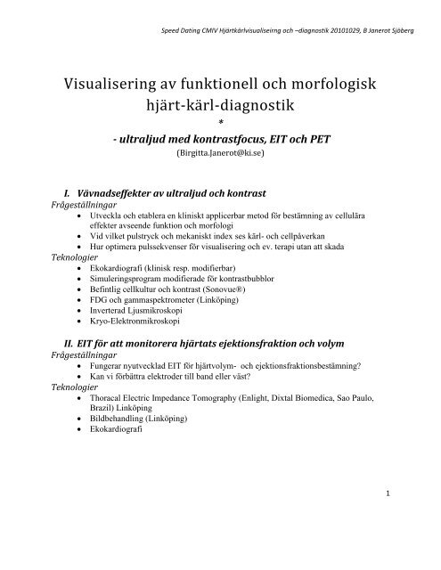
Speed Dating CMIV Hjärt<strong>kärl</strong>visualiseirng <strong>och</strong> –<strong>diagnostik</strong> 20101029, B Janerot Sjöberg<br />
<strong>Visualisering</strong> <strong>av</strong> <strong>funktionell</strong> <strong>och</strong> <strong>morfologisk</strong><br />
<strong>hjärt</strong>-<strong>kärl</strong>-<strong>diagnostik</strong><br />
*<br />
- ultraljud med kontrastfocus, EIT <strong>och</strong> PET<br />
(Birgitta.Janerot@ki.se)<br />
I. Vävnadseffekter <strong>av</strong> ultraljud <strong>och</strong> kontrast<br />
Frågeställningar<br />
� Utveckla <strong>och</strong> etablera en kliniskt applicerbar metod för bestämning <strong>av</strong> cellulära<br />
effekter <strong>av</strong>seende funktion <strong>och</strong> morfologi<br />
� Vid vilket pulstryck <strong>och</strong> mekaniskt index ses <strong>kärl</strong>- <strong>och</strong> cellpåverkan<br />
� Hur optimera pulssekvenser för visualisering <strong>och</strong> ev. terapi utan att skada<br />
Teknologier<br />
� Ekokardiografi (klinisk resp. modifierbar)<br />
� Simuleringsprogram modifierade för kontrastbubblor<br />
� Befintlig cellkultur <strong>och</strong> kontrast (Sonovue®)<br />
� FDG <strong>och</strong> gammaspektrometer (Linköping)<br />
� Inverterad Ljusmikroskopi<br />
� Kryo-Elektronmikroskopi<br />
II. EIT för att monitorera <strong>hjärt</strong>ats ejektionsfraktion <strong>och</strong> volym<br />
Frågeställningar<br />
� Fungerar nyutvecklad EIT för <strong>hjärt</strong>volym- <strong>och</strong> ejektionsfraktionsbestämning?<br />
� Kan vi förbättra elektroder till band eller väst?<br />
Teknologier<br />
� Thoracal Electric Impedance Tomography (Enlight, Dixtal Biomedica, Sao Paulo,<br />
Brazil) Linköping<br />
� Bildbehandling (Linköping)<br />
� Ekokardiografi<br />
1
Speed Dating CMIV Hjärt<strong>kärl</strong>visualiseirng <strong>och</strong> –<strong>diagnostik</strong> 20101029, B Janerot Sjöberg<br />
III. Hitta metabolt aktiva instabila plaque med hjälp <strong>av</strong> PET<br />
Frågeställning<br />
� ”Spotty” <strong>hjärt</strong>upptag på icke-kardiell FDG-PET - tecken till instabil<br />
krans<strong>kärl</strong>ssjukdom ?<br />
� Halsupptag carotisplaque?<br />
Om inte<br />
� kan vi detektera detta på bättre sätt ?<br />
Teknologier<br />
� PET-CT <strong>och</strong> FDG (Linköping)<br />
o Retrospektivt vid icke kardiell FDG-PET (Linköping)<br />
o Kardiell PET/ stilla <strong>kärl</strong>-PET (carotis?)<br />
Forskarmedarbetare sökes lokalt!<br />
Här är vi som arbetar tillsammans idag:<br />
KI /Karolinska US<br />
� Birgitta Janerot S (Prof medicinsk tekonologi, Öl klinisk fysiologi <strong>och</strong><br />
nuklearmedicin; Med bild, funktion <strong>och</strong> teknologi, CLINTEC KI, Alfred Nobels Allé<br />
10 3 tr, Flemingsberg; birgitta.janerot@ki.se, 070 5093397)<br />
� Stig Ollmar (impedans)<br />
� Reidar Winter (ekokardiografi)<br />
� Ss Marcus Ressner (postdoc ultraljudskontrast & sjukhusfysik)<br />
STH<br />
� Hans Hebert m forskargrupp (elektronmikroskopi)<br />
� Dmitry Grishenkov (utv. ultraljudskontrast)<br />
� Lars-Åke Brodin m forskargrupp (<strong>funktionell</strong>a bilder)<br />
CMIV<br />
� Vetenskapligt råd<br />
� Jan Engvall (ultraljud, MR, CT)<br />
� Hans Knutsson m forskargrupp (bildbeh.)<br />
LiU/LiO (Linköping):<br />
� Per Ask m forskargrupp (fysiologisk mätteknik)<br />
� Folke Sjöberg m forskargrupp (microcirk, anestesi, brännskada)<br />
� Laila Hübbert (kardiologi)<br />
� Henrik Ahn m forskargrupp (thoraxkirurgi)<br />
LU:<br />
� Tomas Jansson (ultraljudsfysik)<br />
Med flera<br />
2
<strong>Visualisering</strong> <strong>av</strong> <strong>funktionell</strong> <strong>och</strong><br />
<strong>morfologisk</strong> <strong>hjärt</strong>-<strong>kärl</strong> <strong>hjärt</strong> <strong>kärl</strong>-<br />
<strong>diagnostik</strong><br />
*<br />
- ultraljud med kontrastfocus<br />
kontrastfocus, kontrastfocus<br />
kontrastfocus, , EIT <strong>och</strong> PET<br />
Birgitta Janerot Sjöberg,<br />
Professor Medicinsk<br />
Medicinsk Teknologi Teknologi +<br />
+ Öl<br />
Öl Klinisk fysiologi fysiologi <strong>och</strong> <strong>och</strong> Nuklearmedicin<br />
Nuklearmedicin<br />
Medicinsk bild bild, , funktion<br />
funktion <strong>och</strong> <strong>och</strong> teknologi teknologi, , CLINTEC, CLINTEC, KI<br />
KI<br />
Alfred Nobels Nobels Allé<br />
Allé 10 10 3 3 tr tr, , Flemingsberg<br />
Flemingsberg<br />
Speed Dating CTMH 20101029<br />
Hjärt<strong>kärl</strong>visualisering <strong>och</strong> -<strong>diagnostik</strong><br />
EIT för för att att monitorera<br />
monitorera <strong>hjärt</strong>ats<br />
<strong>hjärt</strong>ats<br />
ejektionsfraktion <strong>och</strong> <strong>och</strong> <strong>och</strong> volym<br />
volym<br />
Frågeställning<br />
Teknologier<br />
�� Fungerar nyutvecklad EIT för ��<br />
<strong>hjärt</strong>volym <strong>hjärt</strong>volym- <strong>och</strong><br />
ejektionsfraktionsbestämning<br />
ejektionsfraktionsbestämning?<br />
Thoracal Electric<br />
Impedance Tomography<br />
(Enlight Enlight, , Dixtal Biomedica,<br />
�� Kan vi förbättra elektroder till<br />
band eller väst?<br />
Sao Paulo Paulo, Brazil)<br />
�� Bildbehandling<br />
�� Ekokardiografi<br />
Forskarmedarbetare<br />
�� KI /Karolinska US<br />
– Birgitta Janerot S<br />
– Stig Ollmar (impedans)<br />
– Reidar Winter ( (ekokardiografi<br />
ekokardiografi)<br />
– Ss Marcus Ressner (postdoc postdoc<br />
ultraljudskontrast & sjukhusfysik)<br />
�� STH<br />
– H Hans Hebert H b t m f forskargrupp k<br />
(elektronmikroskopi)<br />
– Dmitry Grishenkov (utv.<br />
ultraljudskontrast)<br />
– Lars Lars-Åke Åke Brodin m<br />
forskargrupp (<strong>funktionell</strong>a bilder)<br />
�� CMIV :<br />
– Vetenskapligt råd<br />
– Jan Engvall<br />
– Hans Knutsson m<br />
Jan Engvall (ultraljud, MR, CT)<br />
forskargrupp (bildbeh bildbeh.) .)<br />
�� Övr. LiU/LiO LiU/LiO: :<br />
– Per Ask m forskargrupp<br />
(fysiologisk mätteknik)<br />
– Folke Sjöberg m forskargrupp<br />
(microcirk microcirk, , anestesi, brännskada)<br />
– Laila Hübbert (kardiologi) kardiologi)<br />
– Henrik Ahn m forskargrupp<br />
(thoraxkirurgi)<br />
�� LU:<br />
– Tomas Jansson (ultraljudsfysik)<br />
Sökes samarbetspartners !<br />
3<br />
5<br />
Vävnadseffekter <strong>av</strong> ultraljud<br />
<strong>och</strong> kontrast<br />
Frågeställningar<br />
�� Utveckla <strong>och</strong> etablera en<br />
kliniskt applicerbar metod<br />
för bestämning <strong>av</strong> cellulära<br />
effekter <strong>av</strong>seende funktion<br />
<strong>och</strong> morfologi morfologi g<br />
�� Vid vilket pulstryck <strong>och</strong><br />
mekaniskt index ses <strong>kärl</strong>-<br />
<strong>och</strong> cellpåverkan<br />
�� Hur optimera pulssekvenser<br />
för visualisering <strong>och</strong> ev.<br />
terapi utan att skada<br />
Teknologier<br />
�� Ekokardiograf ( (klinisk klinisk resp.<br />
modifierbar)<br />
�� Simuleringsprogram<br />
modifierade difi d fö för<br />
kontrastbubblor<br />
�� Befintlig cellkultur <strong>och</strong> kontrast<br />
(Sonovue Sonovue®) ®)<br />
�� FDG <strong>och</strong> gammaspektrometer<br />
�� Inv - Ljusmikroskopi<br />
�� Kryo Kryo-Elektronmikroskopi<br />
Elektronmikroskopi<br />
Hitta metabolt aktiva instabila<br />
plaque med hjälp <strong>av</strong> PET<br />
Frågeställning<br />
�� ”Spotty Spotty” ” <strong>hjärt</strong>upptag på<br />
icke icke-kardiell kardiell FDG-PET FDG PET -<br />
tecken till till instabil<br />
instabil<br />
krans<strong>kärl</strong>ssjukdom ?<br />
�� Halsupptag carotisplaque?<br />
carotisplaque<br />
Om inte<br />
�� kan vi detektera detta på<br />
bättre sätt ?<br />
Teknologier<br />
�� PET <strong>och</strong> FDG<br />
– Retrospektivt vid icke<br />
kardiell FDG FDG-PET FDG FDG-PET PET<br />
– Kardiell PET/ stilla <strong>kärl</strong>- <strong>kärl</strong><br />
PET (carotis carotis?) ?)<br />
2<br />
4<br />
•1
Automated Analysis and Classification of the Physiological<br />
Condition of the Carotid Artery in 2D Ultrasound Image Sequences<br />
Hamed Hamid Muhammed<br />
School of Technology and Health (STH), Royal Institute of Technology (KTH),<br />
Alfred Nobels Alle 10, SE-141 52 Huddinge, Sweden<br />
e-mail: hamed@sth.kth.se<br />
Tel. +46-8-790 48 55<br />
The objective of research is to develop automated analysis methods for the classification of<br />
the physiological condition of the carotid artery in 2D ultrasound image sequences. The<br />
significance of the new methods is that they are intuitive, automatic, reproducible, and<br />
significantly reduces the reliance upon subjective measures.<br />
Developed methods:<br />
Unsupervised segmentation of vessel walls using both spatial and temporal information.<br />
Automatic speckle tracking to follow the motion of the vessel walls.<br />
Extraction and computation of useful parameters to be used for the pattern recognition and<br />
analysis process.<br />
Both radial and longitudinal motion is considered.<br />
Characteristic radial distension curves are measured in the inner surface of the vessel wall.<br />
Spatio-temporal two-dimensional maps describing the progression of w<strong>av</strong>y patterns along<br />
vessel walls are generated.<br />
Fourier analysis is utilized to obtain easy-to-understand-and-use diagnostic features.
Automated Analysis and Classification<br />
of the Physiological Condition of the<br />
Carotid Artery in 2D Ultrasound Image<br />
Sequences<br />
Hamed Hamid Muhammed<br />
hamed@sth.kth.se<br />
Tel. +46-8-790 48 55<br />
Segmentation result<br />
Hamed Hamid Muhammed hamed@sth.kth.se Tel. +46-8-790 48 55<br />
Carotid artery ultrasound image<br />
Hamed Hamid Muhammed hamed@sth.kth.se Tel. +46-8-790 48 55<br />
Identification of best ROI<br />
Hamed Hamid Muhammed hamed@sth.kth.se Tel. +46-8-790 48 55
Radial distension curves<br />
Hamed Hamid Muhammed hamed@sth.kth.se Tel. +46-8-790 48 55<br />
Young case<br />
Elderly case<br />
Spatio-temporal map of a healthy case<br />
Hamed Hamid Muhammed hamed@sth.kth.se Tel. +46-8-790 48 55<br />
Fourier analysis<br />
Hamed Hamid Muhammed hamed@sth.kth.se Tel. +46-8-790 48 55<br />
Spatio-temporal map of a pathological case<br />
Hamed Hamid Muhammed hamed@sth.kth.se Tel. +46-8-790 48 55
Spatio-spectral maps<br />
Hamed Hamid Muhammed hamed@sth.kth.se Tel. +46-8-790 48 55<br />
Fourier analysis<br />
Hamed Hamid Muhammed hamed@sth.kth.se Tel. +46-8-790 48 55<br />
Fourier analysis<br />
Hamed Hamid Muhammed hamed@sth.kth.se Tel. +46-8-790 48 55
CTMH Speed Dating, Oct 29th, 2010<br />
Finite Element Modeling of the Human Heart<br />
In our project we apply numerical methods to simulate the blood flow in the heart. Based on the model we<br />
apply changes on the geometry to gain a better understanding of the effects on the fluid. Our goal is that the<br />
model might answer clinical hypothesis and we can study diseases and its treatment based on computational<br />
simulations. An important part of the study is to verify the model against medical data.<br />
1 Short description of the current model<br />
The current model consists of the left ventricle<br />
of the heart (LV). The geometry is based on ultrasound<br />
measurements of the position of the inner<br />
wall of the LV at different time points during<br />
the cardiac cycle. We build a three dimensional<br />
mesh of tethrahedrons at the initial time<br />
and use a mesh smoothing algorithm to deform<br />
the mesh so that it fits the dynamic surface geometry.<br />
Finally, an adaptive ALE space-time finite<br />
element solver based on continuous piecewise<br />
linear elements in space and time together with<br />
streamline diffusion stabilization is used to simulate<br />
the blood flow by solving the incompressible<br />
N<strong>av</strong>ier-Stokes equations. Pressure boundary<br />
conditions are prescribed to model inflow from<br />
the mitral valve and outflow through the aortic<br />
valve.<br />
2 Joint Activities<br />
Figure 1: Velocity in the left ventricle<br />
Finite Element Modeling of the Human Heart is a<br />
project promoted by the Computational Technology<br />
Labratory (CTL) at KTH. CTL was created in 2008<br />
with the aim to unify fundamental research on mathematics and computation with applications of high interest<br />
in science, industry and biomedicine, motivated and inspired by interaction with industry and society. The core<br />
of our research is computational mathematical modeling (simulation) with differential equations and adaptive<br />
finite element methods, with implementation of the computational technology in the open source project FEniCS.<br />
Our project started in collaboration with a group working at Ume˚a University (Mats Larsson et al.) which<br />
provided us with the geometry of the heart. We are also in contact with Tino Ebbers who is working with<br />
medical imaging at LiU.<br />
Another collaboration is our joint activity in the KTH-founded SimVisInt project where we h<strong>av</strong>e begun to build<br />
a platform with research groups in haptic and visualization. In this way interactive simulations of the heart are<br />
gained which give feedback on auditory, haptic as well as visual information.<br />
To secure, develop and make our model applicable the discussions, dialogue, feedbacks and inputs from physicians<br />
are of high importance. We are in contact with medical researchers and clinical doctors from the Ume˚a<br />
University and Karolinska Institutet.
Jonas Forsslund, 2010-10-25<br />
KTH School of Computer Science and<br />
Communication, Department of Human-<br />
Computer Interaction<br />
Contact Information<br />
The HCI department currently consist of over 40 members, of which 16 is PhD students. The<br />
head of department is professor Jan Gulliksen, gulliksen@kth.se. The group has formed<br />
several teams and specialized labs of which three a mentioned here (figure 1). The most related<br />
persons to the medical, visualization and perceptualization areas are:<br />
Eva-Lotta Sallnäs Pysander, PhD<br />
Lead of CSC Haptic Lab, evalotta@csc.kth.se, http://bit.ly/cschapticlab<br />
Kristina Groth, PhD<br />
Lead of Interaction Design team, project leader Funki-IS, kicki@csc.kth.se<br />
Gust<strong>av</strong> Taxén, PhD<br />
Lead of Visualization and interaction technology team, gust<strong>av</strong>t@csc.kth.se<br />
Jonas Forsslund, MSc<br />
PhD student perceptualization, member of all three above, part of the Interactive Virtual<br />
Biomedicine (IVB) project together with Alex Olwal, Evalotta Sallnäs Pysander and collaborators<br />
from other departments (Johan Hoffman, Jeanette Spüler et al) jofo02@kth.se<br />
Alex Olwal, PhD<br />
Member of Visualization team and IVB project alx@kth.se<br />
Figure 1. The author is working in the Intersection of Interaction design team, Visualization &
interaction technology team and haptic lab, designing haptic enabled visualization applications<br />
for specific tasks.
jofo02@kth.se<br />
Perceptualization<br />
Jonas Forsslund, MSc, jofo02@kth.se<br />
PhD Student Human-Computer Interaction<br />
Examples of applications<br />
jofo02@kth.se<br />
jofo02@kth.se<br />
Research area<br />
• Perceptualization is an emerging research field<br />
extending visualization to include more senses such as<br />
hearing and touch.<br />
• Haptic feedback ”the use of touch in combination with<br />
motor beh<strong>av</strong>iours to identify objects” objects (Apelle, 1991)<br />
• Collaboration: common ground & awereness<br />
Interactive Virtual Biomedicine<br />
Current status:<br />
• Feel the heart beat.<br />
• Try different fequencies.<br />
Future:<br />
• Support communication<br />
and collaboration<br />
collaboration.<br />
• More data to perceptualize.<br />
Requests:<br />
• What would you dream<br />
to perceive?<br />
• What complex<br />
data can we add?<br />
• How could team work<br />
concerning medical data<br />
be improved?<br />
2010-10-28<br />
1
Visualizing gene expression in clinical medicine<br />
Anders Gabrielsen, MD, DMSc, Dept. of Cardiology and Center for Molecular medicine, CMM L8:03<br />
Background:<br />
During the past years we h<strong>av</strong>e explored the global gene expression (using gene array technology)<br />
patterns of atherosclerosis and the vulnerable carotid atherosclerotic plaque; i.e. the plaque with the<br />
highest risk of developing a thrombosis. We h<strong>av</strong>e identified target genes which identifies “high risk”<br />
patients.<br />
In a similar way we h<strong>av</strong>e identified the important inflammatory molecules and responses to ischemia in<br />
the heart.<br />
Now, we want to translate this into clinical information.<br />
Our main goal is to develop clinical imaging tool(s) to visualize gene expression of target genes in vivo<br />
based on the target genes already identified.<br />
We are working with all state-of-the art technologies of molecular biology, and h<strong>av</strong>e access to all<br />
modern imaging tools. We would prefer to develop a MR-based platform.<br />
Contacts:<br />
Anders Gabrielsen, MD, DMSc,<br />
Dept. of Cardiology and Center for Molecular medicine,<br />
CMM L8:03, 17176 Karolinska Hospital, Stockholm<br />
Tel. 0709 733 886<br />
e-mail: anders.gabrielsen@ki.se<br />
Gabrielle Paulsson Berne, PhD, Ass. Prof.<br />
CMM L8:03, 17176 Karolinska Hospital, Stockholm<br />
e-mail: Gabrielle.berne@ki.se<br />
Ulf Hedin, MD, Prof.<br />
Dept. of Vascular surgery<br />
e-mail: Ulf.Hedin@ki.se
Molecular pathophysiology of<br />
cardiovascular disease.<br />
Anders Gabrielsen, MD, DMSc.<br />
Department of Cardiology and<br />
Center for Molecular Medicine<br />
CMM L8:03,<br />
Karolinska Hospital<br />
17176 Stockholm<br />
BiKE<br />
BiKE (Biobank of Karolinska<br />
Endarterectomies)<br />
To map, identify and understand the key transcript<br />
Registration of Clinical Data patterns involved in atherosclerosis we h<strong>av</strong>e developed<br />
Informed<br />
an in house soft-wear, KI GeneConnect, to<br />
consent<br />
computerize the handling of gene-array data from each<br />
patient to the clinical data base.<br />
Carotid Plaque Blood<br />
Clinical Data Array Data<br />
Gene Array+Morphology+Serum Chemistry+DNA<br />
Clinical parameters are registered in a separate clinical<br />
database; symptoms, morphology of plaque (duplex), serum<br />
analysis (eg inflammatory markers as CRP, fibrinogen,<br />
cholesterols), risk factors (eg smoking, hypertonic, diabetes),<br />
ongoing medical treatment, and earlier/ongoing disease.<br />
Clinical Database<br />
222 Patients –<br />
110 Arrays<br />
Women<br />
32.3%<br />
Men<br />
67.7%<br />
Symptoms<br />
Antal pat.<br />
60<br />
50<br />
40<br />
30<br />
20<br />
10<br />
0<br />
TIA<br />
AF<br />
TIA/AF<br />
Minor Stroke<br />
Asymptomatiska<br />
Okänt<br />
Other Diseases:<br />
Diabetes: 22%<br />
Hypertension: 75%<br />
Medications:<br />
Statins: 69%<br />
Time: Symptom-Surgery<br />
80<br />
70<br />
60<br />
50<br />
Antal pat.<br />
40<br />
30<br />
20<br />
10<br />
0<br />
Pågående Mindre än 1 Mellan 1 <strong>och</strong> Mer än 3 Okänt<br />
symptom månad 3 månader månader<br />
KI GeneConnect<br />
-link clinical and<br />
array data<br />
Translating the transcriptome in<br />
athero-thrombotic athero thrombotic and ischemic heart<br />
disease:<br />
Stroke and myocardial infarction<br />
Cardiovascular Research, Center for Molecular Medicine,<br />
Vascular surgery and Cardiology Departments<br />
Karolinska Institute and Karolinska University Hospital<br />
Present Imaging of vulnerable<br />
lesions<br />
• Detection of<br />
macrophage<br />
infiltration/inflammati<br />
on in lesion<br />
• Ultrasound<br />
• PET-CT (18FDG)<br />
2010-10-28<br />
18 FDG<br />
1
Vision<br />
We want to visualize:<br />
Gene expression (we h<strong>av</strong>e targets)<br />
Inflammation (we h<strong>av</strong>e targets)<br />
Intracellular oxygen status (we know tracers)<br />
Metabolism (we need key targets)<br />
In Vivo<br />
2010-10-28<br />
2
WIDE INTENSITY RANGE SENSOR<br />
FOR MEDICAL IMAGING<br />
Invention<br />
The present invention relates to medical imaging systems for photon<br />
sensing and for measuring photon fluxes in a wide intensity range,<br />
thereby the combinations of detection modalities in one single unit.<br />
The sensor concept utilizes semiconductor technology, and more<br />
specifically integrated arrays of <strong>av</strong>alanche photodiodes (APD), com‐<br />
monly denoted silicon photomultipliers (SiPM), which operate in dual‐<br />
mode: Current integrating mode is used to measure photon flux in the<br />
high intensity range, and Photon counting (Geiger) mode is used to<br />
count individual photons at low to moderate values of intensity.<br />
Application areas<br />
Photon sensing is an important component in many medical and tech‐<br />
nical applications. In medical imaging a primary range of applications<br />
involve coupling the sensor to scintillators sensitive to X‐rays and<br />
gamma rays. Due to the excellent energy/time resolution and wide<br />
intensity range the primary application areas are:<br />
1. Combined systems for CT and PET using a single detector array.<br />
2. CT scanners for both conventional current sensitive readout<br />
mode as well as photon counting mode (low‐dose) where the<br />
individual X‐ray photons are detected and characterized with‐<br />
out influence of electronic noise on the image quality.<br />
3. Combined therapeutic and diagnostic imaging for medical ra‐<br />
diation therapy.<br />
Advantages<br />
Detectors based on the new sensor concept can combine functions<br />
that today are performed in separate detector systems. The result is<br />
higher performance at potentially lower cost. More specifically;<br />
• Higher quality of fused images for PET/CT.<br />
• Higher image quality at lower patient dose for combined pho‐<br />
ton counting and standard charge integrating CT.<br />
• Reduced production cost for PET/CT systems.<br />
• Compact systems requiring less hospital space.<br />
• No need for time and resource demanding calibrations of two<br />
separate detectors. Simplified calibration procedures.<br />
• Insensitivity to strong magnetic fields can thereby be used to‐<br />
gether with magnetic resonance imaging (MRI) systems.<br />
• Higher patient throughput.<br />
20010-10-15<br />
Application areas<br />
Medical imaging<br />
Dosimetry<br />
Radiography<br />
Status IPR<br />
Patents (SWE,EP) granted<br />
Offer<br />
Licence contract<br />
Patent purchase<br />
Development cooperation<br />
Contact<br />
CIREA AB<br />
www.cirea.se<br />
Prof. Bo Cederwall<br />
Department of Physics<br />
The Royal Institute of<br />
Technology (KTH)<br />
S‐106 91 Stockholm,<br />
Sweden<br />
Fax: +46 (0)8 55378216<br />
Tel: +46 (0)8 55378203<br />
cederwall@nuclear.kth.se
WIDE INTENSITY RANGE SENSOR<br />
FOR MEDICAL IMAGING<br />
20010-10-15<br />
History of development<br />
The detector concept has been developed by Professor Bo Cederwall at the Department of Physics,<br />
Royal Institute of Technology (KTH), Stockholm, Sweden. Prof. Cederwall is specialized in radiation<br />
detection utilizing scintillators and semiconductor technology. Today a lab scale prototype detector<br />
exists with clear proof of concept. A compact prototype detector module is under development.<br />
Offer<br />
The offer is a licence contract, purchase of the patent and/or development cooperation.<br />
IPR<br />
Priority date April 2, 2007<br />
Priority number, designated state(s), status SE20070000825 SE Granted<br />
Further applications , designated state(s), status SE531025(C2) SE Granted<br />
Further applications , designated state(s), status EP2132541(A1) EP Granted<br />
Business rationale<br />
Multimodality imaging in particular combined computed tomography (CT) and positron emission<br />
tomography (PET) has brought a new perspective into the fields of clinical and preclinical imaging. It<br />
is now widely recognized that the combination of anatomical structures revealed from CT and the<br />
functional information from PET provides an enhanced diagnostic tool and also offers an important<br />
research potential. There is also a strongly increasing interest in photon‐counting CT systems due to<br />
the higher image contrast and lower radiation doses possible using detectors capable of detecting<br />
and characterizing individual X‐ray photons. Ideally, a CT detector system should be capable of both<br />
readout modes, although technical solutions h<strong>av</strong>e been lacking up to now.<br />
The worldwide market size for CT is around 7 billion USD with roughly 40.000 installed systems. The<br />
largest growth areas are cardiology, which drives the development of yet faster systems to enable<br />
high quality beating heart imaging, and low‐dose CT, driven by a strong increase of children analyses<br />
and an increased awareness that the radiation dose acquired by patients during a standard CT ex‐<br />
amination involves a non‐negligible risk of inducing cancer. The present invention targets the latter<br />
area and due to its multimodality, low‐dose photon counting CT operation can be included in a high‐<br />
speed CT system. The market size for combined PET/CT is about 1 billion USD and has with wide<br />
margins passed the market of stand‐alone PET systems. The application area oncology drives the<br />
development of PET/CT systems with 95 % of all executed analyses and an annual growth rate of 30<br />
%. The present invention would enable a PET/CT scanner with one common detector system and<br />
thereby higher imaging performance, but also cost s<strong>av</strong>ings; both as an initial investment (lower<br />
manufacturing cost) and as lower operational costs, primarily due to simplified calibration proce‐<br />
dures and a higher patient throughput.
WIDE INTENSITY RANGE SENSOR<br />
FOR MEDICAL IMAGING<br />
APPENDIX: Technical rationale<br />
20010-10-15<br />
The photomultiplier tubes used together with scintillator crystals to detect X‐rays and gamma rays in PET and<br />
CT scanners, as well as single photon emission computed tomography (SPECT) scanners are in current state‐of‐<br />
the‐art systems being replaced by photo detectors based on semiconductor technology; conventional photodi‐<br />
odes or <strong>av</strong>alanche photodiodes (APDs). A major rationale behind this ongoing transition to silicon‐based de‐<br />
vices is that they can operate in a strong magnetic field and, thus, provide the technology for combined<br />
CT/SPECT/PET systems and magnetic resonance imaging (MRI) systems.<br />
Today, different detector and readout systems are used For CT and PET due to the difference in photon ener‐<br />
gies and radiation intensities between these two imaging techniques. For PET, the energy‐ and timing informa‐<br />
tion of every photon is measured (photon counting mode). In standard CT applications where the flux of X‐ray<br />
photons is much higher (on the order of 10 9 photons/mm 2 s), current integration is used with a time constant<br />
adjusted to provide a readout frequency that matches the rotational motion of the detector gantry. The re‐<br />
quirement of two separate detector systems implies more complex, expensive and cumbersome radiation<br />
detection devices than would be the case if both imaging modalities could be supported by a common detector<br />
system. In addition, a higher image quality would be achievable due to higher image fusion accuracy.<br />
Standard CT detectors use scintillators coupled to photodiodes providing an electrical current signal propor‐<br />
tional to the intensity of illumination. A drawback of these detectors is their inability to provide energy discri‐<br />
minatory data or otherwise count the number and/or measure the energy of photons actually received by a<br />
given detector element or pixel. On the other hand, current mode is the only practical readout mode at the<br />
very high X‐ray flux rates used for conventional CT examinations. Development of photon counting CT systems<br />
is currently in focus and is driven by the the higher image contrast and lower radiation doses possible using<br />
detectors capable of photon counting and energy discrimination. Ideally, a CT detector system should be capa‐<br />
ble of both readout modes, although technical solutions h<strong>av</strong>e been lacking up to now.<br />
The silicon photomultiplier (SiPM) photo sensor technology is a highly promising new development for medical<br />
imaging systems like CT, PET and SPECT. SiPM‐based scintillation detectors, which exhibit excellent timing and<br />
energy resolution, are also being developed for other applications of radiation detection. Moreover, SiPMs<br />
require a minimum of front‐end electronics and can be mass produced at low cost.<br />
The present detector concept is tailored for SiPMs coupled to scintillator crystals, which can be operated in<br />
either current integrating or photon counting (Geiger) mode. In applications with high radiation fluxes, such as<br />
high‐speed X‐ray CT imaging or portal imaging systems, utilization of APDs or SiPMs operated in single‐photon<br />
counting mode is not possible or inefficient due to saturation effects caused by dead time and pulse pile‐up.<br />
The maximum count rate per detector element in state‐of‐the‐art single‐photon counting systems is well below<br />
the mean count rate per unit area required in standard CT imaging. In photon counting mode, such as for PET,<br />
APDs can practically be used for rates up to about 10 MHz, also limited by the decay time of the scintillator.<br />
Therefore, common photodiodes that photovoltaically generate a current that is essentially proportional to the<br />
energy flux of the measured radiation are normally used for such high‐dose rate applications.<br />
Consequently, for applications requiring a wide dynamic range of photon fluxes, such as a combined CT/PET<br />
system or a CT‐system operating in both photon counting and current integrating mode, two separate detector<br />
systems h<strong>av</strong>e previously been required; one detector system comprising, e.g., common photodiodes for ena‐<br />
bling high‐rate current readout needed for fast CT scanning, and one high gain detector system consisting of,<br />
for example, APDs for enabling high‐resolution single‐photon readout needed for photon counting CT and for<br />
PET and SPECT scanning.<br />
The present invention, via its dual mode operation, is designed to overcome this limitation and thereby enables<br />
a technological leap to multiple‐modality medical imaging with a single type of radiation detector head. This
WIDE INTENSITY RANGE SENSOR<br />
FOR MEDICAL IMAGING<br />
20010-10-15<br />
will improve performance and cost efficiency of such systems.<br />
Another key application is for imaging in connection with radiation‐based cancer therapy where it is important<br />
to couple as closely as possible the diagnostic imaging of the patient with the portal imaging that is performed<br />
on‐line to verify the dose delivery. This invention will enable the design of a single detector system that can<br />
perform diagnostic CT/PET as well as verifying the dose delivery during a cancer therapy session. This will im‐<br />
prove the accuracy, quality and efficiency of the dose delivery and lead to higher protection of healthy tissues<br />
by reducing uncertainties in patient positioning and by providing the possibility of on‐line corrections to the<br />
therapeutic beam.<br />
Technical Details 1)<br />
The present detector concept consists of integrated APD microstructure arrays, often called silicon photomulti‐<br />
pliers (SiPMs) or multi‐pixel photon counters (MPPCs), coupled to scintillator crystals. It can be operated in<br />
both current integrating and photon counting mode.<br />
A SiPM consists of hundreds or thousands of microcell Geiger mode APDs per mm 2 and typical sensor areas<br />
range from a below 1 mm 2 up to tens of mm 2 . The area of each sensor (i.e. pixel size in an imaging system) can<br />
easily be tailored for the application by the manufacturer. The SiPM's main working regime is in the high‐gain<br />
Geiger mode where the bias voltage, VB, is set above the breakdown voltage Vbr, where a gain of around 10 5 ‐<br />
10 6 can be reached. A single photon is sufficient to excite a cell and the output charge is constant, independent<br />
on the number of incident photons on the cell. The microcells are connected in parallel and thus the output<br />
charge is proportional to the number of excited cells, i.e. the number of incoming scintillation photons. This<br />
property introduces an effectively linear response (Eq. 1) with a relatively wide dynamic range if the <strong>av</strong>erage<br />
number of incident photons is small relative to the number of cells.<br />
An integrated quenching resistor limits the <strong>av</strong>alanche and allows each cell that has fired to reset after a time of<br />
the order of tens of nanoseconds. During this time the pixels are effectively shut down and are insensitive to<br />
incoming photons. This property would normally make the sensor unsuitable for operation in standard CT ap‐<br />
plications where very high X‐ray fluxes are commonly used. In high‐speed CT examinations the X‐ray photon<br />
flux can easily exceed 10 9 photons/mm 2 , which is orders of magnitude higher than the flux that can be sup‐<br />
ported by any photon counting detector system. However, if the bias voltage is lowered below the breakdown<br />
point, the pixels act as normal APDs, i.e. the device has much lower gain but with no pixel dead time, as a<br />
trade‐off. By reducing the bias voltage to below the breakdown voltage the dynamic intensity range of the<br />
sensor is extended by many orders of magnitude, restoring the linear response of the sensor for current mode<br />
operation (e.g. to be proportional to the X‐ray photon energy flux) and allowing for high‐rate applications such<br />
as standard CT.<br />
Typical characteristics of current state‐of‐the art SiPMs include;<br />
• Photon Detection Efficiency of up to ~80% (and expected to improve as the SiPM technology matures)<br />
• Sensitive to individual photons (embedded gain ~ 10 6 ‐10 7 )<br />
• Requires low reverse voltage ~ 20‐80 V and operates at room temperature
WIDE INTENSITY RANGE SENSOR<br />
FOR MEDICAL IMAGING<br />
20010-10-15<br />
A first‐stage detector prototype module has been developed as a proof‐of‐concept for combined PET/CT or a<br />
CT system that combines photon counting readout for low dose applications with standard current mode rea‐<br />
dout. An energy resolution of 12.3% at 662 keV with a 137 Cs source was measured using a LSO scintillator. The<br />
32 keV K X‐ray line from 137 Ba was resolved above the noise level in this measurement, see Fig. 2. This indicates<br />
a good potential for photon counting of low‐energy X‐rays which is essential in some CT applications. Timing<br />
resolution is essential, in particular for time‐of‐flight (TOF) PET and it has been measured with<br />
a 22 Na source together with a BaF2 detector as a reference, resulting in a value of 1.0 ns (FWHM) for the timing<br />
resolution at Eγ = 511 keV. Both time and energy resolution is expected to improve with optimized optical<br />
coupling between the scintillator and SiPM. The inherent time resolution of the SiPM sensor is below 100 ps.<br />
The current generated in the SiPM is measured in parallel with the pulse mode operation by means of a current<br />
sensitive amplifier (see Fig. 3). The SiPM hence acts as a current generator, the current being proportional to<br />
the incoming photon energy flux. This can be done simultaneously with the pulse mode operation. However,<br />
for certain applications it is desirable to optimize the readout in current integrating mode. Typically this occurs<br />
for very high signal rates. One example is if the device is used for a (system of) scintillation detector(s) for X‐<br />
rays or gamma rays. If the number of incident secondary photons per unit area of the device becomes compa‐<br />
rable to the pixel density, significant nonlinearities in the sensor response when it operates in photon counting<br />
mode will be present. Such saturation effects will affect both the current integrating mode and photon count‐<br />
ing operation. For event rates which are large with respect to the single‐pixel recovery time or to the decay<br />
time of the scintillator saturation effects will occur due to pileup. At such event rates, typically above 1 MHz<br />
per mm 2 , the photon counting mode operation is no longer efficient. In such cases the bias voltage can be re‐<br />
duced to below the breakdown voltage, restoring the linear response of the sensor for current integrating<br />
mode operation.<br />
Fig. 1 One of the simplest sensor readout<br />
schemes is presented. Several other varia‐<br />
tions exist. For instance, it may be desir‐<br />
able to add a protective RC‐circuit be‐<br />
tween the voltage supply and the SiPM. In<br />
pulse mode, the signals generated by the<br />
SiPM can be used directly (the SiPM has an<br />
intrinsic gain of the order of 10 6 – 10 7 ) or<br />
optionally be amplified before being sent<br />
on to the pulse processing electronics (not<br />
shown in the figure). If amplifiers are used,<br />
only relatively simple, low‐gain (~x10)<br />
devices are needed. The mean current<br />
generated by the SiPM is read out simulta‐<br />
neously. For event rates which are large<br />
with respect to the detector time response<br />
characteristics, like the single‐pixel recov‐<br />
ery time or to the decay time of the scintil‐<br />
lator, saturation effects will occur due to<br />
pileup. At high flux rates the sensor can<br />
therefore be switched seamlessly to pure<br />
current mode operation by lowering the<br />
bias voltage below the breakdown value.<br />
The dynamic intensity range is thereby<br />
increased by many orders of magnitude.
WIDE INTENSITY RANGE DETECTOR<br />
FOR MEDICAL IMAGING<br />
2010-08-04<br />
Fig 2. Energy spectrum of gamma‐ and X‐<br />
rays from a radioactive source ( 137 Cs) taken<br />
with the first‐stage prototype module.<br />
Fig 3. Correlated current and pulse measure‐<br />
ment using a laser diode taken with the first‐<br />
stage prototype module.<br />
1) For further details see: Andreas Persson, Anton Khaplanov , Bo Cederwall and Christian Bohm,<br />
“A prototype detector module for combined PET/CT or combined photon counting/standard CT based<br />
on SiPM technology”, to be published in IEEE transactions on Nuclear Science.
Optical sensor with a wide dynamic intensity range<br />
“wide-range photodiode”<br />
Invention based on SiPM (MPPC, MPAD) technology<br />
Bo Cederwall<br />
The Royal Institute of Technology (KTH) / CIREA AB<br />
Wide range sensor for combined medical imaging systems<br />
Solutions to these challenges: Wide range sensor based on SiPM* technology<br />
- Can be used in a variety of applications that demand detection of individual photons<br />
or photon fluxes, here as an integral part of scintillation detectors for X-rays and<br />
gamma rays.<br />
- The invention enables the sensor to work with good properties (linearity, sensitivity<br />
etc) in a very wide intensity range.<br />
- Functions that are performed by separate systems with today’s technology can be<br />
integrated into one system.<br />
-Higher performance and precision<br />
- Simple calibration procedure in pulse mode (sensor is essentially ”digital”)<br />
- Cost benefits, more compact imaging systems<br />
Wide range sensor for combined medical imaging systems<br />
The need for radiation sensors in medical imaging with a wide dynamic intensity range<br />
Integrated PET/CT detectors<br />
Our sensor concept enables integrated detector systems with common sensors for anatomical and<br />
functional imaging.<br />
Today: separate detector systems handle imaging<br />
Integrated detector system with common sensors<br />
Combined photon counting mode and standard mode CT<br />
CIREA AB Wide range sensor for combined medical imaging systems<br />
* Also called MPPC, MPAD<br />
� higher imaging accuracy by<br />
perfect alignment of images<br />
� lower cost, higher patient throughput<br />
� reduced space requirements<br />
� shorter examinations, reduces patient stigma<br />
Would enable lower patient doses and higher image contrast by registration and characterization of<br />
individual photons without noise, when this is possible or necessary<br />
Specialized photon counting CT imaging systems are under strong development but will h<strong>av</strong>e special<br />
applications like for pediatrics or 3D mammography. Such systems saturate under normal conditions.<br />
A system that can perform both normal and spectral photon counting CT gives a large clinical advantage.<br />
CIREA AB Wide range sensor for combined medical imaging systems<br />
CIREA AB<br />
Basis of the Invention:<br />
Simultaneous/switchable readout of SiPM sensors in current and pulse mode<br />
Sensor works in pulse mode (spectral photon counting) as a normal photomultiplier<br />
or APD + amplifier .<br />
Typical application scintillation detector for PET/SPECT<br />
or photon counting CT. (Simultaneous current readout possible)<br />
For high-intensity applications the sensor is tuned to optimise current readout mode<br />
(as typically for standard photodiodes in e.g. normal CT applications)<br />
� ”infinite” intensity range<br />
Dynamic switching between pulse mode and current mode possible<br />
CIREA AB
Main target applications<br />
1. Integrated current mode / spectral photon counting CT<br />
(”simple” conversion of existing CT systems � shortest path to clinical use and<br />
the lowest investment threshold)<br />
1. Integrated PET/CT<br />
2. Combined therapeutic and diagnostic imaging<br />
Wide range sensor for combined medical imaging systems<br />
PET/CT – future today<br />
Original picture from Siemens Medical<br />
Wide range sensor for combined medical imaging systems<br />
PET/CT<br />
Hybrid of two basic imaging modalities<br />
CT scanner (high-resolution anatomical images)<br />
PET scanner (high-quality functional images)<br />
Computer and software fuses images<br />
No patient movement between registrations<br />
“Look into the body and see what happens there (on a molecular level)”<br />
CIREA AB Wide range sensor for combined medical imaging systems<br />
PET/CT – possible implementation in CT mode<br />
CIREA AB Wide range sensor for combined medical imaging systems<br />
CIREA AB<br />
Original picture from Siemens Medical<br />
CIREA AB
Integrated standard / spectral photon counting CT system<br />
Counts and characterizes individual X-ray photons<br />
Can measure the energy of every detected X-ray photon and achieve<br />
better image contrast sensitivity for a given dose<br />
Needed for pediatric examinations and 3D mammography where dose is a<br />
key factor<br />
System includes high count rate capability of standard CT for conventional<br />
examinations<br />
Dynamic switching between modes<br />
Wide range sensor for combined medical imaging systems<br />
IP – CIREA AB<br />
“System and method for photon detection”, B. Cederwall /CIREA AB<br />
Priority date<br />
April�2,�2007<br />
Priority number, designated state(s), status SE20070000825 SE Granted<br />
Further applications , designated state(s), status SE531025 (C2) SE Granted<br />
Further applications , designated state(s), status EP2132541 (A1) EP Granted<br />
Wide range sensor for combined medical imaging systems<br />
Integrated Portal – diagnostic (CT/SPECT/PET) imaging for cancer therapy<br />
Today’s diagnostic imaging is typically performed separate from radiation therapy<br />
sessions<br />
This reduces accuray in cancer treatment due to patient movement, anatomical<br />
changes with time (dose delivery usually via multiple sessions over several<br />
weeks)<br />
(Large effort on IMRT and planning, less on this problem)<br />
Therapeutic imaging yields poor resolution and contrast and requires high-rate<br />
radiation hard sensors.<br />
Large potential gain with integrated therapeutic and diagnostic detector system<br />
Solution: wide-dynamic-range radiation sensor<br />
� Identical patient – detector alignment<br />
� High-quality fused anatomical and therapeutic images<br />
� Lower dose to healthy tissue, higher killing power (lower recurrence rate)<br />
CIREA AB Wide range sensor for combined medical imaging systems<br />
Where we are<br />
Proof of concept established<br />
IP protection in place<br />
Basic prototype demonstrator near completion<br />
CIREA AB Wide range sensor for combined medical imaging systems<br />
CIREA AB<br />
CIREA AB
Vision<br />
The new sensor concept is applied in the three key application areas:<br />
Combined current mode / spectral photon counting CT.<br />
Here only detector heads and software need be replaced in current CT systems –<br />
the shortest path to clinical use of the technology.<br />
Integrated PET/CT<br />
Combined therapeutic/diagnostic imaging system for cancer therapy, largely<br />
based on PET/CT.<br />
Wide range sensor for combined medical imaging systems<br />
Background information<br />
Wide range sensor for combined medical imaging systems<br />
Commercial implementation routes<br />
We develop detector modules for key applications, in collaboration with systems<br />
manufacturer.<br />
We license/ sell IP to systems / component manufacturer, in combination with the<br />
above.<br />
We license/ sell IP to systems / component manufacturer<br />
CIREA AB Wide range sensor for combined medical imaging systems<br />
Silicon Photomultiplier (SiPM) – basic characteristics<br />
CIREA AB Wide range sensor for combined medical imaging systems<br />
CIREA AB<br />
Detection efficiency, currently ~25%-40%<br />
Sensitive to single photons (high intrinsic gain ~10 5 -10 7 )<br />
Can measure pulsed/continuous photon fluxes due to many active<br />
elements (~ 100 – 20000 pixels)<br />
- emulates function of classic PM tubes<br />
Operational characteristics:<br />
– Needs low bias voltage ~20-80 V,<br />
– Works at room temperature<br />
– Insensitive to magnetic fields (compatible with MR)<br />
– Requires a minimum of electronics<br />
– Dark rate ~ 100 – 500 kHz (single pixels firing)<br />
Miniatyrized and possible to pack in matrices.<br />
Low cost (estimated < $10/pce for mass production)<br />
Recently in production at Pulsar, Hamamatsu Photonics, SensL and others<br />
CIREA AB
Resistor<br />
Rn=400 k�<br />
-20M �<br />
Al<br />
Depletion<br />
Region<br />
2 �m<br />
SiPM today-reminder:<br />
42�m<br />
20�m<br />
V bias<br />
pixel<br />
Substrate<br />
h�<br />
R 50�<br />
� Pixel size ~20-100�m<br />
Wide range sensor for combined medical imaging systems<br />
crystal<br />
photodetector<br />
PMT<br />
APD<br />
SiPM<br />
� Working point: V Bias = V breakdown + �V ~ 20-80 V<br />
�V ~ 10-20% above breakdown voltage<br />
�Each pixel beh<strong>av</strong>es as a Geiger counter with<br />
Q pixel = �V C pixel with C pixel~50fF �<br />
Q pixel~150fC=10 6 e<br />
Wide range sensor for combined medical imaging systems<br />
Electrical inter-pixel cross-talk<br />
minimized by:<br />
- decoupling quenching resistor for each pixel<br />
- boundaries between pixels to decouple them<br />
� reduction of sensitive area<br />
and geometrical (packing) efficiency<br />
Very fast Geiger discharge development < 1 ns<br />
Pixel recovery time = (Cpixel Rpixel) > ~ 20 ns<br />
Dynamic range ~ number of pixels � saturation<br />
SiPM: photon counting detector with “quasi-linear” properties<br />
preamp<br />
N photons �PDE<br />
� � �<br />
�<br />
N pixels<br />
N � �<br />
�<br />
firedpixels<br />
N pixels 1 e<br />
�<br />
�<br />
�<br />
�<br />
shaper<br />
CR-RC<br />
In Geiger mode the amplitude dynamic range is ~ 10 3<br />
This is ”perfect” for PET/SPECT (pulse mode)<br />
A<br />
D<br />
C<br />
•<br />
•<br />
•<br />
SiPM - structure<br />
Two steps in the development of SiPMs<br />
� STEP 1: Single Photon Avalanche Diode : Geiger-mode APD (SPAD) � “single pixel photon counter”<br />
� STEP 2: Integrated Matrix of SPADs with common (parallel) readout:<br />
Silicon Photomultiplier (SiPM)<br />
Depletion<br />
1-2�m<br />
substrate<br />
V b<br />
R 50�<br />
CIREA AB Wide range sensor for combined medical imaging systems<br />
h�<br />
50�<br />
Multipixel Geiger mode<br />
photodiode with common<br />
readout.<br />
Area typically �1-10 mm 2<br />
Microcell structure on<br />
common silicon substrate<br />
“Simple” CMOS technology.<br />
CIREA AB Wide range sensor for combined medical imaging systems<br />
CIREA AB<br />
Spectral response with 241Am and 22Na @ 60, 511 and 1274 keV<br />
Saturation effects due to finite number of pixels<br />
CIREA AB
Simultaneous pulse and current mode measurement @ 60 keV, 241 Am source<br />
Wide range sensor for combined medical imaging systems<br />
High-rate saturation effects ct’d<br />
Wide range sensor for combined medical imaging systems<br />
High-rate saturation effects<br />
CIREA AB Wide range sensor for combined medical imaging systems<br />
Current measurement with pulsed LED<br />
The detector “saturates”* when operated in Geiger mode whereas<br />
the linear response is retained in the sub-Geiger regime.<br />
CIREA AB Wide range sensor for combined medical imaging systems<br />
CIREA AB<br />
* Saturation occurs here first due to the current load, at higher frequencies due to the SiPM recovery time<br />
CIREA AB
Prototype electronics<br />
• Multipurpose prototype electronics board*<br />
• Controlled via labview interface.<br />
• High bandwith current integrating amplifier for high-speed CT. Will handle rapid<br />
current fluctuations present during a CT scan. Includes 4 photon counting<br />
discriminators for ”quick and dirty” spectral PC CT. Read out via NI 6212 USB 8ch<br />
16-bit FADC, NI6602 4ch counter<br />
• Charge sensitive preamp (full spectral PC CT, PET)<br />
• Compact mobile prototype unit ”demonstrator”<br />
* 8-layer board developed in collaboration with ÅF, to be implemented as ASICs for specific applications<br />
Wide range sensor for combined medical imaging systems<br />
SiPM “response function”, low-level light<br />
Q 2phe<br />
Q1phe Q3phe<br />
P<br />
Q 4phe<br />
Q 5phe<br />
Q 6phe<br />
Wide range sensor for combined medical imaging systems<br />
Prototypelektronik i samarbete med ÅF system design<br />
CIREA AB Wide range sensor for combined medical imaging systems<br />
Excellent timing resoluton (e.g. for PET)<br />
Two SiPM+LYSO crystals in coincidence<br />
for two gamma’s of 511 KeV (CFD)<br />
1400<br />
1200<br />
1000<br />
800<br />
600<br />
400<br />
200<br />
0<br />
380 400 420<br />
TDC channel (1 ch=0.1 ns)<br />
B. ’ Dolgoshein,LIGHT06<br />
FWHM=0.78 ns<br />
Laser (CFD)<br />
Drake, Chen et al., ANL<br />
CIREA AB Wide range sensor for combined medical imaging systems<br />
FWHM 28ps<br />
CIREA AB<br />
CIREA AB
SiPM insensitive to magnetic fields – MR compatible<br />
SiPM tested in up to 4T<br />
Wide range sensor for combined medical imaging systems<br />
CIREA AB
Image fusion – hybid imaging (Kenneth Caidahl et al)<br />
Hybrid imaging means the combination of different imaging techniques to obtain an image with<br />
special information which can be difficult for the eye to combine correctly when studying one<br />
technique at a time. This can be achieved in various ways.<br />
-Combined equipment with fixed positions, internal plane corrections<br />
-Spatial sensors for positions<br />
-Image fusion by pattern recognition<br />
In the recently started EU project 3Micron (coordinating centre KTH, professor Lars-Åke Brodin), we<br />
aim at developing a multimodal contrast bubble. This means it should be possible to use with<br />
ultrasound, magnetic resonance imaging (MR), single photon emission tomography (SPECT) and<br />
positron emission tomography (PET). It will be possible to use such contrast for one technique at a<br />
time, but the possibility to combine techniques to illustrate the same process, ideally with<br />
simultaneous otherwise subsequent imaging, is a major advantage.<br />
The technique to combine SPECT or PET with computed tomography (CT) is now well established.<br />
Combination of PET and MRI is emerging. The combination of ultrasound with other techniques<br />
constitutes the greatest challenge since positioning is free and it means external sensors need to be<br />
used. Also image fusion by means of pattern recognition is possible, and even with external sensors<br />
this is required. At least one commercial ultrasound company is working in this direction.<br />
Image fusion is also interesting for experimental laboratory work, in vivo, ex vivo or for cell cultures.<br />
The recording by different techniques can be compared. Yet another field is the comparison over<br />
time regarding development or reduction of pathologic processes like cancer or atherosclerosis. Even<br />
in very close time relationship for evaluation with and without contrast, comparison of the same<br />
tissue or structure is essential.<br />
The described problem is thus essential both for experimental work and in the clinical setting, and<br />
there are a number of interesting applications.<br />
References<br />
Kaufmann PA. Cardiac hybrid imaging: state-of-the-art. Ann Nucl Med 2009;23:325-331<br />
Even-Sapir E, Keidar Z, Bar-Shalom R. Hybrid imaging (SPECT/CT and PET/CT) – improving the<br />
diagnostic accuracy of functional / metabolic and anatomic imaging. Semin Nucl Med 2009;39:264-<br />
275<br />
Matsuo S, Nakajima K, Akhter N, Wakabayashi H, Taki KJ, Okuda K, Kinuya S. Clinical usefulness of<br />
novel MDCT / SPECT fusion image. Ann Nucl Med 2009; 23:579-86.
Kenneth.Caidahl@ki.se; prof<br />
Torkel.Brismar@gmail.com; assoc prof<br />
Björn.Gustafsson@ki.se; post doc<br />
Anton.Razuvaev@ki.se; post doc<br />
Åsa.Barrefelt@ki.se; PhD student<br />
And more<br />
KI, 3MiCRON<br />
Clinical Physiology & Radiology<br />
Collab<br />
Groups of prof Lars-Åke Brodin, KTH<br />
Ulf Hedin, Vasc Surg, CMM and more<br />
Image<br />
fusion<br />
Hybrid<br />
technique<br />
Courtesy Dianna Bone<br />
Dept Clin Physiol Karolinska<br />
Total<br />
Small
Decision making tools in the diagnosis of pulmonary embolism<br />
by means of SPECT/CT imaging<br />
The scintigraphic diagnosis of pulmonary embolism (PE) is based on visual assessment of perfusion<br />
scintigraphy combined with ventilations scintigraphy according to PIOPED criteria.<br />
The revised PIOPED criteria include the assessment of severity of perfusion defect in a different lung<br />
segment. The size of defect categorized as small= 25 but < 75% and large=>75%<br />
of lung segment evaluated on planar images. Even widely used for many years, planar perfusionventilation<br />
(V/Q) scintigraphy has well recognized limitations.<br />
Introduction of Single Photon Emission Tomography (SPECT) overcomes many of these limitations<br />
through its ability to generate 3-dimentional imaging data. V/Q SPECT has been shown to h<strong>av</strong>e a<br />
greater sensitivity and specificity than planar imaging and a lower non-diagnostic rate.<br />
The use of SPECT can facilitate advances in V/Q imaging, including the generation of parametric V:Q<br />
ratio images, coregistration with Computed Tomography(CT) and more accurate quantification of<br />
regional lung function.<br />
New generation of hybrid cameras such as SPECT/CT and PET/CT is now <strong>av</strong>ailable in several<br />
modern nuclear medicine centres in Europe and Sweden.<br />
Given the tomographic nature of both SPECT and CT data, fused images can be obtained by using<br />
data acquired in a single scanning session on such hybrid camera with a greater registration accuracy.<br />
Such approach may potentially combine the high sensitivity of SPECT with the high specificity of CT.<br />
Moreover, hybrid SPECT/CT scanners allow each lobe of the lung to be accurately identified on CT<br />
and mapped back onto the functional data on SPECT, thereby facilitating anatomically accurate<br />
assessment of individual lobar contribution to lung perfusion.<br />
Although the main clinical indication for V/Q scintigraphy is in the evaluation of PE, there are other<br />
indications in with SPECT/CT should h<strong>av</strong>e an important role. For patients with lung cancer before<br />
lung reduction surgery, it is useful to know the relative contribution to total function of the lobe(S) to<br />
be excised. Planar scanning has been used for this purpose. However, because of the known<br />
anatomical overlap of the lobes of the lung this approach is inherently inaccurate.<br />
By now, there is no commercially <strong>av</strong>ailable soft wear to perform such mapping or quantification.<br />
Some references:<br />
Baley DL, Roach PJ, Bailey EA et al. Development of a cost-effective modular SPECT/CT scanner.<br />
Eur J Nucl Med Mol Imaging 2007; 34:1415-26<br />
Ketai L, Hartshorne M: Potential uses of SPECT and CT coincidence fusion images of the chest. Clin<br />
Nucl med 2001; 26: 433-41.<br />
Jamadar DA, Kazerooni EA, Martinez FJ et al. Semi-quantitative ventilation/perfusion scintigraphy<br />
and single-photon emission tomography for evaluation of lung volume reduction surgery candidates:<br />
description and prediction of clinical outcome. Eur J Nucl med 1999; 26: 734-42.<br />
Freeman LM, Blaufox MD. Pulmonary Embolism. Seminars in Nuclear Medicine 2008, 38 N6.<br />
Rimma.Axelsson@ki.se
Decision making tools<br />
in the diagnosis of<br />
pulmonary embolism<br />
by means of SPECT/CT imaging<br />
MD., Ph.D, Associate Professor<br />
Rimma Axelsson<br />
Radiology Department,Karolinska Universitetssjukhus,Huddinge<br />
CLINTEK, KI<br />
29 Oktober 2010<br />
Imaging Pulmonary Embolism (PE)<br />
• Perfusion scintigraphy ( P or Q) since 1964<br />
evaluating vascular tree and possible<br />
occlusions.<br />
• In order to improve methods specificity<br />
combination with ventilation ( evaluationg<br />
bronchial tree) scintigraphy (V) since 1970<br />
• Findings of perfusion defect with preserved<br />
ventilation in the corresponding area is called<br />
for VQ mismatch and considered as a sign for<br />
PE<br />
• Planar imaging, 8 projections
X-ray exam VQ scan in patient with PE<br />
Criteria for VQ scan interpretation:<br />
modified PIOPED<br />
• Normal - no perfusion defects<br />
• Very- low probability- Small VQ matches, with a normal chest Xray.<br />
Non-segmental perfusion defects, including cardiomegaly, enlarged hila<br />
or aorta<br />
• Low probability –Large or moderate focal VQ matches involving no<br />
more than 50% of the combined lung fields, with no corresponding<br />
radiographic abnormalities. Small VQ mismatches, with a normal chest xray<br />
• Intermediate probability – difficult to categorize or not described<br />
as very low, low or high, including cases with a chest X-ray opacity, pleural<br />
fluid or collapse. Single moderate VQ match or mismatch without<br />
corresponding radiographic abnormality<br />
• High probability – 2 or more moderate/large mismatched perfusion<br />
defects. Prior cardiopulmonary disease probably requires more<br />
abnormalities(4 or more). Triple match in one lung with one or more<br />
mismatch in the other<br />
Definition of perfusion defects<br />
• Small 25 <strong>och</strong> 75% of a segment
MDCT-central PE<br />
Pulmonary<br />
segments<br />
• So, the accurate<br />
interpretation of VQ<br />
scans is a chllenging<br />
cognitive task involving<br />
integration of perfusion<br />
and ventilation signal<br />
with the chest X-ray.<br />
Further developments in diagnosis<br />
of PE<br />
• Multi Detector CT (MDCT) for detection of PE since late<br />
1990-ties<br />
• Single Photon Emission Tomography<br />
(SPECT) beginning of 2000-s – 3-dimentional<br />
imaging data. Comparable or grater sensitivity<br />
than MDCT for PE,with no contrast-related<br />
complications such as allergy and nephropathy,<br />
low radiation dose to the breast,no need for<br />
sustained breath hold or injection timing to<br />
acquisition.<br />
• SPECT/CT-<br />
Further developments in diagnosis<br />
of PE<br />
• Multi Detector CT (MDCT) for detection of PE since late<br />
1990-ties<br />
• Single Photon Emission Tomography<br />
(SPECT) beginning of 2000-s – 3-dimentional<br />
imaging data. Comparable or grater sensitivity<br />
than MDCT for PE,with no contrast-related<br />
complications such as allergy and nephropathy,<br />
low radiation dose to the breast,no need for<br />
sustained breath hold or injection timing to<br />
acquisition.<br />
• SPECT/CT-
SPECT perfusion transversal reconstruction SPECT perfusion coronal reconstraction<br />
SPECT: perfusion + ventilation, coronal<br />
reconstractions<br />
Patient with PE?
Quantification before surgical removment of a lob<br />
in patient with lung cancer<br />
Is it possible to make a soft<br />
ware for quantification of<br />
perfusion defects?<br />
Rimma.Axelsson@ki.se
POLYMER-SHELLED CONTRAST AGENTS FOR ULTRASOUND,<br />
SPECT AND MRI.<br />
Dr. Dmitry Grishenkov<br />
Ultrasound-based imaging technique is probably the most used approach for rapid<br />
investigation and monitoring of anatomical and physiological conditions of internal<br />
organs and tissues.<br />
The ultrasound imaging technique can be greatly improved by the use of contrast agents<br />
to enhance the signal from the area of interest relative to the background. Typically<br />
ultrasound contrast agent (UCA) is a suspension of the microbubbles consist of a gas<br />
core encapsulated within the solid shell. Generally these devices are injected systemically<br />
and function to enhance the ultrasound echo. The ideal UCA should be manufactured<br />
from the biocompatible material; be easily injected into the cardiovascular system either<br />
using bolus or continuous infusion; be stable during the ultrasound examination; do not<br />
cause any obstruction of the flow; remain within the blood pool or h<strong>av</strong>e well-defined<br />
specific tissue distribution; after destruction the residues should be safely processed and<br />
removed from the body. Neither material of the shell no encapsulated gas should be<br />
harmful or toxic for the organism. From the technical point of view UCA should modify<br />
the acoustic properties of the tissue, for instance by increasing ultrasound backscattered<br />
efficiency, or introducing harmonic component to the echo, or combination of both.<br />
The overall objective of the project is to test novel polymer shelled UCAs as a possible<br />
new generation of multifunctional contrast agents not only for Ultrasound technique but<br />
also for MRI and SPECT.<br />
In recent years, the UCA has moved from being just visualization tool to a new<br />
multifunctional and complex device for drug or gene therapy and targeted imaging. The<br />
new medical and technological approach of contrast enhanced ultrasound concerns<br />
“theranostics”, i.e. combination of therapy and diagnostics. Therapeutic systems are not<br />
any longer stand alone approach against a disease. On the contrary, they tent to integrate<br />
in to diagnostic techniques such as ultrasound, MRI and CT. With the help of these<br />
techniques in combination with novel UCAs local and specific drug delivery become<br />
possible. Within the frame of the project the surface of the polymer microballoon has<br />
been decorated with the pharmacological agents and the protocol for c<strong>av</strong>itation mediated<br />
release of the drug is established. The cutting-edge result of these integrated functions is<br />
the administration of a much lower drug dosage, <strong>av</strong>oiding the side effects of<br />
pharmaceutical overload.<br />
The latest trend in contrast enhanced sonography is so called molecular imaging, which is<br />
non-invasive imaging technique to visualize and monitor in real time very fine changes<br />
on the molecular level. Nowadays, the key modalities for molecular imaging are MRI,<br />
SPECT and PET. However, increasing interest is shown in introduction of specific<br />
targeted contrast ultrasound technique to the molecular imaging due to its unique<br />
features: high temporal resolution, low-cost and wide <strong>av</strong>ailability.<br />
In conclusion, the proposed polymer-shelled gas-core microbubbles can be considered as<br />
a prospective next generation of contrast agents, which allows not only multimodality<br />
image enhancement relevant to diagnostics but also localized and specific drug delivery<br />
for non-invasive therapy.
Polymer-Shelled<br />
Contrast Agent<br />
for<br />
Ultrasound, SPECT and MRI<br />
Drug delivery<br />
Echocardiography<br />
Dr. Dmitry Grishenkov<br />
Medical Engineering<br />
School of Technology and Health KTH<br />
Flemingsberg, Sweden<br />
Contrast ultrasound<br />
Molecular imaging<br />
Oncology<br />
Thrombosis<br />
1<br />
3<br />
Microbubble<br />
Type<br />
Ideal Contrast Agents<br />
• Manufactured from biocompatible material<br />
• Injected<br />
• Stable<br />
• Do not cause obstruction<br />
• Remain within the blood pool<br />
• Processed by the body<br />
• Modify acoustic or magnetic properties of RoI<br />
Ultrasound Contrast Agents<br />
Average Diameter<br />
(μm)<br />
1. Local or specific<br />
drug delivery<br />
2. Magnetic material<br />
3. Radioisotope<br />
Average Shell<br />
Thickness (μm)<br />
MB_pH5_RT 4.1 ± 0.7 0.7 ± 0.1<br />
MB_pH5_Cool 2.7 ± 0.6 0.5 ± 0.1<br />
MB_pH2_Cool 2.6 ± 0.5 0.5 ± 0.1<br />
SonoVue ® 2.5<br />
(polydisperse 1-10 μm)<br />
≈2.5×10⁻³ 2<br />
4
3MICRON (Collaborative EU Project)<br />
Aims:<br />
1. Enhancement of the imaging techniques<br />
2. Combined imaging between US, SPECT<br />
and MRI will be supported by shellmodified<br />
microbubbles.<br />
5
Simulation of arterial flows<br />
with<br />
Clinical relevance<br />
Laszlo Fuchs, Mechanics, KTH<br />
Background:<br />
Cardio-vascular diseases cause about 50% of mortalities in Western countries. Most of cardiovascular<br />
events are related to atherosclerosis and associated problems. Arterial lesions are focal in<br />
character (near branches and bends in larger arteries) and therefore cannot be explained only in<br />
terms chemical-immunological processes if the blood composition is assumed to be homogenous.<br />
Our research addresses some basic questions related to pulsatile blood flows in larger arteries and in<br />
particular in branches.<br />
Goals:<br />
The projects are aimed both at basic understanding of the flow itself, the interaction between the<br />
flow and the blood and the effects of the flow on the arterial walls. Additionally, we apply the basic<br />
understanding to problems of clinical interest.<br />
Understanding of the fluid mechanical contribution to atherosclerosis has been a topic of research<br />
over long time. It is believed that the flow itself only cannot explain the very slow and multifacetted<br />
process of atherosclerosis. Our hypothesis is the flow affects not only the stresses on the<br />
walls of the arteries but also the composition of the blood (cells and solvents) locally, whereby the<br />
process becomes localized. Local blood composition changes also the rheology of the blood which<br />
results in modification of the flow itself. This impact of this non-linear interaction is unknown.<br />
Potential clinical applications:<br />
The forces acting on the walls of the arteries and the physiological response to the temporarily and<br />
spatially varying stresses may also lead to aneurysm. The flow is also affected by the particular type<br />
of arterial reconstruction. Understanding these aspects can lead to patient specific arterial (and<br />
bypass) surgery. Similarly, blood flow in extracorporeal systems (e.g. heart-lung machines,<br />
hemodialysis) can be improved and/or reducing hazard by utilizing the gained knowledge.<br />
Methods and models:<br />
We use computational and experimental tools for studying the flow, mixing and vessel-flow<br />
interaction in relevant geometries. We are developing models for blood rheology based on the local<br />
red-blood-cell and macro-molecule concentration. We also develop models for describing the local<br />
distribution of solvents with different diffusivities (depending on molecule size). The forces acting<br />
on the walls and the resulting deformation of the vessel is also included in the modelling research.<br />
The experimental work includes measuring the flow (time-resolved local velocity vector), and local<br />
concentrations of substances with different molecular diffusivities. All measurements are done<br />
using non-intrusive methods. We measure the velocity using Laser Doppler Velocimetry (LDV) or<br />
Particle Image Velocimetry (PIV). These methods are more accurate than ultra-sound based<br />
technique which is more suitable for optically opaque cases. Concentration of solvents is measured<br />
simultaneously with the velocity using Laser Induced Fluorescence (LIF) utilizing multiple lasers.
Contact information:<br />
Prof. Laszlo Fuchs<br />
Department of Mechanics<br />
KTH<br />
Tel: 08-790 7155<br />
Mobile: 070-5728466<br />
e-mail: lf@mech.kth.se<br />
Recent publications:<br />
1. P. Evegren, J. Revstedt and L. Fuchs -Wall Shear Stress Variations in a 90-degree Bifurcation<br />
in 3D Pulsating Flows, Medical Engineering & Physics, 32, pp.189–202, 2010.<br />
2. P. Evegren, J. Revstedt and L. Fuchs - On the secondary flow through bifurcating pipes. Phys.<br />
Fluids, 22, 103601, doi:10.1063/1.3484266, 2010<br />
3. P. Evegren, J. Revstedt and L. Fuchs - Pulsating flow and mass transfer in an asymmetric<br />
system of bifurcations. Submitted to Computers and Fluids.
v/v peak<br />
Simulation of arterial flows<br />
with with<br />
Clinical Clinical relevance relevance<br />
Laszlo Fuchs<br />
101029<br />
Dept. of Mechanics<br />
KTH<br />
Arterial flow in a bifurcation<br />
Generalized geometries<br />
• Circular cross-section<br />
• Rigid smooth walls<br />
1<br />
0.9<br />
0.8<br />
0.7<br />
0.6<br />
0.5<br />
0.4<br />
0.3<br />
0.2<br />
0.1<br />
Inlet<br />
0<br />
0 0.1 0.2 0.3 0.4 0.5 0.6 0.7 0.8 0.9 1<br />
t/T<br />
Outlets<br />
Boundary conditions<br />
• Pulsating inlet velocity<br />
• No slip wall condition<br />
• Pressure outlet (0 gauge)<br />
1. Goals<br />
Outline<br />
a. Basic understanding of<br />
i. Atherosclerosis<br />
ii. Aneurysm � rupture<br />
iii. Dynamics of blood component distribution<br />
iv. Blood rheology<br />
b. Clinical aspects<br />
i. Stent insertion<br />
ii. Patient specific reconstruction<br />
iii. Dialysis<br />
iv. Hemodilution<br />
2. Examples<br />
i. Flow dynamics<br />
ii. Time- & space-variation of Wall Shear Stress<br />
iii. Solvent distribution<br />
Selected Results<br />
� �<br />
6<br />
. 75<br />
Re �1450<br />
Black dots show<br />
areas of negative<br />
axial WSS.
Experiment<br />
Selected Results<br />
� �11.<br />
75<br />
Re �1450<br />
Black dots show<br />
areas of negative<br />
axial WSS.<br />
Selected Results<br />
Scalar distribution<br />
• Distribution affected<br />
by inlet BC<br />
Only one region<br />
Sc=6800<br />
Selected Results<br />
Axial flow contours<br />
� �<br />
separation<br />
6<br />
. 75<br />
Re �1450<br />
Bold line -<br />
zero contour
Integration of Finite Element Simulations in the clinical work flow of Abdominal Aortic<br />
Aneurysm patients<br />
T.Christian Gasser, PhD, KTH Solid Mechanics<br />
Jesper Swedenborg, MD, PhD, Department of Molecular Medicine and Surgery at KI<br />
Joy Roy MD, PhD, Department of Molecular Medicine and Surgery at KI<br />
Martin Auer, PhD, VASCOPS GmbH, Austria<br />
Vascular biomechanics – Computer simulations of clinical problems<br />
Interdisciplinary research in the field of biomechanics, with particular emphasize on simulation<br />
techniques to solve clinically relevant problems. Previous and current work includes:<br />
o In-vitro experimental investigation of soft biological tissues.<br />
o Reconstruction of vascular bodies from Computer Tomography Angiography (CT-A) images<br />
for Finite Element (FE) analysis.<br />
o Continuum mechanical modeling of the non-linear elastic, the visco-elastic and the elastoplastic<br />
properties of vascular tissue.<br />
o Computational Fluid Dynamics (CFD) of blood flow through normal and diseased arteries.<br />
o Numerical description of non-linear failure mechanics by means of the discontinuous FE<br />
method and cohesive zone models.<br />
o Modeling growth of Abdominal Aortic Aneurysms<br />
Requested additional know-how<br />
Imaging with emphasize on functional imaging of vascular tissues.<br />
Research project in the field of biomedical engineering<br />
o Young Faculty Grant No. 2006-7568. 'Integrated biomechanically based diagnoses of<br />
Abdominal Aortic Aneurysms' funded by Swedish Research Council, VINNOVA and the<br />
Swedish Foundation for Strategic Research (since 2007)<br />
o Project Grant No. 2008-6837. 'Penetration of soft biological tissues' funded by Swedish<br />
Research Council (since 2008)<br />
o Collaborative Project 2006-47. 'Fighting Aneurysmal Disease (FAD)' funded by European's<br />
Seventh Framework Program (since 2008)<br />
Affiliation and contact information of group members<br />
T.Christian Gasser, PhD<br />
Phone: 0046 8 790 7793 Mobile: 0046 73 4301328<br />
e-mail: tg@hallf.kth.se<br />
Webpage: www.hallf.kth.se/vascumech<br />
Affiliation: Lektor (bitr.) at KTH Solid Mechanics<br />
Jesper Swedenborg, MD, PhD<br />
Phone: 0046 8 15201 3689<br />
e-mail: jesper.swedenborg@ki.se<br />
Webpage: http://www.cmm.ki.se/en/Research/Cardiovascular-and-Metabolic-Diseases/Vascular-<br />
Surgery/
Affiliation: Professor emeritus at Department of Molecular Medicine and Surgery at KI<br />
Joy Roy, MD, PhD<br />
Phone: 0046 8 15201 3689<br />
e-mail: joy.roy@ki.se<br />
Webpage: http://www.cmm.ki.se/en/Research/Cardiovascular-and-Metabolic-Diseases/Vascular-<br />
Surgery/<br />
Affiliation: Vascular surgeon at the Department of Molecular Medicine and Surgery at KI<br />
Martin Auer, PhD<br />
Phone: 0043 (0) 660 7675296<br />
e-mail: martin.auer@vascops.com<br />
Webpage: http://www.vascops.com /<br />
Affiliation: CTO at VASCOPS GmbH, Vienna, Austria
Integration of Finite Element Simulations in<br />
the clinical work flow of Abdominal Aortic<br />
Aneurysm patients<br />
T.Christian Gasser, PhD, Department of Solid Mechanics at KTH<br />
Jesper Swedenborg, MD, PhD, Department of Molecular Medicine and Surgery at KI<br />
Joy Roy, MD, PhD, Department of Molecular Medicine and Surgery at KI<br />
Martin Auer, PhD, VASCOPS GmbH, Austria<br />
Speed Dating Workshop, Oct. 29, Stockholm, Sweden<br />
Model Definition and Development<br />
Intended use of the model predictions<br />
Mechanical Testing<br />
Microscopy<br />
Material Model<br />
Comp. Model<br />
A4clinics<br />
Speed Dating Workshop, Oct. 29, Stockholm, Sweden<br />
Image reconstruction<br />
Patient data<br />
Introduction and Background<br />
Biomechanics as part of the clinical decision making<br />
process<br />
Clinical Problem Comp. Model Model Prediction Treatment<br />
A model represents the real object to some degree of completeness. …<br />
as simple as possible but not simpler!<br />
Speed Dating Workshop, Oct. 29, Stockholm, Sweden<br />
Example– Aneurysm rupture risk assessment<br />
A4clinics (VASCOPS GmbH)<br />
CT-A Data<br />
PPatient i DData<br />
Speed Dating Workshop, Oct. 29, Stockholm, Sweden<br />
Maximum Diameter<br />
Peak Wall Rupture<br />
Risk (PWRR)<br />
2010-10-28<br />
1
Example– Aneurysm rupture risk assessment<br />
Clinical implication of the Peak Wall Rupture Risk (PWRR)<br />
Speed Dating Workshop, Oct. 29, Stockholm, Sweden<br />
http://www.hallf.kth.se/vascumech/<br />
http://www.vascops.com/<br />
Detailed Information<br />
Speed Dating Workshop, Oct. 29, Stockholm, Sweden<br />
Tack!<br />
2010-10-28<br />
2
Anders Björling<br />
St. Jude Medical<br />
175 84 Järfälla<br />
Office: 08 - 474 4578<br />
Cell: 0739 - 737 958<br />
Visualization of the heart’s venous anatomy<br />
A pacemaker is connected to one to three leads implanted into or in contact with the<br />
heart. The purpose of the leads is to sense the heart’s electrical activity and to electrically<br />
stimulate the heart to initiate a contraction.<br />
Implantation of a traditional pacemaker, h<strong>av</strong>ing one or two leads, is a simple procedure.<br />
Implanting leads into the right atrium (RA) and right ventricle (RV) is very fast. It takes<br />
in the order of a few minutes to cannulate the subcl<strong>av</strong>ian vein, slide the leads into the<br />
heart, position them in the right location and make sure that the sensing and pacing<br />
capabilities are sufficient. The complete implantation time is in the order of 45 minutes.<br />
The procedure is performed under local anesthesia and mild sedation. It is conducted in a<br />
catheterization lab and fluoroscopy is used to visualize the leads and implant tools needed<br />
to position the leads.<br />
Biventricular devices, or CRT devices, h<strong>av</strong>e an additional lead accessing the left<br />
ventricle. This lead is implanted transvenously through the coronary sinus and into a<br />
coronary vein on the outside of the left ventricle, preferably in a left lateral vein. This<br />
lead is much more complicated to implant than the ones in the RA or RV; in rare cases<br />
the lead implantation can take up to several hours. Also, in many cases it’s very difficult<br />
to implant the lead so one has to be satisfied with a non-optimal position. As previously<br />
mentioned, the implant procedure is performed in the catheterization lab which means<br />
that the patient and the physician may be subjected to a large amount of X-ray radiation.<br />
In order to visualize the venous anatomy on the fluoroscopy images a venogram is<br />
created. This is done by inflating a balloon in the coronary sinus, injecting contrast and<br />
taking an X-ray image. This is not always easy and several attempts may be needed. The<br />
contrast agent affects the kidneys and puts an extra stress on these. Many of the patients<br />
receiving a CRT device h<strong>av</strong>e kidney failure or reduced kidney function why this extra<br />
stress is very serious.<br />
Also, in about 30% of all patients the therapy does not work. It is not known why it does<br />
not always work, but it is thought that lead position is a very important factor. It is<br />
difficult to know beforehand where it is possible to place the lead in a good position.<br />
Even if a venogram is made and a vein is found in a good position, it is not always<br />
possible to place the lead there. The vein may be too thin for the lead to enter or the way<br />
to it may be very tortuous and difficult to access.<br />
So in summary, being able to answer the following questions positively would be of great<br />
value:<br />
• Is it possible, before the operation begins, to identify those patients in whom it is<br />
not possible to place the lead in a good position due to their difficult venous<br />
anatomy?<br />
• Is it possible, at a very early stage of the operation, to identify those veins which<br />
can not be accessed due to too small size, too tortuous or other?<br />
• Is it possible, preferably before the operation begins, to create a venogram without<br />
using a contrast agent?
3<br />
Visualization of the heart’s<br />
venous anatomy<br />
Anders Björling, St. Jude Medical<br />
Background<br />
� A biventricular pacemaker stimulates both the right and<br />
left ventricle of the heart<br />
� The aim is to synchronize the cardiac contraction, shown<br />
to improve survival in heart failure (HF) patients<br />
� The performance of the therapy relies he<strong>av</strong>ily on the<br />
position of the left lead placed in a coronary vein<br />
� The implantation of leads is done in a catheterization lab<br />
using fluoroscopy (X-ray)<br />
� To visualize the coronary vein anatomy, a contrast agent<br />
is injected into the bloodstream<br />
2<br />
4<br />
How do you visualize<br />
the heart’s venous anatomy<br />
using a<br />
non-invasive or minimally y invasive method, ,<br />
without using a<br />
contrast agent affecting renal function?<br />
Problems and needs<br />
� It is difficult to obtain a high quality cardiac venogram<br />
� It is not always possible to know from the venogram if a lead can be<br />
implanted in a specific vein or not<br />
� The used X-ray contrast agent affect renal function, often already<br />
compromised in HF patients<br />
� Acquiring a high quality venogram and identifying possible lead<br />
locations before the operation and without the use of contrast would<br />
lead to:<br />
� Shorter procedure times<br />
� Less exposure to X-ray<br />
� Higher responder rate as patients in whom a lead can not be<br />
placed in a good position are identified early<br />
� Less effect on patients’ kidneys<br />
1
Pre- and per-operative mapping of substrates for atrial fibrillation<br />
Mats Jensen-Urstad Dept of Cardiology Karolinska Huddinge<br />
Techniques<br />
Contact mapping<br />
After catheterization but before ablation, multielectrode contact-mapping and voltage map of<br />
the left atrium is done. In practice a multipolar electrode catheter is moved in the left atrium<br />
along all walls, and data regarding localization and local electrogram is collected on-line to a<br />
computer for analysis. A 3-dimensional map is created where local electrograms can be studied<br />
in detail and the amplitude can be presented in the 3-D picture to identify and quantify areas<br />
with low voltage indicating fibrosis.<br />
Non-contact mapping<br />
Electrophysiological registration will be done with non-contact mapping that is a technique<br />
where a specially designed multiarray balloon catheter is placed in a heart chamber. Over<br />
3000 local electrograms is simultaneuosly collected with a time resolution of 2 ms which then<br />
is presented in a 3-D model where regional electrical activity, propagation speed can be<br />
analysed beat to beat.<br />
MRI with late enhancement<br />
MRI scanning is done 15 min following contrast injection using a 3D inversion recovery,<br />
repiration n<strong>av</strong>igated, ECG gated, gradient echo pulse sequence.
Pre- and per-operative mapping of substrates for atrial fibrillation<br />
Mats Jensen-Urstad Dept of Cardiology Karolinska Huddinge<br />
mail: mats.jensen-urstad@karolinska.se<br />
tel:08-58580000 psök 7433<br />
mobile: 0706-301006<br />
Forskargrupp<br />
Mats Jensen-Urstad, docent, överläkare<br />
Jonas Schwieler, docent, överläkare<br />
Frieder Braunschweig, docent, överläkare<br />
Per Insulander, PhD, överläkare<br />
Jari Tapanainen, PhD, överläkare<br />
Bita Sadigh, PhD, bitr överläkare<br />
Hamid Bastani, doktorand, bitr överläkare<br />
Nikola Drca, doktorand, bitr överläkare<br />
Kristjan Gudmundsson, doktorand, specialistläkare<br />
Rasmus H<strong>av</strong>möller, PhD, specialistläkare<br />
Samtliga vid elektrofysiologiska sektionen, <strong>hjärt</strong>klinken Karolinska Universitetssjukhuset<br />
mail: förnamn.efternamn@karolinska.se
Pre- and per-operative<br />
mapping of substrates for<br />
atrial fibrillation<br />
Mats Jensen-Urstad<br />
Department of Cardiology<br />
Karolinska Huddinge<br />
• Catheter ablation with radio frequency or<br />
cryo as energy source is used to cure both<br />
paroxysmal and persistent atrial fibrillation<br />
• With currrent indications need for 3000-<br />
4000 procedures/year in Sweden<br />
• Costly ~100000 SKr/procedure<br />
• Lower short- and longterm success rate<br />
than for other ablation procedures<br />
Background<br />
• Atrial fibrillation (AF) is the most common<br />
arrhythmia of clinical significans. In the EU<br />
about 4,5 million people suffers from AF.<br />
AF gives rise to extreme economical costs<br />
with a yearly cost of 3000 €/patient, in<br />
total 13.5 milliards € yearly in the EU.<br />
How to improve?<br />
• Patient selection<br />
• Techniques
Techniques<br />
• Multipolar contact and non-contact<br />
mapping of local ECG. Mapping areas with<br />
low electrical amplitudes<br />
• MRI with late enhancement<br />
Contact and non-contact<br />
mapping
MRI with late enhancement<br />
• MRI<br />
• Gadolinium<br />
• Delayed Enhancement<br />
• Scar? Fibrosis? Inflammation?<br />
Marrouche 2009
Posterior-anterior and anterior-posterior view of enhancemnet (green pattern) vs. normal healthy<br />
tissue (blue) before ablation in patients with lone AF.<br />
Marrouche 2009<br />
Utah I was defined as ≤5% LA wall enhancement, Utah II as >5% and ≤20%,<br />
Utah III as >20% and ≤35%, and Utah IV as >35%.<br />
297 patienter med PAF el pers FF<br />
Marrouche et al 2010<br />
Marrouche 2009
• Can we by preoperative MRI optimize<br />
treatment?<br />
• Can we by intraoperative<br />
electroanatomical mapping optimze the<br />
ablation procedure?<br />
• Do MRI and electro-anatomical mapping<br />
give the same information?
CTMH Speed Dating, Oct 29th, 2010<br />
Finite Element Modeling of the Human Heart<br />
In our project we apply numerical methods to simulate the blood flow in the heart. Based on the model we<br />
apply changes on the geometry to gain a better understanding of the effects on the fluid. Our goal is that the<br />
model might answer clinical hypothesis and we can study diseases and its treatment based on computational<br />
simulations. An important part of the study is to verify the model against medical data.<br />
1 Short description of the current model<br />
The current model consists of the left ventricle<br />
of the heart (LV). The geometry is based on ultrasound<br />
measurements of the position of the inner<br />
wall of the LV at different time points during<br />
the cardiac cycle. We build a three dimensional<br />
mesh of tethrahedrons at the initial time<br />
and use a mesh smoothing algorithm to deform<br />
the mesh so that it fits the dynamic surface geometry.<br />
Finally, an adaptive ALE space-time finite<br />
element solver based on continuous piecewise<br />
linear elements in space and time together with<br />
streamline diffusion stabilization is used to simulate<br />
the blood flow by solving the incompressible<br />
N<strong>av</strong>ier-Stokes equations. Pressure boundary<br />
conditions are prescribed to model inflow from<br />
the mitral valve and outflow through the aortic<br />
valve.<br />
2 Joint Activities<br />
Figure 1: Velocity in the left ventricle<br />
Finite Element Modeling of the Human Heart is a<br />
project promoted by the Computational Technology<br />
Labratory (CTL) at KTH. CTL was created in 2008<br />
with the aim to unify fundamental research on mathematics and computation with applications of high interest<br />
in science, industry and biomedicine, motivated and inspired by interaction with industry and society. The core<br />
of our research is computational mathematical modeling (simulation) with differential equations and adaptive<br />
finite element methods, with implementation of the computational technology in the open source project FEniCS.<br />
Our project started in collaboration with a group working at Ume˚a University (Mats Larsson et al.) which<br />
provided us with the geometry of the heart. We are also in contact with Tino Ebbers who is working with<br />
medical imaging at LiU.<br />
Another collaboration is our joint activity in the KTH-founded SimVisInt project where we h<strong>av</strong>e begun to build<br />
a platform with research groups in haptic and visualization. In this way interactive simulations of the heart are<br />
gained which give feedback on auditory, haptic as well as visual information.<br />
To secure, develop and make our model applicable the discussions, dialogue, feedbacks and inputs from physicians<br />
are of high importance. We are in contact with medical researchers and clinical doctors from the Ume˚a<br />
University and Karolinska Institutet.
Contact Information: Finite Element Modeling of the Human Heart<br />
Project Leader<br />
Johan Hoffman<br />
Associate Professor in Numerical Analysis<br />
School of Computer Science and Communication<br />
Royal Institute of Technology KTH<br />
Contact:<br />
School of Computer Science and Communication<br />
Royal Institute of Technology KTH<br />
SE-10044 Stockholm<br />
Sweden<br />
Email:jhoffman@kth.se<br />
Phone: +46 (0)8 790 7783<br />
Homepage: http://www.csc.kth.se/∼jhoffman/<br />
Project Members<br />
Johan Jansson<br />
Researcher in Numerical Analysis<br />
School of Computer Science and Communication<br />
Royal Institute of Technology KTH<br />
Contact:<br />
CSC<br />
KTH<br />
100 44 Stockholm<br />
SWEDEN<br />
Email:jjan@nada.kth.se<br />
Phone: +46 (0)8 790 6417<br />
Homepage: http://www.csc.kth.se/∼jjan/<br />
Jeannette Spuhler<br />
PhD in Numerical Analysis<br />
School of Computer Science and Communication<br />
Royal Institute of Technology KTH<br />
Contact:<br />
KTH Royal Institute of Technology<br />
Lindstedtsvägen 3, Plan 5<br />
Numerisk Analys (NA)<br />
SE-100 44 Stockholm, Sweden<br />
Email:spuhler@kth.se<br />
Phone: +46-8-790 62 67<br />
Homepage: http://www.csc.kth.se/∼spuhler/
���������������������������<br />
���������������<br />
����������������������������������<br />
��������������������������������������������<br />
������������������������� �� �����<br />
������������<br />
� ��������������������������������������������������������������������<br />
� ��������������������������������������������������������<br />
���������������������������������������������������������������������<br />
�������������������<br />
� �������������������������������������������������������������<br />
��������������������������������������������<br />
�<br />
�<br />
������������<br />
� ���������������������������������������������<br />
������������������������������������<br />
� �������������������������������������������<br />
�������������������������������������������<br />
������������������������<br />
� ����������������������������������������<br />
����������������������������������������������<br />
�����������������������������������������<br />
�����������<br />
� ������������������������������������������������<br />
��������������������������<br />
� ������������������������������������������<br />
���������������������������������������������<br />
�����������������������������������������<br />
�����������<br />
�u��u�� �u���u�� p� f<br />
��u�0<br />
� ����������������������������������������������<br />
����������������������������������������<br />
�����������������������������������<br />
� �������������������������������������<br />
� �����<br />
�<br />
�
Medical UIs, Augmented Reality &<br />
Hybrid Interaction Techniques<br />
Alex Olwal alx@kth.se www.olwal.com<br />
Human-Computer Interaction, KTH<br />
INTRODUCTION<br />
The fundamental idea of Augmented Reality (AR) is to improve<br />
and enhance our perception of the surroundings,<br />
through the use of sensing, computing and display systems.<br />
This makes it possible to augment the physical environment<br />
with virtual computer graphics.<br />
UNOBTRUSIVE AR<br />
The user experience in AR is primarily affected by the display<br />
type, the system’s sensing capabilities, and the means<br />
for interaction. The display and sensing techniques determine<br />
the effectiveness and possible realism, but may at the<br />
same time h<strong>av</strong>e ergonomic and social consequences.<br />
Unobtrusive AR emphasizes walk-up-and-use scenarios<br />
with spontaneous interaction and minimal user preparation.<br />
Unencumbering technology is emphasized, as it<br />
<strong>av</strong>oids setups that rely on user-worn equipment, such as<br />
head-worn displays or motion sensors.<br />
Unobtrusive AR merges the real and virtual, while preserving<br />
a clear and direct view of the real, physical environment,<br />
and <strong>av</strong>oiding visual modifications to it. It presents<br />
perspective-correct imagery without user-worn equipment<br />
or sensors, and supports direct manipulation, while <strong>av</strong>oiding<br />
encumbering technologies.<br />
Figure 1. Interaction and display are distributed and synchronized<br />
across multiple mobile devices and the large interactive surface. This<br />
enables collaborations between local and remote users, enabling<br />
each user to use the device and input controls of their choice.<br />
HYBRID INTERACTION TECHNIQUES<br />
As the capabilities of display systems, mobile devices, ubiquitous<br />
computing and input devices continue to evolve,<br />
there are many advantages of a heterogenous blend of interaction<br />
technologies, as shown in Figure 1. Such hybrid<br />
user interfaces exploit the ability to distribute and combine<br />
the interactive capabilities of different devices, to provide<br />
the best possible user experience. Through tracked mobile<br />
devices, it is, for example, possible to complement interactions<br />
with a large display, by overcoming its limitations in<br />
visual output and touch input as shown in Figure 2.<br />
Numerous input technologies that can be used for remote<br />
and unobtrusive sensing of user’s interactions are also becoming<br />
widely <strong>av</strong>ailable. These are, in particular, wellsuited<br />
for Spatial AR configurations, where augmentations<br />
are created with see-through displays or projectors situated<br />
in the environment. Figure 3 and 4 show the ASTOR system<br />
and a range of incorporated technology for directmanipulation.<br />
Figure 2. A tracked handheld display complements interactions with<br />
a large projection. The handheld provides higher quality and higher<br />
resolution(11X) focus in its viewport, while the larger screen provides<br />
the context. [Olwal and Feiner 2009]<br />
MEDICAL USER INTERFACES<br />
We are currently witnessing a technological revolution with<br />
unprecedented connectivity, mobility, distributed computational<br />
power, ubiquitous sensing, advanced displays, and<br />
interactivity, which is especially interesting for medical<br />
user interfaces. We h<strong>av</strong>e started to explore the use of our<br />
techniques to improve efficiency, safety and quality in various<br />
medical scenarios, including:<br />
• Examinations (pre-op): for interpretation / analysis<br />
• Team meetings /collaboration / planning<br />
• Tele-medicine / mHealth: Remote consulting and teleexpertise<br />
for rural areas / developing countries<br />
• Operation / Surgery: Interaction and visualization for<br />
more efficient use of current medical imaging equipment.<br />
• Post-op & education: Validate and improve procedures<br />
and improve training and experience.<br />
Figure 3. Left) The ASTOR system uses projectors behind a machine<br />
operator to illuminate a holographic optical element, which is optically<br />
combined with the view of the machine, as seen through the safety<br />
glass. Right) The system extracts real-time measurements from the<br />
industrial machine, which are presented as autostereoscopic 3D graphics.<br />
Here, the cutting forces (components and resultant) are rendered<br />
as 3D vectors at the tip of the tool. [Olwal, Gustafsson, Lindfors 2008]<br />
Figure 4. The ASTOR system was extended with numerous technologies<br />
to support unobtrusive and hybrid 3D interaction, using a<br />
depth-sensing camera, a remote eye tracker, a touch-screen overlay<br />
and mobile touch-screen devices. [Olwal 2008]
Medical User Interfaces<br />
Advanced interaction techniques for improved<br />
understanding, collaboration & access to remote expertise<br />
Alex Olwal, Ph.D.<br />
olwal.com<br />
Human-Computer Interaction, KTH<br />
Medical UIs<br />
Collaborators<br />
• Center for Technology in Medicine and Health, KTH / KI / KS<br />
• Karolinska University Hospital<br />
• Karolinska Institutet, Medical University<br />
• Department of Mechatronics, KTH<br />
Projects<br />
• 2D X-rays + 3D sensing & visualization<br />
The Knowledge Foundation<br />
• FunkIS (HCI + radiology research)<br />
VINNOVA – The Swedish Governmental Agency for Innovation Systems<br />
• Improved usability on mobile devices for the elderly & disabled<br />
Swedish Institute for Assistive Technologies<br />
Alex Olwal, Ph.D.<br />
Display Systems<br />
Sensing<br />
Interaction Techniques<br />
2003-2010 KTH Stockholm, Sweden<br />
2006 Microsoft Research Redmond, WA<br />
2005 University of California Santa Barbara, CA<br />
2002-2003 Columbia University New York, NY<br />
Medical UIs<br />
• Examinations, pre-op<br />
• Domain experts � interpretation / analysis<br />
• Team meetings � collaboration<br />
• Communication / planning<br />
• Remote expertise, overcoming distance<br />
• Rural areas<br />
• Developing countries<br />
• Operation<br />
• Interaction & visualization<br />
• Post-op & education<br />
• Validate, improve, educate, …<br />
• Efficiency � Safety, Quality, Experience, …
Rubbing & Tapping<br />
Simple gestures for rapid & precise touch-screen interaction<br />
CHI 2008 [Olwal, Feiner, Heyman]<br />
Proc. SIGCHI Conference on Human Factors in Computing Systems<br />
Best paper nominee<br />
Medical team meetings<br />
Enhanced communication & interactivity / mobility & remote expertise<br />
[Olwal, Frykholm, Groth, Moll & Sallnäs]<br />
On-going collaboration with Karolinska University Hospital & Karolinska Institute<br />
Spatially aware handhelds<br />
Enhancing & complementing interaction with large displays<br />
TEI 2009 [Olwal & Feiner]<br />
Proc. International Conference on Tangible & Embedded Interaction<br />
INTERACT 2009 [Olwal]<br />
Proc. IFIP TC13 Conference on Human-Computer Interaction<br />
Ericsson Trade Show Events in 2009 / 2010<br />
Barcelona, Las Vegas, Boston, Galway, Stockholm, Paris, Amsterdam, San Francisco<br />
Interactive prototyping sessions
Prototypes & studies<br />
3D tracking & visualization of 2D X-rays<br />
Improved efficiency & safety in image-guided surgery<br />
Visual Forum 2010 [Olwal, Ioakeimidou, Nordberg, Holst & Sundblad]<br />
Augmenting surface interaction<br />
Collaboration for multiple users, devices & locations<br />
• Need HybridSurface slide<br />
TEI 2009 [Olwal & Feiner]<br />
Proc. International Conference on Tangible & Embedded Interaction<br />
INTERACT 2009 [Olwal]<br />
Proc. IFIP TC13 Conference on Human-Computer Interaction<br />
Ericsson Trade Show Events in 2009 / 2010<br />
Barcelona, Las Vegas, Boston, Galway, Stockholm, Paris, Amsterdam, San Francisco<br />
Unencumbered 3D interaction<br />
Manipulate 3D data using mobile, gestures & touch<br />
NordiCHI 2008 [Olwal]<br />
Proc. Nordic Conference on Human Computer Interaction
Looking for new collaborations<br />
• The research group has experience and interest in<br />
• user interfaces / human-computer interaction<br />
• interactive computer graphics (2D / 3D)<br />
• visualization<br />
• image processing / analysis<br />
• interaction techniques / technologies<br />
(3D input, touch, large displays, mobile, tablet, gesture, …)<br />
• We h<strong>av</strong>e the techniques – and are interested in both applying them to<br />
medical / health sciences problems and jointly develop new techniques<br />
• Examples:<br />
• New & more efficient user interfaces for various tasks<br />
• New interaction devices to improve/speed up a procedure<br />
• Automate processes by analyzing / tracking features in images<br />
• Overlaid computer graphics on anatomy for assistance & guidance<br />
• …<br />
• We also supervise a lot of students (individual projects, B.Sc. / M.Sc. Theses, group<br />
projects) that are interested in problems from the medical domain.<br />
Acknowledgements<br />
Organizers<br />
• CTMH<br />
Collaborators<br />
• Karolinska University Hospital<br />
• Karolinska Institute<br />
• Center for Medicine, Health and Technology,<br />
KTH / KI / KS<br />
• FunkIS (HCI + radiology research)<br />
• Department of Mechatronics<br />
• VITA, Linköping University<br />
• Computer Graphics & UI lab, Columbia<br />
University<br />
• ilab, USCB<br />
• Department of Production Engineering, KTH<br />
Funding<br />
• Swedish Research Council<br />
• Blanceflor Foundation<br />
• KK foundation<br />
• Swedish Institute for Assistive Technologies<br />
• Engineer’s Science Academy / Innovation<br />
Bridge<br />
Equipment, donations & funding<br />
• Ericsson, Nokia, SonyEricsson, Microsoft<br />
Research, Mitsubishi, Doro, …<br />
www.olwal.com � videos & more info
Research project – cardiovascular simulation – October 2010<br />
The research group is currently working actively with many different aspects of<br />
cardiovascular simulation. The people in Umeå are active in research about cardiac torsion<br />
movements and are providing echocardiography speckle tracking data to the NADA KTH<br />
group specialized in numerical analysis dealing with finite element models and rheology. A<br />
long tradition of simulation research exists in Linköping, now mainly focused on vascular<br />
arterial simulation.<br />
Michael Broomé has been working with simulation models used in education for twenty<br />
years and is now developing a real-time electrical analogy cardiovascular model including<br />
different aspects of myocardial function, valvular function, cardiac shunts, vascular function,<br />
oxygen transport and extracorporeal circulation.<br />
The general research plan is to merge the vast knowledge in circulatory/cardiac physiology<br />
and state-of-the-art simulation techniques to improve understanding of cardiac physiology<br />
and to improve technologies for communicating clinical information about cardiac disease<br />
states.<br />
More specific goals are:<br />
To develop a cardiovascular simulation model relevant to analysis of oxygen transport in<br />
different setups of ECMO (Extra-Corporeal Membrane Oxygenation)<br />
To develop a cardiovascular simulation model relevant to treatment of pulmonary<br />
hypertension in different setups of ECMO (Extra-Corporeal Membrane Oxygenation)<br />
To develop a 3D finite element model of the left ventricle relevant to studies of cardiac<br />
torsion and flow vortex formation.<br />
To develop a 3D finite element model of the entire heart with valves and pericardium<br />
relevant to studies of AV plane movements and cardiac electrophysiological activation<br />
sequences in normal physiology and pathological states.<br />
To integrate a 3D finite element model of the heart with the existing real-time electrical<br />
analogy complete cardiovascular model.
Research group – cardiovascular simulation – October 2010<br />
Fredrik Bergholm PhD Mathematics<br />
fredrik.bergholm@sth.kth.se STH KTH Stockholm<br />
Lars-Åke Brodin MD PhD Clinical Physiology/Cardiology<br />
lars-ake.brodin@sth.kth.se STH KTH Stockholm<br />
Michael Broomé MD PhD Cardiac Anesthesiology/Intensive Care<br />
michael.broome@karolinska.se ECMO Karolinska Stockholm<br />
broom@kth.se STH KTH Stockholm<br />
Tino Ebbers MD PhD Clinical Physiology<br />
tino.ebbers@liu.se LIU Linköping<br />
Jan Engvall MD PhD Clinical Physiology<br />
Jan.Engvall@lio.se LIU Linköping<br />
Jonas Forslund PhD Student Human-Machine Interaction<br />
jonas.forsslund@gmail.com NADA KTH Stockholm<br />
Ulf Gustafsson PhD student Clinical Physiology<br />
ulf.gustafsson@medicin.umu.se NUS Umeå<br />
Michael Haney MD PhD Anesthesiology<br />
michael.haney@anestesi.umu.se NUS Umeå<br />
Johan Hoffmann PhD Numerical analysis<br />
jhoffman@csc.kth.se NADA KTH Stockholm<br />
Jonas Johnson PhD Student Engineering<br />
jonas.johnson@grippingheart.com STH KTH Stockholm<br />
Johan Jansson PhD Numerical analysis<br />
jjan@csc.kth.se NADA KTH Stockholm<br />
Mats G Larson PhD Mathematics<br />
Mats.G.Larson@math.umu.se Umeå University<br />
Alex Olwal PhD Human-Machine Interaction<br />
alx@kth.se NADA KTH Stockholm<br />
Roman A´R<strong>och</strong> PhD Anesthesiology<br />
Roman.Ar<strong>och</strong>@vll.se NUS Umeå<br />
Eva-Lotta Sallnäs PhD Human-Machine Interaction<br />
evalotta@csc.kth.se NADA KTH Stockholm
Jeannette Hiromi Spühler PhD student Numerical analysis<br />
spuhler@kth.se NADA KTH Stockholm<br />
Anders Waldenström MD PhD Cardiology<br />
anders.waldenstrom@medicin.umu.se NUS Umeå
Cardiovascular simulation<br />
Speed dating<br />
Cardiovascular Imaging and Diagnostics<br />
School of Technology and Health<br />
29 October 2010<br />
Hemodynamic simulation<br />
•Electric analogue<br />
•Cardiovascular ”Ohms law” ΔP = R · Q<br />
•Synchronised changes in pressures and flows<br />
•Only relevant for static laminar flow<br />
•Capacitive properties<br />
•Flow Fl bbefore f pressure ( (≈electric l t i loading l di of f a capacitor) it )<br />
•Windkessel (elastic arteries)<br />
•Inductive properties<br />
•Pressure before flow<br />
• ≈acceleration inertance<br />
Michael Broomé MD PhD<br />
•Simulation, programming and mathematics 1990-<br />
At home<br />
•Cardiac anaesthesia and intensive care 1994-2004<br />
Umeå, Huddinge, Solna<br />
•Experimental research PhD 2001<br />
Circulatoryy physiology p y gy and angiotensin g II<br />
Umeå<br />
•ECMO 2004-<br />
Karolinska – Solna<br />
•Medical Advisor - Research Dept St Jude Medical AB 2006-<br />
Järfälla<br />
•Cardiovascular simulation research 2010-<br />
School of Technology and Health, KTH Flemingsberg<br />
Pulmonary<br />
artery<br />
Right<br />
ventricle<br />
Intrathoracic<br />
space Pericardial<br />
space<br />
Large<br />
veins Right<br />
atrium<br />
CorVascSim model<br />
Large<br />
arteries<br />
CorVascSim 2010<br />
Real-time simulation of:<br />
• Systolic heart failure<br />
• Diastolic heart failure<br />
• Valvular stenosis and regurgitation<br />
• Shunts (ASD, VSD, PDA)<br />
• Pericardial effusion and constriction<br />
• Intrathoracic pressure variations<br />
• Septal interaction<br />
• Arrythmias<br />
• Aortic coarctation<br />
• Arteriosclerosis<br />
• Cardiac catheterisation<br />
• ECMO<br />
Pulmonary<br />
veins<br />
Pulmonary<br />
Left<br />
circulation<br />
atrium<br />
Left Aortic<br />
ventriclevalve<br />
Ascending<br />
aorta<br />
Descending<br />
aorta<br />
Systemic<br />
circulation<br />
2010‐10‐28<br />
1
2010‐10‐28<br />
2
Abstract for CTMH, Oct 2010<br />
Application of ICT for e-Health, examples from Bangladesh<br />
Dr. Mannan Mridha and Dr. Lars Åke Brodin<br />
School of Technology and Health, Royal Institute of Technology, KTH<br />
Alfred Nobels Alle´ 10, 14152 Huddinge, Stockholm, Sweden<br />
Nazneen Sultana, Grameen Communication, Dhaka, Bangladesh<br />
Dr. Mohammad Saiful Islam, B.S.M.Medical University, Dhaka, Bangladesh<br />
Abstract:<br />
The most people in the developing countries live in the rural areas. They do not h<strong>av</strong>e easy and<br />
affordable access to qualified medical doctors and medical technology. The rural health workers’<br />
quality and performance could be improved significantly, provided they get reliable, robust and cost<br />
effective medical equipment for proper diagnostic purpose and easy and affordable access to<br />
medical experts for consultations and education on disease prevention. The potential of ICT offers<br />
exciting opportunities to do so, by providing knowledge and experience in rural health care settings.<br />
Based on this reasoning, we h<strong>av</strong>e been developing suitable environment for mobile telemedicine<br />
system for application in developing countries like Bangladesh. The health workers from a rural ICT<br />
centres are now connected to a group of medical experts who are being educated on the importance<br />
of clean water, proper sanitation, diet habits, physical activity etc. We h<strong>av</strong>e been working with the<br />
development of mobile telemedicine system deploying affordable diagnostic equipment,<br />
communication platform and relevant health awareness content and video conference system.<br />
Appropriate platform for medical data acquisition, storage and transmission has been integrated into<br />
the Telemedicine system. Another strong component of our work is Capacity building, Education and<br />
Training employing ICT tools for the rural health care providers and general population, taking the<br />
importance of local contexts and population characteristics into account. The systems are suitable for<br />
rural health workers to carry from door to door for monitoring and diagnostic purpose, and for follow<br />
up treatment. The patients receive better, timely and more responsive care. Rural doctors and<br />
paramedics will benefit from a more satisfying professional experience by <strong>av</strong>oiding dangerous<br />
medical mistakes, reduce number of unnecessary referrals and provide facility for continuous<br />
education, and in the long run will help socio-economic development.
Presentation at the Centre for Technology in Medicine and Health, Stockholm, Oct 29, 2010<br />
Application of ICT tools for health care development,<br />
Examples from Bangladesh<br />
Dr. Mannan Mridha and Dr. Lars Åke Brodin<br />
School of Technology and Health, Royal Institute of Technology, KTH,<br />
Alfred Nobels Alle 10, 14152 Huddinge, Stockholm, Sweden<br />
Mrs. Nazneen Sultana and Mr. Golam Ansari<br />
Grameen Communication, Dhaka, Bangladesh<br />
Mr. Sultan Reza<br />
Grameen Phone, Dhaka, Bangladeesh<br />
Dr. Mohammad Saiful Islam<br />
B.S.M.Medical University, Dhaka, Bangladesh<br />
Why ICT is important?<br />
�<br />
�<br />
�<br />
Research includes:<br />
� application ICT tools, methodologies, strategies and<br />
<strong>av</strong>ailable and affordable medical technology in<br />
different contexts for quality diagnosis.<br />
� address rural health problems, issues, and concerns by<br />
sharing knowledge and cooperative action.<br />
� Using ICT tools to effectively communicate what is<br />
known about the prevention of communicable, and<br />
noncommunicable diseases<br />
What distinguishes the poor from the rich is<br />
not only that they h<strong>av</strong>e fewer assets, but also<br />
that they are largely excluded from the<br />
creation and the benefits of scientific<br />
knowledge.<br />
Dr. A. Salam
According to the World Health Organization, about<br />
58 million people died in 2005.<br />
CVDs in the developing countries,<br />
need to be addressed:<br />
• Of the 16.7 million deaths from CVDs every year,<br />
7.2 million are due to ischaemic heart disease,<br />
5.5 million to cerebrovascular disease, and<br />
3.9 million to hypertensive , other heart<br />
conditions.<br />
• At least 20 million people survive heart attacks and<br />
strokes every year,<br />
requiring costly clinical care,<br />
and pose huge burden on long-term care resources.<br />
• And some 80% of all CVD deaths worldwide took place<br />
in developing, low and middle-income countries<br />
Lab tests: (Temperature, BP, ECG, Hb,<br />
Glucose, WBC and Albumin in urin,<br />
Otoscope)
Lectures focus on to reduce CVD like coronary heart disease and stroke risk<br />
factors diet and physical activity through multiple educational programs. Risks of<br />
CVD through effects on blood lipids, thrombosis, blood pressure, arterial function,<br />
arrythogenesis and inflammation are discussed.<br />
ICT for empowering women: special<br />
attention is given to women to improve<br />
nutrition and health conditions<br />
�<br />
�<br />
�<br />
�
•<br />
•<br />
•<br />
•<br />
•<br />
•<br />
•<br />
•<br />
•<br />
•<br />
•<br />
To make the best use of the ICT tools and<br />
smart medical devices in developing<br />
countries joint research partnerships<br />
h<strong>av</strong>e to be established
2D and 3D Dynamic Programming for Detection of Moving Boundaries in<br />
Ultrasound Images of the Carotid Artery<br />
By<br />
Tomas Gust<strong>av</strong>sson and Peter Holdfeldt<br />
Department of Signals and Systems<br />
Chalmers University of Technology<br />
There exist a variety of methods and techniques for automatic boundary detection in<br />
ultrasound images. Examples are snakes, active shape models, level sets, graph cuts and<br />
dynamic programming (DP). All of these methods search for the boundary that minimizes a<br />
pre-defined cost function. Detected boundaries belong to either a local (snakes, ASM and<br />
level sets) or a global (graph cuts and DP) minimum.<br />
We h<strong>av</strong>e previously reported an optimal DP algorithm for detection of static 2D boundaries.<br />
From a region of interest in the image, a cost matrix, CM, is created. We use a weighted sum<br />
of gradients and intensities in each pixel of the region. A horizontal boundary is formed by<br />
selecting one row from each column in the cost matrix. In order to f<strong>av</strong>or smooth boundaries, a<br />
smoothness cost, CS, is added. The smoothness cost for including the points pi = (i, yi) and pi-<br />
) in the boundary is chosen as<br />
1 = (i - 1, yi-1<br />
C<br />
p<br />
p<br />
w<br />
2<br />
S ( i,<br />
i−1<br />
) = S ( i − i−1)<br />
y<br />
y<br />
where wS is a constant. Let M and N be the number of rows and columns of CM. The<br />
boundary B = { p1, p2, … ,pN } is selected to minimize the cost<br />
C<br />
B<br />
= C<br />
M<br />
( p ) +<br />
1<br />
N<br />
∑<br />
i=<br />
2<br />
( C ( p ) + C ( p , p ) )<br />
M<br />
i<br />
S<br />
i<br />
i−1<br />
(1)<br />
, (2)<br />
where CM(pi) is the cost of point pi. The global minimum of (2) can be found by the wellknow<br />
dynamic programming (DP) algorithm. In what follows, we extend the algorithm to be<br />
applicable to dynamic (moving) boundaries. This is done by considering a dynamic boundary<br />
as a 3D object. Let CBf be the cost of boundary Bf in frame f, and let CSB(Bf, Bf-1) be an interboundary<br />
smoothness cost, i.e. the additional cost of selecting boundary Bf in frame f and<br />
boundary Bf-1 in frame f – 1. In short, this cost is related to the likelihood that Bf and Bf-1 are<br />
the same boundary at different times. For a sequence with F frames the total cost is
AMS (Artery Measurement System)<br />
Software for Automated Carotid IMT and Plaque Assessment<br />
2D and 3D Dynamic Programming for Detection of Moving<br />
Boundaries in Ultrasound Images of the Carotid Artery<br />
AMS Features<br />
IMT and Lumen Measurements (mean, median, min, max, sd)<br />
Simultaneous Near and Far Wall Measurements<br />
Easy-To-Use Boundary Editing Tool<br />
Dual Screen for Simultaneous Still Frame and Clip Viewing<br />
Time-Dynamic Analysis for Distensibility Measurements<br />
Quantitative Plaque Assessment<br />
Regulation 21 Part 11 Compliant<br />
Dynamic Programming – Minimizing a cost function<br />
Let M and N be the number of rows and columns of C M . The boundary<br />
B = { p 1 , p 2 , … , p N }is selected to minimize the cost<br />
C �C<br />
( p ) �<br />
B<br />
M<br />
1<br />
N<br />
�<br />
i i� 2<br />
M i S i i�1<br />
�C( p ) �C<br />
( p , p ) �<br />
where C M (p i ) is the cost of point p i .<br />
2010‐10‐28<br />
1
.<br />
Quadratic cost for vertical boundary deviations Total cost for a sequence with F frames<br />
C<br />
S ( pi<br />
, pi�1<br />
) � wS<br />
( yi<br />
� yi�1<br />
Summary of the proposed 3D-DP method<br />
Step 0. Compute the cost matrices (same as for 2D‐<br />
DP):<br />
for f = 1...F<br />
a) Compute CM,f, the cost matrix for frame f.<br />
end<br />
Step 1. Find the candidate boundaries:<br />
for f = 1...F<br />
a) Use (5) to compute CC,f, the matrix of constrained<br />
optimizations for frame f.<br />
b) Fi Find d the th candidate did t boundaries b d i (B (Bf,i) ) of f fframe f<br />
with the help of (4).<br />
c) Remove any doubles among the candidate<br />
boundaries.<br />
end<br />
Step 2. Estimate the movements:<br />
for f = 2...F<br />
a) Estimate Δyf, the vertical movement between<br />
frame f ‐ 1 and f (see (7)).<br />
b) For all candidates Bf‐1,i in frame f ‐ 1, use (6) to<br />
predict their position in frame f.<br />
end<br />
)<br />
Step 3. Compute the inter‐boundary<br />
smoothness cost:<br />
for f = 2...F<br />
for i= 1...number of candidates in frame<br />
f<br />
for j = 1...number of candidates in<br />
frame f ‐ 1<br />
a) Compute the error vector, .<br />
b) Use e and (8) to compute the inter‐boundary<br />
smoothness cost, CSB(Bf,i, Bf‐1, j).<br />
end<br />
end<br />
end<br />
Step 4. Detect the sequence:<br />
Detect the sequence of boundaries by minimizing<br />
(3) with dynamic programming.<br />
2<br />
Results on real data for 2D and 3D-DP<br />
I2 I7<br />
data<br />
set<br />
3D‐DP 2D‐DP 3D‐DP 2D‐DP<br />
1 3.91 ± 4.39 ± 1.29 ± 1.44 ±<br />
4.90 4.65 0.62 0.75<br />
2 1.36 ± 1.76 ± 2.77 ± 3.28 ±<br />
0.46 1.31 2.29 2.26<br />
3 1.10 ± 1.54 ± 1.45 ± 1.81 ±<br />
0.22 0.72 0.60 0.70<br />
4 1.45 ± 2.38 ± 2.08 ± 2.74 ±<br />
0.63 1.32 1.14 1.34<br />
all 1.95 ± 2.52 ± 1.90 ± 2.32 ±<br />
2.63 2.66 1.41 1.53<br />
2010‐10‐28<br />
2
Circular pulsating structure<br />
Generalized cylinder<br />
AMS Main Publications<br />
Clinical Validation:<br />
Wendelhag I., Liang Q., Gust<strong>av</strong>sson T., Wikstrand J.,<br />
A New Automated Computerized Analyzing System Simplifies<br />
Readings and Reduces the Variability in Ultrasound Measurement of<br />
Intima-Media d Thickness. h k<br />
Stroke, 1997;28:2195-2200.<br />
Technical Description:<br />
Liang Q., Wendelhag I., Wikstrand J. and Gust<strong>av</strong>sson T.,<br />
A Multiscale Dynamic Programming Procedure for Boundary<br />
Detection in Ultrasonic Artery Images.<br />
IEEE Trans. on Medical Imaging, 2000;19:127-142.<br />
Results on generalized cylinder<br />
for 2D and 3D-DP<br />
SNR Rmse +/‐ SD 3D‐DP Rmse +/‐ SD 2D‐DP<br />
1.25 3.66 ± 7.12 23.41 ±2.90<br />
1.00 13.56 ± 14.43 31.20 ±2.21<br />
0.75 30.68 ± 12.57 35.19 ±0.95<br />
2010‐10‐28<br />
3
GrippingHeart<br />
GrippingHeart is a Swedish based medtech company, with head office at the Karolinska Science Park,<br />
outside Stockholm. The company is developing software that synchronizes all information from any<br />
investigation method of the heart and circulatory system into State Diagrams. The State Diagrams are<br />
easy to interpret and is visualizing the function of the heart and the circulatory system.<br />
They are easy to communicate and follow up and can be used in discussions with the patient. State<br />
Diagrams will obtain more accurate and faster diagnosis and can be an effective tool for homecare units<br />
as well as for patients, to follow up effects of therapies. The software platform is based on discoveries of<br />
the heart’s pumping and regulating functions which, by mathematical and mechanical interrelationships,<br />
makes it possible to visualize the functions of the heart in Cardiac State Diagrams (see example below).<br />
Products<br />
The software can be implemented into many variable applications:<br />
• In ultrasound the software can synchronize the collected information into a Cardiac State Diagram,<br />
enabling faster and more accurate diagnosis.<br />
• In pacemaker applications, the Cardiac State Diagram can be a valuable tool to both identify the<br />
appropriate patient and in adjusting and monitoring the pacemaker, enabling a more optimal usage of<br />
the pacemaker.<br />
The software and technology platform, covered by a number of patents, are currently in clinical proof-ofconcept<br />
testing for usage in ultrasound and pacemaker applications. These trials are underway in close<br />
collaboration with world leading ultrasound and pacemaker specialists in major Scandin<strong>av</strong>ian university<br />
hospitals. Exploratory testing in other areas such as foetal diagnosis and sports medicine are also<br />
ongoing.<br />
Cardiac State Diagrams (examples)<br />
Business Model<br />
2010-10-21<br />
Normal subject Ishemic patient<br />
In order to make the products <strong>av</strong>ailable to the international health care system and for the products to be<br />
integrated into established and <strong>av</strong>ailable diagnostic and pacemaker equipments, GrippingHeart is seeking<br />
collaborations with leading device technology companies. In case you are interested in more information<br />
about the GrippingHeart opportunity, the platform concept or the ultrasound and pacemaker applications,<br />
you are welcome to contact:<br />
Thomas Engberg, CEO<br />
+46 70 517 3829<br />
thomas.engberg@grippingheart.com<br />
www.grippingheart.com
2010‐10‐28<br />
2<br />
2<br />
2010‐10‐28<br />
1<br />
1<br />
Speed Dating 2010-10-29<br />
Thomas Engberg, CEO<br />
Cardiac State Diagrams<br />
Visualizing the heart function<br />
1<br />
1<br />
1 1<br />
1<br />
3<br />
3<br />
7<br />
2 7<br />
1<br />
1<br />
7<br />
4<br />
6<br />
Normal Ischemic Patient<br />
1<br />
1<br />
Rating<br />
9<br />
3<br />
: Attention<br />
: Observe<br />
: Ok<br />
7<br />
6<br />
6<br />
8<br />
8<br />
1<br />
4<br />
7<br />
7<br />
The Product<br />
Visualizing the heart function<br />
� The Cardiac State Diagram is based on<br />
mechanical interrelationships of the heart’s<br />
pumping and regulating functions, enabling<br />
an easy y to interpret p visualization of the<br />
heart’s entire function<br />
� The Cardiac State Diagram is generated from<br />
a software platform that synchronizes all<br />
information from any investigation method of<br />
the heart and the circulatory system<br />
2010‐10‐28<br />
Development status<br />
Clinical testing underway with The State Diagram<br />
� Pilot studies with the State Diagram in patients and healthy<br />
subjects h<strong>av</strong>e shown convincing results<br />
� This has been achieved in close collaboration with the<br />
Huddinge university hospital and KTH<br />
� Clinical proof-of-concept testing underway, in order to<br />
demonstrate the feasibility and the true customer value<br />
with the State Diagram<br />
2010‐10‐28<br />
2010‐10‐28<br />
1
1 st & 2 nd patent<br />
registered<br />
Gripping<br />
Heart AB<br />
founded<br />
2010‐10‐28<br />
3 rd & 4 th patent<br />
registered<br />
The Company<br />
Timelines<br />
5 th patent<br />
registered<br />
Clinical Proof-ofconcept<br />
studies<br />
initiated<br />
2008 2009 2010 2011<br />
State Diagram<br />
used in 1 st<br />
patient<br />
1 st major<br />
publication of the<br />
State Diagram in<br />
Cardiovascular<br />
Ultrasound<br />
The development<br />
of the technical<br />
platform is ready<br />
for clinical testing<br />
Clinical Proof-ofconcept<br />
studies<br />
delivered<br />
Technical development & Pilot phase Clinical phase Commercial phase<br />
2010‐10‐28<br />
Team Members<br />
�Thomas Engberg, CEO / former VP International Marketing AZ<br />
�Jonas Johnson, M.Sc E.E, Development Director / co-inventor<br />
�Stig Lundbäck, MD Ph.D., CSO/ inventor and founder<br />
�Patric Johnson, Software Development<br />
�Board of Directors<br />
2010‐10‐28<br />
2