Getriebebau NORD
Getriebebau NORD
Getriebebau NORD
- TAGS
- getriebebau
- nord
- www2.nord.com

Create successful ePaper yourself
Turn your PDF publications into a flip-book with our unique Google optimized e-Paper software.
<strong>NORD</strong>AC SK400E Manual Safety Instructions<br />
A1<br />
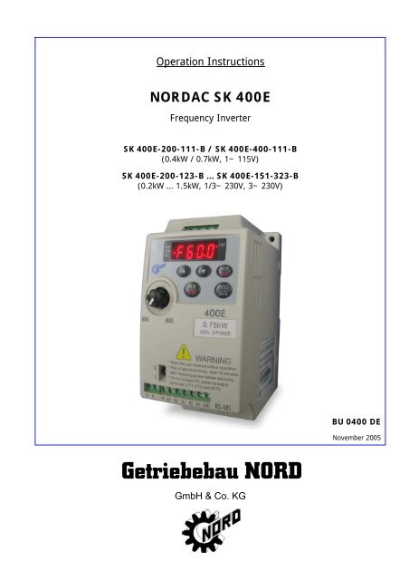
Operation Instructions<br />
<strong>NORD</strong>AC SK 400E<br />
Frequency Inverter<br />
SK 400E-200-111-B / SK 400E-400-111-B<br />
(0.4kW / 0.7kW, 1~ 115V)<br />
SK 400E-200-123-B ... SK 400E-151-323-B<br />
(0.2kW … 1.5kW, 1/3~ 230V, 3~ 230V)<br />
<strong>Getriebebau</strong> <strong>NORD</strong><br />
GmbH & Co. KG<br />
BU 0400 DE<br />
November 2005
<strong>NORD</strong>AC SK400E Manual Safety Instructions<br />
A1<br />
<strong>NORD</strong>AC SK 400E<br />
Frequency Inverter<br />
Safety and operating instructions<br />
for variable speed drives<br />
Thank you for choosing a <strong>NORD</strong>AC SK400E series AC drive. The SK400E series is manufactured<br />
using high-quality components, material and incorporating the latest microprocessor technology<br />
available.<br />
This manual will help with installation, parameter setting, troubleshooting and daily maintenance<br />
of the AC motor drive. To guarantee safe operation of the equipment, read the following safety<br />
guidelines before connecting power to the AC motor drive. Keep this operating manual handy and<br />
distribute to all users for reference.<br />
Important Notes:<br />
� DANGER! AC input power must be disconnected before any maintenance. Do not connect or<br />
disconnect wires while power is applied to the circuit. Only qualified technicians should<br />
perform maintenance on the SK400E.<br />
� CAUTION! There are highly sensitive MOS components on the printed circuit boards. These<br />
components are especially sensitive to static electricity. To avoid damaging these<br />
components, do not touch the circuit boards with metal objects or your bare hands.<br />
� DANGER! A charge may still remain in the DC-link capacitor with hazardous voltages even<br />
after the power has been turned off. To avoid personal injury, do not remove the cover of the<br />
AC drive until all “DISPLAY LED” lights on the digital keypad are off. Please note that there<br />
are live components exposed when the AC drive is open. Be careful to not touch these live<br />
parts.<br />
� CAUTION! Ground the SK400E using the ground terminal. The grounding method must<br />
comply with the laws of the country where the AC drive is to be installed.<br />
� DANGER! The AC drive may be destroyed beyond repair if power is misapplied to the<br />
input/output terminals. Never connect the AC drive output terminals U/T1, V/T2, W/T3<br />
directly to the AC main circuit power supply.
<strong>NORD</strong>AC SK400E Manual<br />
Chapter 1 Receiving and Inspection<br />
This SK400E frequency inverter has gone through rigorous quality control tests at the factory<br />
before shipment. Since many things may happen during shipping, please check for the following<br />
after receiving the frequency inverter.<br />
• Inspect the unit to ensure it was not damaged during shipment.<br />
• Make sure that the part number indicated on the nameplate corresponds with the part number<br />
of your order.<br />
Nameplate Information: Example of 0,4kW 1~/3~ 230V<br />
Inverter type<br />
Input spec.<br />
Output spec.<br />
Output freq, range<br />
Bar code with serial code<br />
Model Explanation:<br />
SK 400E-700-123<br />
Applicable motor capacity: Input voltage:<br />
200: 0.2kW / 1 /4 hp 111: 115V 1 phase<br />
400: 0.4kW / 1 /3 hp 123: 230V 1 or 3 phase<br />
700: 0.7kW / 1 hp 323: 230V 3 phase (only)<br />
151: 1.5kW / 2hp<br />
Series Number Explanation:<br />
79310700 W 5 35 0036<br />
1<br />
Internal production number (0036)<br />
Production week (35 � week 35)<br />
Production year (5 � 2005)<br />
Nord part number (79310700)<br />
If there is any nameplate information not corresponding to your purchase order or any problem,<br />
please contact your distributor.
<strong>NORD</strong>AC SK400E Manual<br />
Dimension<br />
MIN. MAX.<br />
V<br />
I<br />
400E<br />
RS-485<br />
2<br />
UNIT: mm(inch)
<strong>NORD</strong>AC SK400E Manual<br />
Chapter 2 Wiring<br />
Basic Wiring Diagram<br />
Users must connect wiring according to the circuit diagram shown below. Please follow all<br />
applicable local wiring codes, when wiring the SK400E.<br />
Main Circuit Power<br />
R/L1<br />
S/L2<br />
T/L3<br />
MCCB<br />
Factory default settings<br />
Forward/Stop M0<br />
Reverse/Stop<br />
Reset<br />
Multi-step 1<br />
Common Signal<br />
M1<br />
M2<br />
M3<br />
GND<br />
R/L1<br />
S/L2<br />
T/L3<br />
4.7KΩ<br />
4.7KΩ<br />
4.7KΩ<br />
4.7KΩ<br />
Power supply for Potentiometer<br />
+10V 10mA(MAX)<br />
Master Freq. setting 3<br />
+10V<br />
2<br />
Analog voltage VR<br />
AVI<br />
0~ 10VDC<br />
VR: 3K~ 5KΩ<br />
1<br />
Analog current<br />
GND<br />
+18V<br />
+18V<br />
+18V<br />
+18V<br />
3<br />
U/T1<br />
V/T2<br />
W/T3<br />
RA<br />
RC<br />
6←1 RS-485<br />
Communication<br />
port<br />
RJ-11 1:+EV<br />
IM<br />
3~<br />
Multi-function indication<br />
output contacts<br />
120VAC/28VDC 3A<br />
Factory default:<br />
Fault Indication<br />
2:GND<br />
3:SG-<br />
4:SG+<br />
Motor<br />
Main circuit (power)<br />
terminals<br />
Control circuit terminals<br />
Shielded leads<br />
NOTE: Do not plug in a Modem or telephone line to the RS-485 communication port,<br />
permanent damage may result. Terminals 1 & 2 are the power source for the<br />
optional copy keypad and should not be used while using RS-485<br />
communication.<br />
*If the AC Drive model is SK 400E-200-111/123, SK 400E-400-111/123,<br />
SK 400E-700-123, please use power terminals R/L1 and S/L2.<br />
*If the AC Drive model is SK 400E-200-123, SK 400E-400-123,SK 400E-700-123,<br />
3 phase power may be used on R/L1, S/L2, T/L3.<br />
*If the AC Drive model is SK 400E-151-323, single phase power is not allowed.
<strong>NORD</strong>AC SK400E Manual<br />
Main circuit wiring<br />
AC line input terminals<br />
grounding<br />
Single phase models input from R/L1, S/L2<br />
LED display<br />
Frequency<br />
setting knob<br />
Motor capacity<br />
and input power<br />
The signal selection<br />
for AVI to input<br />
DC0~+10V<br />
or 4~20 mA<br />
Control circuit wiring<br />
R/L1 S/L2 T/L3<br />
Wire Gauge:22-24AWG<br />
Torque: 4Kgf-cm<br />
U/T1 V/T2 W/T3<br />
4<br />
400E<br />
UP/DOWN<br />
Function<br />
Display key<br />
Data<br />
Confirmation key<br />
RUN/STOP<br />
RS485<br />
communication<br />
port<br />
Motor connections U/T1, V/T2, W/T3<br />
Grounding<br />
RA RC +10V AVI M0 M1 M2 M3 GND<br />
Relay<br />
Multi-function indication<br />
output contact<br />
(120VAC/DC28V 3A)<br />
Wiring Notes: PLEASE READ PRIOR TO INSTALLATION.<br />
Power for speed setting<br />
Analog Voltage, current<br />
frequency command<br />
Multi-function assistant terminal<br />
Multi-function input selection 1<br />
Multi-function input selection 2<br />
Multi-function input selection 3<br />
Common signal
<strong>NORD</strong>AC SK400E Manual<br />
1. CAUTION: Do not connect the AC input to any of the U/T1, V/T2, W/T3 terminals, as it will<br />
damage the AC drive.<br />
2. WARNING: Ensure all screws are tightened to the proper torque rating.<br />
3. During installation, follow all national and local electrical, construction, and safety codes for<br />
the country the drive is to be installed in.<br />
4. Ensure the appropriate protective devices (circuit breaker or fuses) are connected between<br />
the power supply and AC drive.<br />
5. Make sure that the leads are connected correctly and the AC drive is properly grounded.<br />
(Ground resistance should not exceed 0.1Ω.)<br />
6. Use ground leads that comply with AWG/MCM standards and keep them as short as possible.<br />
7. Multiple SK400E units can be installed in one location. All the units should be grounded<br />
directly to a common ground terminal. The SK400E ground terminals may also be connected<br />
in parallel, as shown in the figure below. Ensure there are no ground loops!<br />
5<br />
Forward<br />
running<br />
8. When the AC drive output terminals U/T1, V/T2, and W/T3 are connected to the motor<br />
terminals U, V, and W, respectively, the motor will rotate counterclockwise (as viewed from the<br />
shaft end of the motor) when a forward operation command is received. To reverse the<br />
direction of motor rotation, switch over any of the two motor leads.<br />
9. Make sure that the power is capable of supplying the correct voltage and required current to<br />
the AC drive.<br />
10. Do not attach or remove wiring when power is applied to the AC drive.<br />
11. Do not monitor the signals on the circuit board while the AC drive is in operation.<br />
12. Route the power and control wires separately, or orthogonal to each other.<br />
13. If a filter is required for reducing EMC (Electro-Magnetic Compatibility), install it as close as<br />
possible to AC drive. EMC can also be reduced by lowering the Carrier Frequency.<br />
14. If the AC drive is installed in the place where a load reactor is needed, install the filter close to<br />
U/T1, V/T2, W/T3 side of AC drive. Do not use a Capacitor or L-C Filter<br />
(Inductance-Capacitance) or R-C Filter (Resistance-Capacitance).<br />
15. When using a GFCI (Ground Fault Circuit Interrupt), select current sensor with minimum<br />
current 200mA, and minimum detection time 0.1-second to avoid nuisance tripping.
<strong>NORD</strong>AC SK400E Manual<br />
Group 0: User Parameters<br />
Chapter 3 Summary of Parameters<br />
Parameters Functions Settings<br />
0-00<br />
0-01<br />
Identity code of drive<br />
(Read only)<br />
Rated current display<br />
(Read only)<br />
�The parameter may be set during operation.<br />
1: 40W<br />
2: 100W<br />
3: 200W<br />
4: 400W<br />
5: 750W<br />
6: 1.5KW<br />
40W: 0.4A<br />
100W: 0.8A<br />
200W: 1.6A<br />
400W: 2.5A<br />
750W: 4.2A<br />
1.5K: 7.0A<br />
6<br />
Factory<br />
Setting<br />
0-02 Parameter reset 10: Reset Parameters to Factory Setting 0<br />
� 0-03 Start-up display of AC 0: F (Frequency command)<br />
drive<br />
1: H (output frequency)<br />
2: U (user-defined unit)<br />
3: A (output current)<br />
0<br />
� 0-04 Display User-defined Unit 0: Display User-Defined Unit (u)<br />
1: Display Counter Value (C)<br />
2: Display Process Operation (1=tt)<br />
3: Display DC-BUS voltage (U)<br />
4: Display output voltage (E)<br />
0<br />
� 0-05 Scaling factor display 0.1 ~ 160 1.0<br />
0-06 Software version Read only #.#<br />
0-07 Password input 0 ~ 999 0<br />
0-08 Password configuration 0 ~ 999 0<br />
Group 1: Basic Parameters<br />
Parameters Functions Settings<br />
Factory<br />
Setting<br />
1-00 Maximum operation Freq. 50.0 ~ 400Hz 60.0<br />
1-01 Maximum setting Freq. 10.0 ~ 400Hz 60.0<br />
1-02 Maximum output voltage 2.0 ~ 255V 220<br />
1-03 Mid-point freq. 1.0 ~ 400Hz 1.0<br />
1-04 Mid-point voltage 2.0 ~ 255V 12.0<br />
1-05 Minimum output freq. 1.0 ~ 60.0Hz 1.0<br />
1-06 Minimum output voltage 2.0 ~ 255V 12.0<br />
1-07 Upper bound of freq. 1 ~ 110% 100<br />
1-08 Lower bound of freq. 0 ~ 100% 0.0<br />
� 1-09 Accel time 1 (Tacc1) 0.1 ~ 600 Sec 10.0<br />
� 1-10 Decel time 1 (Tdec1) 0.1 ~ 600 Sec 10.0<br />
� 1-11 Accel time 2 0.1 ~ 600 Sec 10.0<br />
� 1-12 Decel time 2 0.1 ~ 600 Sec 10.0<br />
� 1-13 JOG Accel time 0.1 ~ 600 Sec 10.0
<strong>NORD</strong>AC SK400E Manual<br />
Parameters Functions Settings<br />
Factory<br />
Setting<br />
� 1-14 JOG Decel time 0.0 ~ 600 Sec 10.0<br />
� 1-15 JOG frequency 1.0Hz~400Hz 6.0<br />
1-16 Auto-accel/decel 0: Linear Accel/Decel<br />
1: Auto accel, linear decel<br />
2: Linear accel, auto decel,<br />
3: Auto Accel/Decel<br />
4: Linear accel. Auto decel, stall prevention<br />
during deceleration<br />
5: Auto accel. Auto decel, stall prevention<br />
during deceleration<br />
0<br />
1-17<br />
S-curve setting in<br />
acceleration<br />
0 ~ 7 0<br />
1-18<br />
S-curve setting in<br />
deceleration<br />
0 ~ 7 0<br />
Group 2: Operation Method Parameters<br />
Parameters Functions Settings<br />
2-00 Source of frequency<br />
command<br />
2-01 Source of operation<br />
command<br />
0: Digital keypad<br />
1: 0 ~ 10V from AVI<br />
2: 4 ~ 20mA from AVI<br />
3: Controlled by V.R on drive<br />
4: RS-485 communication interface<br />
0: By digital keypad<br />
1: By external terminals, keypad STOP<br />
enable<br />
2: By external terminals, keypad STOP<br />
disable<br />
3: By RS-485 communication interface, keypad<br />
STOP enable<br />
4: By RS-485 communication interface, keypad<br />
STOP disable<br />
7<br />
Factory<br />
Setting<br />
0<br />
2-02 Stop method 0: Ramp stop<br />
1: Voltage block<br />
0<br />
2-03 Pulse freq. 3 ~10K Hz 10<br />
2-04 Reverse operation inhibit 0: Enable reverse<br />
1: Disable reverse<br />
2: Disable forward<br />
0<br />
2-05 ACI (4 ~ 20mA)<br />
input loss detection<br />
2-06 Automatic-Start Locking 0: Enable<br />
1: Disable<br />
0: Decel to 0Hz<br />
1: Stop immediately, display EF<br />
2: Run with the last freq.<br />
0<br />
0<br />
0
<strong>NORD</strong>AC SK400E Manual<br />
Group 3: Output Function Parameters<br />
Parameters Functions Settings<br />
Factory<br />
Setting<br />
3-00 Set freq. reached 1.0 ~ 400 Hz 1.0<br />
3-01 Terminal count value 0 ~ 999 0<br />
3-02 Preliminary count value 0 ~ 999 0<br />
3-03 Multi-function (relay 0: not used<br />
8<br />
output)<br />
1: AC drive operational<br />
2: Max. Output Freq. reached<br />
3: Zero Speed<br />
4: Over Torque<br />
5: Base-Block (B.B.)<br />
6: Low Voltage Detection<br />
7: AC Drive Operation Mode<br />
8: Fault Indication<br />
9: Set Freq. reached<br />
10: PLC Program Running<br />
11: PLC Program Step Complete<br />
12: PLC Program Complete<br />
13: PLC Program Operation Pause<br />
14: Terminal Count Value Attained<br />
15: Preliminary Count Value reached<br />
16: Ready State Indicator<br />
Group 4: Input Function Parameters<br />
Parameters Functions Settings<br />
Factory<br />
setting<br />
� 4-00 Potentiometer bias freq. 0.0~350Hz 0.0<br />
� 4-01<br />
Potentiometer bias<br />
polarity<br />
0: positive bias 1: negative bias 0<br />
� 4-02 Potentiometer freq. gain 1~200% 100<br />
4-03 Potentiometer<br />
reverse motion<br />
0: not used<br />
1: reverse motion enable<br />
0<br />
4-04<br />
4-05<br />
4-06<br />
enable 2: forward motion only<br />
Multi-function input<br />
terminal1 (M1)<br />
(d 0~d 20)<br />
Multi-function input<br />
terminal 2(M2)<br />
Multi-function input<br />
terminal 3(M3)<br />
(d 0, d 4~d 20)<br />
0: not used<br />
1: M0: FWD/STOP, M1: REV/STOP<br />
2: M0: RUN/STOP, M1: FWD/REV<br />
3: M0, M1, M2: 3-wire operation control mode<br />
4: External fault, normally open (N.O.)<br />
5: External fault, normally closed (N.C.)<br />
6: RESET<br />
7: multi-step speed command 1<br />
8: multi-step speed command 2<br />
9: jog operation<br />
10: accel/decel speed inhibit<br />
11: first or second accel/decel time selection<br />
12: base-block (B.B.),normally open (N.O.)<br />
13: base-block (B.B.),normally closed (N.C)<br />
4-06 Multi-function input 14: increase master freq.<br />
7<br />
terminal 3(M3)<br />
(d 0, d 4~d 20)<br />
15: decrease master freq.<br />
16: run PLC program<br />
8<br />
1<br />
6<br />
7
<strong>NORD</strong>AC SK400E Manual<br />
Parameters Functions Settings<br />
17: pause PLC<br />
18: counter trigger signal<br />
19: counter reset<br />
20: select ACI/deselect AVI<br />
9<br />
Factory<br />
setting<br />
Group 5: Multi-step Speed and PLC Parameters<br />
Parameters Functions Settings<br />
Factory<br />
Setting<br />
5-00 1 st fixed freq. 0.0 ~ 400Hz 0.0<br />
5-01 2 nd fixed freq. 0.0 ~ 400Hz 0.0<br />
5-02 3 rd fixed freq. 0.0 ~ 400Hz 0.0<br />
5-03 PLC mode 0: Disable PLC operation<br />
1: Execute one program cycle<br />
2: Continuously execute program cycles<br />
3: Execute one program cycle step by step<br />
(separate by STOP)<br />
4: Continuously execute one program cycle step by<br />
step (separate by STOP)<br />
0<br />
5-04 PLC forward/reverse 0 ~ 15 (0: Forward 1: Reverse)<br />
motion<br />
0<br />
5-05 Time duration step 0 0 ~ 65500 Sec 0<br />
5-06 Time duration step 1 0 ~ 65500 Sec 0<br />
5-07 Time duration step 2 0 ~ 65500 Sec 0<br />
5-08 Time duration step 3 0 ~ 65500 Sec 0<br />
Group 6: Protection Parameters<br />
Parameters Functions Settings<br />
Over-Voltage<br />
6-00<br />
Prevention Level<br />
6-01 Over-current<br />
Prevention Level<br />
6-02 Over-torque<br />
detection<br />
6-03<br />
6-04<br />
6-05<br />
6-06<br />
Over-torque<br />
detection level<br />
Over-torque<br />
detection time<br />
Electronic thermal<br />
overload relay<br />
Electronic thermal<br />
characteristic<br />
0:disable<br />
350~410V<br />
0: disable<br />
20~200%<br />
0:disable<br />
1:enable during constant speed operation and<br />
continues until the continuous limit is reached.<br />
2:enabled during constant speed operation and<br />
halted after detection.<br />
3:enabled during accel and continues before<br />
continuous output time limit is reached.<br />
4:enabled during accel and halted after over-torque<br />
detection.<br />
Factory<br />
Setting<br />
390<br />
170<br />
30 ~ 200% 150<br />
0.1 ~ 10.0 Sec 0.1<br />
0: Not used<br />
1: Act with standard motor<br />
2: Act with special motor<br />
30~600 Sec 60<br />
0<br />
0
<strong>NORD</strong>AC SK400E Manual<br />
Parameters Functions Settings<br />
6-07 Present fault record<br />
6-08<br />
Second most recent<br />
fault record<br />
6-09<br />
Third most recent<br />
fault record<br />
6-10<br />
Forth most recent<br />
fault record<br />
6-11<br />
Fifth most recent<br />
fault record<br />
6-12<br />
Sixth most recent<br />
fault record<br />
Group 7: Motor Parameters<br />
0: No fault occurred<br />
1: oc (over current)<br />
2: ov (over voltage)<br />
3: oH (over heat)<br />
4: oL (over load)<br />
5: oL1 (electronic thermal)<br />
6: EF (external fault)<br />
7: Reserved<br />
8: Reserved<br />
9: ocA (current exceed during acceleration)<br />
10: ocd (current exceed during deceleration)<br />
11: ocn (current exceed during steady state)<br />
10<br />
Factory<br />
Setting<br />
0<br />
Parameters Functions Settings<br />
Factory<br />
Setting<br />
� 7-00 Motor rated current 30~120 % 85<br />
� 7-01 Motor no-load current 0 ~ 90 % 50<br />
� 7-02<br />
Torque<br />
compensation<br />
0 ~ 10 1<br />
� 7-03 Slip compensation 0.0 ~ 10.0 0.0<br />
Group 8: Special Parameters<br />
Parameters Functions Settings<br />
Factory<br />
Setting<br />
8-00 DC braking voltage level 0 ~ 30% 0<br />
8-01<br />
DC braking time during<br />
start-up<br />
0.0 ~ 60.0 Sec 0.0<br />
8-02<br />
DC braking time during<br />
stopping<br />
0.0 ~ 60.0 Sec 0.0<br />
8-03 Start-point for DC braking 0.0 ~ 400.0 Sec 0.0<br />
8-04 Momentary power loss 0: Stop operation after momentary power<br />
loss.<br />
1: Continues after momentary power loss,<br />
speed search starts with master freq.<br />
2: Continues after momentary power loss,<br />
speed search starts with min. output<br />
freq.<br />
0<br />
8-05<br />
Max. allowable power loss<br />
0.3 ~ 5.0 Sec<br />
time<br />
2.0<br />
8-06 B.B. time for speed search 0.3~5.0 Sec 0.5<br />
8-07<br />
Max. speed search current<br />
level<br />
30~200% 150<br />
8-08 Skip freq. 1 upper bound 0.0~400 Hz 0.0<br />
8-09 Skip freq. 1 lower bound 0.0~400 Hz 0.0<br />
8-10 Skip freq. 2 upper bound 0.0~400 Hz 0.0<br />
8-11 Skip freq. 2 lower bound 0.0~400 Hz 0.0<br />
8-12 Skip freq. 3 upper bound 0.0~400 Hz 0.0<br />
8-13 Skip freq. 3 lower bound 0.0~400 Hz 0.0
<strong>NORD</strong>AC SK400E Manual<br />
Parameters Functions Settings<br />
Factory<br />
Setting<br />
8-14 Auto restart after fault 0~10 0<br />
8-15 AVR function 0: AVR function enable<br />
1: AVR function disable<br />
2: AVR function disable when decel<br />
2<br />
8-16 Dynamic braking voltage 350 ~ 450V 380<br />
8-17 DC braking lower bound limit 0.0 ~ 400 Hz 0.0<br />
Group 9: Communication Parameters<br />
Parameters Functions Settings<br />
Factory<br />
Setting<br />
� 9-00 Communication address 1 ~ 247 1<br />
� 9-01 Transmission speed 0: Baud rate 4800<br />
1: Baud rate 9600<br />
2: Baud rate 19200<br />
1<br />
� 9-02 Transmission fault 0: Warn and continue running<br />
0<br />
treatment<br />
1: Warn and ramp to stop<br />
2: Warn and coasting stop<br />
3: No warn and keep running<br />
� 9-03<br />
Modbus communication<br />
watchdog timer<br />
0: Disable<br />
1~20: 1 ~ 20 Sec<br />
0<br />
� 9-04 Communication<br />
protocol<br />
ASCII<br />
mode<br />
RTU<br />
mode<br />
11<br />
0: 7,N,2<br />
1: 7,E,1<br />
2: 7,O,1<br />
3: 8,N,2<br />
4: 8,E,1<br />
5: 8,O,1<br />
6: 8,N,2<br />
7: 8,E,1<br />
8: 8,O,1<br />
0
<strong>NORD</strong>AC SK400E Manual<br />
CHAPTER 4 Troubleshooting and Fault Information<br />
The SK400E AC drive has a comprehensive fault diagnostic system that includes several different<br />
alarms and fault messages. Once a fault is detected, the corresponding protective functions will<br />
be activated. The following faults are displayed on the AC drive digital keypad. The six most<br />
recent faults can be read on the digital keypad display by viewing Pr.6-07 to Pr.6-12.<br />
NOTE: faults can be cleared by pressing the Reset key on the keypad or Input Terminal.<br />
Common Problems and Solutions:<br />
Fault<br />
Name<br />
Fault Descriptions Corrective Actions<br />
The AC drive detects an abnormal<br />
increase in current.<br />
The AC drive detects that the DC bus<br />
voltage has exceeded its maximum<br />
allowable value.<br />
The AC drive temperature sensor<br />
detects excessive heat.<br />
The AC drive detects that the DC bus<br />
voltage has fallen below its minimum<br />
value.<br />
Internal electronic overload trip<br />
The external terminal EF-GND goes<br />
from OFF to ON.<br />
Motor overload. Check the<br />
parameter settings ( Pr.6-03 to<br />
Pr.6-05)<br />
1. Check whether the motors horsepower<br />
corresponds to the AC drive output power.<br />
2. Check the wiring connections between the<br />
AC drive and motor for possible short circuits.<br />
3. Increase the Acceleration time (Pr.1-09,<br />
Pr.1-11).<br />
4. Check for possible excessive loading<br />
conditions at the motor.<br />
5. If there are any abnormal conditions when<br />
operating the AC drive after the short-circuit<br />
is removed, the drive should be sent back to<br />
12<br />
manufacturer.<br />
1. Check whether the input voltage falls within<br />
the rated AC drive input voltage.<br />
2. Check for possible voltage transients.<br />
3. Bus over-voltage may also be caused by<br />
motor regeneration. Increase the decel time.<br />
1. Ensure that the ambient temperature falls<br />
within the specified temperature range.<br />
2. Make sure that the ventilation holes are not<br />
obstructed.<br />
3. Remove any foreign objects on the heat sink<br />
and check for possible dirty heat-sink fins.<br />
4. Provide enough spacing for adequate<br />
ventilation.<br />
Check whether the input voltage falls within the<br />
rated AC drive’s input voltage.<br />
1. Check for possible motor overload.<br />
2. Check electronic thermal overload setting.<br />
3. Increase motor capacity.<br />
4. Reduce the current level so that the drive<br />
output current does not exceed the value set<br />
by the Motor Rated Current Pr.7-00.<br />
When external terminal EF-GND is closed, the<br />
output will be turned off. (under N.O.��E.F.)<br />
1. Reduce the motor load.<br />
2. Adjust the over-torque detection setting to an<br />
appropriate setting.
<strong>NORD</strong>AC SK400E Manual<br />
Fault<br />
Name<br />
Fault Descriptions Corrective Actions<br />
Over-current during acceleration:<br />
1. Short-circuit at motor output.<br />
2. Torque boost too high.<br />
3. Acceleration time too short.<br />
4. AC drive output capacity is too<br />
small.<br />
Over-current during deceleration:<br />
1. Short-circuit at motor output.<br />
2. Deceleration time too short.<br />
3. AC drive output capacity is too<br />
small.<br />
Over-current during steady state<br />
operation:<br />
1. Short-circuit at motor output.<br />
2. Sudden increase in motor loading.<br />
3. AC drive output capacity is too<br />
small.<br />
Internal memory IC can not be<br />
programmed.<br />
Internal memory IC can not be read.<br />
1. Check for possible poor insulation at the<br />
output line.<br />
2. Decrease the torque boost setting in Pr.7-02.<br />
3. Increase the acceleration time.<br />
4. Replace with the AC drive with one that has a<br />
13<br />
higher output capacity (next HP size).<br />
1. Check for possible poor insulation at the<br />
output line.<br />
2. Increase the deceleration time.<br />
3. Replace with the AC drive with one that has a<br />
higher output capacity (next HP size).<br />
1. Check for possible poor insulation at the<br />
output line.<br />
2. Check for possible motor stall.<br />
3. Replace with the AC drive with one that has a<br />
higher output capacity (next HP size).<br />
1. Switch off power supply.<br />
2. Check whether the input voltage falls within<br />
the rated AC drive input voltage.<br />
3. Switch the AC drive back on.<br />
1. Check the connections between the main<br />
control board and the power board.<br />
2. Reset drive to factory defaults.<br />
Drive’s internal circuitry abnormal.<br />
1. Switch off power supply.<br />
2. Check whether the input voltage falls within<br />
the rated AC drive input voltage. Switch on<br />
the AC drive.<br />
Hardware protection failure Return to the factory.<br />
Software protection failure Return to the factory.<br />
Auto accel/decel failure<br />
Don’t use the function of auto acceleration/<br />
Communication Error<br />
External Base Block.<br />
AC drive output is turned off.<br />
The AC drive detects excessive drive<br />
output current.<br />
deceleration.<br />
1. Check the connection between the AC drive<br />
and computer for loose wires.<br />
2. Check if the communication protocol is<br />
properly set.<br />
1. When the external input terminal (B.B) is<br />
active, the AC drive output will be turned off.<br />
2. Disable this connection and the AC drive will<br />
begin to work again.<br />
1. Check whether the motor is overloaded.<br />
2. Reduce torque compensation setting as set in<br />
Pr.7-02.<br />
3. Increase the AC drive’s output capacity.<br />
4. Note: The AC drive can withstand up to 150%<br />
of the rated current for a maximum of 60<br />
seconds.
<strong>NORD</strong>AC SK400E Manual<br />
Technical Specifications<br />
Input Voltage Class 115V 230V<br />
Model Number 400E 200 400 200 400 700 151<br />
Applicable Motor Output (kW) 0.2 0.4 0.2 0.4 0.7 1.5<br />
Output Rating<br />
Power<br />
Control<br />
Characteristics<br />
Operating Characteristics<br />
Environment<br />
Rated Output Capacity (KVA) 0.6 1.0 0.6 1.0 1.6 2.7<br />
Rated Output Current (A) 1.6 2.5 1.6 2.5 4.2 7.0<br />
Max. Output Voltage (V)<br />
3-phase corresponds<br />
to double input<br />
voltage<br />
Three-phase corresponds to input voltage<br />
Rated Frequency (Hz) 1.0~400Hz<br />
Rated Input Current (A) 6 9 4.9/1.9 6.5/2.7 9.7/5.1 �/9<br />
Input voltage Tolerance<br />
Single phase<br />
90~132V 50/60Hz<br />
Frequency tolerance ±5%<br />
14<br />
Single / 3-phase<br />
180~264V 50/60Hz<br />
3-phase<br />
180~264V<br />
50/60Hz<br />
Control system SVPWM (Sinusoidal Pulse Width Modulation, carried frequency 3kHz~10kHz)<br />
Output Frequency Resolution 0.1Hz<br />
Torque Characteristics<br />
Including the auto-torque, auto-slip compensation, starting torque can be 150% at<br />
5 Hz<br />
Overload Endurance 150% of rated current for 1 minute<br />
Accel/Decel Time 0.1~600Sec. (can be set individually)<br />
V/F pattern V/F pattern adjustable<br />
Stall Prevention Level 20~200%, setting of Rated Current<br />
Keypad Setting by ▲▼ keys or V.R<br />
Frequency<br />
Setting External Signal<br />
Potentiometer-5KΩ/0.5W, DC 0 ~ +10V (input impedance 47KΩ), 4~20mA (output<br />
impedance 250Ω), multi-function inputs1 to 3 (3steps, JOG, UP/DOWN<br />
command), communication setting<br />
Operation<br />
Setting<br />
Keypad Setting by RUN//STOP keys<br />
Signal External Signal<br />
M0,M1,M2,M3 can be combined to offer various modes of operation, RS-485<br />
communication port<br />
Multi-function Input Signal<br />
Multi-step selection 0 to 3, Jog, accel/decel inhibit, first/second accel/decel switch,<br />
counter, PLC Operation, external Base Block (NC,NO) selection<br />
Multi-function Output Signal<br />
AC Drive Operating, Frequency Attained, Non-zero speed, Base Block, Fault<br />
Indication, Local/Remote indication, PLC Operation indication.<br />
AVR, S-curve, Over-Voltage Stall Prevention, DC Braking, Fault Records,<br />
Other Function<br />
Adjustable Carried Frequency, Starting Frequency Setting of DC Braking ,<br />
Over-Current Stall Prevention, Momentary Power Loss restart, Reverse Inhibition,<br />
Frequency Limits, Parameter Lock/Reset<br />
Protection<br />
Over Voltage, Over Current, Under Voltage, Overload, Electronic thermal,<br />
Overheating, Self-testing<br />
Other Including EMI Filter<br />
Cooling Forced air-cooling<br />
Installation Location Altitude 1,000 m or below, keep from corrosive gasses, liquid and dust<br />
Ambient Temperature -10 -40 (Non-Condensing and not frozen)<br />
Storage Temperature -20 to 60<br />
Ambient Humidity Below 90%RH (non-condensing)<br />
Vibration 9.80665m/s 2 (1G) less than 20Hz, 5.88m/s 2 (0.6Gat) 20 to 50Hz
<strong>NORD</strong>AC SK400E Manual<br />
<strong>Getriebebau</strong> <strong>NORD</strong> GmbH & Co. KG<br />
Rudolf- Diesel- Str. 1 ⋅ 22941 Bargteheide<br />
Phone: +49-4532-401-0<br />
Fax: +49-4532-401-254<br />
info@nord-de.com<br />
www.nord.com<br />
15<br />
<strong>NORD</strong> Global<br />
DRIVESYSTEMS<br />
www.nord.com<br />
Mat. Nr. 608 40 02 / 4605