OPERATING INSTRUCTIONS NORDAC Frequency Inverters
OPERATING INSTRUCTIONS NORDAC Frequency Inverters
OPERATING INSTRUCTIONS NORDAC Frequency Inverters

You also want an ePaper? Increase the reach of your titles
YUMPU automatically turns print PDFs into web optimized ePapers that Google loves.
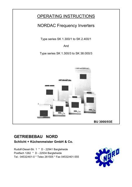
GETRIEBEBAU NORD<br />
<strong>OPERATING</strong> <strong>INSTRUCTIONS</strong><br />
<strong>NORDAC</strong> <strong>Frequency</strong> <strong>Inverters</strong><br />
Type series SK 1.300/1 to SK 2.400/1<br />
And<br />
Type series SK 1.300/3 to SK 38.000/3<br />
Schlicht + Küchenmeister GmbH & Co.<br />
Rudolf-Diesel-Str. 1 * D - 22941 Bargteheide<br />
Postfach 1262 * D - 22934 Bargteheide<br />
Tel.: 04532/401-0 * Telex 261505 * Fax 04532/401-555<br />
BU 3000/93E
Table of contents<br />
Page<br />
1.0 General 1<br />
1.1 Delivery 1<br />
1.2 Scope of delivery 1<br />
1.3 Installation and operation 1<br />
2.0 Installation 2<br />
3.0 <strong>Frequency</strong> inverter dimensions 3<br />
3.1 Braking chopper dimensions 3<br />
4.0 Connection 4<br />
4.1 Power section 4<br />
4.1.1 Type SK 1.300/1 - SK 2.400/1 4<br />
4.1.2 Type SK 1.300/3 - SK 38.000/3 4<br />
4.1.3 Additional measures 4<br />
4.2 Control section 5<br />
4.2.1 Control terminal strip 5<br />
4.2.2 Control inputs 6<br />
5.0 Operation and displays 12<br />
5.1 Setting and display facilities 13<br />
5.2 Description of settings and displays 14<br />
6.0 Commssioning 22<br />
6.1 Parameter record 23<br />
7.0 Braking chopper 24<br />
7.1 Technical data 24<br />
7.2 Installation instructions 24<br />
7.3 Settings 24<br />
7.4 Selection criteria 24<br />
8.0 Failure and faults 26<br />
9.0 Speed controller 27<br />
10.0 Mains filter 29<br />
10.1 Radio interference suppression 29<br />
10.2 Effect on other consumers 30<br />
10.3 Line capacitances (motor cable) 30<br />
10.4 Output filters 30<br />
10.5 Regulations 30<br />
11.0 Technical data 31<br />
T.-Nr.: 06063082<br />
Stand: 42/93
1.0 General<br />
<strong>NORDAC</strong> frequency <strong>Inverters</strong> are sine-related pulse-width modulated inverters with a constant DC link voltage.<br />
The inverters can be used for infinitely variable adjustment of the speeds of 3-phase motors with low loss.<br />
Use: - For single-motor and multiple-motor drives<br />
Output currents and DC link voltages are detected very - <strong>NORDAC</strong> frequency inverters are short-circuit proof,<br />
quickly and precisely. ground-fault resistant and stable at no load.<br />
The inverters permit 1.5 times the rated current for - There is no immediate switch-off in the event of overload 30<br />
seconds. of brief short-circuit<br />
The settings on the <strong>NORDAC</strong> <strong>Frequency</strong> Inverter are made with keys and displays in plain language (in dialogue with operater).<br />
Advantages: - Operating data in digital values<br />
- Precisely reproducible at any time and with any unit of the<br />
same series<br />
- Analogue adjustment facilities no longer present<br />
Separate braking chopper: - To be used for recovery of high regenerative braking energy<br />
to the DC link<br />
- To be connected to the + and - terminals (even afterwards)<br />
1.1 Delivery<br />
Examine the device immediately after delivery for transport damage such as distortions or loose parts.<br />
If damage has occured: - Contact the transport company without<br />
delay.<br />
- Make a careful note of damage.<br />
Important! this applies even if the packaging is undamaged.<br />
1.2 Scope of delivery<br />
Standard version : - IP 20 panel mounting unit<br />
with built-in line choke and output filter for<br />
compensating for line capacitances (see point 10.3)<br />
- Operating instructions<br />
- Output filters (see point 10.4)<br />
Accessoires available: - Braking chopper<br />
with integrated braking resistor (see point 7)<br />
- Additional choke for higher line capacitances<br />
(see point 10.3)<br />
- Special versions, e.g. for frequencies above 120 Hz<br />
1.3 Installation and operation<br />
Installation : - Installation by qualified personnel only<br />
- Observe local regulations applicable to installation of<br />
electrical systems<br />
- Adhere to accident prevention regulations<br />
- Take the usual safety measures<br />
Before switching on the unit: - Re-attach all covers and guards<br />
- Reconnect all plugs (---> push-locked terminal strips)<br />
- Also reconnect all plugs not being used<br />
CAUTION ! DANGER !<br />
=========================<br />
The power section can still be live up to 2 minutes after being disconnected from the mains.<br />
Inverter terminals, motor supply cables, and motor terminals can still be live.<br />
Touching exposed or unconnected terminals, cables, or parts of the device can lead to serious injuries or even death!<br />
Important Note ! Caution !<br />
==============================<br />
Motor stop owing to:<br />
- Electronic disable * Inverter terminals, motor leadwire, and motor<br />
- Terminal short-circuit terminals are still live !<br />
- Drive jammed * The motor may start up on its own if the inverter is not<br />
disconnected from the mains.<br />
The electronic disable facility is not a device as defined by German Accident Prevention Regulations (UVV).<br />
The terminals on the control board are not at mains potential.
2.0 Installation<br />
The units require adequate ventilation. Minimum clearances between the individual units must be observed for this purpose.<br />
The heated air is to be carried off above the devices!<br />
Front view Side view<br />
If the mountig surface does not form a rear surface --> fit a baseplate<br />
Type a b c d<br />
SK 1.300/.; SK 1.900/. 10 10 100 50<br />
SK 2.400/1 ; SK 3.600/3; SK 5.900/3 10 10 100 50<br />
SK 7.500/3; SK 10.000/3; SK 15.000/3 10 10 100 50 All dimensions in mm<br />
SK 20.000/3 10 10 150 80<br />
SK 30.000/3; SK 38.000/3 10 10 200 100<br />
Several devices one above another --> Take precautions against heat build-up (e.g. air baffles)<br />
2<br />
not allowed
3.0 <strong>Frequency</strong> inverter dimensions<br />
Version shown: IP 20<br />
SK 1.300 ... SK 15.000/3 SK 20.000/3 ... 38.000/3<br />
Detail:<br />
Fixing hole<br />
Type T B L a b c e e1 e2 f f1<br />
SK 1.300/1 185 203 205 180 182 10 5,2<br />
SK 1.900/1 185 203 250 180 227 10 5,2<br />
SK 2.400/1 185 203 290 180 265 10 5,2<br />
SK 1.300/3 185 203 205 180 182 10 5,2<br />
SK 1.900/3 185 203 250 180 227 10 5,2<br />
SK 3.600/3 185 203 290 180 265 10 5,2<br />
SK 5.900/3 185 203 355 180 326 12 6,2<br />
SK 7.500/3 + SK 10.000/3 185 203 430 180 401 12 6,2<br />
SK 15.000/3 250 268 520 235 484 14 6,2<br />
SK 20.000/3 250 319 642 600 20 22 299 540 280 12 6,2<br />
SK 30.000/3 292 353 728 680 25 20 333 620 320 12 6,2<br />
SK 38.000/3 252 440 647 595 25 73 420 472 236 12 6,2<br />
3.1 Braking chopper dimensions<br />
All dimensions in mm<br />
All dimensions in mm<br />
Type T B L e e1 f<br />
SK 3/350/32 175 100 85 90 64 5,5<br />
SK 6/350/64 175 100 85 90 64 5,5<br />
SK 3/600/64 175 100 85 90 64 5,5<br />
SK 6/600/180 185 222 110 200 100 5,5<br />
SK 12/600/360 185 222 110 200 100 5,5<br />
SK 24/600/720 185 222 170 200 160 5,5<br />
SK 40/600 150 150 195 128 175 6,5<br />
SK 80/600 150 150 195 128 175 6,5<br />
SK 130/600 150 150 195 128 175 6,5<br />
3
4.0 Connection<br />
4.1 Power section<br />
4.1.1 Typ SK 1.300/1 - SK 2.400/1<br />
Connection for mains, braking chopper and motor - via screw-type push-lock terminal strips on the lower output stage<br />
board<br />
Maximum line cross-sectional area - 2,5 mm 2<br />
Keep earth connection (PE) at very low ohms.<br />
<strong>NORDAC</strong> SK 1.300/1...SK 2.400/1 - Please mind the line lengths!<br />
Mains Braking chopper Motor<br />
SK 3/350/22 +<br />
SK 6/350/64<br />
4.1.2 Typ SK 1.300/3 - SK 38.000/3<br />
* if required<br />
- Cf. point 10.3<br />
Connection for mains, braking chopper and motor SK 1300/3 to SK 5900/3<br />
Maximum line cross-sectional area - 2,5 mm 2 via screw-type push-lock terminal strip on the<br />
Keep earth connection (PE) at very low ohms lower output stage board<br />
SK 7.500/3 and 10.000/3<br />
<strong>NORDAC</strong> SK 1.300/3...SK 38.000/3 - 4,0 mm 2 via screw-type terminal strip on the line and output choke<br />
Mains Braking chopper Motor<br />
SK 3/600/64...<br />
SK 24/600/720<br />
SK 40/600 ... SK 130/600<br />
(-) (+) (PE)<br />
SK 15.000/3 to SK 30.000/3<br />
- 10 mm 2 via screw-type terminal strip on the line and output choke<br />
SK 38.000/3<br />
- 16 mm 2 via screw-type terminal strip on the line and output choke<br />
* if required - Please mind the line lengths!<br />
- Cf. point 10.3<br />
braking resistance<br />
4.1.3 Additional measures (compare point 10.2, 10.3 and 10.4)<br />
Types SK 1.300/1 to SK 2.400/1 and SK 1.300/3 to SK 38.000/3<br />
4<br />
Also for braking chopper connection (recommended < 10m)<br />
230 / 240 V<br />
50 / 60 Hz<br />
auxiliary voltage
4.2 Control section<br />
Connection for the control lines - 22-pole control terminal strip on the mains power supply board,<br />
subdivided into three blocks<br />
Maximum connection cross sectional - 1,5 mm 2<br />
area<br />
4.2.1 Control terminal strip Setpoint - shield lines.<br />
(short lines twisted at least)<br />
Reference potential for the setpoints (GND)<br />
Setpoint - 10 V / 0 / + 10 V DC<br />
Setpoint - 10 V / 0 / + 10 V DC<br />
Setpoint 0 (4) ... 20 mA<br />
+ 10 V reference voltage<br />
Reversing<br />
Electronic release<br />
Fault acknowledgement<br />
PTC thermistor/tempearture sensor<br />
PTC thermistor/temperature sensor<br />
Parameter switchover input 1<br />
Parameter switchover input 2<br />
Digital frequency output<br />
Reference potential for the control inputs<br />
(GND)<br />
Tachogenerator + *)<br />
Tachogenerator - *)<br />
max.load rating 240 V ~ / 60 V = ; 0,8 A Multifunction relay<br />
max.load rating 240 V ~ / 60 V = ; 0,8 A <strong>Frequency</strong> signalling relay<br />
max.load rating 240 V ~ / 60 V = ; 0,8 A Fault signalling relay<br />
*) Option<br />
5
4.2.2 Control inputs<br />
Terminal Function / Notes Data Suggested circuit<br />
6<br />
General S1 to the left<br />
The push-lock terminal strip for the control inputs<br />
is located at the power supply board.<br />
If you remove the front cover, you will find<br />
switches S1 and S3 on this board, by means of<br />
which the inverter can be adjusted to various<br />
control signals.<br />
S 3 S 1<br />
8-pole DIP switch slider switch,<br />
two positions<br />
S 1 : Switchcover of signal level at<br />
terminals 6, 7, 8, 11, 12<br />
S 1 to the left<br />
Control commands<br />
a) potential free contacts<br />
b) Transistor (npn)<br />
open collector<br />
S 1 to the right<br />
----> works setting<br />
Control commands as external signal tension from +15 VDC S1 to the right<br />
e.g. as PLC-control to +30 VDC<br />
S 3 : Switchover setpoint actual point<br />
OFF ON<br />
Terminal 1 high- Terminal 1 lowohms<br />
against GND ohms against GND<br />
rpm-regulation <strong>Frequency</strong> control<br />
*)<br />
4 ... 20 mA 0 ... 20 mA<br />
0 ... 20 mA 4 ... 20 mA<br />
Negative set- +/- Setpoint<br />
point switched active<br />
off<br />
frequency rpm-regulation<br />
control *)<br />
Actual point area Actual point area<br />
30V to 100V *) 10V to 40V *)<br />
not connected<br />
(N.C.)<br />
*) PI controller option<br />
(see point 9.0)
Terminal Function / Notes Data Suggested circuit<br />
1 S 3 - 1 : ON<br />
- Terminal 1 is linked to Terminal 14 (GND):<br />
Setpoints at Terminal 2 and Terminal 3 are<br />
added together<br />
S 3 - 1 : OFF<br />
- Terminal 1 is at high ohms against GND approx.130 kOhm<br />
- Inputs Terminal 1 and Terminal 2 or<br />
Terminal 1 and Terminal 3 are working<br />
as differential inputs. The differential<br />
inputs cannot both be used at the same<br />
time as linear addition of their setpoints<br />
would then not be possible.<br />
The differential amplifier is ineffective<br />
if Terminal 14 and Terminal 1 are both given<br />
the same potential by the external control<br />
unit, e.g. protection lead (PE) or ext. GND<br />
2 or 3 Setpoints must be free of interference. Input resistance<br />
Check with oscilloscope if necessary approx 130 kOhm<br />
acceptable: not acceptable:<br />
If necessary, lay the setpoint-lines as shielded<br />
wiring. The shield must be connected on one side<br />
to GND or PE.<br />
The setpoint-lines should be twisted if they are<br />
short and not shielded.<br />
S 3 - 5 : ON -10V ... 0 ...+10V<br />
with direction recognition from the polarity of the<br />
setpoint.<br />
The direction of rotation at Terminal 6 then must not<br />
be approached.<br />
Setpoint Terminal 6 Direction<br />
0 ... + 10V 0 clockwise<br />
0 ... + 10V I counter-clockwise<br />
0 ... - 10V 0 counter-clockwise<br />
0 ... - 10V I counter-clockwise<br />
0 = not approached<br />
I = approached<br />
S 3 - 5 : OFF<br />
Direction change only possible by signal 0 ... + 10V<br />
to Terminal 6<br />
Setpoint Terminal 6 Direction<br />
0 ... + 10 0 clockwise<br />
0 ... + 10 I counter-clockwise<br />
0 ... - 10 0 counter-clockwise,<br />
with the minimum<br />
frequency set<br />
0 ... - 10 I counter-clockwise,<br />
with the minimum<br />
frequency set<br />
Aim: No unitentional reversal will occur at<br />
setpoints with negative upper waves,<br />
alternatively selection of direction at<br />
Terminal 6 will not be obstructed. 7
Terminal Function / Notes Data Suggested circuit<br />
2 or 3 a) Setpoint setting<br />
with potentiometer<br />
without direction recognition Poti<br />
S 3 - 1 : ON or OFF min. 1 kOhm<br />
S 3 - 5 : OFF max. 20 kOhm<br />
b) as for a), but<br />
with start/stop by contact-setting<br />
Contact open: Setpoint = 0 = fmin.<br />
Contact closed: Set setpoint<br />
equal to/less than fmax.<br />
c) Setpoint with fixed internal setting<br />
without direction recognition<br />
S 3 - 1 : ON or OFF<br />
S 3 - 5 : OFF<br />
Contact from 2(3) to 1: Setpoint = 0 = fmin.<br />
Contact from 2(3) to 5: Setpoint = 10V = fmax.<br />
Note: further setpoints fmin. and fmax.<br />
can also be programmed into the<br />
parameter sets 1 to 4 (Point 11/12)<br />
d) Setpoint setting by an external voltage source<br />
without direction recognition 0 ... +10V<br />
S 3 - 1: ON or OFF<br />
S 3 - 5: OFF<br />
e) as for d), but<br />
with direction recognition -10V...0...+10V<br />
S 3 - 1 : ON or OFF<br />
S 3 - 5 : ON<br />
f) as for d) or e) but unity<br />
control-factor setting at 5 V 0 ... +5V<br />
S 3 - 1 : ON -5 ... 0 ... +5V<br />
S 3 - 5 : OFF or ON<br />
g) Several setpoints via potentiometers Poti:<br />
without direction recognition min. 2 kOhm<br />
S 3 - 1 : ON max. 20 kOhm<br />
S 3 - 5 : OFF<br />
K 1 K 2 Setpoint<br />
open open 0 = fmin.<br />
closed open Setpoint 1<br />
open closed Setpoint 2<br />
closed closed Sum of internal limit:<br />
Setpoint 1 approx 11 V<br />
and<br />
Setpoint 2<br />
h) Setpoint setting via potentiometers with direction<br />
recognition (external voltage source needed)<br />
S 3 - 1 : ON or OFF<br />
S 3 - 5 : ON<br />
4 Setpoint from marked current 0(4) ... 20 mA<br />
S 3 - 1 : ON Load: 250 Ohm<br />
0 ... 20 mA : S 3 - 3 ON<br />
S 3 - 4 OFF<br />
4 ... 20 mA : S 3 - 3 OFF<br />
S 3 - 4 ON<br />
5 Reference voltage for setpoint supply +10V, +/- 1 %<br />
max. 12 mA<br />
(short-circuit proof)<br />
8
Terminal Function / Notes Data Suggested circuit<br />
Terminals 6-14 generally<br />
The control signals at Terminals 6, 7, 8, 11<br />
and 12 relate to the reference potential GND<br />
at Terminal 14.<br />
Switch S1 to the left<br />
a) Contacts potential free<br />
or<br />
b) Transistors with<br />
open collector<br />
If switch S1 is set to the right<br />
a) outside voltage +15 ... + 30V<br />
Note:<br />
Control commands can be switched to several inputs<br />
at the same time, e.g. direction and parameter<br />
switchover, with one command or output<br />
a) Contact potential free<br />
b) Voltage signal from PLC if the loading is<br />
permissible (see general points on control<br />
terminal strip)<br />
6 Reversing via control command<br />
S 3 - 5 : OFF or ON Setpoint:<br />
0 ... + 10V<br />
The inverter brakes with the braking ramp, or<br />
changes the field rotation direction, and 0(4) ... 20 mA<br />
accelerates to the high-speed ramp<br />
(see ramp diagramm)<br />
7 Electronic Release<br />
Parameter "rampdown" (menue point 20) is programmed<br />
at "on" and electronic is disabled:<br />
- the motor is run down to braking ramp<br />
- all other functions will be finished as set<br />
(e.g. setpoint delay and DC braking)<br />
- finally electronic release will lock output<br />
automatically<br />
Aim:<br />
A completely closed working cycle can only be<br />
controlled with the following switches set:<br />
- setpoint (Terminal 2 or 3, function c)<br />
- direction recognition (Terminal 6)<br />
- electronic release (Terminal 7)<br />
t<br />
If an electromecanical brake is existing:<br />
- control of external brake relay with help of<br />
frequency signalling relay (terminal 19/20)<br />
fset=2,0 Hz and setpoint delay<br />
t = 0,02 - 0,3 s acc. to reaction time of the brake.<br />
Caution ! Danger !<br />
Even though ELECTRONIC RELEASE is locked and<br />
motor is de-energized, the motor is not electrically<br />
insulated from the mains. Working on<br />
the inverter power terminals, motor leadwire, or<br />
motor terminals is very dangerous ! Take care!<br />
9
Terminal Function / Notes Data Suggested circuit<br />
8 Fault acknowledgement<br />
A fault disables the inverter<br />
Display: - Fault<br />
Released by: - acknowledgement of fault<br />
or<br />
switching main OFF\ON<br />
Presupposing: - the fault is no longer present<br />
or has been cleared<br />
Display flashes: - Acknowledgement possible<br />
Caution !<br />
If the cause of the fault has been put right, or<br />
if it is no longer present,and is then acknowledged,<br />
the drive starts to run again as soon as control<br />
is released and setpoint reset. Acknowlegdment input<br />
should not be used during operation. Undesirable<br />
drive movements could result.<br />
9/10 Connection for temperature sensor<br />
a) PTC thermistor temperature sensor Response<br />
threshold<br />
approx. 5 kOhm<br />
b) Floating temperature switch<br />
c) Bridge terminals 9 and 10 if no temperature<br />
sensors are existing<br />
11/12 Options: Parameter set 1 - 4<br />
parameter set Term. 11 Term.12<br />
1 0 0<br />
2 I 0<br />
3 0 I<br />
4 I I<br />
0 = open input<br />
I = input approached<br />
If the parameter sets are switched over during<br />
operation, the new parameters selected come<br />
into effect at once. The transition to a new<br />
frequency is made with the acceleration and<br />
braking ramps of the parameter set selected.<br />
13 Digital frequency output<br />
Pulse duty factor 1 : 1 and L = GND<br />
<strong>Frequency</strong> duty factor 1 : 1 H = + 15 V<br />
14 Reference potential GND<br />
for control signals Terminals 6 to 13<br />
10<br />
S 3 - 1 : ON ---> Terminal 1 is linked with<br />
Terminal 14
Terminal Function / Notes Data Suggested circuit<br />
15/16 Terminals for tachogenerator<br />
(speed controller option)<br />
15 Connection of the positive voltage of<br />
the tachogenrator<br />
The polarity at the terminals must remain<br />
the same in the case of reversing the motor<br />
DIP switch at the power supply board:<br />
frequency- Speedcontrolled<br />
controlled<br />
S 3 - 1 ON (OFF) ON<br />
S 3 - 2 ON OFF<br />
S 3 - 6 OFF ON<br />
highest control point<br />
10-40V 30-100V<br />
S 3 - 7 ON OFF<br />
Only terminal 2 can be used as input for a<br />
speed setpoint.<br />
a) DC-tachogenerator one direction<br />
b) DC-tachogenerator both directions<br />
c) AC-tachogenerator with bridge-rectifier<br />
for both directions<br />
17/18 Multifunction relay<br />
Closing of the floating contact with<br />
a) programmed at "Current" I > ISet<br />
b) programmed at "<strong>Frequency</strong>" f > fSet<br />
19/20 <strong>Frequency</strong>-signalling relay<br />
Closing of the floating contact with<br />
f > fSet<br />
21/22 Fault-signalling relay<br />
Floating contact open:<br />
- Fault has occured<br />
- The inverter is disconnected from the mains<br />
Contact is shown in no-voltage<br />
condition. When the inverter is<br />
ready for operation, the contact<br />
is closed.<br />
11
5.0 Operation and displays<br />
General<br />
On the control board you will find: - the two-line alpanumerical liquid-cystral display with 16 digits each<br />
- 5 keys for entering all operating data (parameters)<br />
PARAMETER keys<br />
PARAMETER- VALUE- ENTERkeys<br />
keys keys<br />
Paging for- Change Enter<br />
wards/back- values changed<br />
wards in lower / values<br />
program higher<br />
off / on<br />
Example:<br />
Display during operation<br />
- Parameter 2 selected (P2)<br />
- Rotation clockwise (R)<br />
- <strong>Frequency</strong> (F) 86,7 Hz<br />
- Voltage (U) 230 V<br />
- Current (I) 0,7 A<br />
Paging through the program (menu)<br />
- Possible in enable and<br />
disable status<br />
- Repeated use of one key - continuous paging in program<br />
- Simultaneous use of both<br />
keys - program jumps back to start<br />
Program start and<br />
disabled state - device type is displayed<br />
e.g.<br />
N O R D A C<br />
S K 5 . 9 0 0 / 3<br />
Program start and<br />
enabled state - The operating data (status displays) are displayed<br />
e.g.<br />
P 1 F / Hz U / V I / A<br />
R 0 . 0 0 0 . 0<br />
VALUE keys - changing the parameters<br />
- selecting the languages<br />
- switching the functions "ON/OFF"<br />
Keeping the keys pressed makes the values change faster, thus speeding up setting work.<br />
A change is only possible: - in disabled condition<br />
- if the frequency lies below the absolute minimum frequency<br />
ENTER key<br />
Press the ENTER key in order to accept a newly set value.<br />
If the unit flashes or shows *, this indicates an altered value which has not yet been accepted/acknowledged.<br />
If you do not acknowledge after the change, the set value is deleted immediately if you press a program key or the<br />
electronic-disable. The previously stored value is retained.<br />
LCD-Display<br />
Display of the operating data (parameters) - in plain text<br />
- with the current value<br />
- with the unit<br />
12
5.1 Settings and displays possible<br />
Menu displayed text/ Range Increment<br />
option works setting min /max value<br />
1 <strong>NORDAC</strong> SK 1.300/1 to Corresponding to the actual type<br />
SK....../. SK 38.000/3<br />
2 Language:<br />
German German / English<br />
3 Parameter set<br />
1 1 / 4 1<br />
4 Copy parameter<br />
from 2 * 1 / 4 1<br />
5 Accelerat. time 0,05 s in the range from 0,05 to 5 seconds<br />
5.00 sec P1 0,05 / 120 sec 0,1 s in the range from 5 to 10 seconds<br />
0,5 s in the range from 10 to 120 seconds<br />
6 Decelerat. time 0,05 s in the range from 0,05 to 5 seconds<br />
5.00 sec P1 0,05 / 120 sec 0,1 s in the range from 5 to 10 seconds<br />
0,5 s in the range from 10 to 120 seconds<br />
7 Static boost<br />
8 % P1 0 / 30 % 1 %<br />
7.1 Start val. U contr.<br />
8 % P1 0 / 30 % 1 %<br />
8 Dynamic boost<br />
0 % P1 0 / 30 % 1 %<br />
8.1 Limit U control<br />
0 % P1 0 / 30 % 1 %<br />
9 Time dynam. boost<br />
0.0 sec P1 0 / 10 sec. 0,1 s<br />
10 Min. frequency fmin < fmax<br />
0,0 Hz P1 0 / 120 Hz 0,1 Hz<br />
11 Max. frequency fmax > fmin<br />
100,0 Hz P1 0 / 120 Hz 0,1 Hz<br />
>120 Hz if required<br />
12 U/f-character.<br />
50 Hz P1 30 / 999 Hz 1 Hz<br />
13 Setpoint delay<br />
0.00 sec P1 0 / 10 sec. 0,01 s<br />
14 <strong>Frequency</strong> relay<br />
50.5 Hz P1 0 / 120 Hz 0,1 Hz<br />
15 Multifunct. relay<br />
Current P1 Current/<strong>Frequency</strong><br />
16 Funct. frequency<br />
2.0 Hz P1 0 / 120 Hz 0,1 Hz<br />
17 Function current<br />
... A P1 0 / 100 A 0,1 A<br />
18 Sensitivity<br />
15 % P1 5 / 50 % 1 %<br />
19 Ramp respon. time<br />
On P1 On / Off<br />
20 Ramp down<br />
Off P1 On / Off<br />
21 DC braking<br />
Off P1 On / Off<br />
22 Volt. DC braking<br />
0 % P1 0 / 30 % 1 %<br />
23 Time DC braking<br />
0.0 sec P1 0 / 10 sec. 0,1 s<br />
24 Contr. reac. curr.<br />
Off On / Off<br />
25 Refer. reac. curr.<br />
1,0 A P1 0 / 99,9 A 0,1 A<br />
26 Fault history 1 last 5 error<br />
Excess temp.motor 2 messages<br />
27 Actual fault up to 20 different<br />
No fault 0 errors<br />
28 cosphi Iw/A Ib/A displayed operating value<br />
1,0 0,0 0,0 (status indicator)<br />
29 F/Hz P/kW cos displayed operating value<br />
0,0 0,0 1,0 (status indicator) 13
5.2 Description of settings and displays<br />
Menu displayed text Description<br />
option<br />
1 N O R D A C Circuitry disabled<br />
S K . . . . . . / . - Paging in program possible<br />
- Changing values possible<br />
P 1 F / H z U / V I / A Circuitry enabled<br />
R 0.0 0.0 0.0 - Paging in program possible<br />
2 L a n g u a g e : Selecting the language ---> VALUE keys<br />
G e r m a n Acknowledging ---> ENTER keys<br />
3 P a r a m e t e r s e t Up to four different complete parameter sets can be programmed. The<br />
1 parameters of the parameter set selected are shown in the display<br />
regardless of the settings at Terminals 11 and 12.<br />
The exception is the operation/status indicator (option 1). This<br />
shows the operating values of the parameter set at Terminals 11 and<br />
12.<br />
VALUE keys - select the parameter sets 1 to 4 be programmed<br />
ENTER keys - acknowledge<br />
4 C o p y p a r a m e t e r Copying the parameter sets:<br />
f r o m 2 * PROGRAM keys ---> back to option 3<br />
VALUE keys ---> setting the number of the parameter set to which<br />
the required parameter set is to be copied<br />
ENTER keys ---> acknowledge<br />
PROGRAM keys ---> select option 4<br />
VALUE keys ---> select number of parameter set to be copied<br />
ENTER key ---> display shows "Wait"<br />
Copying is completed in a few seconds.<br />
Display "Wait" is cleared.<br />
The parameters of the parameter set selected with option 4 are now also in<br />
the parameter set which was selected with option 3.<br />
Only deviating values now need to be set in it.<br />
5 A c c e l e r a t . t i m e Setting range: from 0.05 to 120 Sekunden --->VALUE<br />
keys<br />
5 . 0 0 s e c P 1 The time refers to the set max. frequency.<br />
Changing the max. frequency with the same acceleration time affects:<br />
---> acceleration<br />
---> required power<br />
Caution: Too short an acceleration time will cause instability of the<br />
motor (see option 19)<br />
Precautions:<br />
---> lengthen the acceleration time<br />
14<br />
example: fmax 1 or fmax 2
5.2 Description of settings and displays<br />
Menu displayed text description<br />
option<br />
6 D e c e l e r a t . t i m e Setting range: from 0.05 to 120 seconds ---> VALUE keys<br />
5 . 0 0 s e c P 1 The time refers to the set max. frequency.<br />
Changing the max. frequency with the same braking time affects:<br />
---> deceleration<br />
---> required power<br />
---> energy fed back<br />
Caution: Too short a deceleration time will cause instability of the<br />
motor (see option 19)<br />
Energy fed back results in:<br />
---> a rise in the DC link voltage<br />
---> inverter switching off (message: overvoltage)<br />
Precautions:<br />
---> use a braking chopper<br />
---> lengthen the acceleration time<br />
7 S t a t i c b o o s t Setting the initial voltage from 0-30 % of the rated voltage --> VALUE keys<br />
8 % P 1 Aim: - starting the motor against maximum load<br />
---> select a low frequency (2 - 5 Hz)<br />
---> check the starting current with the help of display<br />
(option 1)<br />
---> if the current is low (motor will not start)<br />
- intensify boost<br />
---> if the current is too high (motor is jerking)<br />
decrease boost<br />
7.1 S t a r t v a l . U c o n t r . Initial voltage at "Contr.reac.curr." "On" (option 24)<br />
8 % P 1 From 0 to 30 % of nominal voltage ---> VALUE keys<br />
The regulator adds a variable voltage depending on<br />
load to this initial voltage.<br />
Aim: - Without a regulated time delay an adjustable<br />
minimum start-up torque is immediately avialable.<br />
Setting:<br />
---> regulation of "Contr.reac.curr." to pos. "Off" (option 24)<br />
---> setting "Static boost" as described in option 7 but for minimum torque<br />
needed only<br />
---> regulation of "Contr.reac.curr." to pos. "On" (option 24)<br />
15
Menu displayed text Description<br />
option<br />
16<br />
8 D y n a m i c b o o s t Adding a time-limited "dynamic" starting torque with Contr. reac. curr.<br />
0 % P1 regulator set at "Off" (option 24):<br />
0 - 30 % of the rated voltage ---> VALUE keys<br />
Aim: - reducing the thermal load on the motor<br />
- lifting brake of sliding-rotor motors<br />
---> set time (option 9)<br />
---> boost drops to value set under option 7 (static boost)<br />
within time set under option 9<br />
---> check the starting current - see option 7 (the time can be<br />
prolonged for this purpose --> simplified read-off)<br />
8.1 L i m i t U c o n t r o l With "Contr. reac. curr." "On" (option 24), setting of the maximum voltage<br />
0 % P 1 which the controller is able to add to the voltage resulting from U/f characteristic<br />
curve. From 0 to 30% of the rated voltage ---> VALUE keys<br />
Aim: - preventing over-saturation on the motor through excessively high<br />
correction values<br />
Setting:<br />
---> "Contr. reac. curr." "Off" (option 24)<br />
---> "Static boost" setting as described under option 7 until required<br />
start-up current/torque is reached<br />
---> "Contr. reac. curr." "On" (option 24)<br />
---> enter value obtained at option 8.1 "Limit U control"<br />
---> correct "Start val. U contr." option 7.1 and enter value<br />
previously obtained<br />
9 T i m e d y n a m . b o o s t Used to limit duration of dynamic boost<br />
0 . 0 s e c P 1 Aim: - avoiding additional heating of the motor at low frequencies<br />
10 M i n . f r e q u e n c y Setting range from 0 to < fmax<br />
0 H z P 1
Menu displayed text descritption<br />
option<br />
11 M a x . f r e q u e n c y Setting range from 0 to 120 Hz, but > fmin<br />
6 0 H z P 1<br />
12 U/f - c h a r a c t e r . Transition of the U/f characteristic curve (voltage/frequency<br />
characteristic curve) from<br />
5 0 H z P 1 - proportional adjustment of voltage and frequency (constant torque) to<br />
- constant voltage and rising frequency<br />
(field attenuation with falling torque)<br />
13 S e t p o i n t d e l a y In the case of a setpoint step-change starting from "0":<br />
0 . 0 0 s e c P 1 - the absolute minimum frequency (2 Hz) is applied<br />
immediately to the inverter output<br />
- a further increase in the frequency is delayed by the<br />
the set time<br />
In the case of a setpoint step-change to "0":<br />
- braking on the braking ramp to absolute minimum frequency (2 Hz)<br />
- the absolute minimum frequency (2 Hz) is retained for the set period<br />
- the controller is then disabled automatically<br />
Used for:<br />
- control of an electro-magnetic brake by the inverter in conjunction<br />
with option 14 or 15/16<br />
- heavy duty starting<br />
(s)<br />
17
Menu displayed text description<br />
option<br />
18<br />
14 F r e q u e n c y r e l a y Floating contact at Terminals 19/20<br />
5 0 . 5 H z P 1 - closes ---> output frequency exceeds the set value<br />
- opens ---> output frequency drops below the set value<br />
VALUE keys ---> set frequency required<br />
15 M u l t i f u n c t . r e l a y VALUE keys ---> function frequency - signals a further frequency, chosen<br />
c u r r e n t P 1 ---> function current - signals a variable current, set<br />
16 F u n c t . f r e q u e n c y With function selected ---> frequency<br />
2 . 0 H z P 1 - as described under option 14<br />
- but signalling at Terminals 17/18<br />
- contact closes if the set frequency is exceeded<br />
17 F u n c t i o n c u r r e n t With function selected ---> current<br />
. . . A P 1 Floating contact at terminals 17/18<br />
- closes ---> output current exceeds the set value<br />
- opens ---> output current drops below the set value minus the<br />
value set with the sensitivity (option 18)<br />
18 S e n s i t i v i t y Function: setting a switch-off threshold<br />
1 5 % P 1<br />
Aim: avoids persistent switching of the multifunction relay<br />
in the "current" function on slight current fluctuations
Menu displayed text Description<br />
option<br />
19 R a m p r e s p o n . t i m e Ramp response time programmed "On":<br />
O n P 1 - interruption in further frequency rise in the case<br />
of excess current of approx 80% of the maximum current<br />
- reduction of the frequency at approx 90% of the maximum current<br />
R a m p r e s p o n . t i m e Ramp response time programmed "Off":<br />
O f f P 1 - No interruption in further frequency rise at maximum excess current<br />
- reducing the current by reducing the voltage<br />
- motor may become unstable under certain circumstances owing to falling torque<br />
- you will briefly receive greater torque owing to full utilization of the current limit<br />
20<br />
21<br />
R a m p d o w n<br />
22 Ramp down programmed "Off":<br />
O f f P 1 - the inverter output is de-energized immediately when the release control is locked<br />
- the motor supplies no torque and decelerates to stop by mechanical friction<br />
only<br />
R a m p d o w n Ramp down programmed "On":<br />
O n P 1 - the inverter output is not immediately de-energized<br />
when the release control is locked<br />
- frequency decreases to 0 Hz following the set braking ramp<br />
- motor is braked to 2 Hz<br />
- any programmed function (e.g. setpoint delay, DC-braking) are performed<br />
as set<br />
- after this the output is de-energized<br />
19
Menu displayed text Description<br />
option<br />
26 F a u l t h i s t o r y 1 The unit stores the last 5 fault messages (in order<br />
m o t o r t e m p. 2 in which they occur)<br />
Scanning---> VALUE keys<br />
The last fault message is number 1, the first is number 5<br />
In case of further faults:<br />
---> message no. 5 is deleted<br />
---> the preceding messages move up one position<br />
27 A c t u a l f a u l t Current fault message<br />
N o f a u l t 0 - shown in display immediately when fault occurs<br />
- steady display ---> fault is still present<br />
- flashing display ---> fault is no longer present, can be acknowledged.<br />
For further information see section on "Disruptions and faults"<br />
(Point 8.0)<br />
28 c o s p h i I w / A I b / A Operating values/status indicator<br />
1 , 0 0 , 0 0 , 0<br />
29 F / H z P / k W c o s Operating values/status indicator<br />
0 , 0 0 , 0 1,0<br />
21
6.0 Commissioning<br />
Before switching on: - follow the accident prevention regulations<br />
- note to the safety regulations<br />
- take locally applicable safety measures<br />
- note the information in the operating instructions<br />
- check the power and control connections<br />
- install a disconnection facility (in case a malfunction occurs)<br />
- connect the motor in either a star or a delta circuit (depending on application)<br />
- disable the electronic circuit<br />
- set the setpoint at 0 V or alternatively 0(4) mA<br />
Caution !<br />
Ensure that persons, machines, and other valuable items are not endangered when the drive starts.<br />
This even applies in the event of a malfunction of the drive.<br />
Switching on: - switch on the inverter<br />
- set the voltage/frequency characteristic line (U/f characteristic) to correspond<br />
with the motor data - you will find some standard values below (option 12)<br />
- other voltage/frequency characteristic curves can be set between 30 and 999 Hz,<br />
in increments of 1 Hz<br />
Mains Rated voltage/frequency U/f-character. max.output voltage Circuit con- Factor of<br />
of motor of frequency inverter figuration power/speed<br />
(V) (V;Hz) (Hz) (V) increase<br />
1x230 V 230/400 V;50 Hz 50 Hz 220 V 1<br />
3x400 V 230/400 V;50 Hz 50 Hz 380 V 1<br />
3x400 V 230/400 V;50 Hz 87 Hz 380 V 1,73<br />
3x400 V 400/660 V;50 Hz 50 Hz 380 V 1<br />
3x400 V 400/380 V;50 Hz 50 Hz 380 V 1<br />
1x230 V 230/400 V;60 Hz 60 Hz 230 V 1<br />
3x400 V 230/400 V;60 Hz 60 Hz 400 V 1<br />
3x400 V 230/400 V;60 Hz 104 Hz 400 V 1,73<br />
1x240 V 240/415 V;50 Hz 50 Hz 240 V 1<br />
3x415 V 240/415 V;50 Hz 50 Hz 415 V 1<br />
3x415 V 240/415 V;50 Hz 87 Hz 415 V 1,73<br />
3x400 V 290/500 V;50 Hz 38 Hz 380 V 0,76<br />
3x400 V 290/500 V;50 Hz 66 Hz 380 V 1,31<br />
3x400 V 254/440 V;60 Hz 52 Hz 380 V 0,83<br />
Other combinations are possible in the same way.<br />
The relationship of stator voltage to frequency must remain constant:<br />
Inverter output voltage x rated frequency<br />
U/f characteristic = Motor rated voltage<br />
Example: Motor 230/400 V; Δ /' ; 50 Hz<br />
Circuit configuration 230 V Δ<br />
22<br />
400 V x 50 Hz<br />
U/f characteristic = = 87 Hz<br />
230 V<br />
- set fmin and fmax to low frequencies (e.g. 2 and 5 Hz)<br />
- go to start of program (at the same time, press first two buttons)<br />
- enable control release<br />
- check the starting current against the operating display (status display)<br />
- if current is too low / motor does not start ---> increase static boost<br />
- if current is too high / motor overloaded / inverter at current limit--><br />
reduce static boost<br />
- if necessary, divide static boost into part dynamic / part static boost<br />
(options 7 and 8)<br />
- check the control functions, e.g.:<br />
* direction of rotation of the motor<br />
* change of direction<br />
* signalling the frequency<br />
* switching the setpoint<br />
* disabling the circuitry<br />
* function of the electromagnetic brake<br />
* anything else<br />
- set the remaining parameters<br />
- increase the operating parameters step by step to the required final values<br />
- the values obtained for the static and , if necessary, the dynamic boost<br />
should not be changed again.
6.1 Parameter record<br />
Setting of parameter sets after commissioning<br />
Menu displayed text/<br />
option works setting P 1 P 2 P 3 P 4<br />
2 Language:<br />
German<br />
3 Parameter set<br />
1<br />
4 Copy parameter<br />
from 2 *<br />
5 Accelerat. time<br />
5.00 sec P1<br />
6 Decelerat. time<br />
5.00 sec P1<br />
7 Static boost<br />
8 % P1<br />
7.1 Start val. U contr.<br />
8 % P1<br />
8 Dynamic boost<br />
0 % P1<br />
8.1 Limit U control<br />
0 % P1<br />
9 Time dynam. boost<br />
0.0 sec P1<br />
10 Min. frequency<br />
0 Hz P1<br />
11 Max. frequency<br />
60 Hz P1<br />
12 U/f character.<br />
50 Hz P1<br />
13 Setpoint delay<br />
0.00 sec P1<br />
14 <strong>Frequency</strong> relay<br />
50.5 Hz P1<br />
15 Multifunct. relay<br />
current P1<br />
16 Function frequency<br />
2.0 Hz P1<br />
17 Function current<br />
... A P1<br />
18 Sensitivity<br />
15 % P1<br />
19 Ramp respon. time<br />
On P1<br />
20 Ramp down<br />
Off P1<br />
21 DC braking<br />
Off P1<br />
22 Volt. DC braking<br />
0 % P1<br />
23 Time DC braking<br />
0.0 sec P1<br />
24 Contr. reac. curr.<br />
Off P1<br />
25 Refer. reac. curr.<br />
1,0 A P1<br />
23
7.0 Braking chopper<br />
Used for generative operation of the motor if:<br />
- reduction of the energy arising in the power circuit and<br />
- storage of the energy in the DC link is not possible<br />
7.1 Technical data<br />
Type Connection voltage Pulse current Continuous output Braking resistance<br />
U Z (V =, V DC) I max (A) P d (W) R (Ohm)<br />
SK 3/350/32 350 3,0 32 120<br />
SK 6/350/64 350 6,0 64 60<br />
SK 3/600/64 600 3,0 64 240<br />
SK 6/600/180 600 6,0 180 120<br />
SK 12/600/360 600 12,0 360 60<br />
SK 24/600/720 600 24,0 720 30<br />
SK 40/600 600 40,0<br />
SK 80/600 600 80,0 external resistance<br />
SK 130/600 600 130,0 on request<br />
7.2 Installation instructions<br />
- Provide the required clearances<br />
- Ensure adequate ventilation ---> Heating of the braking resistors which occurs occasionally<br />
should not be allowed to impair other units!<br />
7.3 Settings<br />
Set the DIP switches of the braking chopper to ON up to 400 V mains voltages not applicable<br />
Set the DIP switches of the braking chopper to OFF over 400 V mains voltages to SK 40 ... 130/600<br />
7.4 Selection criteria<br />
- Braking torque<br />
- maximum braking current<br />
- mean braking power<br />
General example for approximately determining the braking chopper<br />
(without calculating individual data)<br />
* Calculate the individual torque: - On the basis of the known formula from drive engineering<br />
- take into consideration for + und - signs and efficiencies<br />
* Assistance in calculation: - can be obtained if required from our Planning Department<br />
* Determine the operating points at which the sum of the braking torques is highest<br />
* Calculate the maximum braking current (I max): based on the example of the following diagram:<br />
M 6 x n<br />
I max = (A)<br />
9,55 x U Z<br />
Condition : I max < I chopper < I max converter<br />
* Determine the mean braking power P d (only the braking torques cause heating of the braking resistors)<br />
based on the example of the following diagram:<br />
M 3 x t 3 M 6 x t 7<br />
( + M 5 x t 6 + ) x n<br />
2 2<br />
P d = (W)<br />
Condition: P d < P chopper<br />
9,55 ( t 1 + t 2 + ..... + t 8 )<br />
I max : Braking current (A)<br />
M1 - M6 : Torque related to the motor shaft (Nm)<br />
n : Speed of the motor (rpm)<br />
U Z : DC link voltage of the inverter (V)<br />
P d : Mean braking power (W)<br />
t1 - t8 : Times (s)<br />
Note: - Experience has shown that an electrical braking torque of approx 10 to 20 % of the rated motor<br />
torque is applied even without a braking chopper<br />
- Other load diagrams must be evaluated analogously<br />
- Connect or disconnect to the inverter only in the de-energized status, i.e., wait approximately<br />
5 minutes after disconnecting the mains<br />
24
General example of a load diagram:<br />
25
8.0 Disruptions and faults<br />
Urgent error messages: - displayed immediately<br />
e.g.<br />
Actual fault<br />
motor temp. inv. 1<br />
Old error messages: - Up to 5 preceding fault messages are stored and cannot be deleted<br />
e.g. - Displayed in option 24 ("Old fault")<br />
Fault history<br />
Motor temp. inv. 1<br />
- Call up with Value keys<br />
- 1 to 5, order in which the errors occurred<br />
- Type of fault with identification digit 1 to 20<br />
Displayed text Message Possible cause<br />
No fault 0 No fault has occurred<br />
Overtemp. inv. 1 Thermostatic switch Ventilator failure, overload<br />
in inverter has tripped Coolant temperature too high<br />
or defective components<br />
length of line (compare point 10.3)<br />
Overtemp. 2 Temperature sensor PTC thermistor or thermal cutout<br />
motor in motor has tripped has high resistance or is open or instrument<br />
leads affected by interference potentials<br />
If no temperature sensors are connected<br />
--> bridge Terminals 9 and 10<br />
Overvoltage 3 DC link voltage monitor Braking too fast<br />
has tripped Operating without brake chopper<br />
GND shortage<br />
Mains voltage too high<br />
Defective braking chopper<br />
Overcurrent 4 Excess current longer than 30 sec. Overload<br />
Output short circuit<br />
Wrong motor/inverter selection<br />
Acceleration or braking time too short<br />
Boost/magnetic saturation too high<br />
Important: motor operation different<br />
from generator operation!<br />
--> it may be necessary to use a different<br />
parameter set<br />
Parameter loss 5 Internal computer check signals Switch-off while computer was storing<br />
data<br />
an error The EEPROM or EPROM ist defective<br />
The EPROM version has been changed<br />
--> switch on the inverter again or recharge it<br />
Zerop. curr. 1 6 Internal monitoring Defective components<br />
Phase 1<br />
Zerop. curr. 2 7 Internal monitoring Defective components<br />
Phase 2<br />
Zerop. curr. 3 8 Internal monitoring Defective components<br />
Phase 3<br />
+ 15 V error 9 + 15 V controller voltage error Power supply unit defective<br />
- 15 V error 10 - 15 V controller voltage error Power supply unit defective<br />
EEPROM error 11 Internal monitoring of the EEPROM Defective component<br />
No NMER 12 Internal monitoring Defective component<br />
NMER multiple 13 Internal monitoring Defective component<br />
UZER multiple 14 Internal monitoring Defective component<br />
Watchdog 15 Internal monitoring Program run error<br />
--> switch inverter on again<br />
GND shortage 16 Earth fault at the output terminals Motor or motor supply line defective<br />
EPROM error 17 Internal monitoring Defective components<br />
Charging err. 18 Monitoring of the charging facility Defective component<br />
Defective brake-chopper<br />
Interrupt err. 19 Internal monitoring Defective component<br />
Watchdog err. 20 Internal monitoring Defective component<br />
Note regarding "defective components":<br />
If the inverter can be acknowledged or switched on again, the fault is due to high interference potentials rather than to a component defect.<br />
26
9.0 Speed controller<br />
- Option<br />
- Available at extra charge<br />
- Modification only possible by exchanging the entire power supply board<br />
- A connection of terminals 15/16 to the circuitry exists only if the<br />
PI controller and Trimm potentiometer TP1 to TP3 are fitted<br />
- Arrangement of the potentiometers for the proportional amplification VP, the integralaction<br />
time VF, and setpoint/actual reconciliation on the mains power supply board<br />
- Maximum input voltage at Terminals 15/16 is 100 V<br />
(S 3 - 7 : OFF).<br />
TP 1 TP 2 TP 3<br />
TP 1: Setpoint-/actual reconciliation<br />
TP 2: Proportional part of the controller<br />
TP 3: Integral part of the controller<br />
9.1 Commissioning<br />
If the setpoint remains unchanged, actual speed will decrease.<br />
If the setpoint remains unchanged, actual speed will increase.<br />
lower proportional part<br />
with faults<br />
larger proportional part<br />
with faults<br />
short run-up time<br />
long run-up time<br />
lower proportional part larger proportional part<br />
short run-up time long run-up time<br />
Commissioning should start with the PI controller switched off, i.e. frequency-controlled as in Section 6.0<br />
DIP switch S3 should be set as follows:<br />
S 3/1 : ON<br />
S 3/2 : ON<br />
S 3/3 : irrelevant for the PI controller<br />
S 3/4 : irrelevant for the PI controller<br />
S 3/5 : ON<br />
S 3/6 : OFF<br />
S 3/7 : OFF<br />
- Set acceleration and braking time short enough for the drive to be able to keep up with sudden<br />
setpoint changes without excess current or voltage.<br />
- Measure setpoint at Terminal 2-1(⊥)<br />
- Measure actual value at Terminal 15-16(⊥) at highest speed<br />
- If direction of rotation is correct, setpoint and actual value must have the same polarity.<br />
- Switch off inverter<br />
- Activate PI-controller with DIP-switch S3:<br />
S 3/1 : ON<br />
S 3/2 : OFF<br />
S 3/3 : irrelevant for the PI controller<br />
S 3/4 : irrelevant for the PI controller<br />
S 3/5 : OFF - direction is reversed by means of a command to Terminal 6<br />
S 3/6 : ON<br />
S 3/7 : OFF ---> if the actual value at the highest speed is greater than 35 V but still less than 100 V<br />
S 3/7 : ON ---> if the actual value at the highest speed is less than 40 V<br />
27
Note:<br />
If the maximum value is greater than 100 V ---> fit an external voltage distributor<br />
If the maximum value is less than 10 V ---> limit the setpoint to a value equal to or less than the maximum actual value<br />
Reconciliation und optimization<br />
---> set setpoint at 0<br />
---> switch inverter on, limit the frequency if necessary to protect the machine<br />
---> set a low setpoint (approx. 10%)<br />
If the drive immediately accelerates to the frequency limit set, the following should be checked:<br />
---> actual value present no ---> check circuit<br />
---> polarity actual value = setpoint no ---> correct polartiy<br />
---> actual value less than setpoint yes ---> frequency limit is too low<br />
---> S 3 - 6 : should be set at OFF<br />
---> setpoint is too high<br />
If the motor follows the actual value, make a temporary setpoint/actual value reconciliation with TP1.<br />
---> program the maximum frequency into the operating value<br />
---> enable circuitry<br />
---> raise setpoint to approx. 50%<br />
---> set TP1 so the approx. 50% the speed is attained.<br />
Optimizing the control ciruit:<br />
Speed/frequency falls speed/frequency rises<br />
TP 1 TP 1<br />
---> connect oscilloscope to the actual value<br />
---> raise setpoint in one jump by approx. 10%<br />
---> the new speed must be attained without any excessive swing or any lengthy swing period<br />
Rapid swing of long duration<br />
Large, slow excessive swing<br />
Slow swing<br />
Optimum transition<br />
Reduce proportional part: TP 2<br />
Raise integral part: TP 3<br />
Raise proportional part: TP 2<br />
Reduce integral part: TP 3<br />
Raise proportional part: TP 2<br />
Reduce integral part: TP 3<br />
No adjustment<br />
necessary<br />
Make a fine reconciliation of actual value and setpoint<br />
---> set highest setpoint<br />
---> reconcile actual speed with Trimm potentiometer TP 1 into the required value. The maximum<br />
frequency must be set slightly higher than the level corresponding to the actual speed.<br />
28
10.0 Mains filter<br />
Normal version contains:<br />
- Line choke | to protect the inverter<br />
- Capacitors |---> against normal mains<br />
- Varistors | voltage peaks<br />
Special cases:<br />
- Installation of a standard mains filter ---> protects against high-frequency voltage peaks<br />
(data on request) (e.g. in the case of power-factor correction systems, welding equipment etc.)<br />
10.1 Radio interference suppression<br />
RFI suppression is possible if required.<br />
Reducing the emitted interference to the value of limit value class B in accordance with VDE 0871:<br />
- with mains-circuit coupling ---> by use of standard RFI suppression filters<br />
- with emitted interference ---> by use of a screened cable or<br />
of the motor supply line lay in earthed heavy-gauge steel conduit<br />
a) Arrange earth connection (PE) a)<br />
- ensure very low resistance<br />
- arrange connection/transition with<br />
large cross-section<br />
Screening<br />
- bring as close as possible to the<br />
inverter and the motor (< 0,2 m)<br />
- do not interrupt<br />
- connect on both sides to earth (PE)<br />
If (a) is not sufficient to suppress<br />
interference --> try b)<br />
b) As a), but in more advanced form, with b)<br />
line compensation choke or standard output<br />
filter with higher damping<br />
(chokes and filters available on request<br />
at extra charge)<br />
29
10.2 Effect on other consumers<br />
Main cause: Capacitive coupling to earth potential ---> Lay PE wires and motor cable separately<br />
---> Provide a good center PE wire connection<br />
To improve electromagnetic compatibility of sensitive equipment (e.g. PLC-control units or capacitive transmitters),<br />
the following steps can be taken:<br />
a) Arrange earth connection (PE): Inverter<br />
- ensure very low resistance<br />
- arrange connection/transition with<br />
large cross-section<br />
Screening<br />
- bring as close as possible to the inverter and<br />
the motor (< 0,2 m)<br />
- do not interrupt<br />
- connect on both sides to earth (PE)<br />
b) As a), but in more advanced form, and with<br />
additional line compensation<br />
(Chokes available on request at extra charge)<br />
10.3 Line capacitances (motor cable)<br />
- Incorporated output chokes compensate for the line capacitances at:<br />
8 kHz clock frequency up to 2000 pF<br />
Along with reducing the motor voltage at the terminals, line capacitances will result in a reduction<br />
of motor power.<br />
- Additional output chokes available on request at extra charge (e.g. in case of long line lengths)<br />
Inverter<br />
As a general guide:<br />
Line compensation chokes are to be recommended for Inverter<br />
SK 1300/3<br />
Lines 3 x 1,5 mm 2 or 4 x 1,5 mm 2 upwards of approx. 20 meters<br />
SK 1300/1<br />
Lines 3 x 1,5 mm 2 or 4 x 1,5 mm 2 upwards of approx. 30 meters<br />
SK 1900/1, SK 2400/1, SK 1900/3 and SK 3600/3<br />
Lines 3 x 1,5 mm 2 or 4 x 1,5 mm 2 upwards of approx. 40 meters<br />
SK 5900/3<br />
Lines 3 x 2,5 mm 2 or 4 x 2,5 mm 2 upwards of approx. 40 meters<br />
SK 7500/3 and SK 10.000/3<br />
Lines 3 x 4,0 mm 2 or 4 x 4,0 mm 2 upwards of approx. 100 meters<br />
SK 15.000/3 and SK 20.000/3<br />
Lines 3 x 6.0 mm 2 or 4 x 6,0 mm 2 upwards of approx. 300 meters<br />
SK 30.000/3<br />
Lines 3 x 10 mm 2 or 4 x 10 mm 2 upwards of approx. 300 meters<br />
SK 38.000/3<br />
Lines 3 x 16 mm 2 or 4 x 16 mm 2 upwards of approx. 300 meters<br />
10.4 Output filters<br />
Special filters for sinusoidal output voltage or du/dt limitation are available on request.<br />
10.5 Regulations<br />
- Note the local safety regulations<br />
- Observe the accident prevention regulations<br />
- Follow the regulations applicable to installation of electrical switchgear and control systems,<br />
including those relating to electronic components, e.g. (in Germany) VDE 0110, VDE 0160,<br />
VDE 660, VDE 0113, or any others applicable.<br />
Caution !!<br />
The discharge time of the DC link capacitors after disconnecting from the power supply can in<br />
some circumstances be more than 2 minutes!<br />
Dangerous !! High voltage !!<br />
30<br />
Inverter<br />
Filter
11.0 Technical data<br />
Typ SK... 1.300/1 1.900/1 2.400/1 1.300/3 1.900/3 3.600/3 5.900/3 7.500/3 10.000/3 15.000/3 20.000/3 30.000/3<br />
38.000/3<br />
Output 1,3 1,9 2,4 1,3 1,9 3 ,6 5,9 7,5 10,0 15,0 20,0 30,0 38,0<br />
power<br />
kVA<br />
max.motor 0,75 1,1 1,5 0,75 1,1 2,2 4,0 5,5 7,5 11,0 15,0 22,0 30,0<br />
output<br />
kW<br />
Rated<br />
current 3,5 5,0 6,5 2,0 3,0 5,5 9,0 12,0 16,0 23,0 31,0 43,0 60,0<br />
A<br />
Overload 5,5 7,5 10,0 3,0 4,5 8,5 14,0 18,0 24,0 35,0 46,0 65,0 90,0<br />
current<br />
for 30 sec.<br />
A<br />
Mains voltage 1 x 220/240 V +/- 10% 3 x 380/415 V +/- 10%<br />
50 - 60 Hz<br />
Output 3 x 220/240 V +/- 10% 3 x 380/415 V +/- 10%<br />
voltage<br />
Typical 55 115 120 60 115 150 220 300 440 480 685 975 1340<br />
power loss<br />
W<br />
Recommended<br />
mains 10 10 16 10 10 16 16 20 25 35 50 63 100<br />
fusing<br />
A (slow-blow)<br />
Convection X X X X<br />
cooling<br />
Cooling by X X X X X X X X X<br />
built-in fan<br />
with sperarate<br />
drive<br />
Weight<br />
approx. 6,0 7,5 8,5 6,0 7,5 8,5 10,0 12,5 13,0 24,0 26,0 46,0<br />
46,0<br />
kg<br />
Modul<br />
clock MOS-FET MOS-FET IGBT IGBT IGBT IGBT IGBT IGBT IGBT IGBT IGBT IGBT<br />
IGBT<br />
frequency 8* 8* 8 8 8 8 8 8 8 8 8 8 8<br />
kHz<br />
* Clock frequency can be set to 16 kHz if required.<br />
Data applicable to all models<br />
Output frequency 2 - 120 Hz<br />
Linearity error +/- 0,5 Hz<br />
Power factor ot the mains fundamental wave approx. 1<br />
Coolant temperature 0°C up to +40°C no moisture or aggressive gases<br />
Storage temperature -20°C up to +70°C no moisture or aggressive gases<br />
Relative humidity 20 up to 90 % rel., no condensation<br />
Installation altitude up to 1000 meters above sea level with no loss of perfomance<br />
Enclosure IP 20 and VGB 4 accordance with IEC 529<br />
Electrical protection Earth-fault resistant, short-circuit proof, and open circuit stable<br />
Manufactured in accordance with regulations IEC 536 / VDE 106 part 1<br />
Subject to technical modification
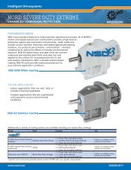
MODULAR SYSTEM<br />
TRANSMISSION TYPE ATTACHMENT ELEMENTS<br />
HELICAL FOOT MOUNT ELEKTIC MOTOR<br />
HELICAL FLANGE MOUNT<br />
SHAFT MOUNT REDUCER<br />
SHAFT MOUNT REDUCER<br />
WITH SOLID SHAFT<br />
WORM GEAR UNIT<br />
(FOOT MOUNT BASE)<br />
SHAFT MOUNT WORM GEAR UNIT<br />
BRAKING MOTOR<br />
FRICTION-WHEEL VARIABLE-<br />
SPEED GEAR MOTOR<br />
VARIABLE-SPEED GEAR<br />
MOTOR<br />
IEC ATTACHMENT CYLINDER<br />
FREE INPUT SHAFT HOUSING<br />
FLANGE MOUNT WORM GEAR UNIT DRIVE-END FLANGE<br />
HELICAL-BEVEL-GEAR UNIT CENTRIFUGAL CLUTCH/<br />
(FOOT MOUNT) COUPLING WITH OR<br />
WITHOUT BRAKE<br />
HELICAL-BEVEL-GEAR UNIT COMBINED COUPLING/<br />
SHAFT MOUNT CLUTCH AND BRAKE<br />
HELICAL-BEVEL-GEAR UNIT HELICAL SPEED REDUCER<br />
FLANGE MOUNT EXTREMLY LOW SPEEDS<br />
Getriebebau Nord<br />
Your Partner