OPERATING INSTRUCTIONS NORDAC Frequency Inverters
OPERATING INSTRUCTIONS NORDAC Frequency Inverters
OPERATING INSTRUCTIONS NORDAC Frequency Inverters

You also want an ePaper? Increase the reach of your titles
YUMPU automatically turns print PDFs into web optimized ePapers that Google loves.
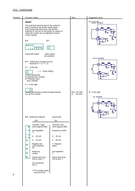
4.2.2 Control inputs<br />
Terminal Function / Notes Data Suggested circuit<br />
6<br />
General S1 to the left<br />
The push-lock terminal strip for the control inputs<br />
is located at the power supply board.<br />
If you remove the front cover, you will find<br />
switches S1 and S3 on this board, by means of<br />
which the inverter can be adjusted to various<br />
control signals.<br />
S 3 S 1<br />
8-pole DIP switch slider switch,<br />
two positions<br />
S 1 : Switchcover of signal level at<br />
terminals 6, 7, 8, 11, 12<br />
S 1 to the left<br />
Control commands<br />
a) potential free contacts<br />
b) Transistor (npn)<br />
open collector<br />
S 1 to the right<br />
----> works setting<br />
Control commands as external signal tension from +15 VDC S1 to the right<br />
e.g. as PLC-control to +30 VDC<br />
S 3 : Switchover setpoint actual point<br />
OFF ON<br />
Terminal 1 high- Terminal 1 lowohms<br />
against GND ohms against GND<br />
rpm-regulation <strong>Frequency</strong> control<br />
*)<br />
4 ... 20 mA 0 ... 20 mA<br />
0 ... 20 mA 4 ... 20 mA<br />
Negative set- +/- Setpoint<br />
point switched active<br />
off<br />
frequency rpm-regulation<br />
control *)<br />
Actual point area Actual point area<br />
30V to 100V *) 10V to 40V *)<br />
not connected<br />
(N.C.)<br />
*) PI controller option<br />
(see point 9.0)