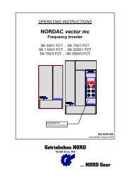
OPERATING INSTRUCTIONS NORDAC Frequency Inverters
OPERATING INSTRUCTIONS NORDAC Frequency Inverters
OPERATING INSTRUCTIONS NORDAC Frequency Inverters

You also want an ePaper? Increase the reach of your titles
YUMPU automatically turns print PDFs into web optimized ePapers that Google loves.
1.0 General<br />
<strong>NORDAC</strong> frequency <strong>Inverters</strong> are sine-related pulse-width modulated inverters with a constant DC link voltage.<br />
The inverters can be used for infinitely variable adjustment of the speeds of 3-phase motors with low loss.<br />
Use: - For single-motor and multiple-motor drives<br />
Output currents and DC link voltages are detected very - <strong>NORDAC</strong> frequency inverters are short-circuit proof,<br />
quickly and precisely. ground-fault resistant and stable at no load.<br />
The inverters permit 1.5 times the rated current for - There is no immediate switch-off in the event of overload 30<br />
seconds. of brief short-circuit<br />
The settings on the <strong>NORDAC</strong> <strong>Frequency</strong> Inverter are made with keys and displays in plain language (in dialogue with operater).<br />
Advantages: - Operating data in digital values<br />
- Precisely reproducible at any time and with any unit of the<br />
same series<br />
- Analogue adjustment facilities no longer present<br />
Separate braking chopper: - To be used for recovery of high regenerative braking energy<br />
to the DC link<br />
- To be connected to the + and - terminals (even afterwards)<br />
1.1 Delivery<br />
Examine the device immediately after delivery for transport damage such as distortions or loose parts.<br />
If damage has occured: - Contact the transport company without<br />
delay.<br />
- Make a careful note of damage.<br />
Important! this applies even if the packaging is undamaged.<br />
1.2 Scope of delivery<br />
Standard version : - IP 20 panel mounting unit<br />
with built-in line choke and output filter for<br />
compensating for line capacitances (see point 10.3)<br />
- Operating instructions<br />
- Output filters (see point 10.4)<br />
Accessoires available: - Braking chopper<br />
with integrated braking resistor (see point 7)<br />
- Additional choke for higher line capacitances<br />
(see point 10.3)<br />
- Special versions, e.g. for frequencies above 120 Hz<br />
1.3 Installation and operation<br />
Installation : - Installation by qualified personnel only<br />
- Observe local regulations applicable to installation of<br />
electrical systems<br />
- Adhere to accident prevention regulations<br />
- Take the usual safety measures<br />
Before switching on the unit: - Re-attach all covers and guards<br />
- Reconnect all plugs (---> push-locked terminal strips)<br />
- Also reconnect all plugs not being used<br />
CAUTION ! DANGER !<br />
=========================<br />
The power section can still be live up to 2 minutes after being disconnected from the mains.<br />
Inverter terminals, motor supply cables, and motor terminals can still be live.<br />
Touching exposed or unconnected terminals, cables, or parts of the device can lead to serious injuries or even death!<br />
Important Note ! Caution !<br />
==============================<br />
Motor stop owing to:<br />
- Electronic disable * Inverter terminals, motor leadwire, and motor<br />
- Terminal short-circuit terminals are still live !<br />
- Drive jammed * The motor may start up on its own if the inverter is not<br />
disconnected from the mains.<br />
The electronic disable facility is not a device as defined by German Accident Prevention Regulations (UVV).<br />
The terminals on the control board are not at mains potential.