OPERATING INSTRUCTIONS NORDAC Frequency Inverters
OPERATING INSTRUCTIONS NORDAC Frequency Inverters
OPERATING INSTRUCTIONS NORDAC Frequency Inverters

You also want an ePaper? Increase the reach of your titles
YUMPU automatically turns print PDFs into web optimized ePapers that Google loves.
Menu displayed text descritption<br />
option<br />
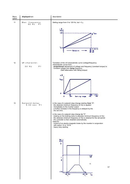
11 M a x . f r e q u e n c y Setting range from 0 to 120 Hz, but > fmin<br />
6 0 H z P 1<br />
12 U/f - c h a r a c t e r . Transition of the U/f characteristic curve (voltage/frequency<br />
characteristic curve) from<br />
5 0 H z P 1 - proportional adjustment of voltage and frequency (constant torque) to<br />
- constant voltage and rising frequency<br />
(field attenuation with falling torque)<br />
13 S e t p o i n t d e l a y In the case of a setpoint step-change starting from "0":<br />
0 . 0 0 s e c P 1 - the absolute minimum frequency (2 Hz) is applied<br />
immediately to the inverter output<br />
- a further increase in the frequency is delayed by the<br />
the set time<br />
In the case of a setpoint step-change to "0":<br />
- braking on the braking ramp to absolute minimum frequency (2 Hz)<br />
- the absolute minimum frequency (2 Hz) is retained for the set period<br />
- the controller is then disabled automatically<br />
Used for:<br />
- control of an electro-magnetic brake by the inverter in conjunction<br />
with option 14 or 15/16<br />
- heavy duty starting<br />
(s)<br />
17