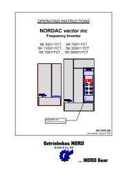
OPERATING INSTRUCTIONS NORDAC Frequency Inverters
OPERATING INSTRUCTIONS NORDAC Frequency Inverters
OPERATING INSTRUCTIONS NORDAC Frequency Inverters

Create successful ePaper yourself
Turn your PDF publications into a flip-book with our unique Google optimized e-Paper software.
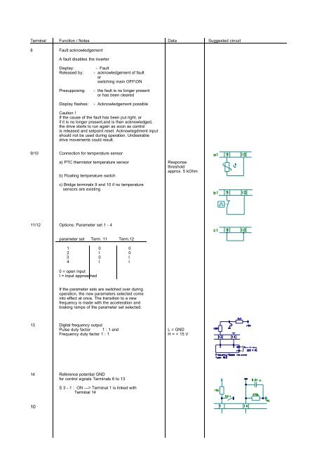
Terminal Function / Notes Data Suggested circuit<br />
8 Fault acknowledgement<br />
A fault disables the inverter<br />
Display: - Fault<br />
Released by: - acknowledgement of fault<br />
or<br />
switching main OFF\ON<br />
Presupposing: - the fault is no longer present<br />
or has been cleared<br />
Display flashes: - Acknowledgement possible<br />
Caution !<br />
If the cause of the fault has been put right, or<br />
if it is no longer present,and is then acknowledged,<br />
the drive starts to run again as soon as control<br />
is released and setpoint reset. Acknowlegdment input<br />
should not be used during operation. Undesirable<br />
drive movements could result.<br />
9/10 Connection for temperature sensor<br />
a) PTC thermistor temperature sensor Response<br />
threshold<br />
approx. 5 kOhm<br />
b) Floating temperature switch<br />
c) Bridge terminals 9 and 10 if no temperature<br />
sensors are existing<br />
11/12 Options: Parameter set 1 - 4<br />
parameter set Term. 11 Term.12<br />
1 0 0<br />
2 I 0<br />
3 0 I<br />
4 I I<br />
0 = open input<br />
I = input approached<br />
If the parameter sets are switched over during<br />
operation, the new parameters selected come<br />
into effect at once. The transition to a new<br />
frequency is made with the acceleration and<br />
braking ramps of the parameter set selected.<br />
13 Digital frequency output<br />
Pulse duty factor 1 : 1 and L = GND<br />
<strong>Frequency</strong> duty factor 1 : 1 H = + 15 V<br />
14 Reference potential GND<br />
for control signals Terminals 6 to 13<br />
10<br />
S 3 - 1 : ON ---> Terminal 1 is linked with<br />
Terminal 14