OPERATING INSTRUCTIONS NORDAC Frequency Inverters
OPERATING INSTRUCTIONS NORDAC Frequency Inverters
OPERATING INSTRUCTIONS NORDAC Frequency Inverters

Create successful ePaper yourself
Turn your PDF publications into a flip-book with our unique Google optimized e-Paper software.
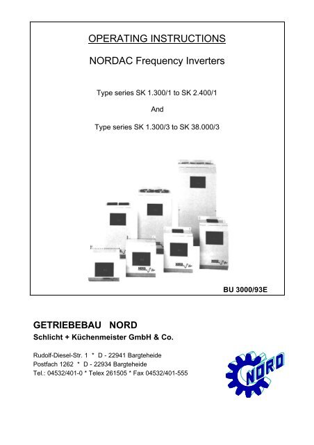
GETRIEBEBAU NORD<br />
<strong>OPERATING</strong> <strong>INSTRUCTIONS</strong><br />
<strong>NORDAC</strong> <strong>Frequency</strong> <strong>Inverters</strong><br />
Type series SK 1.300/1 to SK 2.400/1<br />
And<br />
Type series SK 1.300/3 to SK 38.000/3<br />
Schlicht + Küchenmeister GmbH & Co.<br />
Rudolf-Diesel-Str. 1 * D - 22941 Bargteheide<br />
Postfach 1262 * D - 22934 Bargteheide<br />
Tel.: 04532/401-0 * Telex 261505 * Fax 04532/401-555<br />
BU 3000/93E
Table of contents<br />
Page<br />
1.0 General 1<br />
1.1 Delivery 1<br />
1.2 Scope of delivery 1<br />
1.3 Installation and operation 1<br />
2.0 Installation 2<br />
3.0 <strong>Frequency</strong> inverter dimensions 3<br />
3.1 Braking chopper dimensions 3<br />
4.0 Connection 4<br />
4.1 Power section 4<br />
4.1.1 Type SK 1.300/1 - SK 2.400/1 4<br />
4.1.2 Type SK 1.300/3 - SK 38.000/3 4<br />
4.1.3 Additional measures 4<br />
4.2 Control section 5<br />
4.2.1 Control terminal strip 5<br />
4.2.2 Control inputs 6<br />
5.0 Operation and displays 12<br />
5.1 Setting and display facilities 13<br />
5.2 Description of settings and displays 14<br />
6.0 Commssioning 22<br />
6.1 Parameter record 23<br />
7.0 Braking chopper 24<br />
7.1 Technical data 24<br />
7.2 Installation instructions 24<br />
7.3 Settings 24<br />
7.4 Selection criteria 24<br />
8.0 Failure and faults 26<br />
9.0 Speed controller 27<br />
10.0 Mains filter 29<br />
10.1 Radio interference suppression 29<br />
10.2 Effect on other consumers 30<br />
10.3 Line capacitances (motor cable) 30<br />
10.4 Output filters 30<br />
10.5 Regulations 30<br />
11.0 Technical data 31<br />
T.-Nr.: 06063082<br />
Stand: 42/93
1.0 General<br />
<strong>NORDAC</strong> frequency <strong>Inverters</strong> are sine-related pulse-width modulated inverters with a constant DC link voltage.<br />
The inverters can be used for infinitely variable adjustment of the speeds of 3-phase motors with low loss.<br />
Use: - For single-motor and multiple-motor drives<br />
Output currents and DC link voltages are detected very - <strong>NORDAC</strong> frequency inverters are short-circuit proof,<br />
quickly and precisely. ground-fault resistant and stable at no load.<br />
The inverters permit 1.5 times the rated current for - There is no immediate switch-off in the event of overload 30<br />
seconds. of brief short-circuit<br />
The settings on the <strong>NORDAC</strong> <strong>Frequency</strong> Inverter are made with keys and displays in plain language (in dialogue with operater).<br />
Advantages: - Operating data in digital values<br />
- Precisely reproducible at any time and with any unit of the<br />
same series<br />
- Analogue adjustment facilities no longer present<br />
Separate braking chopper: - To be used for recovery of high regenerative braking energy<br />
to the DC link<br />
- To be connected to the + and - terminals (even afterwards)<br />
1.1 Delivery<br />
Examine the device immediately after delivery for transport damage such as distortions or loose parts.<br />
If damage has occured: - Contact the transport company without<br />
delay.<br />
- Make a careful note of damage.<br />
Important! this applies even if the packaging is undamaged.<br />
1.2 Scope of delivery<br />
Standard version : - IP 20 panel mounting unit<br />
with built-in line choke and output filter for<br />
compensating for line capacitances (see point 10.3)<br />
- Operating instructions<br />
- Output filters (see point 10.4)<br />
Accessoires available: - Braking chopper<br />
with integrated braking resistor (see point 7)<br />
- Additional choke for higher line capacitances<br />
(see point 10.3)<br />
- Special versions, e.g. for frequencies above 120 Hz<br />
1.3 Installation and operation<br />
Installation : - Installation by qualified personnel only<br />
- Observe local regulations applicable to installation of<br />
electrical systems<br />
- Adhere to accident prevention regulations<br />
- Take the usual safety measures<br />
Before switching on the unit: - Re-attach all covers and guards<br />
- Reconnect all plugs (---> push-locked terminal strips)<br />
- Also reconnect all plugs not being used<br />
CAUTION ! DANGER !<br />
=========================<br />
The power section can still be live up to 2 minutes after being disconnected from the mains.<br />
Inverter terminals, motor supply cables, and motor terminals can still be live.<br />
Touching exposed or unconnected terminals, cables, or parts of the device can lead to serious injuries or even death!<br />
Important Note ! Caution !<br />
==============================<br />
Motor stop owing to:<br />
- Electronic disable * Inverter terminals, motor leadwire, and motor<br />
- Terminal short-circuit terminals are still live !<br />
- Drive jammed * The motor may start up on its own if the inverter is not<br />
disconnected from the mains.<br />
The electronic disable facility is not a device as defined by German Accident Prevention Regulations (UVV).<br />
The terminals on the control board are not at mains potential.
2.0 Installation<br />
The units require adequate ventilation. Minimum clearances between the individual units must be observed for this purpose.<br />
The heated air is to be carried off above the devices!<br />
Front view Side view<br />
If the mountig surface does not form a rear surface --> fit a baseplate<br />
Type a b c d<br />
SK 1.300/.; SK 1.900/. 10 10 100 50<br />
SK 2.400/1 ; SK 3.600/3; SK 5.900/3 10 10 100 50<br />
SK 7.500/3; SK 10.000/3; SK 15.000/3 10 10 100 50 All dimensions in mm<br />
SK 20.000/3 10 10 150 80<br />
SK 30.000/3; SK 38.000/3 10 10 200 100<br />
Several devices one above another --> Take precautions against heat build-up (e.g. air baffles)<br />
2<br />
not allowed
3.0 <strong>Frequency</strong> inverter dimensions<br />
Version shown: IP 20<br />
SK 1.300 ... SK 15.000/3 SK 20.000/3 ... 38.000/3<br />
Detail:<br />
Fixing hole<br />
Type T B L a b c e e1 e2 f f1<br />
SK 1.300/1 185 203 205 180 182 10 5,2<br />
SK 1.900/1 185 203 250 180 227 10 5,2<br />
SK 2.400/1 185 203 290 180 265 10 5,2<br />
SK 1.300/3 185 203 205 180 182 10 5,2<br />
SK 1.900/3 185 203 250 180 227 10 5,2<br />
SK 3.600/3 185 203 290 180 265 10 5,2<br />
SK 5.900/3 185 203 355 180 326 12 6,2<br />
SK 7.500/3 + SK 10.000/3 185 203 430 180 401 12 6,2<br />
SK 15.000/3 250 268 520 235 484 14 6,2<br />
SK 20.000/3 250 319 642 600 20 22 299 540 280 12 6,2<br />
SK 30.000/3 292 353 728 680 25 20 333 620 320 12 6,2<br />
SK 38.000/3 252 440 647 595 25 73 420 472 236 12 6,2<br />
3.1 Braking chopper dimensions<br />
All dimensions in mm<br />
All dimensions in mm<br />
Type T B L e e1 f<br />
SK 3/350/32 175 100 85 90 64 5,5<br />
SK 6/350/64 175 100 85 90 64 5,5<br />
SK 3/600/64 175 100 85 90 64 5,5<br />
SK 6/600/180 185 222 110 200 100 5,5<br />
SK 12/600/360 185 222 110 200 100 5,5<br />
SK 24/600/720 185 222 170 200 160 5,5<br />
SK 40/600 150 150 195 128 175 6,5<br />
SK 80/600 150 150 195 128 175 6,5<br />
SK 130/600 150 150 195 128 175 6,5<br />
3
4.0 Connection<br />
4.1 Power section<br />
4.1.1 Typ SK 1.300/1 - SK 2.400/1<br />
Connection for mains, braking chopper and motor - via screw-type push-lock terminal strips on the lower output stage<br />
board<br />
Maximum line cross-sectional area - 2,5 mm 2<br />
Keep earth connection (PE) at very low ohms.<br />
<strong>NORDAC</strong> SK 1.300/1...SK 2.400/1 - Please mind the line lengths!<br />
Mains Braking chopper Motor<br />
SK 3/350/22 +<br />
SK 6/350/64<br />
4.1.2 Typ SK 1.300/3 - SK 38.000/3<br />
* if required<br />
- Cf. point 10.3<br />
Connection for mains, braking chopper and motor SK 1300/3 to SK 5900/3<br />
Maximum line cross-sectional area - 2,5 mm 2 via screw-type push-lock terminal strip on the<br />
Keep earth connection (PE) at very low ohms lower output stage board<br />
SK 7.500/3 and 10.000/3<br />
<strong>NORDAC</strong> SK 1.300/3...SK 38.000/3 - 4,0 mm 2 via screw-type terminal strip on the line and output choke<br />
Mains Braking chopper Motor<br />
SK 3/600/64...<br />
SK 24/600/720<br />
SK 40/600 ... SK 130/600<br />
(-) (+) (PE)<br />
SK 15.000/3 to SK 30.000/3<br />
- 10 mm 2 via screw-type terminal strip on the line and output choke<br />
SK 38.000/3<br />
- 16 mm 2 via screw-type terminal strip on the line and output choke<br />
* if required - Please mind the line lengths!<br />
- Cf. point 10.3<br />
braking resistance<br />
4.1.3 Additional measures (compare point 10.2, 10.3 and 10.4)<br />
Types SK 1.300/1 to SK 2.400/1 and SK 1.300/3 to SK 38.000/3<br />
4<br />
Also for braking chopper connection (recommended < 10m)<br />
230 / 240 V<br />
50 / 60 Hz<br />
auxiliary voltage
4.2 Control section<br />
Connection for the control lines - 22-pole control terminal strip on the mains power supply board,<br />
subdivided into three blocks<br />
Maximum connection cross sectional - 1,5 mm 2<br />
area<br />
4.2.1 Control terminal strip Setpoint - shield lines.<br />
(short lines twisted at least)<br />
Reference potential for the setpoints (GND)<br />
Setpoint - 10 V / 0 / + 10 V DC<br />
Setpoint - 10 V / 0 / + 10 V DC<br />
Setpoint 0 (4) ... 20 mA<br />
+ 10 V reference voltage<br />
Reversing<br />
Electronic release<br />
Fault acknowledgement<br />
PTC thermistor/tempearture sensor<br />
PTC thermistor/temperature sensor<br />
Parameter switchover input 1<br />
Parameter switchover input 2<br />
Digital frequency output<br />
Reference potential for the control inputs<br />
(GND)<br />
Tachogenerator + *)<br />
Tachogenerator - *)<br />
max.load rating 240 V ~ / 60 V = ; 0,8 A Multifunction relay<br />
max.load rating 240 V ~ / 60 V = ; 0,8 A <strong>Frequency</strong> signalling relay<br />
max.load rating 240 V ~ / 60 V = ; 0,8 A Fault signalling relay<br />
*) Option<br />
5
4.2.2 Control inputs<br />
Terminal Function / Notes Data Suggested circuit<br />
6<br />
General S1 to the left<br />
The push-lock terminal strip for the control inputs<br />
is located at the power supply board.<br />
If you remove the front cover, you will find<br />
switches S1 and S3 on this board, by means of<br />
which the inverter can be adjusted to various<br />
control signals.<br />
S 3 S 1<br />
8-pole DIP switch slider switch,<br />
two positions<br />
S 1 : Switchcover of signal level at<br />
terminals 6, 7, 8, 11, 12<br />
S 1 to the left<br />
Control commands<br />
a) potential free contacts<br />
b) Transistor (npn)<br />
open collector<br />
S 1 to the right<br />
----> works setting<br />
Control commands as external signal tension from +15 VDC S1 to the right<br />
e.g. as PLC-control to +30 VDC<br />
S 3 : Switchover setpoint actual point<br />
OFF ON<br />
Terminal 1 high- Terminal 1 lowohms<br />
against GND ohms against GND<br />
rpm-regulation <strong>Frequency</strong> control<br />
*)<br />
4 ... 20 mA 0 ... 20 mA<br />
0 ... 20 mA 4 ... 20 mA<br />
Negative set- +/- Setpoint<br />
point switched active<br />
off<br />
frequency rpm-regulation<br />
control *)<br />
Actual point area Actual point area<br />
30V to 100V *) 10V to 40V *)<br />
not connected<br />
(N.C.)<br />
*) PI controller option<br />
(see point 9.0)
Terminal Function / Notes Data Suggested circuit<br />
1 S 3 - 1 : ON<br />
- Terminal 1 is linked to Terminal 14 (GND):<br />
Setpoints at Terminal 2 and Terminal 3 are<br />
added together<br />
S 3 - 1 : OFF<br />
- Terminal 1 is at high ohms against GND approx.130 kOhm<br />
- Inputs Terminal 1 and Terminal 2 or<br />
Terminal 1 and Terminal 3 are working<br />
as differential inputs. The differential<br />
inputs cannot both be used at the same<br />
time as linear addition of their setpoints<br />
would then not be possible.<br />
The differential amplifier is ineffective<br />
if Terminal 14 and Terminal 1 are both given<br />
the same potential by the external control<br />
unit, e.g. protection lead (PE) or ext. GND<br />
2 or 3 Setpoints must be free of interference. Input resistance<br />
Check with oscilloscope if necessary approx 130 kOhm<br />
acceptable: not acceptable:<br />
If necessary, lay the setpoint-lines as shielded<br />
wiring. The shield must be connected on one side<br />
to GND or PE.<br />
The setpoint-lines should be twisted if they are<br />
short and not shielded.<br />
S 3 - 5 : ON -10V ... 0 ...+10V<br />
with direction recognition from the polarity of the<br />
setpoint.<br />
The direction of rotation at Terminal 6 then must not<br />
be approached.<br />
Setpoint Terminal 6 Direction<br />
0 ... + 10V 0 clockwise<br />
0 ... + 10V I counter-clockwise<br />
0 ... - 10V 0 counter-clockwise<br />
0 ... - 10V I counter-clockwise<br />
0 = not approached<br />
I = approached<br />
S 3 - 5 : OFF<br />
Direction change only possible by signal 0 ... + 10V<br />
to Terminal 6<br />
Setpoint Terminal 6 Direction<br />
0 ... + 10 0 clockwise<br />
0 ... + 10 I counter-clockwise<br />
0 ... - 10 0 counter-clockwise,<br />
with the minimum<br />
frequency set<br />
0 ... - 10 I counter-clockwise,<br />
with the minimum<br />
frequency set<br />
Aim: No unitentional reversal will occur at<br />
setpoints with negative upper waves,<br />
alternatively selection of direction at<br />
Terminal 6 will not be obstructed. 7
Terminal Function / Notes Data Suggested circuit<br />
2 or 3 a) Setpoint setting<br />
with potentiometer<br />
without direction recognition Poti<br />
S 3 - 1 : ON or OFF min. 1 kOhm<br />
S 3 - 5 : OFF max. 20 kOhm<br />
b) as for a), but<br />
with start/stop by contact-setting<br />
Contact open: Setpoint = 0 = fmin.<br />
Contact closed: Set setpoint<br />
equal to/less than fmax.<br />
c) Setpoint with fixed internal setting<br />
without direction recognition<br />
S 3 - 1 : ON or OFF<br />
S 3 - 5 : OFF<br />
Contact from 2(3) to 1: Setpoint = 0 = fmin.<br />
Contact from 2(3) to 5: Setpoint = 10V = fmax.<br />
Note: further setpoints fmin. and fmax.<br />
can also be programmed into the<br />
parameter sets 1 to 4 (Point 11/12)<br />
d) Setpoint setting by an external voltage source<br />
without direction recognition 0 ... +10V<br />
S 3 - 1: ON or OFF<br />
S 3 - 5: OFF<br />
e) as for d), but<br />
with direction recognition -10V...0...+10V<br />
S 3 - 1 : ON or OFF<br />
S 3 - 5 : ON<br />
f) as for d) or e) but unity<br />
control-factor setting at 5 V 0 ... +5V<br />
S 3 - 1 : ON -5 ... 0 ... +5V<br />
S 3 - 5 : OFF or ON<br />
g) Several setpoints via potentiometers Poti:<br />
without direction recognition min. 2 kOhm<br />
S 3 - 1 : ON max. 20 kOhm<br />
S 3 - 5 : OFF<br />
K 1 K 2 Setpoint<br />
open open 0 = fmin.<br />
closed open Setpoint 1<br />
open closed Setpoint 2<br />
closed closed Sum of internal limit:<br />
Setpoint 1 approx 11 V<br />
and<br />
Setpoint 2<br />
h) Setpoint setting via potentiometers with direction<br />
recognition (external voltage source needed)<br />
S 3 - 1 : ON or OFF<br />
S 3 - 5 : ON<br />
4 Setpoint from marked current 0(4) ... 20 mA<br />
S 3 - 1 : ON Load: 250 Ohm<br />
0 ... 20 mA : S 3 - 3 ON<br />
S 3 - 4 OFF<br />
4 ... 20 mA : S 3 - 3 OFF<br />
S 3 - 4 ON<br />
5 Reference voltage for setpoint supply +10V, +/- 1 %<br />
max. 12 mA<br />
(short-circuit proof)<br />
8
Terminal Function / Notes Data Suggested circuit<br />
Terminals 6-14 generally<br />
The control signals at Terminals 6, 7, 8, 11<br />
and 12 relate to the reference potential GND<br />
at Terminal 14.<br />
Switch S1 to the left<br />
a) Contacts potential free<br />
or<br />
b) Transistors with<br />
open collector<br />
If switch S1 is set to the right<br />
a) outside voltage +15 ... + 30V<br />
Note:<br />
Control commands can be switched to several inputs<br />
at the same time, e.g. direction and parameter<br />
switchover, with one command or output<br />
a) Contact potential free<br />
b) Voltage signal from PLC if the loading is<br />
permissible (see general points on control<br />
terminal strip)<br />
6 Reversing via control command<br />
S 3 - 5 : OFF or ON Setpoint:<br />
0 ... + 10V<br />
The inverter brakes with the braking ramp, or<br />
changes the field rotation direction, and 0(4) ... 20 mA<br />
accelerates to the high-speed ramp<br />
(see ramp diagramm)<br />
7 Electronic Release<br />
Parameter "rampdown" (menue point 20) is programmed<br />
at "on" and electronic is disabled:<br />
- the motor is run down to braking ramp<br />
- all other functions will be finished as set<br />
(e.g. setpoint delay and DC braking)<br />
- finally electronic release will lock output<br />
automatically<br />
Aim:<br />
A completely closed working cycle can only be<br />
controlled with the following switches set:<br />
- setpoint (Terminal 2 or 3, function c)<br />
- direction recognition (Terminal 6)<br />
- electronic release (Terminal 7)<br />
t<br />
If an electromecanical brake is existing:<br />
- control of external brake relay with help of<br />
frequency signalling relay (terminal 19/20)<br />
fset=2,0 Hz and setpoint delay<br />
t = 0,02 - 0,3 s acc. to reaction time of the brake.<br />
Caution ! Danger !<br />
Even though ELECTRONIC RELEASE is locked and<br />
motor is de-energized, the motor is not electrically<br />
insulated from the mains. Working on<br />
the inverter power terminals, motor leadwire, or<br />
motor terminals is very dangerous ! Take care!<br />
9
Terminal Function / Notes Data Suggested circuit<br />
8 Fault acknowledgement<br />
A fault disables the inverter<br />
Display: - Fault<br />
Released by: - acknowledgement of fault<br />
or<br />
switching main OFF\ON<br />
Presupposing: - the fault is no longer present<br />
or has been cleared<br />
Display flashes: - Acknowledgement possible<br />
Caution !<br />
If the cause of the fault has been put right, or<br />
if it is no longer present,and is then acknowledged,<br />
the drive starts to run again as soon as control<br />
is released and setpoint reset. Acknowlegdment input<br />
should not be used during operation. Undesirable<br />
drive movements could result.<br />
9/10 Connection for temperature sensor<br />
a) PTC thermistor temperature sensor Response<br />
threshold<br />
approx. 5 kOhm<br />
b) Floating temperature switch<br />
c) Bridge terminals 9 and 10 if no temperature<br />
sensors are existing<br />
11/12 Options: Parameter set 1 - 4<br />
parameter set Term. 11 Term.12<br />
1 0 0<br />
2 I 0<br />
3 0 I<br />
4 I I<br />
0 = open input<br />
I = input approached<br />
If the parameter sets are switched over during<br />
operation, the new parameters selected come<br />
into effect at once. The transition to a new<br />
frequency is made with the acceleration and<br />
braking ramps of the parameter set selected.<br />
13 Digital frequency output<br />
Pulse duty factor 1 : 1 and L = GND<br />
<strong>Frequency</strong> duty factor 1 : 1 H = + 15 V<br />
14 Reference potential GND<br />
for control signals Terminals 6 to 13<br />
10<br />
S 3 - 1 : ON ---> Terminal 1 is linked with<br />
Terminal 14
Terminal Function / Notes Data Suggested circuit<br />
15/16 Terminals for tachogenerator<br />
(speed controller option)<br />
15 Connection of the positive voltage of<br />
the tachogenrator<br />
The polarity at the terminals must remain<br />
the same in the case of reversing the motor<br />
DIP switch at the power supply board:<br />
frequency- Speedcontrolled<br />
controlled<br />
S 3 - 1 ON (OFF) ON<br />
S 3 - 2 ON OFF<br />
S 3 - 6 OFF ON<br />
highest control point<br />
10-40V 30-100V<br />
S 3 - 7 ON OFF<br />
Only terminal 2 can be used as input for a<br />
speed setpoint.<br />
a) DC-tachogenerator one direction<br />
b) DC-tachogenerator both directions<br />
c) AC-tachogenerator with bridge-rectifier<br />
for both directions<br />
17/18 Multifunction relay<br />
Closing of the floating contact with<br />
a) programmed at "Current" I > ISet<br />
b) programmed at "<strong>Frequency</strong>" f > fSet<br />
19/20 <strong>Frequency</strong>-signalling relay<br />
Closing of the floating contact with<br />
f > fSet<br />
21/22 Fault-signalling relay<br />
Floating contact open:<br />
- Fault has occured<br />
- The inverter is disconnected from the mains<br />
Contact is shown in no-voltage<br />
condition. When the inverter is<br />
ready for operation, the contact<br />
is closed.<br />
11
5.0 Operation and displays<br />
General<br />
On the control board you will find: - the two-line alpanumerical liquid-cystral display with 16 digits each<br />
- 5 keys for entering all operating data (parameters)<br />
PARAMETER keys<br />
PARAMETER- VALUE- ENTERkeys<br />
keys keys<br />
Paging for- Change Enter<br />
wards/back- values changed<br />
wards in lower / values<br />
program higher<br />
off / on<br />
Example:<br />
Display during operation<br />
- Parameter 2 selected (P2)<br />
- Rotation clockwise (R)<br />
- <strong>Frequency</strong> (F) 86,7 Hz<br />
- Voltage (U) 230 V<br />
- Current (I) 0,7 A<br />
Paging through the program (menu)<br />
- Possible in enable and<br />
disable status<br />
- Repeated use of one key - continuous paging in program<br />
- Simultaneous use of both<br />
keys - program jumps back to start<br />
Program start and<br />
disabled state - device type is displayed<br />
e.g.<br />
N O R D A C<br />
S K 5 . 9 0 0 / 3<br />
Program start and<br />
enabled state - The operating data (status displays) are displayed<br />
e.g.<br />
P 1 F / Hz U / V I / A<br />
R 0 . 0 0 0 . 0<br />
VALUE keys - changing the parameters<br />
- selecting the languages<br />
- switching the functions "ON/OFF"<br />
Keeping the keys pressed makes the values change faster, thus speeding up setting work.<br />
A change is only possible: - in disabled condition<br />
- if the frequency lies below the absolute minimum frequency<br />
ENTER key<br />
Press the ENTER key in order to accept a newly set value.<br />
If the unit flashes or shows *, this indicates an altered value which has not yet been accepted/acknowledged.<br />
If you do not acknowledge after the change, the set value is deleted immediately if you press a program key or the<br />
electronic-disable. The previously stored value is retained.<br />
LCD-Display<br />
Display of the operating data (parameters) - in plain text<br />
- with the current value<br />
- with the unit<br />
12
5.1 Settings and displays possible<br />
Menu displayed text/ Range Increment<br />
option works setting min /max value<br />
1 <strong>NORDAC</strong> SK 1.300/1 to Corresponding to the actual type<br />
SK....../. SK 38.000/3<br />
2 Language:<br />
German German / English<br />
3 Parameter set<br />
1 1 / 4 1<br />
4 Copy parameter<br />
from 2 * 1 / 4 1<br />
5 Accelerat. time 0,05 s in the range from 0,05 to 5 seconds<br />
5.00 sec P1 0,05 / 120 sec 0,1 s in the range from 5 to 10 seconds<br />
0,5 s in the range from 10 to 120 seconds<br />
6 Decelerat. time 0,05 s in the range from 0,05 to 5 seconds<br />
5.00 sec P1 0,05 / 120 sec 0,1 s in the range from 5 to 10 seconds<br />
0,5 s in the range from 10 to 120 seconds<br />
7 Static boost<br />
8 % P1 0 / 30 % 1 %<br />
7.1 Start val. U contr.<br />
8 % P1 0 / 30 % 1 %<br />
8 Dynamic boost<br />
0 % P1 0 / 30 % 1 %<br />
8.1 Limit U control<br />
0 % P1 0 / 30 % 1 %<br />
9 Time dynam. boost<br />
0.0 sec P1 0 / 10 sec. 0,1 s<br />
10 Min. frequency fmin < fmax<br />
0,0 Hz P1 0 / 120 Hz 0,1 Hz<br />
11 Max. frequency fmax > fmin<br />
100,0 Hz P1 0 / 120 Hz 0,1 Hz<br />
>120 Hz if required<br />
12 U/f-character.<br />
50 Hz P1 30 / 999 Hz 1 Hz<br />
13 Setpoint delay<br />
0.00 sec P1 0 / 10 sec. 0,01 s<br />
14 <strong>Frequency</strong> relay<br />
50.5 Hz P1 0 / 120 Hz 0,1 Hz<br />
15 Multifunct. relay<br />
Current P1 Current/<strong>Frequency</strong><br />
16 Funct. frequency<br />
2.0 Hz P1 0 / 120 Hz 0,1 Hz<br />
17 Function current<br />
... A P1 0 / 100 A 0,1 A<br />
18 Sensitivity<br />
15 % P1 5 / 50 % 1 %<br />
19 Ramp respon. time<br />
On P1 On / Off<br />
20 Ramp down<br />
Off P1 On / Off<br />
21 DC braking<br />
Off P1 On / Off<br />
22 Volt. DC braking<br />
0 % P1 0 / 30 % 1 %<br />
23 Time DC braking<br />
0.0 sec P1 0 / 10 sec. 0,1 s<br />
24 Contr. reac. curr.<br />
Off On / Off<br />
25 Refer. reac. curr.<br />
1,0 A P1 0 / 99,9 A 0,1 A<br />
26 Fault history 1 last 5 error<br />
Excess temp.motor 2 messages<br />
27 Actual fault up to 20 different<br />
No fault 0 errors<br />
28 cosphi Iw/A Ib/A displayed operating value<br />
1,0 0,0 0,0 (status indicator)<br />
29 F/Hz P/kW cos displayed operating value<br />
0,0 0,0 1,0 (status indicator) 13
5.2 Description of settings and displays<br />
Menu displayed text Description<br />
option<br />
1 N O R D A C Circuitry disabled<br />
S K . . . . . . / . - Paging in program possible<br />
- Changing values possible<br />
P 1 F / H z U / V I / A Circuitry enabled<br />
R 0.0 0.0 0.0 - Paging in program possible<br />
2 L a n g u a g e : Selecting the language ---> VALUE keys<br />
G e r m a n Acknowledging ---> ENTER keys<br />
3 P a r a m e t e r s e t Up to four different complete parameter sets can be programmed. The<br />
1 parameters of the parameter set selected are shown in the display<br />
regardless of the settings at Terminals 11 and 12.<br />
The exception is the operation/status indicator (option 1). This<br />
shows the operating values of the parameter set at Terminals 11 and<br />
12.<br />
VALUE keys - select the parameter sets 1 to 4 be programmed<br />
ENTER keys - acknowledge<br />
4 C o p y p a r a m e t e r Copying the parameter sets:<br />
f r o m 2 * PROGRAM keys ---> back to option 3<br />
VALUE keys ---> setting the number of the parameter set to which<br />
the required parameter set is to be copied<br />
ENTER keys ---> acknowledge<br />
PROGRAM keys ---> select option 4<br />
VALUE keys ---> select number of parameter set to be copied<br />
ENTER key ---> display shows "Wait"<br />
Copying is completed in a few seconds.<br />
Display "Wait" is cleared.<br />
The parameters of the parameter set selected with option 4 are now also in<br />
the parameter set which was selected with option 3.<br />
Only deviating values now need to be set in it.<br />
5 A c c e l e r a t . t i m e Setting range: from 0.05 to 120 Sekunden --->VALUE<br />
keys<br />
5 . 0 0 s e c P 1 The time refers to the set max. frequency.<br />
Changing the max. frequency with the same acceleration time affects:<br />
---> acceleration<br />
---> required power<br />
Caution: Too short an acceleration time will cause instability of the<br />
motor (see option 19)<br />
Precautions:<br />
---> lengthen the acceleration time<br />
14<br />
example: fmax 1 or fmax 2
5.2 Description of settings and displays<br />
Menu displayed text description<br />
option<br />
6 D e c e l e r a t . t i m e Setting range: from 0.05 to 120 seconds ---> VALUE keys<br />
5 . 0 0 s e c P 1 The time refers to the set max. frequency.<br />
Changing the max. frequency with the same braking time affects:<br />
---> deceleration<br />
---> required power<br />
---> energy fed back<br />
Caution: Too short a deceleration time will cause instability of the<br />
motor (see option 19)<br />
Energy fed back results in:<br />
---> a rise in the DC link voltage<br />
---> inverter switching off (message: overvoltage)<br />
Precautions:<br />
---> use a braking chopper<br />
---> lengthen the acceleration time<br />
7 S t a t i c b o o s t Setting the initial voltage from 0-30 % of the rated voltage --> VALUE keys<br />
8 % P 1 Aim: - starting the motor against maximum load<br />
---> select a low frequency (2 - 5 Hz)<br />
---> check the starting current with the help of display<br />
(option 1)<br />
---> if the current is low (motor will not start)<br />
- intensify boost<br />
---> if the current is too high (motor is jerking)<br />
decrease boost<br />
7.1 S t a r t v a l . U c o n t r . Initial voltage at "Contr.reac.curr." "On" (option 24)<br />
8 % P 1 From 0 to 30 % of nominal voltage ---> VALUE keys<br />
The regulator adds a variable voltage depending on<br />
load to this initial voltage.<br />
Aim: - Without a regulated time delay an adjustable<br />
minimum start-up torque is immediately avialable.<br />
Setting:<br />
---> regulation of "Contr.reac.curr." to pos. "Off" (option 24)<br />
---> setting "Static boost" as described in option 7 but for minimum torque<br />
needed only<br />
---> regulation of "Contr.reac.curr." to pos. "On" (option 24)<br />
15
Menu displayed text Description<br />
option<br />
16<br />
8 D y n a m i c b o o s t Adding a time-limited "dynamic" starting torque with Contr. reac. curr.<br />
0 % P1 regulator set at "Off" (option 24):<br />
0 - 30 % of the rated voltage ---> VALUE keys<br />
Aim: - reducing the thermal load on the motor<br />
- lifting brake of sliding-rotor motors<br />
---> set time (option 9)<br />
---> boost drops to value set under option 7 (static boost)<br />
within time set under option 9<br />
---> check the starting current - see option 7 (the time can be<br />
prolonged for this purpose --> simplified read-off)<br />
8.1 L i m i t U c o n t r o l With "Contr. reac. curr." "On" (option 24), setting of the maximum voltage<br />
0 % P 1 which the controller is able to add to the voltage resulting from U/f characteristic<br />
curve. From 0 to 30% of the rated voltage ---> VALUE keys<br />
Aim: - preventing over-saturation on the motor through excessively high<br />
correction values<br />
Setting:<br />
---> "Contr. reac. curr." "Off" (option 24)<br />
---> "Static boost" setting as described under option 7 until required<br />
start-up current/torque is reached<br />
---> "Contr. reac. curr." "On" (option 24)<br />
---> enter value obtained at option 8.1 "Limit U control"<br />
---> correct "Start val. U contr." option 7.1 and enter value<br />
previously obtained<br />
9 T i m e d y n a m . b o o s t Used to limit duration of dynamic boost<br />
0 . 0 s e c P 1 Aim: - avoiding additional heating of the motor at low frequencies<br />
10 M i n . f r e q u e n c y Setting range from 0 to < fmax<br />
0 H z P 1
Menu displayed text descritption<br />
option<br />
11 M a x . f r e q u e n c y Setting range from 0 to 120 Hz, but > fmin<br />
6 0 H z P 1<br />
12 U/f - c h a r a c t e r . Transition of the U/f characteristic curve (voltage/frequency<br />
characteristic curve) from<br />
5 0 H z P 1 - proportional adjustment of voltage and frequency (constant torque) to<br />
- constant voltage and rising frequency<br />
(field attenuation with falling torque)<br />
13 S e t p o i n t d e l a y In the case of a setpoint step-change starting from "0":<br />
0 . 0 0 s e c P 1 - the absolute minimum frequency (2 Hz) is applied<br />
immediately to the inverter output<br />
- a further increase in the frequency is delayed by the<br />
the set time<br />
In the case of a setpoint step-change to "0":<br />
- braking on the braking ramp to absolute minimum frequency (2 Hz)<br />
- the absolute minimum frequency (2 Hz) is retained for the set period<br />
- the controller is then disabled automatically<br />
Used for:<br />
- control of an electro-magnetic brake by the inverter in conjunction<br />
with option 14 or 15/16<br />
- heavy duty starting<br />
(s)<br />
17
Menu displayed text description<br />
option<br />
18<br />
14 F r e q u e n c y r e l a y Floating contact at Terminals 19/20<br />
5 0 . 5 H z P 1 - closes ---> output frequency exceeds the set value<br />
- opens ---> output frequency drops below the set value<br />
VALUE keys ---> set frequency required<br />
15 M u l t i f u n c t . r e l a y VALUE keys ---> function frequency - signals a further frequency, chosen<br />
c u r r e n t P 1 ---> function current - signals a variable current, set<br />
16 F u n c t . f r e q u e n c y With function selected ---> frequency<br />
2 . 0 H z P 1 - as described under option 14<br />
- but signalling at Terminals 17/18<br />
- contact closes if the set frequency is exceeded<br />
17 F u n c t i o n c u r r e n t With function selected ---> current<br />
. . . A P 1 Floating contact at terminals 17/18<br />
- closes ---> output current exceeds the set value<br />
- opens ---> output current drops below the set value minus the<br />
value set with the sensitivity (option 18)<br />
18 S e n s i t i v i t y Function: setting a switch-off threshold<br />
1 5 % P 1<br />
Aim: avoids persistent switching of the multifunction relay<br />
in the "current" function on slight current fluctuations
Menu displayed text Description<br />
option<br />
19 R a m p r e s p o n . t i m e Ramp response time programmed "On":<br />
O n P 1 - interruption in further frequency rise in the case<br />
of excess current of approx 80% of the maximum current<br />
- reduction of the frequency at approx 90% of the maximum current<br />
R a m p r e s p o n . t i m e Ramp response time programmed "Off":<br />
O f f P 1 - No interruption in further frequency rise at maximum excess current<br />
- reducing the current by reducing the voltage<br />
- motor may become unstable under certain circumstances owing to falling torque<br />
- you will briefly receive greater torque owing to full utilization of the current limit<br />
20<br />
21<br />
R a m p d o w n<br />
22 Ramp down programmed "Off":<br />
O f f P 1 - the inverter output is de-energized immediately when the release control is locked<br />
- the motor supplies no torque and decelerates to stop by mechanical friction<br />
only<br />
R a m p d o w n Ramp down programmed "On":<br />
O n P 1 - the inverter output is not immediately de-energized<br />
when the release control is locked<br />
- frequency decreases to 0 Hz following the set braking ramp<br />
- motor is braked to 2 Hz<br />
- any programmed function (e.g. setpoint delay, DC-braking) are performed<br />
as set<br />
- after this the output is de-energized<br />
19
Menu displayed text Description<br />
option<br />
26 F a u l t h i s t o r y 1 The unit stores the last 5 fault messages (in order<br />
m o t o r t e m p. 2 in which they occur)<br />
Scanning---> VALUE keys<br />
The last fault message is number 1, the first is number 5<br />
In case of further faults:<br />
---> message no. 5 is deleted<br />
---> the preceding messages move up one position<br />
27 A c t u a l f a u l t Current fault message<br />
N o f a u l t 0 - shown in display immediately when fault occurs<br />
- steady display ---> fault is still present<br />
- flashing display ---> fault is no longer present, can be acknowledged.<br />
For further information see section on "Disruptions and faults"<br />
(Point 8.0)<br />
28 c o s p h i I w / A I b / A Operating values/status indicator<br />
1 , 0 0 , 0 0 , 0<br />
29 F / H z P / k W c o s Operating values/status indicator<br />
0 , 0 0 , 0 1,0<br />
21
6.0 Commissioning<br />
Before switching on: - follow the accident prevention regulations<br />
- note to the safety regulations<br />
- take locally applicable safety measures<br />
- note the information in the operating instructions<br />
- check the power and control connections<br />
- install a disconnection facility (in case a malfunction occurs)<br />
- connect the motor in either a star or a delta circuit (depending on application)<br />
- disable the electronic circuit<br />
- set the setpoint at 0 V or alternatively 0(4) mA<br />
Caution !<br />
Ensure that persons, machines, and other valuable items are not endangered when the drive starts.<br />
This even applies in the event of a malfunction of the drive.<br />
Switching on: - switch on the inverter<br />
- set the voltage/frequency characteristic line (U/f characteristic) to correspond<br />
with the motor data - you will find some standard values below (option 12)<br />
- other voltage/frequency characteristic curves can be set between 30 and 999 Hz,<br />
in increments of 1 Hz<br />
Mains Rated voltage/frequency U/f-character. max.output voltage Circuit con- Factor of<br />
of motor of frequency inverter figuration power/speed<br />
(V) (V;Hz) (Hz) (V) increase<br />
1x230 V 230/400 V;50 Hz 50 Hz 220 V 1<br />
3x400 V 230/400 V;50 Hz 50 Hz 380 V 1<br />
3x400 V 230/400 V;50 Hz 87 Hz 380 V 1,73<br />
3x400 V 400/660 V;50 Hz 50 Hz 380 V 1<br />
3x400 V 400/380 V;50 Hz 50 Hz 380 V 1<br />
1x230 V 230/400 V;60 Hz 60 Hz 230 V 1<br />
3x400 V 230/400 V;60 Hz 60 Hz 400 V 1<br />
3x400 V 230/400 V;60 Hz 104 Hz 400 V 1,73<br />
1x240 V 240/415 V;50 Hz 50 Hz 240 V 1<br />
3x415 V 240/415 V;50 Hz 50 Hz 415 V 1<br />
3x415 V 240/415 V;50 Hz 87 Hz 415 V 1,73<br />
3x400 V 290/500 V;50 Hz 38 Hz 380 V 0,76<br />
3x400 V 290/500 V;50 Hz 66 Hz 380 V 1,31<br />
3x400 V 254/440 V;60 Hz 52 Hz 380 V 0,83<br />
Other combinations are possible in the same way.<br />
The relationship of stator voltage to frequency must remain constant:<br />
Inverter output voltage x rated frequency<br />
U/f characteristic = Motor rated voltage<br />
Example: Motor 230/400 V; Δ /' ; 50 Hz<br />
Circuit configuration 230 V Δ<br />
22<br />
400 V x 50 Hz<br />
U/f characteristic = = 87 Hz<br />
230 V<br />
- set fmin and fmax to low frequencies (e.g. 2 and 5 Hz)<br />
- go to start of program (at the same time, press first two buttons)<br />
- enable control release<br />
- check the starting current against the operating display (status display)<br />
- if current is too low / motor does not start ---> increase static boost<br />
- if current is too high / motor overloaded / inverter at current limit--><br />
reduce static boost<br />
- if necessary, divide static boost into part dynamic / part static boost<br />
(options 7 and 8)<br />
- check the control functions, e.g.:<br />
* direction of rotation of the motor<br />
* change of direction<br />
* signalling the frequency<br />
* switching the setpoint<br />
* disabling the circuitry<br />
* function of the electromagnetic brake<br />
* anything else<br />
- set the remaining parameters<br />
- increase the operating parameters step by step to the required final values<br />
- the values obtained for the static and , if necessary, the dynamic boost<br />
should not be changed again.
6.1 Parameter record<br />
Setting of parameter sets after commissioning<br />
Menu displayed text/<br />
option works setting P 1 P 2 P 3 P 4<br />
2 Language:<br />
German<br />
3 Parameter set<br />
1<br />
4 Copy parameter<br />
from 2 *<br />
5 Accelerat. time<br />
5.00 sec P1<br />
6 Decelerat. time<br />
5.00 sec P1<br />
7 Static boost<br />
8 % P1<br />
7.1 Start val. U contr.<br />
8 % P1<br />
8 Dynamic boost<br />
0 % P1<br />
8.1 Limit U control<br />
0 % P1<br />
9 Time dynam. boost<br />
0.0 sec P1<br />
10 Min. frequency<br />
0 Hz P1<br />
11 Max. frequency<br />
60 Hz P1<br />
12 U/f character.<br />
50 Hz P1<br />
13 Setpoint delay<br />
0.00 sec P1<br />
14 <strong>Frequency</strong> relay<br />
50.5 Hz P1<br />
15 Multifunct. relay<br />
current P1<br />
16 Function frequency<br />
2.0 Hz P1<br />
17 Function current<br />
... A P1<br />
18 Sensitivity<br />
15 % P1<br />
19 Ramp respon. time<br />
On P1<br />
20 Ramp down<br />
Off P1<br />
21 DC braking<br />
Off P1<br />
22 Volt. DC braking<br />
0 % P1<br />
23 Time DC braking<br />
0.0 sec P1<br />
24 Contr. reac. curr.<br />
Off P1<br />
25 Refer. reac. curr.<br />
1,0 A P1<br />
23
7.0 Braking chopper<br />
Used for generative operation of the motor if:<br />
- reduction of the energy arising in the power circuit and<br />
- storage of the energy in the DC link is not possible<br />
7.1 Technical data<br />
Type Connection voltage Pulse current Continuous output Braking resistance<br />
U Z (V =, V DC) I max (A) P d (W) R (Ohm)<br />
SK 3/350/32 350 3,0 32 120<br />
SK 6/350/64 350 6,0 64 60<br />
SK 3/600/64 600 3,0 64 240<br />
SK 6/600/180 600 6,0 180 120<br />
SK 12/600/360 600 12,0 360 60<br />
SK 24/600/720 600 24,0 720 30<br />
SK 40/600 600 40,0<br />
SK 80/600 600 80,0 external resistance<br />
SK 130/600 600 130,0 on request<br />
7.2 Installation instructions<br />
- Provide the required clearances<br />
- Ensure adequate ventilation ---> Heating of the braking resistors which occurs occasionally<br />
should not be allowed to impair other units!<br />
7.3 Settings<br />
Set the DIP switches of the braking chopper to ON up to 400 V mains voltages not applicable<br />
Set the DIP switches of the braking chopper to OFF over 400 V mains voltages to SK 40 ... 130/600<br />
7.4 Selection criteria<br />
- Braking torque<br />
- maximum braking current<br />
- mean braking power<br />
General example for approximately determining the braking chopper<br />
(without calculating individual data)<br />
* Calculate the individual torque: - On the basis of the known formula from drive engineering<br />
- take into consideration for + und - signs and efficiencies<br />
* Assistance in calculation: - can be obtained if required from our Planning Department<br />
* Determine the operating points at which the sum of the braking torques is highest<br />
* Calculate the maximum braking current (I max): based on the example of the following diagram:<br />
M 6 x n<br />
I max = (A)<br />
9,55 x U Z<br />
Condition : I max < I chopper < I max converter<br />
* Determine the mean braking power P d (only the braking torques cause heating of the braking resistors)<br />
based on the example of the following diagram:<br />
M 3 x t 3 M 6 x t 7<br />
( + M 5 x t 6 + ) x n<br />
2 2<br />
P d = (W)<br />
Condition: P d < P chopper<br />
9,55 ( t 1 + t 2 + ..... + t 8 )<br />
I max : Braking current (A)<br />
M1 - M6 : Torque related to the motor shaft (Nm)<br />
n : Speed of the motor (rpm)<br />
U Z : DC link voltage of the inverter (V)<br />
P d : Mean braking power (W)<br />
t1 - t8 : Times (s)<br />
Note: - Experience has shown that an electrical braking torque of approx 10 to 20 % of the rated motor<br />
torque is applied even without a braking chopper<br />
- Other load diagrams must be evaluated analogously<br />
- Connect or disconnect to the inverter only in the de-energized status, i.e., wait approximately<br />
5 minutes after disconnecting the mains<br />
24
General example of a load diagram:<br />
25
8.0 Disruptions and faults<br />
Urgent error messages: - displayed immediately<br />
e.g.<br />
Actual fault<br />
motor temp. inv. 1<br />
Old error messages: - Up to 5 preceding fault messages are stored and cannot be deleted<br />
e.g. - Displayed in option 24 ("Old fault")<br />
Fault history<br />
Motor temp. inv. 1<br />
- Call up with Value keys<br />
- 1 to 5, order in which the errors occurred<br />
- Type of fault with identification digit 1 to 20<br />
Displayed text Message Possible cause<br />
No fault 0 No fault has occurred<br />
Overtemp. inv. 1 Thermostatic switch Ventilator failure, overload<br />
in inverter has tripped Coolant temperature too high<br />
or defective components<br />
length of line (compare point 10.3)<br />
Overtemp. 2 Temperature sensor PTC thermistor or thermal cutout<br />
motor in motor has tripped has high resistance or is open or instrument<br />
leads affected by interference potentials<br />
If no temperature sensors are connected<br />
--> bridge Terminals 9 and 10<br />
Overvoltage 3 DC link voltage monitor Braking too fast<br />
has tripped Operating without brake chopper<br />
GND shortage<br />
Mains voltage too high<br />
Defective braking chopper<br />
Overcurrent 4 Excess current longer than 30 sec. Overload<br />
Output short circuit<br />
Wrong motor/inverter selection<br />
Acceleration or braking time too short<br />
Boost/magnetic saturation too high<br />
Important: motor operation different<br />
from generator operation!<br />
--> it may be necessary to use a different<br />
parameter set<br />
Parameter loss 5 Internal computer check signals Switch-off while computer was storing<br />
data<br />
an error The EEPROM or EPROM ist defective<br />
The EPROM version has been changed<br />
--> switch on the inverter again or recharge it<br />
Zerop. curr. 1 6 Internal monitoring Defective components<br />
Phase 1<br />
Zerop. curr. 2 7 Internal monitoring Defective components<br />
Phase 2<br />
Zerop. curr. 3 8 Internal monitoring Defective components<br />
Phase 3<br />
+ 15 V error 9 + 15 V controller voltage error Power supply unit defective<br />
- 15 V error 10 - 15 V controller voltage error Power supply unit defective<br />
EEPROM error 11 Internal monitoring of the EEPROM Defective component<br />
No NMER 12 Internal monitoring Defective component<br />
NMER multiple 13 Internal monitoring Defective component<br />
UZER multiple 14 Internal monitoring Defective component<br />
Watchdog 15 Internal monitoring Program run error<br />
--> switch inverter on again<br />
GND shortage 16 Earth fault at the output terminals Motor or motor supply line defective<br />
EPROM error 17 Internal monitoring Defective components<br />
Charging err. 18 Monitoring of the charging facility Defective component<br />
Defective brake-chopper<br />
Interrupt err. 19 Internal monitoring Defective component<br />
Watchdog err. 20 Internal monitoring Defective component<br />
Note regarding "defective components":<br />
If the inverter can be acknowledged or switched on again, the fault is due to high interference potentials rather than to a component defect.<br />
26
9.0 Speed controller<br />
- Option<br />
- Available at extra charge<br />
- Modification only possible by exchanging the entire power supply board<br />
- A connection of terminals 15/16 to the circuitry exists only if the<br />
PI controller and Trimm potentiometer TP1 to TP3 are fitted<br />
- Arrangement of the potentiometers for the proportional amplification VP, the integralaction<br />
time VF, and setpoint/actual reconciliation on the mains power supply board<br />
- Maximum input voltage at Terminals 15/16 is 100 V<br />
(S 3 - 7 : OFF).<br />
TP 1 TP 2 TP 3<br />
TP 1: Setpoint-/actual reconciliation<br />
TP 2: Proportional part of the controller<br />
TP 3: Integral part of the controller<br />
9.1 Commissioning<br />
If the setpoint remains unchanged, actual speed will decrease.<br />
If the setpoint remains unchanged, actual speed will increase.<br />
lower proportional part<br />
with faults<br />
larger proportional part<br />
with faults<br />
short run-up time<br />
long run-up time<br />
lower proportional part larger proportional part<br />
short run-up time long run-up time<br />
Commissioning should start with the PI controller switched off, i.e. frequency-controlled as in Section 6.0<br />
DIP switch S3 should be set as follows:<br />
S 3/1 : ON<br />
S 3/2 : ON<br />
S 3/3 : irrelevant for the PI controller<br />
S 3/4 : irrelevant for the PI controller<br />
S 3/5 : ON<br />
S 3/6 : OFF<br />
S 3/7 : OFF<br />
- Set acceleration and braking time short enough for the drive to be able to keep up with sudden<br />
setpoint changes without excess current or voltage.<br />
- Measure setpoint at Terminal 2-1(⊥)<br />
- Measure actual value at Terminal 15-16(⊥) at highest speed<br />
- If direction of rotation is correct, setpoint and actual value must have the same polarity.<br />
- Switch off inverter<br />
- Activate PI-controller with DIP-switch S3:<br />
S 3/1 : ON<br />
S 3/2 : OFF<br />
S 3/3 : irrelevant for the PI controller<br />
S 3/4 : irrelevant for the PI controller<br />
S 3/5 : OFF - direction is reversed by means of a command to Terminal 6<br />
S 3/6 : ON<br />
S 3/7 : OFF ---> if the actual value at the highest speed is greater than 35 V but still less than 100 V<br />
S 3/7 : ON ---> if the actual value at the highest speed is less than 40 V<br />
27
Note:<br />
If the maximum value is greater than 100 V ---> fit an external voltage distributor<br />
If the maximum value is less than 10 V ---> limit the setpoint to a value equal to or less than the maximum actual value<br />
Reconciliation und optimization<br />
---> set setpoint at 0<br />
---> switch inverter on, limit the frequency if necessary to protect the machine<br />
---> set a low setpoint (approx. 10%)<br />
If the drive immediately accelerates to the frequency limit set, the following should be checked:<br />
---> actual value present no ---> check circuit<br />
---> polarity actual value = setpoint no ---> correct polartiy<br />
---> actual value less than setpoint yes ---> frequency limit is too low<br />
---> S 3 - 6 : should be set at OFF<br />
---> setpoint is too high<br />
If the motor follows the actual value, make a temporary setpoint/actual value reconciliation with TP1.<br />
---> program the maximum frequency into the operating value<br />
---> enable circuitry<br />
---> raise setpoint to approx. 50%<br />
---> set TP1 so the approx. 50% the speed is attained.<br />
Optimizing the control ciruit:<br />
Speed/frequency falls speed/frequency rises<br />
TP 1 TP 1<br />
---> connect oscilloscope to the actual value<br />
---> raise setpoint in one jump by approx. 10%<br />
---> the new speed must be attained without any excessive swing or any lengthy swing period<br />
Rapid swing of long duration<br />
Large, slow excessive swing<br />
Slow swing<br />
Optimum transition<br />
Reduce proportional part: TP 2<br />
Raise integral part: TP 3<br />
Raise proportional part: TP 2<br />
Reduce integral part: TP 3<br />
Raise proportional part: TP 2<br />
Reduce integral part: TP 3<br />
No adjustment<br />
necessary<br />
Make a fine reconciliation of actual value and setpoint<br />
---> set highest setpoint<br />
---> reconcile actual speed with Trimm potentiometer TP 1 into the required value. The maximum<br />
frequency must be set slightly higher than the level corresponding to the actual speed.<br />
28
10.0 Mains filter<br />
Normal version contains:<br />
- Line choke | to protect the inverter<br />
- Capacitors |---> against normal mains<br />
- Varistors | voltage peaks<br />
Special cases:<br />
- Installation of a standard mains filter ---> protects against high-frequency voltage peaks<br />
(data on request) (e.g. in the case of power-factor correction systems, welding equipment etc.)<br />
10.1 Radio interference suppression<br />
RFI suppression is possible if required.<br />
Reducing the emitted interference to the value of limit value class B in accordance with VDE 0871:<br />
- with mains-circuit coupling ---> by use of standard RFI suppression filters<br />
- with emitted interference ---> by use of a screened cable or<br />
of the motor supply line lay in earthed heavy-gauge steel conduit<br />
a) Arrange earth connection (PE) a)<br />
- ensure very low resistance<br />
- arrange connection/transition with<br />
large cross-section<br />
Screening<br />
- bring as close as possible to the<br />
inverter and the motor (< 0,2 m)<br />
- do not interrupt<br />
- connect on both sides to earth (PE)<br />
If (a) is not sufficient to suppress<br />
interference --> try b)<br />
b) As a), but in more advanced form, with b)<br />
line compensation choke or standard output<br />
filter with higher damping<br />
(chokes and filters available on request<br />
at extra charge)<br />
29
10.2 Effect on other consumers<br />
Main cause: Capacitive coupling to earth potential ---> Lay PE wires and motor cable separately<br />
---> Provide a good center PE wire connection<br />
To improve electromagnetic compatibility of sensitive equipment (e.g. PLC-control units or capacitive transmitters),<br />
the following steps can be taken:<br />
a) Arrange earth connection (PE): Inverter<br />
- ensure very low resistance<br />
- arrange connection/transition with<br />
large cross-section<br />
Screening<br />
- bring as close as possible to the inverter and<br />
the motor (< 0,2 m)<br />
- do not interrupt<br />
- connect on both sides to earth (PE)<br />
b) As a), but in more advanced form, and with<br />
additional line compensation<br />
(Chokes available on request at extra charge)<br />
10.3 Line capacitances (motor cable)<br />
- Incorporated output chokes compensate for the line capacitances at:<br />
8 kHz clock frequency up to 2000 pF<br />
Along with reducing the motor voltage at the terminals, line capacitances will result in a reduction<br />
of motor power.<br />
- Additional output chokes available on request at extra charge (e.g. in case of long line lengths)<br />
Inverter<br />
As a general guide:<br />
Line compensation chokes are to be recommended for Inverter<br />
SK 1300/3<br />
Lines 3 x 1,5 mm 2 or 4 x 1,5 mm 2 upwards of approx. 20 meters<br />
SK 1300/1<br />
Lines 3 x 1,5 mm 2 or 4 x 1,5 mm 2 upwards of approx. 30 meters<br />
SK 1900/1, SK 2400/1, SK 1900/3 and SK 3600/3<br />
Lines 3 x 1,5 mm 2 or 4 x 1,5 mm 2 upwards of approx. 40 meters<br />
SK 5900/3<br />
Lines 3 x 2,5 mm 2 or 4 x 2,5 mm 2 upwards of approx. 40 meters<br />
SK 7500/3 and SK 10.000/3<br />
Lines 3 x 4,0 mm 2 or 4 x 4,0 mm 2 upwards of approx. 100 meters<br />
SK 15.000/3 and SK 20.000/3<br />
Lines 3 x 6.0 mm 2 or 4 x 6,0 mm 2 upwards of approx. 300 meters<br />
SK 30.000/3<br />
Lines 3 x 10 mm 2 or 4 x 10 mm 2 upwards of approx. 300 meters<br />
SK 38.000/3<br />
Lines 3 x 16 mm 2 or 4 x 16 mm 2 upwards of approx. 300 meters<br />
10.4 Output filters<br />
Special filters for sinusoidal output voltage or du/dt limitation are available on request.<br />
10.5 Regulations<br />
- Note the local safety regulations<br />
- Observe the accident prevention regulations<br />
- Follow the regulations applicable to installation of electrical switchgear and control systems,<br />
including those relating to electronic components, e.g. (in Germany) VDE 0110, VDE 0160,<br />
VDE 660, VDE 0113, or any others applicable.<br />
Caution !!<br />
The discharge time of the DC link capacitors after disconnecting from the power supply can in<br />
some circumstances be more than 2 minutes!<br />
Dangerous !! High voltage !!<br />
30<br />
Inverter<br />
Filter
11.0 Technical data<br />
Typ SK... 1.300/1 1.900/1 2.400/1 1.300/3 1.900/3 3.600/3 5.900/3 7.500/3 10.000/3 15.000/3 20.000/3 30.000/3<br />
38.000/3<br />
Output 1,3 1,9 2,4 1,3 1,9 3 ,6 5,9 7,5 10,0 15,0 20,0 30,0 38,0<br />
power<br />
kVA<br />
max.motor 0,75 1,1 1,5 0,75 1,1 2,2 4,0 5,5 7,5 11,0 15,0 22,0 30,0<br />
output<br />
kW<br />
Rated<br />
current 3,5 5,0 6,5 2,0 3,0 5,5 9,0 12,0 16,0 23,0 31,0 43,0 60,0<br />
A<br />
Overload 5,5 7,5 10,0 3,0 4,5 8,5 14,0 18,0 24,0 35,0 46,0 65,0 90,0<br />
current<br />
for 30 sec.<br />
A<br />
Mains voltage 1 x 220/240 V +/- 10% 3 x 380/415 V +/- 10%<br />
50 - 60 Hz<br />
Output 3 x 220/240 V +/- 10% 3 x 380/415 V +/- 10%<br />
voltage<br />
Typical 55 115 120 60 115 150 220 300 440 480 685 975 1340<br />
power loss<br />
W<br />
Recommended<br />
mains 10 10 16 10 10 16 16 20 25 35 50 63 100<br />
fusing<br />
A (slow-blow)<br />
Convection X X X X<br />
cooling<br />
Cooling by X X X X X X X X X<br />
built-in fan<br />
with sperarate<br />
drive<br />
Weight<br />
approx. 6,0 7,5 8,5 6,0 7,5 8,5 10,0 12,5 13,0 24,0 26,0 46,0<br />
46,0<br />
kg<br />
Modul<br />
clock MOS-FET MOS-FET IGBT IGBT IGBT IGBT IGBT IGBT IGBT IGBT IGBT IGBT<br />
IGBT<br />
frequency 8* 8* 8 8 8 8 8 8 8 8 8 8 8<br />
kHz<br />
* Clock frequency can be set to 16 kHz if required.<br />
Data applicable to all models<br />
Output frequency 2 - 120 Hz<br />
Linearity error +/- 0,5 Hz<br />
Power factor ot the mains fundamental wave approx. 1<br />
Coolant temperature 0°C up to +40°C no moisture or aggressive gases<br />
Storage temperature -20°C up to +70°C no moisture or aggressive gases<br />
Relative humidity 20 up to 90 % rel., no condensation<br />
Installation altitude up to 1000 meters above sea level with no loss of perfomance<br />
Enclosure IP 20 and VGB 4 accordance with IEC 529<br />
Electrical protection Earth-fault resistant, short-circuit proof, and open circuit stable<br />
Manufactured in accordance with regulations IEC 536 / VDE 106 part 1<br />
Subject to technical modification
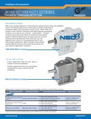
MODULAR SYSTEM<br />
TRANSMISSION TYPE ATTACHMENT ELEMENTS<br />
HELICAL FOOT MOUNT ELEKTIC MOTOR<br />
HELICAL FLANGE MOUNT<br />
SHAFT MOUNT REDUCER<br />
SHAFT MOUNT REDUCER<br />
WITH SOLID SHAFT<br />
WORM GEAR UNIT<br />
(FOOT MOUNT BASE)<br />
SHAFT MOUNT WORM GEAR UNIT<br />
BRAKING MOTOR<br />
FRICTION-WHEEL VARIABLE-<br />
SPEED GEAR MOTOR<br />
VARIABLE-SPEED GEAR<br />
MOTOR<br />
IEC ATTACHMENT CYLINDER<br />
FREE INPUT SHAFT HOUSING<br />
FLANGE MOUNT WORM GEAR UNIT DRIVE-END FLANGE<br />
HELICAL-BEVEL-GEAR UNIT CENTRIFUGAL CLUTCH/<br />
(FOOT MOUNT) COUPLING WITH OR<br />
WITHOUT BRAKE<br />
HELICAL-BEVEL-GEAR UNIT COMBINED COUPLING/<br />
SHAFT MOUNT CLUTCH AND BRAKE<br />
HELICAL-BEVEL-GEAR UNIT HELICAL SPEED REDUCER<br />
FLANGE MOUNT EXTREMLY LOW SPEEDS<br />
Getriebebau Nord<br />
Your Partner