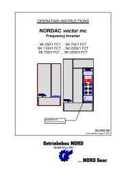
OPERATING INSTRUCTIONS NORDAC Frequency Inverters
OPERATING INSTRUCTIONS NORDAC Frequency Inverters
OPERATING INSTRUCTIONS NORDAC Frequency Inverters

You also want an ePaper? Increase the reach of your titles
YUMPU automatically turns print PDFs into web optimized ePapers that Google loves.
6.0 Commissioning<br />
Before switching on: - follow the accident prevention regulations<br />
- note to the safety regulations<br />
- take locally applicable safety measures<br />
- note the information in the operating instructions<br />
- check the power and control connections<br />
- install a disconnection facility (in case a malfunction occurs)<br />
- connect the motor in either a star or a delta circuit (depending on application)<br />
- disable the electronic circuit<br />
- set the setpoint at 0 V or alternatively 0(4) mA<br />
Caution !<br />
Ensure that persons, machines, and other valuable items are not endangered when the drive starts.<br />
This even applies in the event of a malfunction of the drive.<br />
Switching on: - switch on the inverter<br />
- set the voltage/frequency characteristic line (U/f characteristic) to correspond<br />
with the motor data - you will find some standard values below (option 12)<br />
- other voltage/frequency characteristic curves can be set between 30 and 999 Hz,<br />
in increments of 1 Hz<br />
Mains Rated voltage/frequency U/f-character. max.output voltage Circuit con- Factor of<br />
of motor of frequency inverter figuration power/speed<br />
(V) (V;Hz) (Hz) (V) increase<br />
1x230 V 230/400 V;50 Hz 50 Hz 220 V 1<br />
3x400 V 230/400 V;50 Hz 50 Hz 380 V 1<br />
3x400 V 230/400 V;50 Hz 87 Hz 380 V 1,73<br />
3x400 V 400/660 V;50 Hz 50 Hz 380 V 1<br />
3x400 V 400/380 V;50 Hz 50 Hz 380 V 1<br />
1x230 V 230/400 V;60 Hz 60 Hz 230 V 1<br />
3x400 V 230/400 V;60 Hz 60 Hz 400 V 1<br />
3x400 V 230/400 V;60 Hz 104 Hz 400 V 1,73<br />
1x240 V 240/415 V;50 Hz 50 Hz 240 V 1<br />
3x415 V 240/415 V;50 Hz 50 Hz 415 V 1<br />
3x415 V 240/415 V;50 Hz 87 Hz 415 V 1,73<br />
3x400 V 290/500 V;50 Hz 38 Hz 380 V 0,76<br />
3x400 V 290/500 V;50 Hz 66 Hz 380 V 1,31<br />
3x400 V 254/440 V;60 Hz 52 Hz 380 V 0,83<br />
Other combinations are possible in the same way.<br />
The relationship of stator voltage to frequency must remain constant:<br />
Inverter output voltage x rated frequency<br />
U/f characteristic = Motor rated voltage<br />
Example: Motor 230/400 V; Δ /' ; 50 Hz<br />
Circuit configuration 230 V Δ<br />
22<br />
400 V x 50 Hz<br />
U/f characteristic = = 87 Hz<br />
230 V<br />
- set fmin and fmax to low frequencies (e.g. 2 and 5 Hz)<br />
- go to start of program (at the same time, press first two buttons)<br />
- enable control release<br />
- check the starting current against the operating display (status display)<br />
- if current is too low / motor does not start ---> increase static boost<br />
- if current is too high / motor overloaded / inverter at current limit--><br />
reduce static boost<br />
- if necessary, divide static boost into part dynamic / part static boost<br />
(options 7 and 8)<br />
- check the control functions, e.g.:<br />
* direction of rotation of the motor<br />
* change of direction<br />
* signalling the frequency<br />
* switching the setpoint<br />
* disabling the circuitry<br />
* function of the electromagnetic brake<br />
* anything else<br />
- set the remaining parameters<br />
- increase the operating parameters step by step to the required final values<br />
- the values obtained for the static and , if necessary, the dynamic boost<br />
should not be changed again.