Getriebebau NORD - TracePartsOnline.net
Getriebebau NORD - TracePartsOnline.net
Getriebebau NORD - TracePartsOnline.net

You also want an ePaper? Increase the reach of your titles
YUMPU automatically turns print PDFs into web optimized ePapers that Google loves.
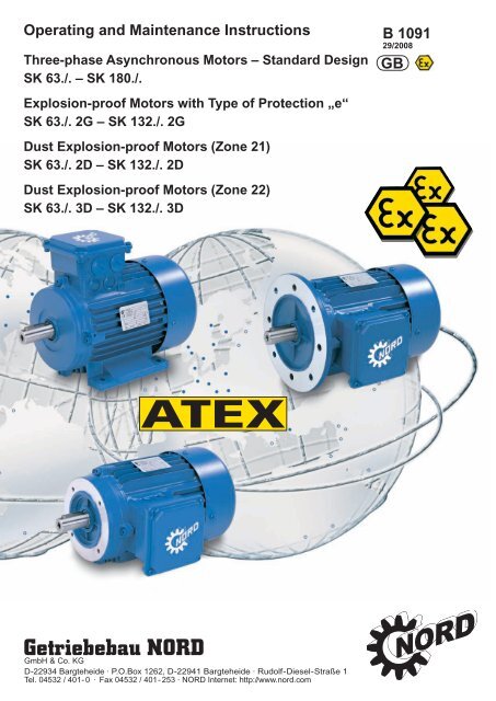
Operating and Maintenance Instructions<br />
Three-phase Asynchronous Motors – Standard Design<br />
SK 63./. – SK 180./.<br />
Explosion-proof Motors with Type of Protection „e“<br />
SK 63./. 2G – SK 132./. 2G<br />
Dust Explosion-proof Motors (Zone 21)<br />
SK 63./. 2D – SK 132./. 2D<br />
Dust Explosion-proof Motors (Zone 22)<br />
SK 63./. 3D – SK 132./. 3D<br />
<strong>Getriebebau</strong> <strong>NORD</strong><br />
GmbH & Co. KG<br />
D-22934 Bargteheide · P.O.Box 1262, D-22941 Bargteheide · Rudolf-Diesel-Straße 1<br />
Tel. 04532 / 401- 0 · Fax 04532 / 401- 253 · <strong>NORD</strong> Inter<strong>net</strong>: http://www.nord.com<br />
B 1091<br />
29/2008<br />
GB
Contents<br />
1. General information .............................................................................................................. 3<br />
2. Description ..............................................................................................................................4<br />
2.1 Range of application .................................................................................................................4<br />
3. Information on the designated use of electric motors .......................................................4<br />
3.1 Transport, storage.....................................................................................................................4<br />
3.2 Installation .................................................................................................................................5<br />
3.3 Balancing, output components..................................................................................................5<br />
3.4 Alignment ..................................................................................................................................5<br />
3.5 Electrical connection .................................................................................................................5<br />
3.6 Checking insulation resistance .................................................................................................6<br />
3.7 Commissioning..........................................................................................................................6<br />
4. Maintenance/servicing............................................................................................................7<br />
5. Motors with type of protection Increased Safety Exe .........................................................8<br />
6. Motors for use in Zone 21 and Zone 22 ..............................................................................10<br />
6.1 General....................................................................................................................................10<br />
6.2 Safety instructions...................................................................................................................10<br />
6.3 Commissioning instructions/range of application....................................................................10<br />
6.4 Design and method of operation.............................................................................................11<br />
6.5 Minimum cross-sections of protective earth wires ..................................................................11<br />
6.6 Maintenance............................................................................................................................11<br />
7. Options for motors for use in Zone 22................................................................................12<br />
7.1 Option inverter operation.........................................................................................................12<br />
7.2 Option external fan..................................................................................................................12<br />
7.3 Option return stop ...................................................................................................................12<br />
7.4 Option brake............................................................................................................................12<br />
8. Spare parts drawing and spare parts list ...........................................................................13<br />
9. Conformity declarations.......................................................................................................14<br />
10. Address list............................................................................................................................17<br />
Safety and information signs<br />
Please comply with the following safety and information signs!<br />
Danger!<br />
Danger to life and risk of<br />
injury for humans<br />
Danger!<br />
Important information<br />
for explosion protection<br />
Attention!<br />
Damage to the machine possible<br />
Information!<br />
-2- www.nord.com B1091-GB
1. Information<br />
1. General information<br />
These Operating Instructions must be read before you transport, assemble, commission,<br />
maintain or repair <strong>NORD</strong> motors. All persons who are involved with such tasks must observe<br />
these Operating Instructions. All safety instructions provided in these Operating Instructions<br />
must be strictly observed for reasons of personal protection and protection of property.<br />
Information and instructions provided in the manual supplied, safety and commissioning information<br />
and all other manuals must be observed.<br />
This is absolutely essential in order to avoid hazards and damage!<br />
Any applicable national, local and system-specific regulations and requirements must also be<br />
observed!<br />
Custom designs and design variants may differ on technical details. If any points are<br />
not clear, it is urgently recommended that you consult the manufacturer stating the<br />
type designation and motor number or have the maintenance work performed by<br />
<strong>NORD</strong>.<br />
Qualified staff are persons who, owing to their training, experience, instruction received, and<br />
their knowledge of relevant standards, accident prevention regulations and the appropriate<br />
operating conditions, are entitled to perform the activities necessary in order to put the motor<br />
into operation.<br />
That also calls for knowledge of First Aid and local rescue facilities. It is assumed that the<br />
work for transport, assembly, installation, commissioning, maintenance and repair will be performed<br />
by qualified staff.<br />
The following points in particular must be observed:<br />
• Specifications and information about permissible use, assembly, connection, ambient<br />
and operating conditions, which are included in the catalogue, the order documentation<br />
and any other product documentation<br />
• The local, system-specific regulations and requirements<br />
• Expert use of tools, hoisting equipment and transport equipment<br />
• Use of personal safety equipment<br />
For reasons of simplicity the Operating Instructions cannot contain all detailed information<br />
about possible design variants so they cannot take into consideration every imaginable case<br />
of installation, operation or maintenance.<br />
For this reason these Operating Instructions essentially only contain such instructions as are<br />
required for normal use by qualified staff. To prevent malfunctions it is necessary that the<br />
specified maintenance and inspection work be performed by appropriately trained staff.<br />
• The engineering guideline 605 2101 must be included with the operating instructions<br />
when operated with the inverter.<br />
• The additional operating instructions must be taken into account if an external fan is<br />
present.<br />
• The brake operating instructions must also be taken into account with braking motors.<br />
If, for any reason, the operating instructions or the engineering guidelines are lost, new documentation<br />
must be obtained from <strong>Getriebebau</strong> <strong>NORD</strong>.<br />
B1091-GB www.nord.com -3-
2.1 Range of application<br />
Use of the motors:<br />
2. Description<br />
3. Information<br />
The motors may only be used for their intended purpose.<br />
The motors are designed with at least IP 55 protection (for degree of protection see rating<br />
plate). They can be installed in a dusty or moist environment.<br />
The necessary degree of protection and any additional precautions required always depend<br />
on the operating and environmental conditions. For outdoor installation and vertical designs,<br />
e.g. V1 or V5 with shaft pointing down, <strong>NORD</strong> recommends using the option of the double fan<br />
hood [RDD].The motors must be protected against intense sunlight, e.g. by means of a protective<br />
roof. The insulation is tropic-proof.<br />
Installation height: ≤ 1000 m<br />
Ambient temperature: -20°C...+40°C. With standard motors, a greater ambient temperature<br />
range is permitted from -20°C...+60°C. The rated power must however be reduced to 82% of<br />
the catalogue value. If the maximum value of the ambient temperature is between +40°C and<br />
+60°C, the value of the power consumption can be inversely interpolated linearly between<br />
100% and 82%.<br />
The motor connection cables and the cable inlet glands must be suitable for temperatures ≥<br />
90°C.<br />
3. Information on the designated use of electric motors<br />
Work may only be performed if the system is disconnected from the mains supply.<br />
3.1 Transport, storage<br />
• For transport use all the hoisting lugs fitted to the motor!<br />
• The hoisting lugs are designed for the weight of the motor; do not attach any additional<br />
loads!<br />
• To transport machine sets (e.g. gear unit attachments) only use the hoisting lugs and<br />
pins provided!<br />
• Machine sets must not be hoisted by attaching to individual machines!<br />
To prevent damage to the motor, the motor must always be lifted with suitable hoisting<br />
equipment. The antifriction bearings should be replaced if the time between delivery and motor<br />
commissioning under favourable conditions (storage in dry, dust-free and vibration-free<br />
rooms) is more than 4 years. Under unfavourable conditions that time is reduced considerably.<br />
It may be necessary to treat unprotected, machine surfaces (flanging surface, shaft end;<br />
...) with corrosion inhibitor. If necessary, check the insulation resistance of the winding, see<br />
section 3.6.<br />
Changes in normal operation (higher power consumption, higher temperatures or higher vibrations,<br />
unusual noises or smells, response from the monitoring system, etc.) indicate that<br />
operation is impaired. To avoid personal injury and damage to property, the maintenance staff<br />
responsible must be informed about the change immediately.<br />
In case of doubt switch off the motor without delay, as soon as the status of the system permits.<br />
-4- www.nord.com B1091-GB
3. Information<br />
3.2 Installation<br />
• Screwed-in lifting eyes must either be screwed in fully or removed after erection!<br />
• Running smoothness: Precise alignment of the coupling and a well-balanced drive<br />
element (coupling, belt pulleys, fans, etc.) are prerequisites for quiet, low vibration<br />
operation.<br />
• Complete balancing of the motor with the drive elements may be necessary.<br />
• The upper section of the terminal box and the terminal box position can be rotated by<br />
4 x 90 degrees.<br />
• IEC-B14 motors:<br />
All four fixing screws, even if not required, must be screwed into the flanged bearing<br />
plate! The fixing screw threads must be inserted with a sealant, e.g. Loctite 242. The<br />
maximum screw-in depth in the bearing plate is 2 x d.<br />
3.3 Balancing, output components<br />
Fitting and removing output assemblies (coupling, pulleys, gear, ...) must be performed<br />
with a suitable device. The rotors are balanced with half key balancing as standard.<br />
When fitting output assemblies to the motor shaft observe the appropriate type of balancing!<br />
The output assemblies have to be balanced in accordance with DIN ISO 1940!<br />
Take the general precautions necessary for providing the output assemblies with shock protection.<br />
If a motor is put into operation without an output assembly, prevent the key from being<br />
flung out. This also applies if a second shaft end is fitted. Alternatively, remove the key.<br />
3.4 Alignment<br />
Especially if there is a direct coupling, align the shafts of the motor and the driven machine<br />
with one another axially and radially. Any inaccurate alignment can lead to bearing damage,<br />
excessive vibrations and shaft breakage.<br />
3.5 Electrical connection<br />
Feed the connecting leads into the terminal box with cable glands. The terminal box must be<br />
sealed so that it is dust-tight and water-tight. The mains voltage and mains frequency must<br />
agree with the figures on the rating plate. ± 5% voltage deviations or ± 2% frequency deviations<br />
are permissible without any reduction in performance. The connections and arrangement<br />
of the terminal board jumpers must conform to the circuit diagram provided in the terminal<br />
box. Connect the protective earth lead to that protective earth terminal.<br />
Provide the ends of the connecting leads with cable lugs or curved ring eyes and connect<br />
them to the terminal board. That also applies to the protective earth connection and the external<br />
bonding lead.<br />
For tightening torques at the screw connections of electric terminals and the terminal board<br />
connections (apart from terminal strips) refer to the table below:<br />
Tightening torques for terminal board connections<br />
Thread diameter M4 M5 M6 M8<br />
Tightening torque (Nm) 0,6 - 1,2 1,8 - 2,5 2,7 - 4,0 5,5 – 8,0<br />
If the machine has an auxiliary heater, it must not be switched on during operation.<br />
B1091-GB www.nord.com -5-
3. Information<br />
3.6 Checking insulation resistance<br />
Before putting the motor into operation for the first time, after a lengthy period of storage or<br />
standstill (approx. 6 months), the insulation resistance of the winding has to be determined.<br />
During and directly after measurement the terminals carry hazardous voltages in some cases<br />
and must not be touched.<br />
Insulation resistance<br />
The insulation resistance of new, cleaned, repaired windings against the housing and against<br />
one another is >200 M Ohm.<br />
Measurement<br />
In the case of windings up to an operating voltage of 400 V the insulation resistance against<br />
the housing must be measured with a DC voltage of 500 V. At operating voltages up to 725 V<br />
measure with a DC voltage of 1000 V. When doing this the temperature of the windings<br />
should be 25°C ± 15°C.<br />
Checking<br />
If, in the case of a new, cleaned winding or a repaired motor which has been stored or shut<br />
down for any lengthy period, the insulation resistance of the winding against the housing is<br />
less than 50 MOhm, the cause may be moisture. The windings will then have to be dried.<br />
After any lengthy period of operation the insulation resistance may drop. As long as the<br />
measured value does not fall below the critical insulation resistance of < 50 MOhm, the motor<br />
may continue to be operated. If the value falls below the critical level, the cause must be established<br />
and if necessary, the windings or winding sections must be repaired, cleaned or<br />
dried.<br />
3.7 Commissioning<br />
Note: Electromag<strong>net</strong>ic compatibility<br />
Emitted interference: If torques are not equal (e.g. drive of a piston compressor) a nonsinusoidal<br />
motor current is bound to develop, the harmonics of which may cause impermissible<br />
mains influence and hence impermissible emitted interference.<br />
If power is fed via an inverter, different levels of emitted interference will occur, depending on<br />
the design of inverter (type, suppression, manufacturer). It is absolutely essential that the<br />
EMC information provided by the inverter manufacturer be observed. If the manufacturer recommends<br />
a screened motor supply lead, screening will be most effective if it is electrically<br />
connected to a large area of the metal terminal box of the motor (with EMC cable gland made<br />
of metal). In the case of motors with built-in sensors (e.g. PTC thermistors) interference voltages<br />
can occur on the sensor line, caused by the inverter.<br />
Interference immunity: In the case of motors with built-in sensors (e.g. PTC thermistors) the<br />
user himself must ensure adequate interference immunity by making a suitable selection of<br />
sensor signal line (possibly with screening, interfacing as with motor supply lead) and the analysing<br />
instrument. Prior to commissioning always observe the information and instructions in<br />
the operating manuals for inverters as well as all other sets of instructions. After attaching the<br />
motors, check them to make sure they are operating properly! In the case of brake motors<br />
also check that the brake operates properly.<br />
-6- www.nord.com B1091-GB
4. Maintenance<br />
Servicing<br />
Safety precautions<br />
Before commencing any work on the motor or device, but especially before opening covers in<br />
front of live components, always isolate the motor electrically according to the regulations.<br />
Apart from the main circuits also isolate any additional or auxiliary circuits.<br />
The standard "5 safety rules", e.g. according to DIN VDE 0105, are:<br />
• Isolate electrically<br />
• Prevent equipment from being switched on again<br />
• Check that there is no voltage<br />
• Earth and short-circuit<br />
• Cover any adjacent live components or prevent access with barriers<br />
The above precautions may only be withdrawn when the maintenance work has been completed<br />
and the motor is fully assembled.<br />
Inspect the motors properly at regular intervals. In particular look out for any physical damage,<br />
ensure that cooling passages are free, listen for any unusual noises, and ensure that electrical<br />
connections are performed in a proper manner.<br />
With the exception of standardised, commercial or equivalent parts the only spare parts which<br />
may be used are genuine spare parts!<br />
NOTE: Inasmuch as motors are provided with enclosed condensation ports, they must be<br />
opened from time to time so that any accumulated condensation can drain off. Condensation<br />
ports are always positioned at the lowest point of the motor. When installing the motor ensure<br />
that the condensation holes are at the bottom.<br />
Bearing changes, grease filling<br />
The period for changing bearings in operating hours [h] on IEC motors with coupling drive is<br />
as follows, under normal operating conditions and with the motor installed horizontally, depending<br />
on coolant temperature and motor speed:<br />
25°C 40°C<br />
up to 1800 min -1<br />
approx. 40000 h approx. 20000 h<br />
up to 3600 min -1<br />
approx. 20000 h approx. 10000 h<br />
In the case of direct gearbox attachment or under special operating conditions, e.g. vertical<br />
motor, substantial vibrations or shock loads, frequent reversing, etc. the above-mentioned operating<br />
hours will be reduced considerably.<br />
The motor must be subjected to a general overhaul every 5 years!<br />
General overhaul<br />
For this purpose the motor must be dismantled. Perform the following work:<br />
• Clean all parts of the motor<br />
• Inspect all parts of the motor for damage<br />
• Replace all damaged parts<br />
• Replace all antifriction bearings<br />
• Replace all gaskets and shaft seals<br />
The general overhaul must be performed in a specialised workshop with appropriate equipment<br />
and by qualified staff. We urgently recommend having the general overhaul performed<br />
by <strong>NORD</strong> Service.<br />
B1091-GB www.nord.com -7-
5. Motors with protection type<br />
Increased Safety Exe<br />
These motors are subject to the following supplementary or specific information.<br />
The motors are suitable for use in Zone 1 and conform to equipment group II, category 2G, and can be used<br />
for an ambient temperature between -20°C and +40°C.<br />
Type addition: 2G e.g.: 80 L/4 2G TF<br />
The marking is 0102 II 2G Ex e II along with the temperature class<br />
If the motor is connected to a gearbox, the Ex marking of the gearbox must also be observed.<br />
Explosive gas mixtures or concentrations of dust in conjunction with hot, live and moving parts on electrical<br />
machinery can cause serious or lethal injuries.<br />
The increased hazard in explosive areas calls for particularly careful compliance with the general safety and<br />
commissioning instructions. The staff responsible must be trained regarding correct use of motors in<br />
explosive areas.<br />
Explosion-proof electrical machines comply with the standards in series EN 60034 (VDE 0530) as well as EN<br />
60079-0 and 60079-7. It is the degree of explosion risk which determines zone classification. DIN EN 60079,<br />
Part 10, provides information on this. It is the user who is responsible for zone classification.<br />
If motors are not certified for explosive areas, it is prohibited to use them in explosive areas.<br />
Cable entries must be approved for explosive atmospheres. Ports which are not used must be closed off with<br />
approved blind plugs.<br />
When connecting up the installation lines to the motor terminals and the protective earth lead must be laid<br />
with U-shaped lines under the respective terminals so that the wire clamps and the terminal studs are<br />
subjected to uniform loading and are not deformed under any circumstances. Alternatively, the connections<br />
can be made with a cable lug. The use of aluminium connecting cables is not permissible.<br />
When connecting up always ensure that the permissible clearance distances of 10 mm and the permissible<br />
creepage distances of 12 mm between live components and housing potential and between individual live<br />
components are observed.<br />
Before the terminal box is closed, make sure that all the nuts on the terminals and the screw on the<br />
protective earth terminal are tight. The terminal box gaskets and the seals on the cable gland must be fitted<br />
properly and must not be damaged in any way.<br />
If the shaft end is at the top, e.g. designs IMV3 or IMV6, and the motor has Exe protection, the user/installer<br />
must fit a cover which prevents foreign bodies from falling into the motor fan hood (see DIN EN 50014). It<br />
must not impair cooling of the motor by its fan. A handwheel at the second shaft end is not permitted. If the<br />
shaft end is at the bottom, e.g. designs IMV1 or IMV5, the motors are generally provided with a protective<br />
roof on the fan hood.<br />
The motors are designed for continuous duty and normal, non-recurring start-ups in which no substantial<br />
start-up heat develops.<br />
Area A in EN 60034-1 (VDE 0530 Part 1) - voltage ± 5%, frequency ± 2%, characteristic, mains symmetry -<br />
must be observed so that the development of heat remains within the limits permitted. Any major deviations<br />
from the ratings can caused an impermissible increase in the development of heat in the electric machine.<br />
The motor temperature class stated on the rating plate must at least conform to the temperature class of any<br />
combustible gas that may be emitted.<br />
Each machine must be protected against impermissible development of heat by a current-dependent<br />
delayed protective switch tested for operation by an appointed body, with phase-failure protection in<br />
compliance with VDE 0660 or an equivalent system in all phases. The protective system must be set to the<br />
rated current. If windings are connected in a delta circuit the trips must be connected in series with the<br />
winding phases and set to 0.58 times the rated current. If such a configuration is not possible, additional<br />
precautions will be necessary (e.g. thermal machine protection).<br />
-8- www.nord.com B1091-GB
5. Motors with protection type<br />
Increased Safety Exe<br />
If the rotor jams, the protective system must shut down within the tE-time specified for the respective<br />
temperature class. Electric machines for heavy starting (ramp time > 1.7 x tE-time) must be protected by a<br />
start-up monitoring system in accordance with the provisions of the EC type test certificate.<br />
Thermal machine protection by means of direct thermal monitoring of the winding with PTC thermistor<br />
temperature sensor is permissible if it is certified and stated on the rating plate.<br />
Do not connect any voltage higher than 30V to the PTC thermistor temperature sensor!<br />
If the only protection is a PTC thermistor temperature sensor, a performance-tested, certified PTC tripping<br />
unit from an appointed body must be used. The PTC tripping unit must be provided with the following marks<br />
concerning the degree of protection:<br />
II (2) G<br />
In Germany reference is made to DIN 57165/VDE 0165 and ElexV for setting up electrical installations<br />
in explosive areas! In other countries the appropriate national regulations must be observed!<br />
Operation in conjunction with an inverter must be explicitly certified. It is absolutely essential that the<br />
separate manufacturer's instructions be observed. For Exe protection the motor, inverter and protective<br />
systems must be identified as belonging together and the permissible operating data must be defined on the<br />
joint EC type test certificate. The levels of voltage peaks generated by the inverter may be subjected to<br />
unfavourable influences by the connecting cable installed between the inverter and the electric machine. In<br />
the system comprising inverter-cable-electric machine the maximum figure for voltage peaks at the<br />
connecting terminals on the machine must not be less than the figure specified in the separate<br />
manufacturer's instructions. In addition, the EMC Directive must also be observed.<br />
Any repairs must be performed by <strong>NORD</strong> or accepted by an officially recognised independent expert. The<br />
work must be identified by means of an additional repair plate. With the exception of standardised,<br />
commercial and equivalent parts, the only spare parts which may be used are genuine spare parts (see<br />
spare parts list): this particularly applies to seals and connecting parts.<br />
In the case of motors with closed condensation holes the threads of the plugs must be recoated with Loctite<br />
242 or Loxeal 82-21 after condensation has been drained off. As soon as that has been done the plugs must<br />
be reinserted. Checking of electrical connections must be performed at regular intervals.<br />
The connection terminals, protective earth terminal and equipotential bonding terminal must be inspected to<br />
make sure they are firm. When doing so, check to make sure that the cable entry, cable gland and terminal<br />
box gaskets are in good condition.<br />
All work on electric machines must be performed with the machine vertical and with all terminals<br />
disconnected from the mains.<br />
If installation resistance is being measured the motor must be removed. Measurement must not be performed<br />
in the explosive area. As soon as measurement has been completed discharge the connecting terminals<br />
again by shorting them in order to prevent any spark discharges occurring in the explosive area.<br />
B1091-GB www.nord.com -9-
6. Motors for use in Zone 21<br />
and Zone 22<br />
6.1 General information<br />
The following information applies additionally or especially to motors in categories 2D and 3D!<br />
The motors are suitable for use in Zone 21 (category 2D) or Zone 22 – non-conductive dusts (category 3D)<br />
according to their designation.<br />
Type addition: Zone 21: 2D e.g.: 80 L/4 2D TF<br />
Zone 22: 3D e.g.: 80 L/4 3D TF<br />
The designation is as follows: 0102 II 2 D T 125°C for category 2 (Zone 21)<br />
Certification number: BVS 04 ATEX E 037<br />
II 3 D T 125°C for category 3 (Zone 22 non-conductive dust)*<br />
* the details of the surface temperature may deviate from 125°C and may be obtained from the identification<br />
plate<br />
If the motor is connected to a gear, the Ex designation of the gear must also be taken into account!<br />
6.2 Safety information<br />
The increased danger in areas with combustible dust requires that the general safety and commissioning<br />
instructions are strictly complied with. Explosive dust concentrations can cause explosions if ignited by hot or<br />
sparking objects and this can cause severe or even lethal injuries to persons and significant damage to<br />
property.<br />
It is absolutely essential that the persons authorised to use these motors in hazardous areas are trained in<br />
their correct use.<br />
6.3 Commissioning instructions / application area<br />
The motors are suitable for use in Zone 21 (category 2D) or Zone 22 – non-conductive dusts (category 3D)<br />
according to their designation. If the motors are intended for inverter operation, this must be specified when<br />
ordering. The motors must be protected against overheating with suitable monitoring equipment! The dust<br />
levels must not exceed 5 mm! The motors are designed for the voltage and frequency range A as in EN<br />
60034 Part 1.<br />
Electrical equipment for use in areas with combustible dust complies with the standards EN 50281-1-1, EN<br />
60034 and EN 50014. The level of explosion hazard is determined by the zone separation. The<br />
operator/employer is responsible for zone separation (guideline 1999/92/EC).<br />
If the designation is supplemented by an X, special documentation in the EC type examination certificate<br />
must be complied with. It is forbidden to use standard motors in hazardous areas that are not authorised for<br />
use in hazardous areas. In Zone 21, the cable entries must be authorised for Ex areas (protection class<br />
minimum IP 66) and must be secured against accidental loosening. Unused apertures must be sealed with<br />
authorised plugs (minimum protection class IP 66).<br />
In Zone 22, the cable entries must meet at least protection class IP 55. Unused apertures must be sealed<br />
with blind plugs (minimum protection class IP 55).<br />
The motor must not be opened under hazardous atmospheres to connect the electrical cables or for any<br />
other work. The voltage must always be switched off and secured against being switched on again before<br />
opening the motor!<br />
The permissible ambient temperature range for all motors is -20°C...+40°C. A greater ambient temperature<br />
range of -20°C...+60°C is permissible with motors for operation in Zones 21 and 22. This does not however<br />
apply with the option brake and external fans! The rated power must then be reduced to 72% of the catalogue<br />
value. If the maximum value of the ambient temperature is between +40°C and +60°C, the value of the<br />
power consumption can be inversely interpolated linearly between 100% and 72%. Thermal motor protection<br />
with a PTC temperature sensor is essential here. The motor connection cables and the cable glands must be<br />
suitable for temperatures ≥ 90°C.<br />
-10- www.nord.com B1091-GB
6. Motors for use in Zone 21<br />
and Zone 22<br />
IEC-B14 motors<br />
The B14 flanged bearing plate must be covered with a protective foil which must be removed before the motor<br />
is fastened in place. All four fixing screws, even if not required, must be screwed into the flanged bearing<br />
plate! The fixing screw threads must be inserted with a sealant, e.g. Loctite 242. The maximum screw-in<br />
depth in the bearing plate is 2 x d.<br />
If the shaft end faces upwards, e.g. models IMV3, IMV6, a cover must be positioned on the motor by the<br />
operator/installer to prevent foreign bodies from falling into the motor ventilation cover (see DIN EN 50 280-<br />
1-1). It must not hinder the motor from being cooled by the fans. Where shaft ends face down, e.g. models<br />
IMV1, IMV5, the motors for Zone 21 are generally equipped with a protective roof on the ventilation cover. A<br />
handwheel on the second shaft end is not permitted.<br />
Unless otherwise specified for operating modes and tolerances in the test certificate or rating plate, electrical<br />
machinery is designed for continuous operation and normal infrequent start-ups where insignificant start-up<br />
heating occurs. The motors may only be used for the operating mode specified on the rating plate.<br />
The installation regulations must be complied with!<br />
6.4 Structure and operating mode<br />
The motors are self-cooling. Rotary shaft seals are fitted both on the drive side (DS) and on the ventilation<br />
side (VS).<br />
Motors for Zone 21 and Zone 22 have metal fans. The motors are designed for protection class IP 55 (Zone<br />
22 – non-conductive dust) or IP 66 (Zone 21). Under normal operating conditions the surface temperature<br />
does not exceed that stated on the identification plate.<br />
6.5 Minimum cross-sections of ground leads<br />
Cross-section of phase conductor<br />
in installation S in mm 2<br />
Minimum cross-section of the associated<br />
ground lead SP in mm 2<br />
S ≤ 16<br />
S<br />
16 < S ≤ 35<br />
16<br />
S > 35<br />
0,5 S<br />
When connecting a lead to the external ground, the minimum cross-section must be 4 mm 2 .<br />
6.6 Maintenance<br />
The voltage must always be switched off and secured against being switched on again!<br />
Attention! Higher temperatures than the maximum permitted surface temperature of the housing may<br />
be present inside the motor. The motor must therefore never be opened in hazardous dust<br />
atmospheres!<br />
The motors must be checked and tested regularly for functional safety! The applicable national<br />
standards and regulations must be complied with!<br />
Unpermitted high dust deposits > 5 mm may not be allowed to build up! If functional safety cannot be<br />
ensured, the motor may not be operated!<br />
When the ball bearings are replaced, the rotary shaft seals must also be replaced. FKM rotary shaft seals as<br />
specified by <strong>Getriebebau</strong> <strong>NORD</strong> must be used. Ensure that they are fitted correctly!<br />
The rotary shaft seals must be lubricated on the external rings and on the seal lips. If an explosion protected<br />
gear is flanged dust-tight to the motor, an NBR rotary shaft seal can be used on the drive side of the motor if<br />
the gear oil temperature does not exceed 85°C.<br />
Only original parts may be used as spare parts with the exception of standardised, commercially available<br />
and equivalent parts. This also applies in particular to seals and connection components. Parts for terminal<br />
boxes or spare parts for external grounding must be ordered as per the spare parts list in the operating<br />
instructions.<br />
The functionality of seals, rotary shaft seals and cable glands must be regularly checked!<br />
Maintaining dust protection for the motors is of paramount importance for explosion protection.<br />
Maintenance must be implemented by qualified personnel in a specialist workshop with suitable equipment.<br />
We urgently recommend that general overhauls are implemented by <strong>NORD</strong> Service.<br />
B1091-GB www.nord.com -11-
7. Options for motors used in<br />
Zone 22<br />
7.1 Option inverter operation<br />
ATEX <strong>NORD</strong> motors for Zone 22 are suitable for inverter operation due to their insulation system design.<br />
Because of the variable rpm range, temperature monitoring with PTC resistors or temperature monitors is<br />
necessary. For safe engineering and application, comply with the engineering guideline "Operation of ATEX<br />
motors with frequency inverters", No. 605 2101. The engineering guideline provides information about the<br />
necessary requirements for inverter operation and about the permitted rpm ranges.<br />
7.2 Option external fan<br />
Motors with the additional designation F (e.g. 80S/4 3D F) are equipped with an external fan and must be<br />
monitored via the integrated temperature sensor.<br />
Attention!<br />
The motor may only be operated together with the external fan! A failure of the external fan can lead to the<br />
motor overheating and therefore endanger property/persons.<br />
Comply with the operating instructions for the external fan!<br />
The power supply for the external fan is provided independently via the external fan terminal box. The external<br />
fan power supply must be identical to the voltage rating given on the rating plate. The external fans must<br />
be protected against overheating with suitable monitoring equipment! The IP protection classes of the external<br />
fan and motor may be different. The lower IP protection class applies to the drive unit. The cable glands<br />
must meet at least the protection class IP55. Unused apertures must be sealed with blind plugs (minimum<br />
protection class IP55).<br />
External fans and motors for use in hazardous areas have an Ex designation as per guideline 94/9 EC. This<br />
designation must be present on the external fan and on the motor. If the designations of the external fan and<br />
the motor differ, the lowest designated explosion protection applies to the entire drive. The maximum<br />
specified temperature given in the surface temperature data for the individual components applies for the<br />
entire drive unit In this case, it may be necessary to take into account any gears that may be present.<br />
Contact <strong>Getriebebau</strong> <strong>NORD</strong> if there are any doubts.<br />
If any component in the entire drive does not have an Ex designation, then the entire drive may not be operated<br />
in an Ex area.<br />
7.3 Option return stop<br />
Motors with the additional designation RLS (e.g. 80S/4 3D RLS) are equipped with a return stop.<br />
Motors with return stops have an arrow marking the direction of rotation on the ventilation cover. The arrow<br />
points in the rotation direction of the motor. It must be ensured, when connecting the motor and during motor<br />
control, that the motor can only operate in the rotation direction, e.g. by means of a rotary field test. Switching<br />
the motor to the blocked rotation direction, i.e. incorrect rotation direction, can lead to damage.<br />
Return stops operate without wear from a speed of ca. 800 1/min.. Return stops must not be operated at<br />
speeds under 800 l/min to prevent unpermitted heating and rapid wear of the return stop. This must be taken<br />
into account for motors with a frequency of 50 Hz and poles ≥ 8, and for motors with frequency inverters.<br />
7.4 Option brake<br />
Motors with the additional designation BRE (e.g. 80S/4 3D BRE 10) are equipped with a brake and must be<br />
monitored via the integrated temperature sensor. If the temperature sensor of one of the components (motor<br />
or brake) is triggered, the entire drive must be securely shutdown. The motor and brake PTC's must be<br />
switched in series.<br />
Attention!<br />
The brake DC voltage supply must be implemented via a rectifier located in the motor terminal box or via a<br />
directly supplied voltage. The brake voltage shown on the rating plate must be complied with.<br />
The power supply lines must not be laid in a cable together with the temperature sensor circuit. The brake<br />
functionality must be checked before start-up. There should be no grinding noises, as this could lead to<br />
unpermitted excessive heating.<br />
-12- www.nord.com B1091-GB
8. Spare parts drawing and<br />
spare parts list<br />
Item No. Description Item No. Description<br />
900 Rotor with shaft<br />
902 End shield at drive end<br />
902.1 Cheese-head screw<br />
902.2 Hexagon nut<br />
904 Shaft seal<br />
905 Bearing at drive end<br />
906 Ball bearing shim<br />
907 Terminal box frame<br />
907.1 Chassis connection terminal wire clamp<br />
907.2 Oval-head screw<br />
908 Terminal box lid<br />
908.1 Cheese-head screw<br />
909 Terminal box frame gasket<br />
910 Terminal box lid gasket<br />
911 Terminal board<br />
911.1 Cheese-head screw<br />
911.5 Spring lock washer<br />
912 Mini-terminal<br />
912.1 Oval-head screw<br />
913 Spacer<br />
913.1 Cheese-head screw<br />
913.2 Spring lock washer<br />
916 Stator with winding<br />
916.1 Equipotential bonding terminal<br />
916.2 Spring pin<br />
918 Key<br />
924 Screw-on foot (BG 100-132)<br />
924.1 Hexagon bolt<br />
924.2 Spring lock washer<br />
924.3 Hexagon nut<br />
929 Bearing at ventilation end<br />
932 End shield at ventilation end<br />
932.1 Cheese-head screw<br />
932.2 Hexagon nut<br />
933 Shaft seal<br />
939 Fan<br />
940 Fan hood<br />
940.1 Oval-head screw<br />
940.2 Countersink screw B3<br />
941 Key<br />
942 947 Circlip<br />
948 Circlip<br />
952 Clamping bush<br />
953 Cable gland<br />
955 Blind plug<br />
956 Blind plug<br />
980 Protective roof<br />
988 Ring seal<br />
989 Rating plate<br />
989.1 Oval-head screw<br />
B1091-GB www.nord.com -13-
9. Conformity declaration<br />
-14- www.nord.com B1091-GB
9. Conformity declaration<br />
B1091-GB www.nord.com -15-
9. Conformity declaration<br />
-16- www.nord.com B1091-GB
<strong>Getriebebau</strong> <strong>NORD</strong> branches in Germany:<br />
10. Address list<br />
Niederlassung Nord <strong>Getriebebau</strong> <strong>NORD</strong> GmbH & Co. KG Tel.: 0 45 32 / 40 10<br />
Hamburg / Schleswig-Holstein / Postfach 12 62 · 22943 Bargteheide Fax: 0 45 32 / 40 12 53<br />
Niedersachsen / nördl. Hessen Rudolf-Diesel-Straße 1 NL-Bargteheide@nord-de.com<br />
22941 Bargteheide<br />
Vertriebsbüro Bremen <strong>Getriebebau</strong> <strong>NORD</strong> GmbH & Co. KG Tel.: 042 49 / 96 16 75<br />
westliches Niedersachsen / Vertriebsbüro Bremen Fax: 042 49 / 96 16 76<br />
Bremen Wohlers Feld 16 NL-Bremsen@nord-de.com<br />
27211 Bassum<br />
Vertriebsbüro Hannover <strong>Getriebebau</strong> <strong>NORD</strong> GmbH & Co.KG Tel.: 04532 / 40 10<br />
südl. Niedersachen / Hannover / Postfach 1262 · 22943 Bargteheide Fax: 0 45 32 / 40 12 53<br />
Niedersachsen / nördl. Hessen Rudolf-Diesel-Straße 1 info@nord-de.com<br />
Kassel 22941 Bargteheide<br />
Niederlassung West <strong>Getriebebau</strong> <strong>NORD</strong> GmbH & Co. KG Tel.: 02 11 / 995 55 0<br />
Köln / Koblenz / Niederlassung West Fax: 02 11 / 995 55 45<br />
südl. Nordrhein-Westfalen / Großenbaumer Weg 10 NL-Duesseldorf@nord-de.com<br />
Ruhrgebiet / Düsseldorf 40472 Düsseldorf<br />
Vertriebsbüro Butzbach <strong>Getriebebau</strong> <strong>NORD</strong> GmbH & Co. KG Tel.: 060 33 / 96 23 0<br />
Hessen / Frankfurt / Vertriebsbüro Butzbach Fax: 060 33 / 96 23 30<br />
Wiesbaden / Darmstadt Marie-Curie-Straße 2 NL-Frankfurt@nord-de.com<br />
35510 Butzbach<br />
Niederlassung Ost <strong>Getriebebau</strong> <strong>NORD</strong> GmbH & Co. KG Tel.: 03 71 / 33 40 70<br />
Sachsen / südl. Sachsen-Anhalt / Niederlassung Ost Fax: 03 71 / 33 40 720<br />
Thüringen Leipziger Straße 58 NL-Chemnitz@nord-de.com<br />
09113 Chemnitz / Sachsen<br />
Vertriebsbüro Berlin <strong>Getriebebau</strong> <strong>NORD</strong> GmbH & Co. KG Tel.: 030 / 63 97 94 13<br />
Berlin / Brandenburg Vertriebsbüro Berlin Fax: 030 / 63 97 94 14<br />
Mecklenb.-Vorpommern / Heinrich-Mann-Str. 8 NL-Berlin@nord-de.com<br />
nördl. Sachsen-Anhalt 15566 Schöneiche<br />
Niederlassung Süd <strong>Getriebebau</strong> <strong>NORD</strong> GmbH & Co. KG Tel.: 071 58 / 95 60 80<br />
Stuttgart / Baden-Würtemberg / Niederlassung Süd Fax: 071 58 / 95 60 820<br />
Saarland / südl. Rheinland-Pfalz Katharinenstr. 2-6 NL-Stuttgart@nord-de.com<br />
70794 Filderstadt – Sielmingen<br />
Vertriebsbüro München <strong>Getriebebau</strong> <strong>NORD</strong> GmbH & Co. KG Tel.: 089 / 840 794 0<br />
München / Süd-Bayern Vertriebsbüro München Fax: 089 / 840 794 20<br />
Untere Bahnhofstraße 29° NL-Muenchen@nord-de.com<br />
82110 Germering<br />
Vertriebsbüro Nürnberg <strong>Getriebebau</strong> <strong>NORD</strong> GmbH & Co. KG Tel.: 09 11 / 67 23 11<br />
Nürnberg / Nord-Bayern Vertriebsbüro Nürnberg Fax: 09 11 / 67 24 71<br />
Schillerstraße 3 NL-Nuernberg@nord-de.com<br />
90547 Stein<br />
Vertretung in Deutschland:<br />
Osnabrück / Bielefeld / Hans-Hermann Wohlers Tel.: 057 32 / 40 72<br />
Münster Handelsgesellschaft mbH Fax: 057 32 / 1 23 18<br />
Ellerbuscher Straße 177 a NL-Bielefeld@nord-de.com<br />
32584 Löhne<br />
B1091-GB www.nord.com -17-
<strong>Getriebebau</strong> <strong>NORD</strong> International:<br />
Austria / Österreich<br />
<strong>Getriebebau</strong> <strong>NORD</strong> GmbH<br />
Deggendorfstr. 8<br />
AT - 4030 Linz<br />
Tel.: +43-732-318 920<br />
Fax: +43-732-318 920 85<br />
info@nord-at.com<br />
Canada / Kanada<br />
<strong>NORD</strong> Gear Limited<br />
41, West Drive<br />
CA - Brampton, Ontario, L6T 4A1<br />
Tel.: +1-905-796-3606<br />
Fax: +1-905-796-8130<br />
info@nord-ca.com<br />
Croatia / Kroatien<br />
<strong>NORD</strong> Pogoni d.o.o.<br />
Obrtnicka 9<br />
HR - 48260 Krizevci<br />
Tel.: +385-48 711 900<br />
Fax: +385-48 270 494<br />
info@nord-hr.com<br />
Finland / Finnland<br />
<strong>NORD</strong> Gear Oy<br />
Aunankorvenkatu 7<br />
FI - 33840 Tampere<br />
Tel.: +358-3-254 1800<br />
Fax: +358-3-254 1820<br />
info@nord-fi.com<br />
Hungary / Ungarn<br />
<strong>NORD</strong> Hajtastechnika Kft.<br />
Törökkö u. 5-7<br />
HU - 1037 Budapest<br />
Tel.: +36-1-437-0127<br />
Fax: +36-1-250-5549<br />
info@nord-hu.com<br />
Italy / Italien<br />
<strong>NORD</strong> Motoriduttori s.r.l.<br />
Via Newton 22<br />
IT - 40017 San Giovanni in Persiceto (BO)<br />
Tel.: +39-051-6870 711<br />
Fax: +39-051-6870 793<br />
info@nord-it.com<br />
Norway / Norwegen<br />
<strong>NORD</strong> Gear Norge A/S<br />
Solgaard Skog 7, PB85<br />
NO - 1501 Moss<br />
Tel.: +47-69 20 69 90<br />
Fax: +47-69 20 69 93<br />
MHansen@nord-no.com<br />
10. Address list<br />
Belgium / Belgien<br />
<strong>NORD</strong> Aandrijvingen Belgiё N.V.<br />
Boutersemdreef 24<br />
BE - 2240 Zandhoven<br />
Tel.: +32-3-4845 921<br />
Fax: +32-3-4845 924<br />
info@nord-be.com<br />
P.R. China / V. R. China<br />
<strong>NORD</strong> (Beijing) Power Transmission Co.Ltd.<br />
No. 5 Tangjiacun,<br />
Guangqudonglu, Chaoyangqu<br />
CN - Beijing 100022<br />
Tel.: +86-10-67704 -305<br />
Fax: +86-10-67704 -330<br />
Info@nord-cn.com<br />
zech. Republic / Tschechien<br />
<strong>NORD</strong> Pohánĕcí Technika s.r.o<br />
Palackého 359<br />
CZ - 50003 Hradec Králové<br />
Tel.: +420 495 58 03 -10 (-11)<br />
Fax: +420 495 58 03 -12<br />
hzubr@nord-cz.com<br />
France / Frankreich<br />
<strong>NORD</strong> Réducteurs sarl.<br />
17 Avenue Georges Clémenceau<br />
FR - 93421 Villepinte Cedex<br />
Tel.: +33-1-49 63 01 89<br />
Fax: +33-1-49 63 08 11<br />
info@nord-fr.com<br />
India /Indien<br />
<strong>NORD</strong> Drivesystems Pvt. Ltd.<br />
282/ 2, 283/2, Plot No. 15<br />
Mauje, Village Mann<br />
Tal Mulshi, Adj. Hinjewadi Phase- II<br />
Pune Maharashtra 411 057<br />
Phone: +91-20-39801200<br />
Fax: +91-20-39801216<br />
info@nord-in.com<br />
Mexico / Mexiko<br />
<strong>NORD</strong> DRIVE SYSTEMS SA DE CV<br />
Av. Lázaro Cárdenas 1007 Pte.<br />
San Pedro Garza Garcia, N.L.<br />
México, C.P. 66266<br />
Phone: +52-81-8220-9165<br />
Fax: +52-81-8220-9044<br />
HGonzalez@nord-mx.com<br />
Poland / Polen<br />
<strong>NORD</strong> Napêdy Sp. z.o.o.<br />
Ul. Grottgera 30<br />
PL – 32-020 Wieliczka<br />
Tel.: +48-012-288 99 00<br />
Fax: +48-012-288 99 11<br />
biuro@nord.pl<br />
Brazil / Brasilien<br />
<strong>NORD</strong> Motoredutores do Brasil Ltda.<br />
Rua Dr. Moacyr Antonio de Morais,<br />
Parque Santo Agostinho<br />
Guarulhos – São Paulo<br />
BR:CEP 07140 - 285<br />
Tel.: +55-11-64 02 8855<br />
Fax: +55-11-64 02 8830<br />
info@nord-br.com<br />
P.R. China / V. R. China<br />
<strong>NORD</strong> (Suzhou)<br />
Power Transmission Co. Ltd.<br />
No.510 Changyang Street<br />
Suzhou Ind. Park<br />
Jiangsu 215021<br />
Phone: +86-512-85180277<br />
Fax: +86-512-85180278<br />
Info@nord-cn.com<br />
Denmark / Dänemark<br />
<strong>NORD</strong> Gear Danmark A/S<br />
Kliplev Erhvervspark 28 – Kliplev<br />
DK - 6200 Aabenraa<br />
Tel.: +45 73 68 78 00<br />
Fax: +45 73 68 78 10<br />
info@nord-dk.com<br />
Great Britain / Großbritannien<br />
<strong>NORD</strong> Gear Limited<br />
11, Barton Lane<br />
Abingdon Science Park<br />
GB - Oxfordshire OX 14 3NB<br />
Tel.: +44-1235-5344 04<br />
Fax: +44-1235-5344 14<br />
info@nord-uk.com<br />
Indonesia / Indonesien<br />
PT <strong>NORD</strong> Indonesia<br />
Jln. Raya Serpong KM. 7<br />
Kompleks Rumah Multi Guna Blok D No. 1<br />
Pakulonan (Serpong) - Tangerang<br />
ID - West Java - Indonesia<br />
Tel.: +62-21-5312 2222<br />
Fax: +62-21-5312 2288<br />
info@nord-id.com<br />
Netherlands / Niederlande<br />
<strong>NORD</strong> Aandrijvingen Nederland B.V.<br />
Voltstraat 12<br />
NL - 2181 HA Hillegom<br />
Tel.: +31-2525-29544<br />
Fax: +31-2525-22222<br />
info@nord-nl.com<br />
Portugal / Portugal<br />
<strong>NORD</strong> Motorreductores<br />
Apdo de Correos 166,<br />
ES-08200 Sabadell - Spain<br />
Phone: +34-93-723 5322<br />
Fax: +34-93-723 3147<br />
info@nord-es.com<br />
-18- www.nord.com B1091-GB
<strong>Getriebebau</strong> <strong>NORD</strong> International:<br />
Russian / Russland<br />
OOO <strong>NORD</strong> PRIVODY<br />
Ul.A. Nevsky 9<br />
RU - 191167 St. Petersburg<br />
Tel.: +7-812-327 0192<br />
Fax: +7-812-327 0192<br />
info@nord-ru.com<br />
Spain / Spanien<br />
<strong>NORD</strong> Motorreductores S.A.<br />
Aptdo. de Correos 166<br />
ES - 08200 Sabadell<br />
Tel.: +34-93-723 53 22<br />
Fax: +34-93-723 31 47<br />
info@nord-es.com<br />
Turkey / Türkei<br />
<strong>NORD</strong>-Remas Redüktör San. ve Tic. Ltd. Sti.<br />
Tepeören Köyü<br />
TR - 34959 Tuzla – Istanbul<br />
Tel.: +90-216-304 13 60<br />
Fax: +90-216-304 13 69<br />
info@nord-tr.com<br />
10. Address list<br />
Singapore / Singapur<br />
<strong>NORD</strong> Gear Pte. Ltd.<br />
33 Kian Teck Drive, Jurong<br />
SG- Singapore 628850<br />
Tel.: +65-6265 9118<br />
Fax: +65-6265 6841<br />
info@nord-sg.com<br />
Sweden / Schweden<br />
<strong>NORD</strong> Drivsystem AB<br />
Ryttargatan 277 / Box 2097<br />
SE - 19402 Upplands Väsby<br />
Tel.: +46-8-594 114 00<br />
Fax: +46-8-594 114 14<br />
info@nord-se.com<br />
Ukraine<br />
<strong>Getriebebau</strong> <strong>NORD</strong> GbmH<br />
Repräsentanz<br />
Vasilkovskaja, 1, Office 306<br />
UA - 03040 Kiew<br />
Tel.: +380-44-537 0615<br />
Fax: +380-44-537 0615<br />
vtsoka@nord-ukr.com<br />
Slowakia / Slowakei<br />
<strong>NORD</strong> Pohony, s.r.o<br />
Stromová 13<br />
SK - 83101 Bratislava<br />
Tel.: +421-2-547 913 17<br />
Fax: +421-2-547 914 02<br />
info@nord-sk.com<br />
Switzerland / Schweiz<br />
<strong>Getriebebau</strong> <strong>NORD</strong> AG<br />
Bächigenstr. 18<br />
CH - 9212 Arnegg<br />
Tel.: +41-71-388 99 11<br />
Fax: +41-71-388 99 15<br />
info@nord-ch.com<br />
United States / USA<br />
<strong>NORD</strong> Gear Corporation<br />
800 Nord Drive / P.O. Box 367<br />
US - Waunakee, WI 53597<br />
Tel.: +1-888-314-6673<br />
Fax: +1-800-373-6673<br />
info@nord-us.com<br />
B1091-GB www.nord.com -19-
www.nord.com<br />
Mat.-Nr. 605 13 02 / 29 08