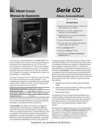
Operating Instructions CQ Series - Meyer Sound Laboratories Inc.
Operating Instructions CQ Series - Meyer Sound Laboratories Inc.
Operating Instructions CQ Series - Meyer Sound Laboratories Inc.

Create successful ePaper yourself
Turn your PDF publications into a flip-book with our unique Google optimized e-Paper software.
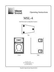
<strong>Operating</strong> <strong>Instructions</strong><br />
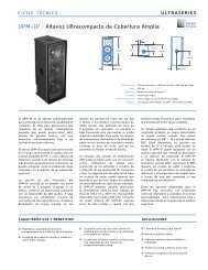
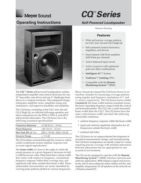
The <strong>CQ</strong> <strong>Series</strong> self-powered loudspeakers contain<br />
independent amplifier and control electronics for one<br />
15” bass-reflex cone driver and one 4” diaphragm horn<br />
driver in a compact enclosure. This integrated design<br />
eliminates amplifier racks, simplifies setup and<br />
installation, and improves durability and reliability.<br />
The <strong>CQ</strong> <strong>Series</strong>, consisting of the <strong>CQ</strong>-1 (low Q) and<br />
<strong>CQ</strong>-2 (high Q), are efficient full-range speakers and<br />
ideal companions for the PSW-2, PSW-4, and 650-P<br />
self-powered subwoofers. The <strong>CQ</strong> <strong>Series</strong> have the<br />
following acoustical specifications:<br />
Frequency Response ±4 dB 40 Hz – 18 kHz<br />
Phase Response ±90° 50 Hz – 16 kHz<br />
Max Peak SPL at 1 m <strong>CQ</strong>-1: 136 dB; <strong>CQ</strong>-2: 139 dB<br />
Dynamic Range > 110 dB<br />
The <strong>CQ</strong> is phase-corrected through the crossover, which<br />
yields exceptional system impulse response and<br />
accurate signal reproduction.<br />
The beam width of a horn is the angle at which the<br />
sound pressure at a given frequency decreases to half<br />
(–6 dB) its on-axis value. Most horns have a beam width<br />
that varies with respect to frequency, nonuniform<br />
frequency response within their coverage area, and<br />
significant side lobes outside their beam width. These<br />
undesirable characteristics are easily identified by<br />
viewing polar patterns plotted at various frequencies.<br />
<strong>CQ</strong><br />
<br />
<strong>Series</strong><br />
Self-Powered Loudspeaker<br />
Patents Pending<br />
Features<br />
• Wide and narrow overage patterns<br />
for <strong>CQ</strong>-1 (low Q) and <strong>CQ</strong>-2 (high Q)<br />
• Self-contained control electronics,<br />
amplifiers, and drivers<br />
• Dual-channel 1240 Watt amplifier<br />
(620 Watts per channel)<br />
• Active balanced input circuit<br />
• Active crossover with optimized<br />
pole-zero filter combinations<br />
• Intelligent AC System<br />
• TruPower Limiting (TPL)<br />
• Compatible with the Remote<br />
Monitoring System (RMS)<br />
<strong>Meyer</strong> <strong>Sound</strong> developed the <strong>CQ</strong> <strong>Series</strong> horns in an<br />
anechoic chamber by measuring coverage patterns<br />
using angular and frequency resolutions of 1° and<br />
1 ⁄24 octave, respectively. The <strong>CQ</strong> <strong>Series</strong> horns exhibit<br />
Constant Q: the beam width remains consistent across<br />
the horn’s operating frequency range in both the vertical<br />
and horizontal planes. The <strong>CQ</strong>-1 has a wider horizontal<br />
beam width than the <strong>CQ</strong>-2. The <strong>CQ</strong> <strong>Series</strong> have the<br />
same vertical beam width and share the following<br />
remarkable attributes:<br />
• uniform frequency response within the beam width<br />
• rapid and uniform amplitude attenuation for all<br />
frequencies outside the beam width<br />
• minimal side lobes<br />
The <strong>CQ</strong> horns are an unprecedented development in<br />
acoustical measurement, design, and manufacturing.<br />
The <strong>CQ</strong> <strong>Series</strong> loudspeakers are ideally suited for venues<br />
requiring precise coverage with minimal interaction<br />
between subsystems but are appropriate for any<br />
acoustical environment.<br />
The <strong>CQ</strong> can be equipped to operate with the Remote<br />
Monitoring System (RMS) interface network and<br />
software application. RMS displays signal and power<br />
levels, driver and cooling fan status, limiter activity, and<br />
amplifier temperature for all speakers in the network on<br />
a Windows-based PC.
2<br />
These symbols indicate important safety or operating features in this booklet and on the chassis.<br />
Dangerous voltages:<br />
risk of electric shock<br />
Pour indiquer les risques<br />
résultant de tensions<br />
dangereuses<br />
Zu die gefahren von<br />
gefährliche spanning zeigen<br />
Para indicar azares provengo<br />
de peligroso voltajes<br />
The Manufacturer:<br />
Made by <strong>Meyer</strong> <strong>Sound</strong>, Berkeley, CA, USA<br />
European Office:<br />
<strong>Meyer</strong> <strong>Sound</strong> Germany<br />
GmbH<br />
Carl Zeiss Strasse 13<br />
56751 Polch, Germany<br />
!<br />
Important operating<br />
instructions<br />
Pour indequer important<br />
instructions<br />
Zu wichtige betriebsanweisung<br />
und unterhaltsanweisung<br />
zeigen<br />
Para indicar importante<br />
funcionar y mantenimiento<br />
instrucciones<br />
Name: <strong>Meyer</strong> <strong>Sound</strong> <strong>Laboratories</strong><br />
Address: 2832 San Pablo Avenue<br />
Berkeley, California 94702-2204, USA<br />
conforms to the following Product Specifications:<br />
Safety: EN 60065: 1994<br />
EMC: EN 55022: 1987 - Class A<br />
IEC 801-2: 1984 - 8 kV<br />
IEC 801-3: 1984 - 3 V/m<br />
IEC 801-4: 1984 - 0.5 kV Signal Lines,<br />
1.0 kV Power Lines<br />
The product herewith complies with the requirements<br />
of the Low Voltage Directive 73/23/EEC and<br />
the EMC Directive 89/336/EEC.<br />
Office of Quality Manager<br />
Berkeley, California USA<br />
October 1, 1996<br />
<strong>Meyer</strong> <strong>Sound</strong> <strong>Laboratories</strong>, <strong>Inc</strong>.<br />
2832 San Pablo Avenue<br />
Berkeley, California 94702<br />
Telephone: 510 - 486 - 1166<br />
FAX: 510 - 486 - 8356<br />
E-mail: techsupport@meyersound.com<br />
http://www.meyersound.com<br />
Symbols Used<br />
Frame or chassis<br />
Masse, châssis<br />
Rahmen oder chassis<br />
Declaration of Conformity<br />
According to ISO/IEC Guide and EN 45014<br />
Contact Information<br />
Protective earth ground<br />
Terre de protection<br />
Die schutzerde<br />
Armadura o chassis Tierra proteccionista<br />
declares that the product:<br />
Product Name: <strong>CQ</strong>-1, <strong>CQ</strong>-2<br />
Product Options: All<br />
Environmental Specifications for<br />
<strong>Meyer</strong> <strong>Sound</strong> Electronics Products<br />
<strong>Operating</strong> temperature: 0° C to +45° C<br />
Nonoperating temp: < –40° C or > +75° C<br />
Humidity: to 95% at 35°C<br />
<strong>Operating</strong> altitude: to 4600 m (15,000 ft)<br />
Nonoperating altitude: to 6300 m (25,000 ft)<br />
Shock: 30 g 11 msec half-sine<br />
on each of 6 sides<br />
Vibration: 10 – 55 Hz (0.010 m<br />
peak-to-peak excursion)<br />
U L<br />
U L<br />
LISTED<br />
3K59 C<br />
COMMERCIAL<br />
AUDIO SYSTEM<br />
® ®<br />
<strong>Meyer</strong> <strong>Sound</strong> Germany<br />
Gmbh<br />
Carl Zeiss Strasse 13<br />
56751 Polch, Germany<br />
Telephone: 49.2654.9600.58<br />
FAX: 49.2654.9600.59
Controls and Connectors .................................. 3<br />
Dimensions ........................................................ 3<br />
AC Power ........................................................... 4<br />
Audio Input ........................................................ 5<br />
Limiting and Protection Circuitry ..................... 6<br />
Rigging ............................................................... 7<br />
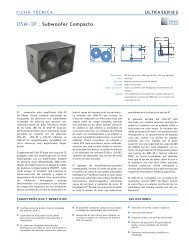
Mains circuit<br />
breakers<br />
High Limit (red)<br />
Low Limit (red)<br />
Power LED (green/red)<br />
Input polarity switch<br />
Signal input and<br />
loop connectors<br />
Remote Monitoring<br />
System panel<br />
(if RMS is installed)<br />
<strong>CQ</strong><br />
HI Limit<br />
LO Limit<br />
Active / Speaker Fault<br />
Input Polarity<br />
PUSH<br />
2 +<br />
10K Ω<br />
3 +<br />
Balanced<br />
1<br />
ESD<br />
220K Ω<br />
2<br />
Case<br />
Earth / Chassis<br />
3<br />
30.0"<br />
1 1 2<br />
3<br />
Input<br />
PUSH<br />
R E - C I R K -I T<br />
PUSH<br />
R E - C I R K -I T<br />
Loop<br />
Contents<br />
Controls and Connectors<br />
Service<br />
Rear User Panel shown with the optional<br />
Remote Monitoring System (RMS) panel<br />
Dimensions<br />
All units in inches<br />
Complete Systems .............................................. 8<br />
Verifying Polarity ............................................... 10<br />
Coverage Angles and Polar Plots..................... 11<br />
Array Design ...................................................... 14<br />
Safety Summary................................................ 15<br />
Specifications .................................................... 16<br />
2<br />
PUSH<br />
3<br />
21.0"<br />
1 1 2<br />
3<br />
Input<br />
PUSH<br />
R E - C I R K -I T<br />
PUSH<br />
R E - C I R K -I T<br />
Loop<br />
Service<br />
Wink<br />
Reset<br />
Activity<br />
Network<br />
Remote Monitor System<br />
!<br />
WARNINGS:<br />
THIS PRODUCT M<br />
This surface may reach high t<br />
To ensure proper operation, allow<br />
clearance from this surface and a<br />
To reduce the risk of electric sho<br />
No operator serviceable parts ins<br />
Refer servicing to qualified perso<br />
To reduce the risk of fire or elect<br />
do not expose this appliance to r<br />
ATENCIÓN: ACCESO INTER<br />
AUTORIZADO A PERSONAL T<br />
ACHTUNG: GEHÄUSE NICH<br />
UND REPARATUR NUR DURC<br />
ATTENTION: ENTRETIEN E<br />
INTERNES NE SONT AUTORIU<br />
PERSONNEL TECHNIQUE QUA<br />
UK WARNING: THIS APPA<br />
NO OPERATOR SERVICEABLE P<br />
REFER SERVICING TO QUALIFIE<br />
Auto-Voltage Selec<br />
10A RMS<br />
20A Peak<br />
88-127V ~<br />
50-60Hz<br />
700W RMS MAX<br />
Operational voltage<br />
Turn on 80V~ Tu<br />
Turn on 160V~ Tu<br />
European Rear User Panel<br />
with IEC 309 connector<br />
Front Side Top<br />
2.0"<br />
20.50"<br />
21.0"<br />
9.55"<br />
2.0"<br />
20.5"<br />
14.26"<br />
Wink<br />
Reset<br />
Activity<br />
Network<br />
Remote Monitoring System<br />
!<br />
WARNINGS:<br />
THIS PRODUCT MUST BE GROUNDED<br />
This surface may reach high temperatures while in use.<br />
To ensure proper operation, allow at least 6 inches<br />
clearance from this surface and adequate ventilation.<br />
To reduce the risk of electric shock do not remove cover.<br />
No operator serviceable parts inside.<br />
Refer servicing to qualified personnel.<br />
To reduce the risk of fire or electric shock<br />
do not expose this appliance to rain or moisture.<br />
ATENCIÓN: ACCESO INTERNO SOLO<br />
AUTORIZADO A PERSONAL TÉCNICO CALIFICADO<br />
ACHTUNG: GEHÄUSE NICHT ÖFFNEN WARTUNG<br />
UND REPARATUR NUR DURCH ELEKTROFACHKRÄFTE<br />
ATTENTION: ENTRETIEN ET REPARATIONS<br />
INTERNES NE SONT AUTORISEES QU'AU<br />
PERSONNEL TECHNIQUE QUALIFIÉ<br />
UK WARNING: THIS APPARATUS MUST BE EARTHED.<br />
NO OPERATOR SERVICEABLE PARTS INSIDE.<br />
REFER SERVICING TO QUALIFIED PERSONNEL<br />
Auto-Voltage Select<br />
95-125V ~ 208-235V~<br />
50-60Hz<br />
50-60Hz<br />
1400W RMS MAX 1400W RMS MAX<br />
<strong>Meyer</strong> <strong>Sound</strong>, Berkeley, CA. USA<br />
Mains AC inlet<br />
Tie-wrap anchor<br />
15.25"<br />
9.55"<br />
<strong>Meyer</strong> <strong>Sound</strong>, Be<br />
13.55"<br />
3
AC Power<br />
The AC voltage operating ranges for the <strong>CQ</strong> <strong>Series</strong> are<br />
85–134 V and 165–264 V, at 50 or 60 Hz. The <strong>CQ</strong> <strong>Series</strong><br />
performs surge suppression for high voltage transients<br />
and can safely withstand voltages up to 275 VAC.<br />
4<br />
Continuous voltages above 275 VAC may<br />
damage the unit!<br />
The Intelligent AC power supply protects the drivers<br />
and amplifier components when an AC source is applied<br />
to the <strong>CQ</strong> by<br />
• auto-selecting the voltage;<br />
• performing surge suppression and minimizing<br />
inrush current;<br />
• filtering EMI.<br />
After three seconds, the main power supply is slowly<br />
ramped on. The <strong>CQ</strong> <strong>Series</strong> uses a NEMA L6-20P or<br />
IEC 309 male power inlet and satisfies UL, CSA, and<br />
EC safety standards.<br />
Use the following AC cable wiring diagram to create<br />
international or special-purpose power connectors:<br />
blue =<br />
neutral<br />
yellow/green =<br />
earth ground<br />
(chassis)<br />
AC cable color code<br />
brown = hot<br />
If the colors referred to in the diagram don't correspond<br />
to the terminals in your plug, use the following<br />
guidelines:<br />
• Connect the blue wire to the terminal marked<br />
with an N or colored black.<br />
• Connect the brown wire to the terminal marked<br />
with an L or colored red.<br />
• Connect the green and yellow wire to the<br />
terminal marked with an E (or ) or colored<br />
green (or green and yellow).<br />
Power Requirements<br />
The <strong>CQ</strong> presents a dynamic load to the AC mains which<br />
causes the amount of current to fluctuate between quiet<br />
and loud operating levels. Since different types of<br />
cables and circuit breakers heat up at varying rates, it<br />
is essential to understand the types of current ratings<br />
and how they correspond to circuit breaker and cable<br />
specifications.<br />
The maximum continuous RMS current is the maximum<br />
RMS current in a period of at least 10 seconds. It is<br />
used to calculate the temperature increase in cables,<br />
which is used to select cables that conform to electrical<br />
code standards. It is also used to select the rating for<br />
slow-reacting thermal breakers.<br />
The maximum burst RMS current is the maximum<br />
RMS current in a period of approximately 1 second. It<br />
is used to select the rating for most magnetic breakers.<br />
The maximum peak current during burst is used to<br />
select the rating for fast-reacting magnetic breakers<br />
and to calculate the peak voltage drop in long AC<br />
cables according to the formula<br />
Vpk drop = Ipk x Total Cable Resistance<br />
Use the table below as a guide to select cables and<br />
circuit breakers with appropriate ratings for your<br />
operating voltage.<br />
<strong>CQ</strong><br />
S<br />
eries<br />
Current<br />
Max. Continuous<br />
RMS<br />
A<br />
R<br />
atings<br />
115 V 230 V 100<br />
V<br />
8 RMS<br />
Max. Burst<br />
RMS<br />
5 A<br />
1 RMS<br />
Max. Peak<br />
During<br />
Burst<br />
2 A<br />
4 ARMS<br />
8 ARMS<br />
10 ARMS<br />
18 ARMS<br />
2 11 A 25 A<br />
PEAK<br />
PEAK<br />
PEAK<br />
The minimum electrical service amperage required by<br />
a system of <strong>CQ</strong>s is the sum of the maximum continuous<br />
RMS current for each speaker. We recommend allowing<br />
an additional 30% above the minimum amperage to<br />
prevent peak voltage drops at the service entry.
Safety Issues<br />
Pay close attention to these important electrical and<br />
safety issues.<br />
Use a power cord adapter to drive the <strong>CQ</strong> from a<br />
standard 3-prong outlet (NEMA 5-15R; 125 V max).<br />
earth<br />
ground<br />
chassis<br />
ground<br />
The <strong>CQ</strong> requires a grounded outlet. Always use<br />
a grounding adapter when connecting to<br />
ungrounded outlets.<br />
Do not use a ground-lifting adapter or cut the AC<br />
cable ground pin.<br />
Keep all liquids away from the <strong>CQ</strong> to avoid hazards<br />
from electrical shock.<br />
Do not operate the unit if the power cables are frayed<br />
or broken.<br />
Tie-wrap anchors on the amplifier chassis provide<br />
strain relief for the power and signal cables. Insert the<br />
plastic tie-wraps through the anchors and wrap them<br />
around the cables.<br />
Audio Input<br />
The <strong>CQ</strong> presents a 10 kΩ input impedance to a three-pin<br />
XLR connector wired with the following convention:<br />
Pin 1 — 220 kΩ to chassis and earth ground (ESD clamped)<br />
Pin 2 —<br />
Pin 3 —<br />
Signal<br />
Signal<br />
Differential Inputs<br />
Case — Earth (AC) ground and chassis<br />
Pins 2 and 3 carry the input as a differential signal;<br />
their polarity can be reversed with the input polarity<br />
switch on the user panel. If the switch is in the up<br />
position, pin 2 is hot relative to pin 3, resulting in a<br />
positive pressure wave when a positive signal is applied<br />
to pin 2. Use standard audio cables with XLR connectors<br />
for balanced signal sources.<br />
Shorting an input connector pin to the case<br />
can form a ground loop and cause hum.<br />
A single source can drive multiple <strong>CQ</strong>s with a paralleled<br />
input loop, creating an unbuffered hardwired loop<br />
connection. Make certain that the source equipment<br />
can drive the total load impedance presented by the<br />
paralleled input circuit. For example, since the input<br />
impedance of a single <strong>CQ</strong> is 10 kΩ, cascading 20 <strong>CQ</strong>s<br />
produces a balanced input impedance of 500 Ω. If a<br />
150 Ω source is used, the 500 Ω load results in a 2.28 dB<br />
loss.<br />
Troubleshooting<br />
If the Active lamp does not light after connection to an<br />
AC source for three seconds, the problem is probably in<br />
the power supply. In the unlikely case that the circuit<br />
breakers trip (the white center buttons pop out), the<br />
amplifier or power supply may be malfunctioning.<br />
Do not reset the breakers! Contact <strong>Meyer</strong> <strong>Sound</strong> for repair<br />
information.<br />
If abnormal noise (hum, hiss, popping) is produced<br />
from the loudspeaker, disconnect the audio source<br />
from the speaker. If the noise stops, then the problem<br />
is not within the loudspeaker; check your audio and<br />
AC power sources.<br />
If problems persist, contact <strong>Meyer</strong> <strong>Sound</strong>. If repairs<br />
are necessary, the <strong>CQ</strong>’s modular components are easy<br />
to remove and ship.<br />
5
Limiting and Protection<br />
Circuitry<br />
TruPower Limiting System<br />
Conventional limiters assume that the resistance of a<br />
speaker remains constant and set the limiting threshold<br />
by measuring voltage only. This method is inaccurate<br />
because the speaker’s resistance changes in response<br />
to the frequency content of the source material and<br />
thermal variations in the speaker’s voice coil and magnet.<br />
Conventional limiters begin limiting prematurely,<br />
which under-utilizes system headroom and deprives<br />
the speaker of its full dynamic range.<br />
The TruPower Limiting (TPL) system accounts for<br />
varying speaker impedance by measuring current, in<br />
addition to voltage, to compute the power dissipation<br />
and voice coil temperature. TPL<br />
• allows the speaker to deliver its highest SPL<br />
across its entire frequency range during limiting;<br />
• eliminates long-term power compression when<br />
operated at high levels for extended periods;<br />
• protects the drivers and extends the lifetime of<br />
amplifier and driver components.<br />
Hi Limit and Lo Limit LEDs on the user panel indicate<br />
TPL activity for the high and low frequency drivers,<br />
respectively. The limiters for each driver function<br />
independently and do not affect the signal when the<br />
LEDs are inactive. Limiting begins when the driver<br />
temperature exceeds the maximum safe level and<br />
ceases when the temperature returns to normal.<br />
The <strong>CQ</strong> performs within its acoustical specifications<br />
and operates at a normal temperature if the limit LEDs<br />
are on for no longer than two seconds, and off for at<br />
least one second. If the LEDs remain on for longer<br />
than three seconds, the <strong>CQ</strong> is hard limiting with the<br />
following negative consequences:<br />
• <strong>Inc</strong>reasing the input level will not increase the<br />
volume.<br />
• The system distorts due to clipping and<br />
nonlinear driver operation.<br />
• Unequal limiting between the low and high<br />
frequency drivers alters the frequency response.<br />
• Driver and amplifier components are subjected<br />
to maximum heat, which shortens their life span.<br />
6<br />
Troubleshooting with TPL<br />
The TPL LEDs can indicate serious driver problems, if<br />
interpreted correctly. If one <strong>CQ</strong> in a system exhibits<br />
substantially more TPL activity than others receiving the<br />
same audio signal, then the driver corresponding to<br />
the excessively active LED may have a short circuit. This<br />
is a potentially dangerous condition for the electronics;<br />
shut the <strong>CQ</strong> down immediately.<br />
The TPL circuit does not activate if there is no power<br />
dissipation in the driver, regardless of the input signal<br />
level. Therefore, if all <strong>CQ</strong>s in a system receiving the same<br />
audio signal exhibit TPL activity except one, then that<br />
unit may have an open voice coil; disconnect it and<br />
contact <strong>Meyer</strong> <strong>Sound</strong> for repair information.<br />
TPL can indicate an imbalance in a configuration of<br />
speakers by functioning like a spectrum analyzer. If the<br />
speakers in a subwoofer, mid-bass, or mid-hi subsystem<br />
begin to limit before reaching the required operating<br />
level for the entire system, then that subsystem needs to<br />
be supplemented with additional speakers.<br />
NOTE: Although the TPL limiters exhibit smooth sonic<br />
characteristics, we do not recommend using them for<br />
intentional compression effects. Use an outboard<br />
compressor/limiter to compress a mixed signal.
Fans and Cooling System<br />
The <strong>CQ</strong> uses a forced-air cooling system with two fans<br />
to prevent the amplifiers from overheating. A variablespeed<br />
primary fan runs continuously with an inaudible<br />
operating noise of 22 dBA at 1 m at its slowest speed.<br />
The speed of the primary fan begins increasing when<br />
the temperature of the heatsinks reaches 42°C. The<br />
fan reaches full speed at 62°C and is barely audible near<br />
the cabinet, even without an audio signal.<br />
In the unusual event that the temperature reaches<br />
74°C, the secondary fan turns on and is clearly audible.<br />
The secondary fan turns on in response to<br />
• primary fan failure (check its status immediately);<br />
• high source levels for a prolonged period in hot<br />
temperatures or direct sunlight;<br />
• driver failure.<br />
The secondary fan turns off when the temperature<br />
decreases to 68°C.<br />
In the highly unlikely event that the secondary fan<br />
does not keep the temperature below 85°C, the <strong>CQ</strong><br />
automatically shuts down until AC power is removed<br />
and reapplied. If the <strong>CQ</strong> shuts down again after cooling<br />
and reapplying AC power, contact <strong>Meyer</strong> <strong>Sound</strong> for<br />
repair information.<br />
The fans draw air in through ducts on the front of the<br />
cabinet, over the heatsinks, and out the rear of the<br />
cabinet. Since dust does not accumulate in the amplifier<br />
circuitry, its life span is increased significantly. Make<br />
sure that the air ducts are clear and that there is at<br />
least 6 inches clearance for exhaust behind the cabinet.<br />
air<br />
cooling<br />
fans<br />
heatsinks<br />
power<br />
supply<br />
A foam insert filter, in combination with the entire<br />
front grill surface, acts as an air filter for the cooling<br />
system. Despite the filtering, extensive use or a dusty<br />
operating environment can allow dust to accumulate<br />
along the path of the airflow, preventing normal cooling.<br />
We recommend periodically removing the grill, filter,<br />
and amplifier module and using compressed air to<br />
clear dust from the grill, filter, fans, and heatsinks.<br />
Rigging<br />
The maximum recommended load for a <strong>CQ</strong> with aircraft<br />
pan fittings is 500 lb (228kg). This working load<br />
is one-fifth the cabinet’s breaking strength. The <strong>CQ</strong><br />
has two rigging brackets on both the top and bottom<br />
of the cabinet; each bracket is capable of supporting<br />
the full working load of the cabinet.<br />
!<br />
rigging brackets<br />
(two on top, two on bottom)<br />
Handles are for carrying only.<br />
Do not use them for rigging!<br />
There are four types of interchangeable rigging brackets,<br />
each fastened by six Phillips screws:<br />
• aircraft pan fittings (ring and stud)<br />
• 3 /8”-16 nut plates<br />
• M-10 x 1.5 metric nut plates<br />
• blank plates (if no rigging brackets are requested)<br />
NOTE: Units with nut plates are rated for the weight of<br />
one cabinet only.<br />
Rigging load ratings assume a straight tensile pull and<br />
that the cabinet is in new condition with aircraft pan<br />
fittings. If these conditions are not met, the load ratings<br />
can be reduced significantly. Load ratings can also be<br />
reduced by age, wear, and damage. It is important to<br />
inspect the rigging hardware regularly and replace<br />
worn or damaged components immediately.<br />
The standard model should not be installed outdoors<br />
without weather protection. The cabinet, exposed<br />
electronic circuitry, and drivers can all receive weather<br />
protection treatment that allows the unit to be used<br />
safely in wet conditions. Contact <strong>Meyer</strong> <strong>Sound</strong> for<br />
information about weather-protected units.<br />
NOTE: All <strong>Meyer</strong> <strong>Sound</strong> products must be used in<br />
accordance with local, state, federal, and industry<br />
regulations. It is the owner’s and/or user’s responsibility<br />
to evaluate the reliability of any rigging method for<br />
their application. Rigging should be done only by<br />
experienced professionals.<br />
7
Complete Systems<br />
Speaker Placement and Polarity<br />
The cabinets in the following example configurations<br />
are in a close-proximity coplanar orientation, unless<br />
otherwise stated. Placing the mid-hi speaker more<br />
than 5 feet from the subwoofer may require setting the<br />
speakers to opposite polarities to compensate for the<br />
propagation delay between them.<br />
In a coplanar orientation, externally amplified <strong>Meyer</strong><br />
subwoofers require the opposite polarity setting to<br />
all <strong>Meyer</strong> self-powered speakers.<br />
We recommend using the <strong>Meyer</strong> SIM® System II<br />
<strong>Sound</strong> Analyzer and CP-10 Parametric Equalizer to<br />
• assist the process of configuring and placing<br />
speakers in a system;<br />
• measure propagation delays to set the correct<br />
polarity between speakers;<br />
• measure and equalize variations in frequency<br />
response caused by the acoustical environment<br />
and the placement and interaction of speakers.<br />
Contact <strong>Meyer</strong> <strong>Sound</strong> for assistance with your<br />
application.<br />
The LD-1A Line Driver<br />
We recommend using the <strong>Meyer</strong> LD-1A Line Driver<br />
to integrate different types of <strong>Meyer</strong> self-powered<br />
speakers into a full-range system. The LD-1A maintains<br />
signal integrity for long cable paths, has two channels<br />
equipped to control a main system, and six auxiliary<br />
channels for down-fill, front-fill, and delay systems. The<br />
LD-1A provides these useful functions:<br />
• The Lo Cut switch activates a high-pass filter<br />
(160 Hz, –12 dB/oct, Q = 0.8) that performs a<br />
crossover function for the Mid-Hi output.<br />
• The Array EQ switch activates a filter (6 dB cut<br />
at 220 Hz, 0.6 octave bandwidth) to equalize<br />
groups of 3 to 5 horizontally arrayed MSL-4s.<br />
• The DS-2 & Sub Crossover switch activates a<br />
crossover network that sends frequencies below<br />
80 Hz to the Sub output, and above 80 Hz to the<br />
DS-2 output. With the switch out, a full-range<br />
signal is sent to the DS-2 and Sub outputs.<br />
• The DS-2 φ and Sub φ switches toggle the polarity<br />
for the DS-2 and Sub outputs.<br />
• The Mid-Hi, DS-2, and Sub outputs each have<br />
their own gain control and mute switch.<br />
8<br />
<strong>Meyer</strong> Speaker Types<br />
The following <strong>Meyer</strong> speakers will be mentioned in<br />
the example applications.<br />
MSL-4: Self-powered mid-hi speaker<br />
DS-2P: Self-powered mid-bass speaker<br />
650-P, PSW-2,<br />
PSW-4: Self-powered subwoofers<br />
650-R2, MSW-2,<br />
USW-1: Externally amplified subwoofers<br />
The self-powered speakers listed above have a loop<br />
connection to send the input signal to another speaker.<br />
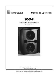
<strong>CQ</strong> and 650-P<br />
The <strong>CQ</strong> is particularly well matched with the 650-P and<br />
also performs efficiently with the PSW-2 and PSW-4.<br />
Due to the overlap in frequency response between<br />
the <strong>CQ</strong> and the subwoofer, the system frequency<br />
response contains a rise in the range 40–120 Hz. It is<br />
important to emphasize that the speakers are in phase<br />
in this region. The rise can be corrected using the <strong>Meyer</strong><br />
CP-10 Parametric Equalizer, if desired.<br />
CP-10 EQ<br />
(1 Channel)<br />
input<br />
loop<br />
<strong>CQ</strong>-1 or<br />
<strong>CQ</strong>-2<br />
650-P<br />
Set the <strong>CQ</strong> and 650-P to the same polarity.<br />
<strong>CQ</strong> and 650-R2<br />
Although it is preferable to use the <strong>CQ</strong> in a completely<br />
self-powered system, excellent results can still be<br />
achieved using the 650-R2, USW-1, and MSW-2.<br />
CP-10 EQ<br />
(1 Channel)<br />
B-2EX<br />
CEU<br />
Amplifier<br />
input<br />
loop<br />
Set the <strong>CQ</strong> and the 650-R2‘s amplifier to opposite<br />
polarities.<br />
<strong>CQ</strong>-1 or<br />
<strong>CQ</strong>-2<br />
650-R2<br />
subwoofer
LD-1A with <strong>CQ</strong> and 650-P<br />
Activating the Lo Cut filter on the LD-1A for the Mid-Hi<br />
output also eliminates the low frequency rise caused<br />
by the overlap between the <strong>CQ</strong> and 650-P. Although a<br />
typical <strong>CQ</strong> : 650-P ratio is 2:1, separate Sub and Mid-Hi<br />
level controls on the LD-1A allow the ratio to vary<br />
while maintaining control of the spectral balance of<br />
the system.<br />
Mid-hi<br />
LD-1A<br />
Line Driver<br />
Sub<br />
<strong>CQ</strong>-1 or<br />
<strong>CQ</strong>-2<br />
650-P<br />
Set the <strong>CQ</strong> and 650-P to the same polarity.<br />
LD-1A with Flown MSL-4, DS-2P, and <strong>CQ</strong>;<br />
650-P on the Floor<br />
This example shows the LD-1A integrating a complete<br />
system of speakers appropriate for a large venue.<br />
Although channels 1, 3, and 5 constitute half of a<br />
complete system, channels 2, 4, and 6 can be used<br />
with identical connections to create the other half of<br />
the system. The MSL-4 mid-hi, DS-2P mid-bass, and<br />
<strong>CQ</strong> down-fill speakers are flown; the 650-P subwoofers<br />
are on the floor.<br />
The Mid-Hi and CH 3 outputs drive the inner three<br />
and outer two speakers, respectively, of the MSL-4<br />
array. These two outputs apply appropriate levels for<br />
speakers directed at audience locations at different<br />
distances from the main system. The diagram shows the<br />
additional mid-hi output created by connecting the<br />
CH 1 Loop to the CH 3 input. Using a Y-connection at<br />
the CH 1 input, as shown for the down-fills, accomplishes<br />
the same signal routing.<br />
The Lo Cut and Array EQ switches for the Mid-Hi and<br />
CH 3 outputs should be in. The Lo Cut filter eliminates<br />
the rise caused by the overlap between the MSL-4 and<br />
DS-2P/650-P systems. The Array EQ filter minimizes<br />
the low-mid rise caused by the MSL-4 array.<br />
The DS-2 and Sub outputs drive the DS-2P and 650-P<br />
systems with the DS-2 & Crossover switch in. Set the<br />
MSL-4 and DS-2P to the same polarity. The polarity of<br />
the 650-P depends on the displacement from the flown<br />
system.<br />
CH 5 controls the <strong>CQ</strong> down-fill system. Since the main<br />
system is normally set to a higher volume than the<br />
down-fill system to project farther into the venue, the<br />
main system is audible in the down-fill’s coverage<br />
area. To insure that the speakers combine properly in<br />
the overlapping coverage area:<br />
• Set the <strong>CQ</strong> to the opposite polarity to the MSL-4<br />
and DS-2P to phase align the mid-hi frequencies and<br />
minimize the MSL-4’s low frequency down-lobe.<br />
• Use the CH 5 Lo Cut filter to eliminate the low<br />
frequency rise caused by the overlap with the<br />
650-P/DS-2P systems.<br />
• Delay the down-fill to compensate for the<br />
propagation delay between the down-fill and<br />
main systems in the intersecting coverage area.<br />
(This is highly recommended, but not required.)<br />
We recommend using the <strong>Meyer</strong> SIM System II <strong>Sound</strong><br />
Analyzer and CP-10 Parametric Equalizer to optimize this<br />
configuration.<br />
Delay<br />
CP-10 EQ<br />
CP-10 EQ<br />
LD-1A<br />
CH 1<br />
Input Mid-Hi<br />
Output<br />
Loop DS-2<br />
Output<br />
Sub<br />
Output<br />
Input Output<br />
CH 3<br />
Input Output<br />
CH 5<br />
MSL-4 Mid-Hi<br />
DS-2P Mid-Bass<br />
<strong>CQ</strong> Down-fills<br />
650-P Subwoofers<br />
Set the MSL-4 and DS-2P to the same polarity; reverse<br />
the polarity for the <strong>CQ</strong>. The polarity for the 650-P depends<br />
on the displacement from the flown system.<br />
9
Verifying Polarity<br />
<strong>Inc</strong>orrect driver polarity impairs system performance<br />
and may damage the drivers. All <strong>Meyer</strong> <strong>Sound</strong><br />
loudspeakers are shipped with the drivers in correct<br />
alignment. However, if the driver or circuit wiring has<br />
been removed or disassembled in any loudspeaker in<br />
a system for any reason, check the polarity between<br />
adjacent loudspeakers and between drivers in the<br />
same cabinet.<br />
Polarity Between Adjacent Loudspeakers<br />
Use the following test procedure to verify the polarity<br />
between adjacent loudspeakers of the same type:<br />
1. Position two loudspeakers adjacent to each other.<br />
2. Place a measurement microphone six ft from the<br />
speakers on the axis between them.<br />
3. Connect a signal source to one speaker and note<br />
the frequency response and overall level.<br />
4. Apply the same signal to the second speaker with<br />
the first speaker still connected.<br />
Correct polarity causes<br />
acoustic addition<br />
10<br />
Top view of adjacent speakers with<br />
measurement microphone<br />
Opposite polarity causes<br />
acoustic cancellation<br />
The polarity is correct if the frequency response<br />
remains constant with a significant increase in<br />
amplitude. Broadband cancellation (decreased overall<br />
level) indicates polarity reversal.<br />
Driver Polarity in the Same Loudspeaker<br />
Use the following test procedure to verify polarity<br />
between drivers in the same loudspeaker:<br />
1. Place a monitoring microphone three ft from the<br />
front of the loudspeaker at the midway point<br />
between the low and high frequency drivers.<br />
2. Connect a signal source to the loudspeaker and<br />
note the frequency response.<br />
! Since polarity reversal causes excessive driver<br />
excursion at high source levels, use moderate levels<br />
when conducting this test.<br />
Drivers with correct<br />
polarity cause acoustic<br />
addition<br />
Drivers with reversed<br />
polarity cause acoustic<br />
cancellation<br />
The polarity is correct if the frequency response is smooth<br />
through the crossover region (±4 dB 600 Hz – 1 kHz).<br />
Severe cancellation in the crossover region indicates<br />
polarity reversal.
Coverage Angles and<br />
Polar Plots<br />
Coverage Angles<br />
The coverage angles for the <strong>CQ</strong> <strong>Series</strong> over a wide<br />
frequency range are summarized in the following table:<br />
<strong>CQ</strong><br />
<strong>Series</strong><br />
Coverage<br />
Angles<br />
1 horizontal vertical<br />
<strong>CQ</strong>-1 ( – 6 dB<br />
points)<br />
8 0°<br />
4 0°<br />
<strong>CQ</strong>-1 ( – 10<br />
dB<br />
points)<br />
1 00°<br />
5 0°<br />
<strong>CQ</strong>-2 ( – 6 dB<br />
points)<br />
5 0°<br />
4 0°<br />
<strong>CQ</strong>-2 ( – 10<br />
dB<br />
points)<br />
6 0°<br />
5 0°<br />
1. <strong>CQ</strong>-1: 500 Hz–16 kHz; <strong>CQ</strong>-2: 800 Hz–12 kHz<br />
2. <strong>CQ</strong>-1 and <strong>CQ</strong>-2: 1.5–12 kHz<br />
The –6 dB points denote the angle at which the measured<br />
SPL has decreased to half its on-axis value. The –10 dB<br />
points represent the angle at which the perceived SPL<br />
has decreased to half its on-axis value.<br />
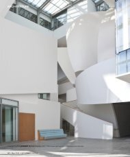
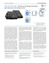
Polar Plots<br />
The data for the <strong>CQ</strong> <strong>Series</strong> polar patterns was measured<br />
in <strong>Meyer</strong> <strong>Sound</strong>’s anechoic chamber (photo at right)<br />
with the SIM System II <strong>Sound</strong> Analyzer in dB SPL at a<br />
distance of 14 ft, using angular and frequency resolutions<br />
of 1° and 1 ⁄24 octave, respectively. The polar plots on<br />
the following pages have been smoothed to angular<br />
and frequency resolutions of 2° and 1 octave, and<br />
normalized to 0 dB on-axis. Each polar pattern shows<br />
the response of a 1 octave band centered at the frequency<br />
indicated on the plot; there are no gaps in the data<br />
from 125 Hz to 16 kHz.<br />
The polar patterns reveal that the <strong>CQ</strong>-1 has a wider<br />
horizontal coverage pattern than the <strong>CQ</strong>-2 and that<br />
their vertical coverage is virtually identical. The uniform<br />
beam width that distinguishes the <strong>CQ</strong> <strong>Series</strong> is evident<br />
in their polar patterns in the horn’s range (1–16 kHz);<br />
note the lack of side or back lobes.<br />
2<br />
The table below lists the maximum on-axis peak dB SPL<br />
per octave measured at 1 m for the <strong>CQ</strong>-1 and <strong>CQ</strong>-2.<br />
Maximum<br />
Peak<br />
dB<br />
SPL<br />
Frequency <strong>CQ</strong>-1 <strong>CQ</strong>-2<br />
125 Hz<br />
127127 250 Hz<br />
130 130<br />
500 Hz<br />
130 130<br />
1 kHz<br />
132 139<br />
2 kHz<br />
136 139<br />
4 kHz<br />
136 139<br />
8 kHz<br />
132 134<br />
16 kHz<br />
122 124<br />
<strong>Meyer</strong> <strong>Sound</strong>’s anechoic chamber<br />
11
vertical<br />
<strong>CQ</strong>-1: 125 Hz<br />
Inner plot is vertical unless<br />
otherwise indicated.<br />
<strong>CQ</strong>-1: 250 Hz<br />
<strong>CQ</strong>-1: 500 Hz<br />
<strong>CQ</strong>-1: 2 kHz<br />
12<br />
<strong>CQ</strong>-1 Polar Plots<br />
vertical<br />
vertical<br />
<strong>CQ</strong>-1: 1 kHz<br />
<strong>CQ</strong>-1: 4 kHz<br />
<strong>CQ</strong>-1: 8 kHz <strong>CQ</strong>-1: 16 kHz
<strong>CQ</strong>-2: 125 Hz<br />
<strong>CQ</strong>-2: 500 Hz<br />
<strong>CQ</strong>-2: 2 kHz<br />
<strong>CQ</strong>-2 Polar Plots<br />
Inner plot is vertical unless<br />
otherwise indicated.<br />
vertical<br />
vertical<br />
<strong>CQ</strong>-2: 250 Hz<br />
vertical<br />
<strong>CQ</strong>-2: 1 kHz<br />
<strong>CQ</strong>-2: 4 kHz<br />
<strong>CQ</strong>-2: 8 kHz <strong>CQ</strong>-2: 16 kHz<br />
13
Array Design<br />
Creating an effective array with the <strong>CQ</strong> requires a<br />
precise understanding of how to combine the coverage<br />
area and SPL of the individual speaker with those of<br />
adjacent speakers. Array design is a trade-off between<br />
increasing on-axis power and creating smooth transitions<br />
between the coverage areas of adjacent speakers.<br />
As the splay angle (the angle between adjacent cabinet<br />
faces) decreases below the coverage angle of the<br />
individual speaker, the on-axis power increases, but<br />
the coverage overlap between adjacent speakers causes<br />
comb filtering and other frequency response variations.<br />
As the splay angle increases toward the coverage<br />
angle, the on-axis power decreases, but the variations<br />
in frequency response diminish. As the splay angle<br />
increases beyond the coverage angle, noticeable gaps<br />
begin to form in the array’s coverage area.<br />
NOTE: The trapezoidal shape of the <strong>CQ</strong> does not<br />
represent the horizontal coverage area of the speaker<br />
or the intended splay angle for horizontal arrays. The<br />
20° angle of the <strong>CQ</strong> enclosure is narrower than the<br />
minimum recommended splay angle.<br />
14<br />
<strong>CQ</strong>-1 Array Coverage and Maximum SPL Chart<br />
<strong>CQ</strong>-2 Array Coverage and Maximum SPL Chart<br />
A series of outdoor tests was conducted at <strong>Meyer</strong> <strong>Sound</strong><br />
to determine the coverage angle and on-axis SPL for<br />
arrays with one and two horizontal rows of up to four<br />
elements each, at numerous splay angles. The measurements<br />
were conducted at a distance of 8 m with half-space<br />
loading; on-axis SPL values were interpolated from<br />
8 m to 1 m. The coverage angle for the array is the result<br />
of averaging the –6 dB points from 125 Hz to 8 kHz.<br />
The horizontal splay angles in the tables below represent<br />
the optimal configurations for narrow and wide coverage<br />
areas; note the different angles for the <strong>CQ</strong>-1 and <strong>CQ</strong>-2.<br />
The vertical angles represent the optimal narrow (15°),<br />
middle (30°), and wide (40°) orientations for both the<br />
<strong>CQ</strong>-1 and <strong>CQ</strong>-2. The 2@0° LT denotes the long throw<br />
configuration: the two horns are coupled directly<br />
together (top speaker upside down/bottom speaker<br />
upright) to form a single narrow horn.<br />
The following tables show the SPL and coverage areas<br />
that result from grouping the <strong>CQ</strong>-1 and <strong>CQ</strong>-2 in arrays<br />
of up to four units horizontally and two rows vertically.<br />
All splay angles refer to the angle between cabinet<br />
centers. If this information does not address your<br />
application requirements, contact <strong>Meyer</strong> <strong>Sound</strong> to<br />
obtain additional information on array design.<br />
Number of Horizontal<br />
<strong>CQ</strong> units @ Angle 1 2 @ 50° 2 @ 70° 3 @ 50° 3 @ 70° 4 @ 50° 4 @ 70°<br />
Coverage Max Peak Coverage Max Peak Coverage Max Peak Coverage Max Peak Coverage Max Peak Coverage Max Peak Coverage Max Peak<br />
H V dB SPL H V dB SPL H V dB SPL H V dB SPL H V dB SPL H V dB SPL H V dB SPL<br />
Number of Vertical<br />
Rows of <strong>CQ</strong> @ Angle<br />
1 80° 40° 136 100° 40° 140 150° 40° 139 170° 40° 140 220° 40° 138 220° 40° 141 300° 40° 139<br />
2 @ 0° (LT) 80° 20° 142 100° 20° 146 150° 20° 145 170° 20° 146 220° 20° 144 220° 20° 147 300° 20° 145<br />
2 @ 15° 80° 45° 140 100° 45° 144 150° 45° 143 170° 45° 144 220° 45° 142 220° 45° 145 300° 45° 143<br />
2 @ 30° 80° 60° 139 100° 60° 143 150° 60° 142 170° 60° 143 220° 60° 141 220° 60° 144 300° 60° 142<br />
2 @ 40° 80° 80° 138 100° 80° 142 150° 80° 141 170° 80° 142 220° 80° 140 220° 80° 143 300° 80° 141<br />
Number of Horizontal<br />
<strong>CQ</strong> units @ Angle 1 2 @ 30° 2 @ 40° 3 @ 30° 3 @ 40° 4 @ 30° 4 @ 40°<br />
Coverage Max Peak Coverage Max Peak Coverage Max Peak Coverage Max Peak Coverage Max Peak Coverage Max Peak Coverage Max Peak<br />
H V dB SPL H V dB SPL H V dB SPL H V dB SPL H V dB SPL H V dB SPL H V dB SPL<br />
Number of Vertical<br />
Rows of <strong>CQ</strong> @ Angle<br />
1 50° 40° 139 70° 40° 143 90° 40° 142 100° 40° 144 130° 40° 144 130° 40° 145 170° 40° 144<br />
2 @ 0° (LT) 50° 20° 145 70° 20° 149 90° 20° 148 100° 20° 150 130° 20° 150 130° 20° 151 170° 20° 150<br />
2 @ 15° 50° 45° 143 70° 45° 147 90° 45° 146 100° 45° 148 130° 45° 148 130° 45° 149 170° 45° 148<br />
2 @ 30° 50° 60° 142 70° 60° 146 90° 60° 145 100° 60° 147 130° 60° 147 130° 60° 148 170° 60° 147<br />
2 @ 40° 50° 80° 141 70° 80° 145 90° 80° 144 100° 80° 146 130° 80° 146 130° 80° 147 170° 80° 146
English Français<br />
• To reduce the risk of electric shock, disconnect the loudspeaker<br />
from the AC mains before installing audio cable.<br />
Reconnect the power cord only after making all signal<br />
connections.<br />
• Connect the loudspeaker to a two-pole, three wire grounding<br />
mains receptacle. The receptacle must be connected to a<br />
fuse or circuit breaker. Connection to any other type of<br />
receptacle poses a shock hazard and may violate local<br />
electrical codes.<br />
• Do not install the loudspeaker in wet or humid locations<br />
without using weather protection equipment from <strong>Meyer</strong><br />
<strong>Sound</strong>.<br />
• Do not allow water or any foreign object to get inside the<br />
loudspeaker. Do not put objects containing liquid on, or<br />
near, the unit.<br />
• To reduce the risk of overheating the loudspeaker, avoid<br />
exposing it to direct sunlight. Do not install the unit near<br />
heat emitting appliances, such as a room heater or stove.<br />
• This loudspeaker contains potentially hazardous voltages. Do<br />
not attempt to disassemble the unit. The unit contains no<br />
user serviceable parts. Repairs should be performed only by<br />
factory trained service personnel.<br />
Safety Summary<br />
Deutsch Español<br />
• Um die Gefahr eines elektrischen Schlages auf ein<br />
Minimum zu reduzieren, den Lautsprecher vom<br />
Stromnetz trennen, bevor ggf. ein Audio-<br />
Schnittstellensignalkabel angeschlossen wird. Das<br />
Netzkabel erst nach Herstellung aller<br />
Signalverbindungen wieder einstecken.<br />
• Der Lautsprecher an eine geerdete zweipolige<br />
Dreiphasen-Netzsteckdose anschließen. Die Steckdose<br />
muß mit einem geeigneten Abzweigschutz (Sicherung<br />
oder Leistungsschalter) verbunden sein. Der Anschluß<br />
der unterbrechungsfreien Stromversorgung an einen<br />
anderen Steckdosentyp kann zu Stromschlägen führen<br />
und gegen die örtlichen Vorschriften verstoßen.<br />
• Der Lautsprecher nicht an einem Ort aufstellen, an dem<br />
sie mit Wasser oder übermäßig hoher Luftfeuchtigkeit in<br />
Berührung kommen könnte.<br />
• Darauf achten, daß weder Wasser noch Fremdkörper in<br />
das Innere den Lautsprecher eindringen. Keine Objekte,<br />
die Flüssigkeit enthalten, auf oder neben die<br />
unterbrechungsfreie Stromversorgung stellen.<br />
• Um ein Überhitzen dem Lautsprecher zu verhindern,<br />
das Gerät vor direkter Sonneneinstrahlung fernhalten<br />
und nicht in der Nähe von wärmeabstrahlenden<br />
Haushaltsgeräten (z.B. Heizgerät oder Herd) aufstellen.<br />
• Im Inneren diesem Lautsprecher herrschen potentiell<br />
gefährliche Spannungen. Nicht versuchen, das Gerät zu<br />
öffnen. Es enthält keine vom Benutzer reparierbaren<br />
Teile. Reparaturen dürfen nur von ausgebildetem<br />
Kundenienstpersonal durchgeführt werden.<br />
!<br />
• Pour réduire le risque d’électrocution, débranchez la<br />
prise principale de l’haut-parleur, avant d’installer le<br />
câble d’interface allant à l’audio. Ne rebranchez le bloc<br />
d’alimentation qu’après avoir effectué toutes les<br />
connections.<br />
• Branchez l’haut-parleur dans une prise de courant à 3<br />
dérivations (deux pôles et la terre). Cette prise doit être<br />
munie d’une protection adéquate (fusible ou coupecircuit).<br />
Le branchement dans tout autre genre de prise<br />
pourrait entraîner un risque d’électrocution et peut<br />
constituer une infraction à la réglementation locale<br />
concernant les installations électriques.<br />
• Ne pas installer l’haut-parleur dans un endroit où il y a<br />
de l’eau ou une humidité excessive.<br />
• Ne pas laisser de l’eau ou tout objet pénétrer dans l’hautparleur.<br />
Ne pas placer de r´cipients contenant un liquide<br />
sur cet appareil, ni à proximité de celui-ci.<br />
• Pour éviter une surchauffe de l’haut-parleur, conservezla<br />
à l’abri du soleil. Ne pas installer à proximité<br />
d’appareils dégageant de la chaleur tels que radiateurs<br />
ou appareils de chauffage.<br />
• Ce haut-parleur contient des circuits haute tension<br />
présentant un danger. Ne jamais essayer de le démonter.<br />
Il n’y a aucun composant qui puisse être réparé par<br />
l’utilisateur. Toutes les réparations doivent être<br />
effectuées par du personnel qualifié et agréé par le<br />
constructeur.<br />
• Para reducir el riesgo de descarga eléctrica, desconecte<br />
de la red el altoparlante antes de instalar el cable de<br />
señalización de interfaz de la segnale. Vuelva a conectar<br />
el conductor flexible de alimentación solamente una vez<br />
efectuadas todas las interconexiones de señalizatción.<br />
• Conecte el altoparlante a un tomacorriente bipolar y<br />
trifilar con neutro de puesta a tierra. El tomacorriente<br />
debe estar conectado a la protección de derivación<br />
apropiada (ya sea un fusible o un disyuntor). La<br />
conexión a cualquier otro tipo de tomacorriente puede<br />
constituir peligro de descarga eléctrica y violar los<br />
códigos eléctricos locales.<br />
• No instale el altoparlante en lugares donde haya agua o<br />
humedad excesiva.<br />
• No deje que en el altoparlante entre agua ni ningún<br />
objeto extraño. No ponga objetos con líquidos encima de<br />
la unidad ni cerca de ella.<br />
• Para reducir el riesgo de sobrecalentamiento, no<br />
exponga la unidad a los rayos directos del sol ni la<br />
instale cerca de artefactos que emiten calor, como estufas<br />
o cocinas.<br />
• Este altoparlante contiene niveles de voltaje peligrosos<br />
en potencia. No intente desarmar la unidad, pues no<br />
contiene piezas que puedan ser repardas por el usuario.<br />
Las reparaciones deben efectuarse únicamente por parte<br />
del personal de mantenimiento capacitado en la fábrica.<br />
15
16<br />
Acoustical<br />
Frequency Response1 Phase Response1 Maximum Peak SPL1 Dynamic Range2 Coverage<br />
<strong>CQ</strong>-1<br />
–6 dB points<br />
–10 dB points<br />
<strong>CQ</strong>-2<br />
–6 dB points<br />
–10 dB points<br />
Transducers<br />
Low Frequency<br />
High Frequency<br />
Acoustical Crossover Point<br />
<strong>CQ</strong>-1<br />
<strong>CQ</strong>-2<br />
Amplifiers<br />
Type<br />
Burst Capability3 THD, IM, TIM<br />
Audio Input<br />
Type<br />
Connector<br />
Nominal Input Level<br />
AC Power<br />
Physical<br />
Dimensions<br />
Weight<br />
Enclosure/Finish<br />
Protective Grill<br />
Rigging<br />
Specifications<br />
±4 dB 40 Hz – 18 kHz<br />
±90° 50 Hz – 16 kHz<br />
<strong>CQ</strong>-1: 136 dB ; <strong>CQ</strong>-2: 139 dB<br />
> 110 dB<br />
H: 80° (500 Hz – 16 kHz); V: 40° (1.5 kHz – 12 kHz)<br />
H:100° (500 Hz – 16 kHz); V: 50° (1.5 kHz – 12 kHz)<br />
H: 50° (800 Hz – 12 kHz); V: 40° (1.5 kHz – 12 kHz)<br />
H: 60° (800 Hz – 12 kHz); V: 50° (1.5 kHz – 12 kHz)<br />
15” diameter MS-15 cone<br />
4” diaphragm MS-2001<strong>CQ</strong> horn compression driver<br />
700 Hz<br />
900 Hz<br />
Complementary power MOSFET output stages class AB/H<br />
1240 Watts (620 Watts/channel)<br />
< .02 %<br />
10 kΩ impedance, electronically balanced<br />
XLR (A-3) male and female<br />
+4 dBu (1.23 Vrms)<br />
Connector<br />
Automatic voltage selection4 250 V NEMA L6-20P / IEC 309 Twistlock male receptacle<br />
85 – 134 V / 165 – 264 V; 50 Hz / 60 Hz<br />
Max Continuous RMS Current (> 10 s) 115 V: 8 A 230 V: 4 A 100 V: 10 A<br />
Max Burst RMS Current (< 1 s) 115 V: 15 A 230 V: 8 A 100 V: 18 A<br />
Max Peak Current During Burst 115 V: 22 Apk 230 V: 11 Apk 100 V: 25 Apk<br />
Soft Current Turn-on<br />
Inrush current < 12A @115V<br />
1. Subject to half-space loading; measured<br />
with one-third octave frequency resolution<br />
in fixed ISO bands.<br />
2. Measured as the ratio between the peak<br />
SPL and the A-weighted noise floor.<br />
21” W x 30” H x 22 1 ⁄2” D<br />
130 lb (59 kg); shipping: 150 lb (68 kg)<br />
All birch plywood/black textured<br />
Perforated steel grill, charcoal-grey foam<br />
Four aircraft pan fittings (two on top and bottom).<br />
Working load for each fitting is 500 lb ( 1 ⁄5 the cabinet<br />
breaking strength) with straight tensile pull.<br />
Notes<br />
3. Nominal 8 Ω resistive load, pink noise,<br />
100 V peak.<br />
Copyright © 1997 <strong>Meyer</strong> <strong>Sound</strong> <strong>Laboratories</strong>, <strong>Inc</strong>.<br />
All rights reserved<br />
Part # 05.041.010.01 Rev A<br />
4. The unit is rated at 88 – 125 VAC and<br />
182 – 235 VAC, 50/60 Hz, to satisfy EC<br />
standards for –10% to 6% AC line voltage.