Technical and Research Bulletin 3-51 - Amazon Web Services
Technical and Research Bulletin 3-51 - Amazon Web Services
Technical and Research Bulletin 3-51 - Amazon Web Services
You also want an ePaper? Increase the reach of your titles
YUMPU automatically turns print PDFs into web optimized ePapers that Google loves.
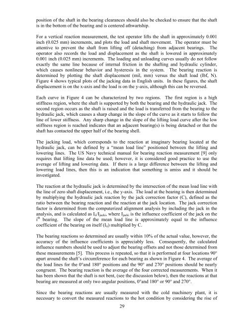
position of the shaft in the bearing clearances should also be checked to ensure that the shaft<br />
is in the bottom of the bearing <strong>and</strong> is centered athwartship.<br />
For a vertical reaction measurement, the test operator lifts the shaft in approximately 0.001<br />
inch (0.025 mm) increments, <strong>and</strong> plots the load <strong>and</strong> shaft movement. The operator must be<br />
attentive to prevent the shaft from lifting off (detaching) from adjacent bearings. The<br />
operator also records the load <strong>and</strong> displacement as the shaft is lowered in approximately<br />
0.001 inch (0.025 mm) increments. The loading <strong>and</strong> unloading curves usually do not follow<br />
exactly the same line because of internal friction in the shafting <strong>and</strong> hydraulic cylinder,<br />
which causes nonlinear behavior <strong>and</strong> hysteresis in the system. The bearing reaction is<br />
determined by plotting the shaft displacement (mil, mm) versus the shaft load (lbf, N).<br />
Figure 4 shows typical plots of the jacking data in English units. In these figures, the shaft<br />
displacement is on the x-axis <strong>and</strong> the load is on the y-axis, although this can be reversed.<br />
Each curve in Figure 4 can be characterized by two regions. The first region is a high<br />
stiffness region, where the shaft is supported by both the bearing <strong>and</strong> the hydraulic jack. The<br />
second region occurs as the shaft is raised <strong>and</strong> the load is transferred from the bearing to the<br />
hydraulic jack, which causes a sharp change in the slope of the curve as it starts to follow the<br />
line of lower stiffness. Any sharp change in the slope of the lifting load curve after the low<br />
stiffness region is reached indicates that an adjacent bearing(s) is being detached or that the<br />
shaft has contacted the upper half of the bearing shell.<br />
The jacking load, which corresponds to the reaction at imaginary bearing located at the<br />
hydraulic jack, can be defined by a “mean load line” positioned between the lifting <strong>and</strong><br />
lowering lines. The US Navy technical manual for bearing reaction measurement [9] only<br />
requires that lifting line data be used; however, it is considered good practice to use the<br />
average of lifting <strong>and</strong> lowering data. If there is a large difference between the lifting <strong>and</strong><br />
lowering load lines, then this is an indication that something is amiss <strong>and</strong> it should be<br />
investigated.<br />
The reaction at the hydraulic jack is determined by the intersection of the mean load line with<br />
the line of zero shaft displacement, i.e., the y-axis. The load at the bearing is then determined<br />
by multiplying the hydraulic jack reaction by the jack correction factor (C), defined as the<br />
ratio between the bearing reaction <strong>and</strong> the reaction at the jack location. The jack correction<br />
factor is determined from the computerized alignment analysis by including the jack in the<br />
analysis, <strong>and</strong> is calculated as Iii/Ijacki, where Ijacki is the influence coefficient of the jack on the<br />
i th bearing. The slope of the mean load line is approximately equal to the influence<br />
coefficient of the bearing on itself (Iii) multiplied by C.<br />
The bearing reactions so determined are usually within 10% of the actual value, however, the<br />
accuracy of the influence coefficients is appreciably less. Consequently, the calculated<br />
influence numbers should be used to adjust the bearing offsets <strong>and</strong> not those determined from<br />
these measurements [5]. This process is repeated, so that it is performed at four locations 90°<br />
apart around the shaft’s circumference for each bearing as shown in Figure 4. The average of<br />
the load lines for the 0°<strong>and</strong> 180° positions <strong>and</strong> the 90° <strong>and</strong> 270° positions should be nearly<br />
congruent. The bearing reaction is the average of the four corrected measurements. When it<br />
has been shown that the shaft is not bent, (see the discussion below), then the reactions at that<br />
bearing are measured at only two angular positions, 0°<strong>and</strong> 180° or 90° <strong>and</strong> 270°.<br />
Since the bearing reactions are usually measured with the cold machinery plant, it is<br />
necessary to convert the measured reactions to the hot condition by considering the rise of<br />
29


