Technical and Research Bulletin 3-51 - Amazon Web Services
Technical and Research Bulletin 3-51 - Amazon Web Services
Technical and Research Bulletin 3-51 - Amazon Web Services
Create successful ePaper yourself
Turn your PDF publications into a flip-book with our unique Google optimized e-Paper software.
the bull gear bearings caused by the thermal growth of their foundations <strong>and</strong> housings <strong>and</strong><br />
the influence coefficients of these bearings, as discussed in Section 6.5.<br />
The hydraulic jack method can also detect bent shafts <strong>and</strong> determine the runout of a shaft by<br />
comparing the bearing reactions at shaft positions 90° apart. A bent shaft should be<br />
suspected if the bearing reaction changes significantly with the shaft circumferential position,<br />
although loose flange-coupling bolts can cause the same symptom. The shaft runout at a<br />
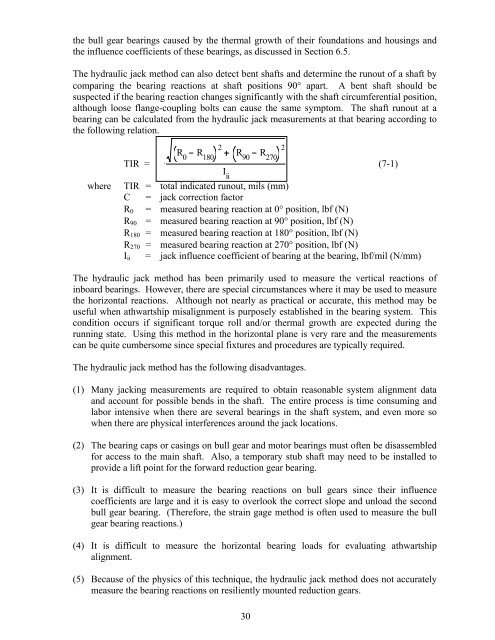
bearing can be calculated from the hydraulic jack measurements at that bearing according to<br />
the following relation.<br />
2<br />
R R R R<br />
0 180 90<br />
TIR = C .<br />
270<br />
(7-1)<br />
I ii<br />
where TIR = total indicated runout, mils (mm)<br />
C = jack correction factor<br />
R0 = measured bearing reaction at 0° position, lbf (N)<br />
R90 = measured bearing reaction at 90° position, lbf (N)<br />
R180 = measured bearing reaction at 180° position, lbf (N)<br />
R270 = measured bearing reaction at 270° position, lbf (N)<br />
Iii = jack influence coefficient of bearing at the bearing, lbf/mil (N/mm)<br />
The hydraulic jack method has been primarily used to measure the vertical reactions of<br />
inboard bearings. However, there are special circumstances where it may be used to measure<br />
the horizontal reactions. Although not nearly as practical or accurate, this method may be<br />
useful when athwartship misalignment is purposely established in the bearing system. This<br />
condition occurs if significant torque roll <strong>and</strong>/or thermal growth are expected during the<br />
running state. Using this method in the horizontal plane is very rare <strong>and</strong> the measurements<br />
can be quite cumbersome since special fixtures <strong>and</strong> procedures are typically required.<br />
The hydraulic jack method has the following disadvantages.<br />
(1) Many jacking measurements are required to obtain reasonable system alignment data<br />
<strong>and</strong> account for possible bends in the shaft. The entire process is time consuming <strong>and</strong><br />
labor intensive when there are several bearings in the shaft system, <strong>and</strong> even more so<br />
when there are physical interferences around the jack locations.<br />
(2) The bearing caps or casings on bull gear <strong>and</strong> motor bearings must often be disassembled<br />
for access to the main shaft. Also, a temporary stub shaft may need to be installed to<br />
provide a lift point for the forward reduction gear bearing.<br />
(3) It is difficult to measure the bearing reactions on bull gears since their influence<br />
coefficients are large <strong>and</strong> it is easy to overlook the correct slope <strong>and</strong> unload the second<br />
bull gear bearing. (Therefore, the strain gage method is often used to measure the bull<br />
gear bearing reactions.)<br />
(4) It is difficult to measure the horizontal bearing loads for evaluating athwartship<br />
alignment.<br />
(5) Because of the physics of this technique, the hydraulic jack method does not accurately<br />
measure the bearing reactions on resiliently mounted reduction gears.<br />
30<br />
2


