Elite igate G512 - Elite Simulation
Elite igate G512 - Elite Simulation
Elite igate G512 - Elite Simulation

You also want an ePaper? Increase the reach of your titles
YUMPU automatically turns print PDFs into web optimized ePapers that Google loves.
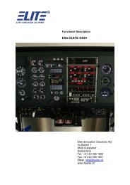
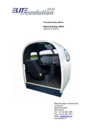
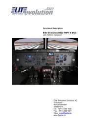
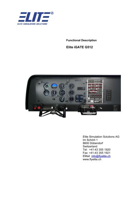
Functional Description<br />
<strong>Elite</strong> iGATE <strong>G512</strong><br />
<strong>Elite</strong> <strong>Simulation</strong> Solutions AG<br />
Im Schörli 1<br />
8600 Dübendorf<br />
Switzerland<br />
Tel: +41-43 355 1920<br />
Fax: +41-43 355 1921<br />
EMail info@flyelite.ch<br />
www.flyelite.ch
<strong>Elite</strong> iGate <strong>G512</strong><br />
©1990 - 2009 <strong>Elite</strong> <strong>Simulation</strong> Solutions AG, all rights reserved<br />
February 2009<br />
section page 2 of 20<br />
Table of Contents<br />
version<br />
1 General.............................................................................................................................................. 4<br />
1.1 Introduction............................................................................................................................... 4<br />
1.2 Trainer certification.................................................................................................................. 4<br />
1.3 Flight modeling......................................................................................................................... 4<br />
1.3.1 Aerodynamic and Performance.......................................................................................... 4<br />
1.3.1.1 Wind effects.......................................................................................................................... 5<br />
1.3.1.2 Atmosphere.......................................................................................................................... 5<br />
1.3.1.3 Ground Handling...................................................................................................................5<br />
1.3.1.4 Take-Off and Climb-Out........................................................................................................5<br />
1.3.1.5 Stalls..................................................................................................................................... 5<br />
1.3.1.6 Landing................................................................................................................................. 5<br />
1.3.1.7 Instrument Responses.......................................................................................................... 5<br />
1.4 Physical dimensions................................................................................................................ 5<br />
1.5 Trainer computer(s).................................................................................................................. 6<br />
1.6 Navigation computing.............................................................................................................. 6<br />
2 Trainer Systems................................................................................................................................ 7<br />
2.1 Visual system............................................................................................................................ 7<br />
2.2 Instructor station...................................................................................................................... 7<br />
2.2.1 Initial Position...................................................................................................................... 7<br />
2.2.2 Weather Page..................................................................................................................... 7<br />
2.2.3 Control Page....................................................................................................................... 8<br />
2.2.4 MAP Page........................................................................................................................... 8<br />
2.2.5 Visual Control Page............................................................................................................ 8<br />
2.2.5.1 Weather Page / Visual Scene.............................................................................................. 8<br />
2.2.6 Failure description.............................................................................................................. 8<br />
2.2.6.1 Engine................................................................................................................................... 8<br />
2.2.6.2 Electric & Instruments........................................................................................................... 9<br />
2.2.6.3 Gear / Flaps.......................................................................................................................... 9<br />
2.3 Approach / Profile MAP.......................................................................................................... 10<br />
2.3.1 Auto Lesson...................................................................................................................... 10<br />
2.3.2 Record / Replay................................................................................................................ 11<br />
2.3.3 Snapshot........................................................................................................................... 11<br />
2.3.4 Communication System.................................................................................................... 11<br />
2.4 Avionics / Radio System <strong>Simulation</strong>..................................................................................... 11<br />
2.4.1 General............................................................................................................................. 11<br />
2.4.2 Audio System.................................................................................................................... 11<br />
2.4.3 VHF Navigation / Communication System........................................................................ 11<br />
2.4.4 Marker Beacon System..................................................................................................... 11<br />
2.4.5 DME System..................................................................................................................... 11<br />
2.4.6 Transponder System........................................................................................................ 11<br />
2.4.7 ADF System...................................................................................................................... 12<br />
2.5 Aircraft types available........................................................................................................... 12<br />
3 Documentation................................................................................................................................ 12<br />
1.2
<strong>Elite</strong> iGate <strong>G512</strong><br />
©1990 - 2009 <strong>Elite</strong> <strong>Simulation</strong> Solutions AG, all rights reserved<br />
February 2009<br />
section page 3 of 20<br />
version<br />
4 Training........................................................................................................................................... 12<br />
5 Spare Parts...................................................................................................................................... 12<br />
6 Screen Shots Instructor Station.................................................................................................... 13<br />
6.1 Configuration Page................................................................................................................. 13<br />
6.2 Control Page........................................................................................................................... 14<br />
6.3 Malfunction Page.................................................................................................................... 14<br />
6.4 Navigation Modification Page................................................................................................ 15<br />
6.5 Metar Page............................................................................................................................... 16<br />
6.6 Meteo Clouds & Visibility Page.............................................................................................. 17<br />
6.7 Meteo Wind & Turbulence Page............................................................................................ 17<br />
6.8 Map Page................................................................................................................................. 18<br />
6.9 iGate <strong>G512</strong>............................................................................................................................... 19<br />
1.2
<strong>Elite</strong> iGate <strong>G512</strong><br />
©1990 - 2009 <strong>Elite</strong> <strong>Simulation</strong> Solutions AG, all rights reserved<br />
February 2009<br />
section page 4 of 20<br />
1 General<br />
1.1 Introduction<br />
version<br />
iGATE is an acronym for "integrated General Aviation Training Environment." It is integrated,<br />
meaning that all required digital devices, hardware components and software interface as an<br />
integral part of one system. This is not a new concept as older analogue electromechanical<br />
trainers manufactured in the 70's and 80's were powered by a single electrical source.<br />
The uniqueness is that iGATE trainers with their digital components combine several new<br />
technologies to provide a simulator with state-of-the-art flight dynamics for several types of<br />
aircraft, and other training capabilities at a single training station. A station that can be used<br />
on a desktop or used in an enclosed cockpit environment.<br />
1.2 Trainer certification<br />
The iGATE <strong>G512</strong> can be upgraded toward JAR STD 3A FNPT I or FNPT II. In case of an<br />
upgrade, the <strong>G512</strong> will be modified with a control loading unit, mock up and a Qualification<br />
Test Guide to assure the quality at any time. All Software changes which are related to the<br />
certification are implemented as well.<br />
1.3 Flight modeling<br />
The iGATE's precise aerodynamic flight modelling assures that each aircraft's flight<br />
characteristics are predictable and expected. iGATE combines aircraft known "book" data<br />
with data collected from actual aircraft flight tests to form the foundation of each flight model.<br />
The lengthy design process yields an acceptable flight model only after numerous cycles of<br />
testing, refinement, and re-testing.<br />
1.3.1 Aerodynamic and Performance<br />
The aerodynamic flight simulation will widely reproduce the flight characteristics of above<br />
mentioned Aircraft.<br />
The simulation of the flight performance is based upon a math model which has been<br />
constantly improved during the last ten years. Full consideration is given to all variable<br />
surfaces and their effects. <strong>Simulation</strong> includes:<br />
� Variation of aeroplane longitudinal, lateral and directional stability with altitude,<br />
airspeed and gross weight<br />
� Single engine Characteristics for one engine out is simulated (asymmetric thrust<br />
effects)<br />
� Stall characteristics<br />
� Ground handling characteristics<br />
� Attitude Indicator has a range, Pitch +50° / -30°, Bank +/- 90° (Training of<br />
unusual attitudes)<br />
1.2
<strong>Elite</strong> iGate <strong>G512</strong><br />
©1990 - 2009 <strong>Elite</strong> <strong>Simulation</strong> Solutions AG, all rights reserved<br />
February 2009<br />
section page 5 of 20<br />
version<br />
1.3.1.1 Wind effects<br />
The effect of wind from any direction, at speeds from zero to sixty knots is realistically<br />
simulated and controlled by the instructor. The wind shows the correct effect on the ground<br />
track display during in-flight operation.<br />
1.3.1.2 Atmosphere<br />
Variation of temperature, pressure and density with altitude does follow the ISA standard<br />
model.<br />
1.3.1.3 Ground Handling<br />
<strong>Simulation</strong> includes turning effects due to rudders, brakes and nose wheel steering,<br />
representative flare and touch down effects. Also asymmetric thrust effects are simulated.<br />
1.3.1.4 Take-Off and Climb-Out<br />
With parking brake set and applied power, proper air plane pitch effects are simulated.<br />
During take-off, heading control can be accomplished via the use of nose wheel steering<br />
and/or rudder.<br />
1.3.1.5 Stalls<br />
There is full representation of the ”approach to Stall” and the recovery from it. Stall is<br />
simulated by cockpit instruments and associated flight characteristics.<br />
The influence of airplane attitude, gross weight, configuration and altitude is also simulated.<br />
1.3.1.6 Landing<br />
The following is simulated during the landing phase:<br />
� Rate of descent versus speed, power setting and wind conditions<br />
� Control approach response<br />
� Stall speeds in the approach and landing configuration<br />
� Ground roll and deceleration<br />
Ground effects (including wind effects) and air to ground transients are simulated to the best<br />
available data, representative of the in-ground effect characteristics of the actual flight.<br />
1.3.1.7 Instrument Responses<br />
Instrument responses to actual air plane responses reflect, but are not limited to:<br />
� Aeroplane slip and rate of turn<br />
� Rate of turn, as a function of bank angle and airspeed<br />
� Attitude, altitude, rate of climb and trim changes with gear position and flap<br />
setting changes<br />
� Pitch attitude, as a function of gross weight and airspeed<br />
1.4 Physical dimensions<br />
The trainer iGATE <strong>G512</strong> dimensions are (w/h/d) 1.4 m x 0.46 m x 0.72 m. The weight is<br />
approximately 50kg.<br />
1.2
<strong>Elite</strong> iGate <strong>G512</strong><br />
©1990 - 2009 <strong>Elite</strong> <strong>Simulation</strong> Solutions AG, all rights reserved<br />
February 2009<br />
section page 6 of 20<br />
1.5 Trainer computer(s)<br />
All computing is performed with standard Windows based PC computers.<br />
version<br />
In case of an external Visual System, a TCP/IP connection is used between the Computers.<br />
1.6 Navigation computing<br />
Navigation database and navigation computing is based on WGS84 system.<br />
1.2
<strong>Elite</strong> iGate <strong>G512</strong><br />
©1990 - 2009, <strong>Elite</strong> <strong>Simulation</strong> Solutions AG, all rights reserved<br />
February 2009<br />
section page 7 of 20<br />
2 Trainer Systems<br />
2.1 Visual system<br />
version<br />
An external Visual system RealView or GenView is optionally avialable for the following<br />
areas: Switzerland (Real View), Western Europe, USA, Australia, New Zealand, India,<br />
China, Turkey, South Amerika and South Africa.<br />
The visual display database allows to fly in the virtual world with accurate digital elevation<br />
models (DEM) and vector data accurately depicting rivers, lakes, highways, railroads and<br />
built up areas. In addition, every airport environment is highly rendered with runway<br />
designators, appropriate runway lighting, approach light systems and properly lighted<br />
generic taxiways. Inherent to the DEM is a fully programmable dynamic weather system that<br />
further enhances the realism of flight by providing 3-D obstructions to visibility, cloud<br />
coverage and several transition zones or layers for IFR, MVFR, SVFR or VFR on top. While<br />
utilizing actual downloadable METAR reports, it is possible to create a real-time flight<br />
experience and save the most challenging weather scenarios for recurrent training.<br />
2.2 Instructor station<br />
The instructor has access to the following pages, where he can also edit the relevant<br />
parameters via Keyboard and/or Mouse input.<br />
� Initial Position<br />
� Weather / Atmospheric Conditions<br />
� Aircraft Conditions<br />
� Map Page (Displays Airports and facilities for quick selection)<br />
� Visual Control<br />
� METAR Page<br />
� Malfunction Page<br />
� Control Page<br />
� Configuration Page<br />
2.2.1 Initial Position<br />
The Initial Position (map page) gives the Instructor access to predefined positions on ground<br />
as well as in the air with defined aircraft loading, Cockpit Instrument settings, weather<br />
conditions and malfunctions.<br />
2.2.2 Weather Page<br />
The weather page contains information concerning the atmospheric conditions in the<br />
simulated environment. Parameters such as sea level temperature, sea level pressure, wind<br />
speed and direction, air turbulence, etc. are variable and the instructor has the possibility to<br />
modify these by inserting the desired values using the mouse. ISA standard day parameters<br />
are default values. All conditions can be saved and stored within a time frame where<br />
changes occur.<br />
1.2
<strong>Elite</strong> iGate <strong>G512</strong><br />
©1990 - 2009, <strong>Elite</strong> <strong>Simulation</strong> Solutions AG, all rights reserved<br />
February 2009<br />
section page 8 of 20<br />
Variable limits are as follows:<br />
� Sea Level Temp. -55°C to +55°C<br />
version<br />
� Sea Level Pressure 28.00 to 31.00 in./Hg (also displays in HPA)<br />
� Wind Direction 0° to 359°<br />
� Wind Speed 0 to 60 knots<br />
� Wind turbulence level 1 to 12<br />
� Pressure Altitude -1000 ft to aeroplanes ceiling<br />
2.2.3 Control Page<br />
The control page displays those parameters which apply to the simulated air plane. The<br />
instructor is able to modify certain parameters and where applicable, those changes<br />
automatically update related parameters affected by the change.<br />
Parameters which are changeable by the Instructor:<br />
� ZERO FUEL WEIGHT<br />
� LEFT USABLE FUEL<br />
� RIGHT USABLE FUEL<br />
� LOAD<br />
2.2.4 MAP Page<br />
The map Page contains all facilities and airports, based on Navigational Databases. The<br />
instructor is able to select the Runway, reposition the air plane to any map position and also<br />
to modify all facilities.<br />
2.2.5 Visual Control Page<br />
The Visual Control Page contains all the means to set up the Visual Scene. It features high<br />
resolution runways and taxiways and a complete approach light system including PAPI/VASI,<br />
EFAS and REIL – systems.<br />
Fog, haze, cloud layers and day to night transition allow to create realistic weather situations.<br />
The positions of sun and moon are calculated from the current time and date. The Visual<br />
System such as the RealView or GenView is an option to the iGATE <strong>G512</strong>.<br />
2.2.5.1 Weather Page / Visual Scene<br />
The Weather page is used to set weather conditions for the visual scene.<br />
Parameters which are changeable by the Instructor:<br />
� Visibility<br />
� Cloud Layer definition height and depth (up to three layers)<br />
� Cloud type few sct bcn ovc<br />
Pre-selected Weather conditions can be saved and stored.<br />
2.2.6 Failure description<br />
2.2.6.1 Engine<br />
Engine power loss selectable time frame between 0 and 99 min<br />
1.2
<strong>Elite</strong> iGate <strong>G512</strong><br />
©1990 - 2009, <strong>Elite</strong> <strong>Simulation</strong> Solutions AG, all rights reserved<br />
February 2009<br />
section page 9 of 20<br />
Oil pressure as above<br />
Oil temperature as above<br />
Cylinder temp. as above<br />
Engine power loss as above<br />
Oil pressure as above<br />
Oil temp. as above<br />
Cylinder temp as above<br />
2.2.6.2 Electric & Instruments<br />
Attitude Indicators as above<br />
Directional Gyro as above<br />
HSI as above<br />
Vertical Speed as above<br />
Airspeed Indicator as above<br />
Turn/bank coordinator as above<br />
Vacuum pump as above<br />
Static system as above<br />
Pitot freeze as above<br />
Pitot & drain freeze as above<br />
Electrical system as above<br />
Nav1 receiver as above<br />
CDI/LOC selectable time frame between 0 and 99 min<br />
GS as above<br />
Nav2 receiver as above<br />
CDI/LOC as above<br />
GS as above<br />
DME as above<br />
ADF receiver as above<br />
ADF antenna as above<br />
Transponder as above<br />
2.2.6.3 Gear / Flaps<br />
Gear as above<br />
Flaps as above<br />
version<br />
The malfunction page displays all armed and failed instruments. The Instructor is able to<br />
clear any malfunction individually and also clear all malfunctions with one input.<br />
1.2
<strong>Elite</strong> iGate <strong>G512</strong><br />
©1990 - 2009, <strong>Elite</strong> <strong>Simulation</strong> Solutions AG, all rights reserved<br />
February 2009<br />
section page 10 of 20<br />
2.3 Approach / Profile MAP<br />
version<br />
The Approach / Profile MAP displays the geographical area, in respect to latitude and<br />
longitude, with all navigational aids displayed that are present in the NAV DATA BASE. The<br />
following data’s are displayed on the same page:<br />
� aeroplane position (lat., long.)<br />
� aeroplane heading<br />
� aeroplane altitude<br />
� indicated airspeed<br />
� aeroplane track<br />
� Transponder code and mode<br />
The area map is used to follow the air plane over an area selectable from 1.0 to 300 NM.<br />
zoom range. The NAV Aids are displayed as Symbols and the identifier are also visible on<br />
screen. To prevent the map from becoming too cluttered, it is possible to switch off NAV<br />
facilities according to the selected zoom level.<br />
The following instructor controllable functions are available on the Map page:<br />
� MAP SCALE 1.0 to 300 NM<br />
� After the aeroplane flies past the area map boundary, it will hold the previous<br />
selected map scale<br />
� TRACK ERASE This clears the current track and will begin a new one<br />
� RADIAL/BEARING DISPLAYS This feature will enable the instructor to read the<br />
Radial or Bearing of the flight of NAV AIDS (ILS, VOR, NDB, etc.) from the map<br />
� SWITCH TO PROFILE VIEW When selected, the area map will automatically<br />
display aeroplane speed, Flaps position, Gear position, Altitude and deviation to<br />
Glide Slope. The profile view is scalable<br />
The Profile view displays the ILS capture area and shows both vertical and horizontal track<br />
relative to the glide slope and localizer position. It shows the air plane position in relationship<br />
of the selected ILS. Also, all associated marker beacons are displayed on both approach<br />
plans.<br />
In relationship to the glide slope and localizer, the air plane's altitude and position is<br />
indicated as line on both approach plans. Along the bottom of the approach profile the map<br />
range is been displayed.<br />
The following information is also displayed:<br />
� Distance to touchdown in NM or KM<br />
� Aeroplane height in feet above ground level, IAS, HDG<br />
� Localizer deviation<br />
� Glide slope deviation (half- and full deflection)<br />
1.2
<strong>Elite</strong> iGate <strong>G512</strong><br />
©1990 - 2009, <strong>Elite</strong> <strong>Simulation</strong> Solutions AG, all rights reserved<br />
February 2009<br />
section page 11 of 20<br />
2.3.1 Auto Lesson<br />
version<br />
Duplication of mission for all trainees. Trainee can be confronted with a well defined training<br />
scenario. A utility is available for easy set up of these lessons.<br />
2.3.2 Record / Replay<br />
Part of the lesson can be recorded and replayed for debriefing purposes. The maximum<br />
recording time is 60 minutes.<br />
2.3.3 Snapshot<br />
This will create a file with all map related parameters, which can saved or printed for<br />
debriefing purposes.<br />
2.3.4 Communication System<br />
An external Intercom is available at customer request.<br />
2.4 Avionics / Radio System <strong>Simulation</strong><br />
2.4.1 General<br />
All avionics operate as they would in the actual air plane, except as explained in this section.<br />
� Audio Panel (Software only)<br />
� NAV/COM Receiver (Bendix/King KX 165 - 25)<br />
� ADF Receiver (Bendix/King KR 87)<br />
� DME Display/Control (Bendix/King KDI 572)<br />
� GPS Receiver (Trimble 2000 Approach Plus)<br />
� Marker Beacon Receiver (Bendix/King KR 21)<br />
2.4.2 Audio System<br />
The audio control system simulates NAV, COMM, ADF, Marker Audio and Intercom.<br />
2.4.3 VHF Navigation / Communication System<br />
The KX 165 - 25 operates as in the actual air plane with the exception that the COMM part<br />
does only display the Frequency and has no effect on communication between Instructor<br />
and pilot. An ATIS System is installed.<br />
2.4.4 Marker Beacon System<br />
The KR 21 marker beacon receiver simulates the aural outputs distributed to the respective<br />
audio systems.<br />
2.4.5 DME System<br />
The DME system simulates according to the approved airplane data. The Distance<br />
Measuring system provides digital readout of slant distance to a DME or VOR/TACAN<br />
ground facility.<br />
1.2
<strong>Elite</strong> iGate <strong>G512</strong><br />
©1990 - 2009, <strong>Elite</strong> <strong>Simulation</strong> Solutions AG, all rights reserved<br />
February 2009<br />
section page 12 of 20<br />
2.4.6 Transponder System<br />
version<br />
The KT 71 Transponder reply light illuminates when the IDENT button is pressed, after<br />
release of this button it extinguishes after approx. 10 seconds. The Transponder mode and<br />
code is display in the instructors map page.<br />
2.4.7 ADF System<br />
The ADF system simulates according to the approved airplane data.<br />
2.5 Aircraft types available<br />
Currently the following aircraft configurations are available for the iGATE G1000 PTT:<br />
� Cessna C172R<br />
� Cessna C172RG<br />
� Beech Baron B58<br />
� Beech Bonanza A36<br />
� Beech Duchess 76<br />
� Beech King Air B200<br />
� Piper Seneca III<br />
� Piper Arrow<br />
� Piper Arrow IV<br />
� Piper Archer III<br />
3 Documentation<br />
� Software operating manual<br />
4 Training<br />
� Basic 1-day Instructor training at ELITE HQ included<br />
� Basic 1-day Hardware maintenance training at ELITE HQ included<br />
5 Spare Parts<br />
Spare parts include heading bug module (Avionics Panel).<br />
1.2
<strong>Elite</strong> iGate <strong>G512</strong><br />
©1990 - 2009, <strong>Elite</strong> <strong>Simulation</strong> Solutions AG, all rights reserved<br />
February 2009<br />
section page 13 of 20<br />
6 Screen Shots Instructor Station<br />
6.1 Configuration Page<br />
version<br />
1.2
<strong>Elite</strong> iGate <strong>G512</strong><br />
©1990 - 2009, <strong>Elite</strong> <strong>Simulation</strong> Solutions AG, all rights reserved<br />
February 2009<br />
section page 14 of 20<br />
6.2 Control Page<br />
6.3 Malfunction Page<br />
version<br />
1.2
<strong>Elite</strong> iGate <strong>G512</strong><br />
©1990 - 2009, <strong>Elite</strong> <strong>Simulation</strong> Solutions AG, all rights reserved<br />
February 2009<br />
section page 15 of 20<br />
6.4 Navigation Modification Page<br />
version<br />
1.2
<strong>Elite</strong> iGate <strong>G512</strong><br />
©1990 - 2009, <strong>Elite</strong> <strong>Simulation</strong> Solutions AG, all rights reserved<br />
February 2009<br />
section page 16 of 20<br />
6.5 Metar Page<br />
connect FSTD to Internet to download hourly METAR updates<br />
version<br />
1.2
<strong>Elite</strong> iGate <strong>G512</strong><br />
©1990 - 2009, <strong>Elite</strong> <strong>Simulation</strong> Solutions AG, all rights reserved<br />
February 2009<br />
section page 17 of 20<br />
6.6 Meteo Clouds & Visibility Page<br />
6.7 Meteo Wind & Turbulence Page<br />
version<br />
1.2
<strong>Elite</strong> iGate <strong>G512</strong><br />
©1990 - 2009, <strong>Elite</strong> <strong>Simulation</strong> Solutions AG, all rights reserved<br />
February 2009<br />
section page 18 of 20<br />
6.8 Map Page<br />
version<br />
1.2
<strong>Elite</strong> iGate <strong>G512</strong><br />
©1990 - 2009, <strong>Elite</strong> <strong>Simulation</strong> Solutions AG, all rights reserved<br />
February 2009<br />
section page 19 of 20<br />
6.9 iGate <strong>G512</strong><br />
version<br />
1.2
<strong>Elite</strong> iGate <strong>G512</strong><br />
©1990 - 2009, <strong>Elite</strong> <strong>Simulation</strong> Solutions AG, all rights reserved<br />
February 2009<br />
section page 20 of 20<br />
version<br />
1.2