Illustration Index - Elite Simulation
Illustration Index - Elite Simulation
Illustration Index - Elite Simulation

You also want an ePaper? Increase the reach of your titles
YUMPU automatically turns print PDFs into web optimized ePapers that Google loves.
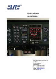
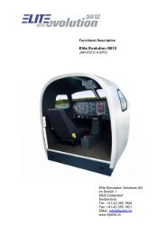
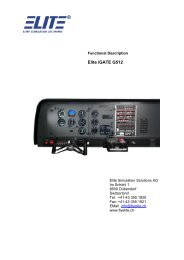
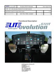
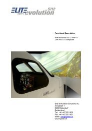
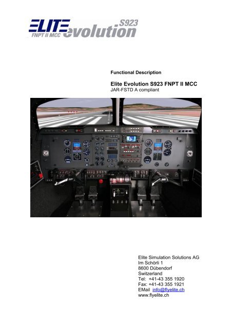
Functional Description<br />
<strong>Elite</strong> Evolution S923 FNPT II MCC<br />
JAR-FSTD A compliant<br />
<strong>Elite</strong> <strong>Simulation</strong> Solutions AG<br />
Im Schörli 1<br />
8600 Dübendorf<br />
Switzerland<br />
Tel: +41-43 355 1920<br />
Fax: +41-43 355 1921<br />
EMail info@flyelite.ch<br />
www.flyelite.ch
<strong>Elite</strong> Evolution S923 FNPT II MCC<br />
©1990 - 2010 <strong>Elite</strong> <strong>Simulation</strong> Solutions AG, all rights reserved<br />
January 2010<br />
section page 2 of 58<br />
Table of Contents<br />
version<br />
1 Functional Description Summery.................................................................................................... 6<br />
1.1 General...................................................................................................................................... 6<br />
1.2 Scope......................................................................................................................................... 6<br />
1.3 General Configuration.............................................................................................................. 6<br />
1.3.1 Cockpit................................................................................................................................ 8<br />
1.3.2 Instructor Station................................................................................................................. 8<br />
1.3.3 Dynamic Control Loading.................................................................................................... 8<br />
1.3.4 External Visual System....................................................................................................... 8<br />
1.3.5 Computer System............................................................................................................... 8<br />
1.4 Maintenance and Support........................................................................................................ 9<br />
1.4.1 Documentation.................................................................................................................... 9<br />
1.4.1.1 Operating Manuals............................................................................................................... 9<br />
1.4.1.2 Maintenance Manuals and Associated Documents..............................................................9<br />
1.4.1.3 Computer and Peripheral Manuals....................................................................................... 9<br />
1.4.2 Spare Parts......................................................................................................................... 9<br />
1.4.2.1 General................................................................................................................................. 9<br />
1.4.2.2 <strong>Elite</strong> Evolution S923 FNPT II MCC Spare Parts................................................................... 9<br />
1.4.2.3 Computer Spare Parts.......................................................................................................... 9<br />
1.4.3 Tools and Test Equipment ................................................................................................. 9<br />
1.4.4 Maintainability..................................................................................................................... 9<br />
1.4.5 Standardization................................................................................................................. 10<br />
1.4.6 Warranty........................................................................................................................... 10<br />
2 Description of flight deck............................................................................................................... 11<br />
2.1 General.................................................................................................................................... 11<br />
2.1.1 Cockpit.............................................................................................................................. 11<br />
2.1.2 Aircraft Parts..................................................................................................................... 11<br />
2.1.3 Panel Layout..................................................................................................................... 12<br />
2.1.3.1 Overview............................................................................................................................. 12<br />
2.1.3.2 Pilot Fuel Control Side Panel..............................................................................................13<br />
2.1.3.3 Copilot Circuit Panel........................................................................................................... 14<br />
2.1.3.4 Pilot Subpanel A................................................................................................................. 14<br />
2.1.3.5 Pilot Subpanel B................................................................................................................. 16<br />
2.1.3.6 Copilot Subpanel A............................................................................................................. 17<br />
2.1.3.7 Gear Control Panel............................................................................................................. 18<br />
2.1.3.8 Trim Wheels....................................................................................................................... 19<br />
2.1.3.9 Avionics Rack..................................................................................................................... 21<br />
2.1.3.10 GPS.................................................................................................................................. 22<br />
2.1.3.11 Primary Flight Controls.................................................................................................... 24<br />
2.2 Instrument Panel Technical Realization............................................................................... 24<br />
2.3 Simulated Instruments........................................................................................................... 24<br />
2.4 Optional aircraft (non MCC)................................................................................................... 24<br />
3 Instructor Station............................................................................................................................ 25<br />
3.1 Instructor Station Features.................................................................................................... 25<br />
3.1
<strong>Elite</strong> Evolution S923 FNPT II MCC<br />
©1990 - 2010 <strong>Elite</strong> <strong>Simulation</strong> Solutions AG, all rights reserved<br />
January 2010<br />
section page 3 of 58<br />
version<br />
3.2 Pages Overview...................................................................................................................... 25<br />
3.2.1 Initial Position.................................................................................................................... 25<br />
3.2.2 Meteo Pages..................................................................................................................... 26<br />
3.2.3 Control Page..................................................................................................................... 29<br />
3.2.4 MAP Page......................................................................................................................... 29<br />
3.2.5 Navigation Modification Page............................................................................................ 31<br />
3.2.6 Configuration Page........................................................................................................... 32<br />
3.2.7 Malfunctions Page............................................................................................................ 32<br />
3.2.7.1 Individual Instrument Failures.............................................................................................32<br />
3.2.7.2 System Failures.................................................................................................................. 32<br />
3.2.7.3 Receiver Failures................................................................................................................ 32<br />
3.2.7.4 Transponder....................................................................................................................... 32<br />
3.2.7.5 Gear / Flaps........................................................................................................................ 32<br />
3.2.7.6 Engines............................................................................................................................... 33<br />
3.2.8 Aircraft-State Snapshot..................................................................................................... 33<br />
3.2.9 Communication System.................................................................................................... 33<br />
4 Dynamic Control Loading (DCL).................................................................................................... 34<br />
4.1 General Description................................................................................................................ 34<br />
4.2 Safety System......................................................................................................................... 34<br />
5 Computer System and Peripherals............................................................................................... 35<br />
5.1 Hardware................................................................................................................................. 35<br />
5.2 Programming Language......................................................................................................... 35<br />
5.3 Maintenance Capabilities....................................................................................................... 35<br />
5.4 System Spare Capacity.......................................................................................................... 35<br />
5.5 Diagnostic............................................................................................................................... 35<br />
6 Description of <strong>Simulation</strong>.............................................................................................................. 36<br />
6.1 Aerodynamic and Performance............................................................................................. 36<br />
6.1.1 Wind Effects..................................................................................................................... 36<br />
6.1.2 Atmosphere...................................................................................................................... 36<br />
6.1.3 On Ground Handling......................................................................................................... 36<br />
6.1.4 Take-Off and Climb-Out.................................................................................................... 36<br />
6.1.5 Stalls................................................................................................................................. 36<br />
6.1.6 One Engine Inoperative Performance............................................................................... 36<br />
6.1.7 Landing............................................................................................................................. 36<br />
6.1.8 Instrument Responses...................................................................................................... 37<br />
6.2 Radio Navigation <strong>Simulation</strong>................................................................................................. 37<br />
6.2.1 Radio Navigation Computation......................................................................................... 37<br />
6.3 Aircraft Systems <strong>Simulation</strong>.................................................................................................. 37<br />
6.3.1 Electrical System.............................................................................................................. 37<br />
6.3.2 Engine System.................................................................................................................. 37<br />
6.3.3 Fuel System...................................................................................................................... 38<br />
6.3.4 Pitot Static System............................................................................................................ 38<br />
6.3.5 Landing Gear, Brakes and Nose Wheel Steering Systems............................................... 38<br />
6.3.6 Flight Control System........................................................................................................ 38<br />
6.4 Avionics / Radio System <strong>Simulation</strong>..................................................................................... 38<br />
6.4.1 General............................................................................................................................. 38<br />
3.1
<strong>Elite</strong> Evolution S923 FNPT II MCC<br />
©1990 - 2010 <strong>Elite</strong> <strong>Simulation</strong> Solutions AG, all rights reserved<br />
January 2010<br />
section page 4 of 58<br />
version<br />
6.4.2 Audio System.................................................................................................................... 39<br />
6.4.3 VHF Navigation / Communication System........................................................................ 39<br />
6.4.4 Transponder System ....................................................................................................... 39<br />
6.4.5 ADF System...................................................................................................................... 39<br />
6.4.6 DME System..................................................................................................................... 39<br />
6.4.7 GPS System..................................................................................................................... 39<br />
6.5 Flight Director / Autopilot System......................................................................................... 39<br />
6.6 Sound System......................................................................................................................... 39<br />
7 Visual System.................................................................................................................................. 41<br />
7.1 Three Channel Visual System (standard equipment S923 FNPT II MCC)...........................41<br />
7.1.1 Hardware Setup................................................................................................................ 41<br />
7.1.2 Visual Cues....................................................................................................................... 42<br />
7.1.2.1 Field of View....................................................................................................................... 42<br />
7.1.2.2 Airport Associated Lighting Facilities..................................................................................42<br />
7.1.2.3 Day to night transition......................................................................................................... 42<br />
7.1.2.4 Clouds / Visibility.................................................................................................................42<br />
7.1.2.5 Runway Features................................................................................................................ 42<br />
7.1.2.6 Real Airport Models............................................................................................................ 42<br />
7.1.3 Data and Technology........................................................................................................ 43<br />
7.1.3.1 Digital Terrain Models......................................................................................................... 43<br />
7.1.3.2 Standard Database GenView..........................................................................................43<br />
7.1.3.3 Optional Database RealView.......................................................................................... 44<br />
7.1.3.4 Programming languages used in RealView / GenView...............................................44<br />
8 Project Scheduling......................................................................................................................... 45<br />
8.1 Project Scheduling System.................................................................................................... 45<br />
8.2 Milestone Schedule................................................................................................................ 45<br />
8.3 Project Status Reviews.......................................................................................................... 45<br />
8.4 Project Reports....................................................................................................................... 45<br />
9 Installation....................................................................................................................................... 46<br />
9.1 Site Layout.............................................................................................................................. 46<br />
9.2 Power....................................................................................................................................... 46<br />
9.3 Environmental Considerations.............................................................................................. 46<br />
10 Acceptance Procedure................................................................................................................. 47<br />
10.1 Factory Acceptance.............................................................................................................. 47<br />
10.2 On-site Acceptance.............................................................................................................. 47<br />
10.3 Testing Procedure................................................................................................................ 47<br />
11 On-Device Training....................................................................................................................... 48<br />
11.1 Factory Training.................................................................................................................... 48<br />
12 JAR-FSTD A Acceptance.............................................................................................................. 49<br />
12.1 Formal acceptance of Civil Aviation Authorities throughout Europe...............................49<br />
13 Screen shots & Pictures............................................................................................................... 50<br />
3.1
<strong>Elite</strong> Evolution S923 FNPT II MCC<br />
©1990 - 2010 <strong>Elite</strong> <strong>Simulation</strong> Solutions AG, all rights reserved<br />
January 2010<br />
section page 5 of 58<br />
<strong>Illustration</strong> <strong>Index</strong><br />
version<br />
Image 1: Cockpit Overview....................................................................................................... 7<br />
Image 2: Main Panel............................................................................................................... 12<br />
Image 3: Side Panels..............................................................................................................12<br />
Image 4: Fuel Control Side Panel...........................................................................................13<br />
Image 5: Pilot Subpanel A (Module 1)................................................................................... 15<br />
Image 6: Pilot Subpanel B ( Module 2)................................................................................... 16<br />
Image 7: Copilot Subpanel A (Module 3)................................................................................17<br />
Image 8: Gear Control Panel (Module 5)................................................................................18<br />
Image 9: Pitch trim wheel unit (Module 6).............................................................................. 19<br />
Image 10: Aileron tab / Rudder tab panel (Module 7)............................................................20<br />
Image 11: <strong>Elite</strong> Avionics Rack (Autopilot may be located in glare shield panel).................... 21<br />
Image 12: Apollo GPS ........................................................................................................... 23<br />
Image 13: Trimble GPS ......................................................................................................... 23<br />
Image 14: Meteo wind and turbulence Page.......................................................................... 26<br />
Image 15: Meteo clouds and visibility Page............................................................................27<br />
Image 16: Metar Page............................................................................................................ 28<br />
Image 17: Control Page..........................................................................................................28<br />
Image 18: Map Page...............................................................................................................30<br />
Image 19: Navigation Modification Page................................................................................ 31<br />
Image 20: Configuration Page................................................................................................ 32<br />
Image 21: Malfunctions Page................................................................................................. 33<br />
Image 22: Visual Hardware set up (drawing shows an optional 3 channel set-up)................41<br />
Image 23: Screen shot GenView (Central Switzerland)......................................................... 43<br />
Image 24: Screen shot RealView (Central Switzerland).........................................................44<br />
Image 25: Screen shot King Air B200 Pilot Instruments.........................................................50<br />
Image 26: Screen shot King Air B200 Engine Instruments.................................................... 51<br />
Image 27: Screen shot King Air B200 Copilot Instruments.................................................... 52<br />
Image 28: Screen shot King Air B200 Pilot Instruments, equipped with EFIS....................... 53<br />
Image 29: Screen shot King Air B200 Engine Instruments, equipped with EFIS...................54<br />
Image 30: Screen shot King Air B200 Copilot Instruments, equipped with EFIS...................55<br />
Image 31: S923 FNPT II MCC King Air B200 Cockpit panel, EFIS instruments....................56<br />
Image 32: S923 FNPT II MCC King Air B200 Cockpit, EFIS instruments..............................57<br />
Image 33: S923 FNPT II MCC King Air B200 Cockpit and IOS, standard instruments......... 58<br />
3.1
<strong>Elite</strong> Evolution S923 FNPT II MCC<br />
©1990 - 2010 <strong>Elite</strong> <strong>Simulation</strong> Solutions AG, all rights reserved<br />
January 2010<br />
section page 6 of 58<br />
1 Functional Description Summery<br />
1.1 General<br />
version<br />
This document presents a detailed procurement specification for the<br />
<strong>Elite</strong> Evolution S923 FNPT II MCC, Flight and Navigation Procedures Training Device,<br />
meeting the requirements specified in the JAA document “JAR-FSTD A. Flight and<br />
Navigation Procedures Trainer”, 01 July 1999.<br />
Additionally, optional aircraft models subject to FNPT II level qualification are described<br />
herein.<br />
Definitions:<br />
a) Customer – Name and Address<br />
b) Manufacturer – <strong>Elite</strong> <strong>Simulation</strong> Solutions AG, Dübendorf, Switzerland<br />
c) STD – Synthetic Training Device<br />
d) Flight deck – Cockpit environment replicating the simulated aircraft and in which the<br />
controls and switches will operate as in that aircraft (table based solution).It is<br />
sufficiently enclosed to exclude pilot and instructor distraction and furnished with<br />
ergonomically positioned seats.<br />
e) Cockpit – Instrument panel replicating a generic twin engine turboprop aircraft<br />
instrumentation.<br />
f) Functional - A three - dimensional reproduction or actual aircraft part connected to<br />
system logic or instructor controlled logics.<br />
g) Non-functional (dummy) - A three-dimensional reproduction or actual aircraft part<br />
not connected to system logics.<br />
h) System logics - Limited simulated aircraft systems operation, in accordance to meet<br />
the training requirements.<br />
i) Available Data - Aircraft design data, pilot’s operating handbook, aircraft<br />
maintenance manuals, observations on ground and in the air, paper pencil methods<br />
and pilot survey.<br />
j) Flight Test Data - Data gathered by the aircraft manufacturer and test flights carried<br />
out by the FNPT manufacturer.<br />
1.2 Scope<br />
The <strong>Elite</strong> Evolution S923 FNPT II MCC (two Pilot) shall simulate normal conditions for<br />
ground operations (limited), take-off, in-flight manoeuvres including engine failure<br />
procedures, radio navigation, instrument approaches and landings. Actions by the crew on<br />
the simulated controls in the flight compartment shall interact with simulated system logics<br />
and dependencies in accordance with this specification and the available aircraft data. The<br />
limits of flight and systems are specified herein.<br />
1.3 General Configuration<br />
The <strong>Elite</strong> Evolution S923 FNPT II MCC is consisting of the following major sub assemblies:<br />
3.1
<strong>Elite</strong> Evolution S923 FNPT II MCC<br />
©1990 - 2010 <strong>Elite</strong> <strong>Simulation</strong> Solutions AG, all rights reserved<br />
January 2010<br />
section page 7 of 58<br />
version<br />
a) A cockpit layout representative of a generic twin engine turboprop aircraft, based on<br />
a King Air B200.<br />
Image 1: Cockpit Overview<br />
b) An enclosed instructor station to give the instructor access to the simulation<br />
environment, as well as to a variety of training tools. A graphic display for various<br />
information, area- and approach tracking is also part of this facility.<br />
c) A dynamic control loading system which produces aircraft configuration dependent<br />
control feelings and control travels which respond in a similar manner under the same<br />
flight conditions as in a typical twin engine aircraft.<br />
d) A simulation computer system consisting of a state of the art computer hardware,<br />
complying with the current industry standard and simulation software.<br />
3.1
<strong>Elite</strong> Evolution S923 FNPT II MCC<br />
©1990 - 2010 <strong>Elite</strong> <strong>Simulation</strong> Solutions AG, all rights reserved<br />
January 2010<br />
section page 8 of 58<br />
1.3.1 Cockpit<br />
version<br />
Actual aircraft hardware components are not used – except for the Garmin 430 GPS option.<br />
Factors which have resulted in the use of replicas include:<br />
a) Cost<br />
b) Reliability - Aircraft use is more restrictive (e. g. airworthiness) than STD use.<br />
c) Ease of Maintenance - Maintenance access is necessarily different from the aircraft.<br />
d) Availability - Many aircraft components have unacceptable long lead times leading<br />
to delays in FNPT delivery.<br />
1.3.2 Instructor Station<br />
The instructor station, consisting of two 17” TFT Flat screens will give the instructor access<br />
to the following functions:<br />
� Environment conditions<br />
� Aircraft status<br />
� Freeze selection<br />
� Repositions<br />
� Pre-selection of environmental conditions<br />
� Malfunction selection<br />
� Selection of visual conditions<br />
� Navigation area selection<br />
� Simulated ATC communication with the cockpit crew<br />
� Selection of initial conditions<br />
� FNPT & QTG control page<br />
� Visual setup page<br />
1.3.3 Dynamic Control Loading<br />
The dynamic control loading system provides the pilot and copilot with a precise, repeatable<br />
control force and natural control response. A safety system is implemented, to protect both<br />
the user and the hardware from equipment failures and human error.<br />
1.3.4 External Visual System<br />
The standard one channel projection system provides a generic representation of the terrain<br />
and conforms to the JAR STD 3A requirements for FNPT II and FNPT II MCC. For more<br />
details refer to chapter 9.1.<br />
1.3.5 Computer System<br />
The computer system consists of the current industry standard PC.<br />
The current industry standard of software is used for the operating system, as well as for the<br />
simulation software. As of January 2005, <strong>Elite</strong> is using standard Windows Operating<br />
Systems.<br />
3.1
<strong>Elite</strong> Evolution S923 FNPT II MCC<br />
©1990 - 2010 <strong>Elite</strong> <strong>Simulation</strong> Solutions AG, all rights reserved<br />
January 2010<br />
section page 9 of 58<br />
1.4 Maintenance and Support<br />
1.4.1 Documentation<br />
version<br />
The documentation for the <strong>Elite</strong> Evolution S923 FNPT II MCC contains the following:<br />
1.4.1.1 Operating Manuals<br />
Software operations manual, includes a general description of the <strong>Elite</strong> Evolution S923<br />
FNPT II MCC software features.<br />
Additional check lists and descriptions to enable the instructor to set-up and operate the STD<br />
under normal and emergency conditions are provided.<br />
1.4.1.2 Maintenance Manuals and Associated Documents<br />
This volume contains information primarily concerning the <strong>Elite</strong> Evolution S923 FNPT II MCC<br />
hardware including technical descriptions and instructions for operating and maintaining of<br />
this hardware. The documents will comprise the following:<br />
� Maintenance Manual<br />
� Vendor Data<br />
� Test Procedures<br />
1.4.1.3 Computer and Peripheral Manuals<br />
The manufacturer’s manuals for the computers and peripherals, giving operating and<br />
maintenance information, will be provided as separate documents.<br />
1.4.2 Spare Parts<br />
1.4.2.1 General<br />
All spares will be ordered at <strong>Elite</strong> Evolution S923 FNPT II MCC order date. The manufacturer<br />
supports the <strong>Elite</strong> Evolution S923 FNPT II MCC complex for five (5) years. In case of<br />
obsolescence of parts, the manufacturer will inform the customer in advance for the<br />
possibility of last buy. Also the manufacturer tries to find a substitute.<br />
1.4.2.2 <strong>Elite</strong> Evolution S923 FNPT II MCC Spare Parts<br />
A spare part quotation will be given on request for the <strong>Elite</strong> Evolution S923 FNPT II MCC<br />
excluding the computer complex. For every type of power supply one spare unit will be kept.<br />
A sufficient number of mechanical and electromechanical parts that are required to support<br />
the <strong>Elite</strong> Evolution S923 FNPT II MCC operation will be kept.<br />
1.4.2.3 Computer Spare Parts<br />
Are kept by the manufacturer in-house. The customer will have a detailed description of the<br />
used computer components to provide a fast exchange if needed.<br />
1.4.3 Tools and Test Equipment<br />
Tools and test programs are used by the manufacturer via remote access to the operator. It<br />
will be necessary that the training device is connected to the Internet (at least 128 kbit/sec<br />
required) in order to grant the accessibility of the system software to the manufacturer. The<br />
access to the system will only take place in close cooperation with the operator.<br />
1.4.4 Maintainability<br />
The <strong>Elite</strong> Evolution S923 FNPT II MCC is designed with maintainability in mind. Every effort<br />
has been made to ensure that there is minimal need to disassemble equipment or to remove<br />
parts. Routing of wire bundles do not interfere with any part or assembly extent. The design<br />
3.1
<strong>Elite</strong> Evolution S923 FNPT II MCC<br />
©1990 - 2010 <strong>Elite</strong> <strong>Simulation</strong> Solutions AG, all rights reserved<br />
January 2010<br />
section page 10 of 58<br />
version<br />
of the <strong>Elite</strong> Evolution S923 FNPT II MCC is in such that – if required - all components are<br />
accessible for replacement and repair.<br />
1.4.5 Standardization<br />
Standard Industry parts and assemblies are used to a high extent wherever it is applicable or<br />
practical. A high grade of common parts are used too.<br />
1.4.6 Warranty<br />
The manufacturer will guarantee for twenty-four (24) months after the installation that the<br />
equipment and any initial spare parts sold to the customer will be free from defects in<br />
materials, workmanship and design under normal use and service. In case of replacing<br />
defective material, it is at the manufacturers discretion if an on site replacement through an<br />
<strong>Elite</strong> technician is needed or if an exchange of the defective material can be done by the<br />
customer. Shipping charges from the manufacturer to the customer are paid by the<br />
manufacturer. Shipping charges from the customer to the manufacturer are paid by the<br />
customer. In case of an on site replacement by the manufacturer, travel cost and<br />
accommodation to and from the customer will be carried by the customer.<br />
3.1
<strong>Elite</strong> Evolution S923 FNPT II MCC<br />
©1990 - 2010 <strong>Elite</strong> <strong>Simulation</strong> Solutions AG, all rights reserved<br />
January 2010<br />
section page 11 of 58<br />
2 Description of flight deck<br />
2.1 General<br />
version<br />
The flight deck is designed to withstand normal loads, shocks and other conditions incidental<br />
to normal operation, transportation and assembly. The structure is sufficiently rigid to assure<br />
that there is no discernible movement of the <strong>Elite</strong> Evolution S923 FNPT II MCC due to<br />
personnel movement or control movement within the flight deck.<br />
The flight deck, including the instructor station, is enclosed. However, the instructor station<br />
does not include a roof. The front windows are fabricated from clear material for an<br />
undisturbed view to the visual scene.<br />
2.1.1 Cockpit<br />
The interior of the flight deck is ergonomically designed to comfortably accommodate the<br />
trainee and the instructor.<br />
Non-aircraft hardware such as switches and knobs are located in the correct location and<br />
provide the same general action. They are in a similar appearance as in the aircraft.<br />
Two chairs with armrests are installed for the pilot and copilot. Both chairs can be moved<br />
forward, backward, up, down and tilted for- and backward to a certain extent. The chairs do<br />
not have shoulder harnesses.<br />
2.1.2 Aircraft Parts<br />
Despite of the circuit breakers, the <strong>Elite</strong> Evolution S923 FNPT II MCC does not include<br />
original aircraft parts (exception: Optional Garmin GNS 430 GPS or Garmin GNS 530 GPS).<br />
3.1
<strong>Elite</strong> Evolution S923 FNPT II MCC<br />
©1990 - 2010, <strong>Elite</strong> <strong>Simulation</strong> Solutions AG, all rights reserved<br />
January 2010<br />
section page 12 of 58<br />
2.1.3 Panel Layout<br />
2.1.3.1 Overview<br />
Image 2: Main Panel<br />
Image 3: Side Panels<br />
version<br />
3.1
<strong>Elite</strong> Evolution S923 FNPT II MCC<br />
©1990 - 2010, <strong>Elite</strong> <strong>Simulation</strong> Solutions AG, all rights reserved<br />
January 2010<br />
section page 13 of 58<br />
2.1.3.2 Pilot Fuel Control Side Panel<br />
Image 4: Fuel Control Side Panel<br />
Name Control Function<br />
version<br />
Stby Pump (L / R) On / Off switch Backup for primary fuel boost pump<br />
Aux Trans Override (L / R) Override / Auto switch Overrides automatic fuel transfer<br />
system<br />
Cross-feed Flow L / Centre / R switch Fuel cross-feed control – select fuel<br />
source for engines<br />
Fuel Quantity Up / momentary Down<br />
switch<br />
Toggles between main tank / aux.<br />
Tank indication<br />
No Transfer (L / R) Push button Indicates missing fuel transfer<br />
DIM / BRT Turn knob Controls brightness of display<br />
elements<br />
Fire wall shut off valve(L / R) Guarded open / closed<br />
switch<br />
Interrupts fuel supply to engine (L / R)<br />
Fire wall valve (L / R) CB CB for fire wall valve (L / R)<br />
Standby Pump (L / R) CB CB for standby pump (L / R)<br />
Aux transfer (L / R) CB CB for aux transfer (L / R)<br />
QTY ind (L / R) CB CB for fuel quantity indicator (L / R)<br />
Press warn (L / R) CB CB for fuel pressure warning (L / R)<br />
Cross feed CB CB for cross-feed system<br />
3.1
<strong>Elite</strong> Evolution S923 FNPT II MCC<br />
©1990 - 2010, <strong>Elite</strong> <strong>Simulation</strong> Solutions AG, all rights reserved<br />
January 2010<br />
section page 14 of 58<br />
2.1.3.3 Copilot Circuit Panel<br />
Name Control Function<br />
Pitch Trim CB CB for electrical pitch trim<br />
Bleed Air Control L CB CB for left bleed air control<br />
version<br />
Bleed Air Control R CB CB for right bleed air control<br />
Gear Motor CB CB for gear motor<br />
Gear Lights CB CB for gear indication lights<br />
Stall Warn CB CB for stall warn unit<br />
Pitot Heat CB CB for pitot heat system<br />
Fire Detection CB CB for fire detection system<br />
COM1/ NAV1 CB CB for COM / NAV 1<br />
COM2 / NAV2 CB CB for COM / NAV 2<br />
ADF / DME / XPDR CB CB for ADF / DME / XPDR<br />
Autopilot CB CB for Autopilot<br />
Generator Ctrl Left CB CB for left generator control<br />
Generator Ctrl Right CB CB for right generator control<br />
Flaps CB CB for flaps motor<br />
Prop Deice Control CB CB for prop de-ice unit<br />
Static Air Source Normal / Alternate switch Controls source for static air<br />
Oxygen supply On / off switch Controls oxygen supply<br />
2.1.3.4 Pilot Subpanel A<br />
3.1
<strong>Elite</strong> Evolution S923 FNPT II MCC<br />
©1990 - 2010, <strong>Elite</strong> <strong>Simulation</strong> Solutions AG, all rights reserved<br />
January 2010<br />
section page 15 of 58<br />
Image 5: Pilot Subpanel A (Module 1)<br />
Name Control Function<br />
version<br />
Mic Normal On / off switch Selector between normal Mic and<br />
Oxygen Mic<br />
Avionics Master On / off switch Power to Avionics System<br />
Inverter No1 Up / off / down switch Controls inverter setting<br />
Batt Master On / off switch Main switch for battery power supply<br />
Gen 1 Left Momentary up / on / off<br />
switch<br />
Gen 2 Right Momentary up / on / off<br />
switch<br />
Generator 1<br />
Generator 2<br />
Eng Auto Ignition Left On / off switch Automatic ignition left<br />
Eng Auto Ignition Right On / off switch Automatic ignition right<br />
Park Brake Push button Brake on / off with the use of the<br />
pedal<br />
Ignition and engine start Left On / off / momentary down<br />
switch<br />
Ignition and engine start Right On / off / momentary down<br />
switch<br />
Ignition and engine start system, left<br />
engine<br />
Ignition and engine start system, right<br />
engine<br />
Ice Vane left On / off switch Controls / opens left ice vane for<br />
alternate engine air inlet<br />
Ice Vane right On / off switch Controls / opens right ice vane for<br />
alternate engine air inlet<br />
Auto Feather Arm / off / Test (momentary<br />
down switch)<br />
Prop gov test Off / Test (momentary up<br />
switch)<br />
Controls automatic feathering of<br />
propeller in case of power / engine<br />
loss<br />
Tests operation of Propeller-<br />
Governors<br />
3.1
<strong>Elite</strong> Evolution S923 FNPT II MCC<br />
©1990 - 2010, <strong>Elite</strong> <strong>Simulation</strong> Solutions AG, all rights reserved<br />
January 2010<br />
section page 16 of 58<br />
2.1.3.5 Pilot Subpanel B<br />
Image 6: Pilot Subpanel B ( Module 2)<br />
Name Control Function<br />
version<br />
Landing On / off switch Controls landing light setting<br />
Taxi On / off switch Controls taxi light setting<br />
Nav On / off switch Controls Nav light setting<br />
Recog On / off switch Controls recog light setting<br />
Beacon On / off switch Controls beacon light setting<br />
Strobe On / off switch Controls strobe light setting<br />
Stall Warn On / off switch Controls stall warn system heating<br />
Wshld Normal / off / Hi switch Controls wind shield system heating –<br />
note the deviation of the magnetic<br />
compass when activated<br />
Brake De-ice On / off switch Controls brake de-ice system<br />
(pneumatic)<br />
De-ice Cycle Momentary single / off /<br />
momentary manual switch<br />
Controls de-ice cycle (pneumatic)<br />
Prop Auto On / off switch Controls automatic prop system<br />
heating<br />
PropManual Momentary on / off switch Controls manual prop system heating<br />
Fuel vent Left On / off switch Controls left fuel vent system heating<br />
Fuel vent Right On / off switch Controls right fuel vent system<br />
heating<br />
Pitot Heat Left On / off switch Controls left pitot heat system<br />
Pitot Heat Right On / off switch Controls right pitot heat system<br />
Prop sync On / off switch Controls prop syncrophaser<br />
3.1
<strong>Elite</strong> Evolution S923 FNPT II MCC<br />
©1990 - 2010, <strong>Elite</strong> <strong>Simulation</strong> Solutions AG, all rights reserved<br />
January 2010<br />
section page 17 of 58<br />
2.1.3.6 Copilot Subpanel A<br />
Image 7: Copilot Subpanel A (Module 3)<br />
Name Control Function<br />
Cabin lights start Bright / Dim / off switch Dummy switch<br />
No Smoke & Fasten Seat belts On / off / FSB switch Dummy switch<br />
Bleed Air Valve Left Open / Envir off / Instr &<br />
Envir off switch<br />
Bleed Air Valve Right Open / Envir off / Instr &<br />
Envir off switch<br />
Controls bleed air valve<br />
Controls bleed air valve<br />
version<br />
Mic Normal / Oxygen switch Selector between normal Mic and<br />
Oxygen Mic<br />
Stall Warn Test Momentary on / off switch Test stall warning<br />
Aft Blower On / off switch Dummy switch<br />
Radiant Heat On / off switch Dummy switch<br />
Fire Det & Fire Ext Test Turn knob EXT L & R, Off,<br />
Det 1, 2, 3<br />
Fire warning and detection test<br />
system<br />
3.1
<strong>Elite</strong> Evolution S923 FNPT II MCC<br />
©1990 - 2010, <strong>Elite</strong> <strong>Simulation</strong> Solutions AG, all rights reserved<br />
January 2010<br />
section page 18 of 58<br />
2.1.3.7 Gear Control Panel<br />
Image 8: Gear Control Panel (Module 5)<br />
Name Control Function<br />
version<br />
Ldg gear control Up / down switch Controls position of landing gear<br />
Gear down indication lights Display elements Red / green / off landing gear status<br />
indication<br />
Gear warn horn Push button Push for gear warn horn silencing<br />
Landing Gear Test Button Push button Press to test Gear lights<br />
Flaps lever Momentary up / down<br />
switch<br />
Cabin Pressure Dump / Press / momentary<br />
down Test switch<br />
Controls flaps settings<br />
Cabin pressure control<br />
Rudder Boost On / off switch For single engine ops<br />
Elev Trim On / off switch Disconnect electrical trim<br />
Yaw Dumper On / off switch Dummy switch<br />
3.1
<strong>Elite</strong> Evolution S923 FNPT II MCC<br />
©1990 - 2010, <strong>Elite</strong> <strong>Simulation</strong> Solutions AG, all rights reserved<br />
January 2010<br />
section page 19 of 58<br />
2.1.3.8 Trim Wheels<br />
Image 9: Pitch trim wheel unit (Module 6)<br />
Name Control Function<br />
version<br />
Note: The pitch trim wheel does not<br />
rotate when using the trim on the<br />
Yoke.<br />
Pitch trim wheel Forward / backward rotation Manual trim change – the trim wheel<br />
does not rotate when using the<br />
electrical pitch trim on the yoke<br />
Pitch trim indication Indication LEDs LED for pitch trim position indication<br />
3.1
<strong>Elite</strong> Evolution S923 FNPT II MCC<br />
©1990 - 2010, <strong>Elite</strong> <strong>Simulation</strong> Solutions AG, all rights reserved<br />
January 2010<br />
section page 20 of 58<br />
Image 10: Aileron tab / Rudder tab panel (Module 7)<br />
Name Control Function<br />
Aileron tab Turn knob L / R Adjusts aileron tab position<br />
Rudder tab Turn knob L / R Adjusts rudder tab position<br />
version<br />
3.1
<strong>Elite</strong> Evolution S923 FNPT II MCC<br />
©1990 - 2010, <strong>Elite</strong> <strong>Simulation</strong> Solutions AG, all rights reserved<br />
January 2010<br />
section page 21 of 58<br />
2.1.3.9 Avionics Rack<br />
Image 11: <strong>Elite</strong> Avionics Rack (Autopilot may be located in glare shield panel)<br />
version<br />
Nav/Comm1<br />
Nav/Comm2<br />
ADF<br />
DME<br />
Transponder<br />
Autopilot<br />
3.1
<strong>Elite</strong> Evolution S923 FNPT II MCC<br />
©1990 - 2010, <strong>Elite</strong> <strong>Simulation</strong> Solutions AG, all rights reserved<br />
January 2010<br />
section page 22 of 58<br />
Name Control Function<br />
NAV / COMM 1 Push buttons, turn knobs,<br />
display elements<br />
NAV / COMM 2 Push buttons, turn knobs,<br />
display elements<br />
ADF Push buttons, turn knobs,<br />
display elements<br />
DME Slide switches, turn knobs,<br />
display elements<br />
Transponder Push button, turn knobs,<br />
display elements<br />
Autopilot Push buttons, rocker switch<br />
(mom. up / mom. down,<br />
neutral), display elements.<br />
Unit may be located in glare<br />
shield panel<br />
2.1.3.10 GPS<br />
For RNAV the following GPS selection is available:<br />
version<br />
Functionality based on KX 165-25<br />
Functionality based on KX 165-25<br />
Functionality based on KR87, with<br />
BFO and ANT mode<br />
Functionality based on KN 62A, with<br />
remote and standalone frequency<br />
Functionality based on KT 70<br />
Transponder unit<br />
Garmin GNS430 (integration of aicraft hardware based simulation unit):<br />
Functionality based on KFC 150,<br />
MODES: FD-ALT-HDG-NAV-APR-BC<br />
Name Control Function<br />
GARMIN GPS Push buttons, turn knobs,<br />
display elements<br />
Functionality based on Garmin GNS<br />
430<br />
3.1
<strong>Elite</strong> Evolution S923 FNPT II MCC<br />
©1990 - 2010, <strong>Elite</strong> <strong>Simulation</strong> Solutions AG, all rights reserved<br />
January 2010<br />
section page 23 of 58<br />
version<br />
UPS 2morrow Apollo GX50 / 55 / 60 / 65 GPS control head (the screen information is shown<br />
on the centre monitor, offset from the control head):<br />
Image 12: Apollo GPS<br />
Name Control Function<br />
Apollo GPS Push buttons, turn knob,<br />
display elements<br />
Functionality based on GX-50 to 65<br />
Trimble 2000 Approach PLUS GPS control head (the screen information is shown on the<br />
centre monitor, offset from the control head):<br />
Image 13: Trimble GPS<br />
Name Control Function<br />
Trimble GPS Push buttons, turn knob,<br />
display elements<br />
Functionality based on Trimble 2000<br />
Approach PLUS GPS system<br />
3.1
<strong>Elite</strong> Evolution S923 FNPT II MCC<br />
©1990 - 2010, <strong>Elite</strong> <strong>Simulation</strong> Solutions AG, all rights reserved<br />
January 2010<br />
section page 24 of 58<br />
version<br />
2.1.3.11 Primary Flight Controls<br />
The standard <strong>Elite</strong> Evolution S923 FNPT II MCC Yokes is based on a generic design and<br />
features an electric pitch trim switch and flight director engage / disengage button for both<br />
Yokes. The Yokes do not cover A/P disconnect push buttons. Two stop watches and chart<br />
holders are placed in the centre of each yoke.<br />
2.2 Instrument Panel Technical Realization<br />
All primary and secondary instruments for the Pilot and Copilot are drawn on TFT displays.<br />
The appearance to the flight crew is similar to the aircraft. All instruments are displayed<br />
close to actual size. Buttons, controls and switches are located according to above (chapter<br />
2.1.3) layout. The instruments are not dimmable except for the Avionics rack.<br />
2.3 Simulated Instruments<br />
All simulated instruments are basically operational as in the aircraft. Instrument face<br />
markings, including graduations, pointers and flags are reproduced as authentically as<br />
possible according to the actual aircraft instruments.<br />
In some cases, instruments or parts of instruments differ in background colour. As an<br />
example, the VSI background colour is slightly brighter than the background colour of the<br />
altimeter. As well, in some cases the manufacturer of original hardware equipment might<br />
provide a choice of different colours. As an example, the flight director can be either green or<br />
magenta. In such cases, <strong>Elite</strong> has chosen one of the listed colours. Changes in colour, size<br />
and shape of instruments or changes on the standard cockpit layout, will require new<br />
technical drawings along with a confirmation of it’s feasibility. The manufacturer will provide<br />
an additional offer, covering the changes according to the specifications agreed upon.<br />
2.4 Optional aircraft (non MCC)<br />
The <strong>Elite</strong> Evolution S923 FNPT II MCC can additionally be configured in one of the following<br />
aircraft configurations:<br />
� Arrow IV<br />
� Baron 58<br />
� Bonanza A36<br />
� Cessna 172 RG<br />
� Seneca III<br />
Aircraft configuration change is easily done by replacing control heads and screen masks<br />
and can be effected in less than 15 minutes. At software launch, the respective model is<br />
loaded. Each of the listed models can be qualified according to FNPT II standards.<br />
3.1
<strong>Elite</strong> Evolution S923 FNPT II MCC<br />
©1990 - 2010, <strong>Elite</strong> <strong>Simulation</strong> Solutions AG, all rights reserved<br />
January 2010<br />
section page 25 of 58<br />
3 Instructor Station<br />
3.1 Instructor Station Features<br />
The main components of the instructor station are:<br />
� Two 17” TFT flat screens<br />
� Keyboard / mouse<br />
� Ink jet printer<br />
version<br />
The instructor’s area is located for optimum crew station view and instructor station's<br />
interface within applicable physical constraints.<br />
The following controls are available via the instructor station:<br />
� Emergency stop for control loading system<br />
� Sounds<br />
� Communication<br />
� Standard atmosphere reset<br />
� External power switches for cockpit, control loading and visual<br />
� Freeze (total, position and fuel freeze)<br />
� Reposition<br />
The instructor has access to the following pages, where he can edit the relevant parameters<br />
via keyboard or mouse input.<br />
� Initial position<br />
� Meteo pages<br />
� Control page<br />
� Visual control<br />
� Map page (displays airports and facilities for quick selection)<br />
� Navigation database modification page<br />
� Configuration page<br />
� Malfunctions page<br />
3.2 Pages Overview<br />
3.2.1 Initial Position<br />
At start-up the STD is set to a predefined initial position. The instructor has the possibility to<br />
load self-created state files containing aircraft loading, cockpit instrument settings, weather<br />
conditions, malfunctions and aircraft position.<br />
3.1
<strong>Elite</strong> Evolution S923 FNPT II MCC<br />
©1990 - 2010, <strong>Elite</strong> <strong>Simulation</strong> Solutions AG, all rights reserved<br />
January 2010<br />
section page 26 of 58<br />
3.2.2 Meteo Pages<br />
The meteorological conditions are controlled on 2 pages:<br />
version<br />
The “Meteo Wind and Turbulence” page contains information concerning the atmospheric<br />
conditions in the simulated environment. Parameters such as temperature, pressure, wind<br />
speed and direction, air turbulence etc. are variable and the instructor has the possibility to<br />
modify these by inserting the desired values via the keyboard and / or mouse. The values<br />
can be specified for 3 layers in the atmosphere. ISA standard day parameters are default<br />
values. All conditions can be saved and stored within a time frame where changes occur.<br />
Variable limits are as follows:<br />
� Temperature range -40°C to +40°C deviation from ISA temperature<br />
� Sea level pressure 27.76 to 31.27 in./Hg (also displays in HPA)<br />
� Wind direction 0° to 359°<br />
� Wind speed 0 to 60 knots<br />
� Wind turbulence level 0 to 12<br />
Image 14: Meteo wind and turbulence Page<br />
The “Meteo Clouds and Visibility” page allows modification of the visibility and cloud types on<br />
three separate layers and enables the instructor to create realistic weather situations. State<br />
files recording weather settings can be created at any time and reloaded when required.<br />
3.1
<strong>Elite</strong> Evolution S923 FNPT II MCC<br />
©1990 - 2010, <strong>Elite</strong> <strong>Simulation</strong> Solutions AG, all rights reserved<br />
January 2010<br />
section page 27 of 58<br />
Image 15: Meteo clouds and visibility Page<br />
version<br />
Actual Metar data can be downloaded from the internet and imported into the simulation for<br />
realistic representation of the weather settings. The positions of sun and moon are<br />
calculated from the current time and date of the simulation.<br />
3.1
<strong>Elite</strong> Evolution S923 FNPT II MCC<br />
©1990 - 2010, <strong>Elite</strong> <strong>Simulation</strong> Solutions AG, all rights reserved<br />
January 2010<br />
section page 28 of 58<br />
Image 16: Metar Page<br />
Image 17: Control Page<br />
version<br />
3.1
<strong>Elite</strong> Evolution S923 FNPT II MCC<br />
©1990 - 2010, <strong>Elite</strong> <strong>Simulation</strong> Solutions AG, all rights reserved<br />
January 2010<br />
section page 29 of 58<br />
3.2.3 Control Page<br />
version<br />
The control page allows date and time manipulation for realistic day to night transition and<br />
light environment. Visual detail settings can be changed from sparse to detailed. Aircraft<br />
load and usable fuel can be changed here as well.<br />
3.2.4 MAP Page<br />
The instructor is able to select the runway or to reposition the aircraft to any desired map<br />
position. The map page contains all facilities and airports, based e. g. on Jeppesen<br />
Navigational Databases. On the map page the following information is visualized:<br />
� Aircraft position (LAT/LONG)<br />
� Aircraft heading<br />
� Aircraft altitude<br />
� Indicated airspeed<br />
� Aircraft track<br />
� Transponder code<br />
The navigational aids are displayed as symbols and their identifier are also visible on<br />
Screen. To prevent the map from becoming too cluttered, a feature to switch off selected<br />
types of navigation stations from the display is available to the instructor. The US victorairways<br />
can also be shown on the map.<br />
Included on the area map page the following instructor controllable functions are available:<br />
� After the aircraft flies past the area map boundary, it will hold the previous selected<br />
map scale.<br />
� TRACK ERASE This clears the current track and will begin a new one.<br />
� SYMBOL DISPLAYS This feature will enable the instructor to blank out types of<br />
NAV AIDS (ILS, VOR, NDB, etc.) from the map.<br />
� INSTRUMENT DISPLAYS The instructor has a choice of miniaturized instruments<br />
to be displayed on the map screen to allow observation of the instrument readout<br />
during the training session or for debriefing purposes (replay function including the<br />
display of the instruments’ status).<br />
� PROFILE VIEW When selected, the area map will additionally display aircraft<br />
speed, Flaps position, Gear position, Altitude and deviation to Glide Slope. The<br />
profile view is scalable.<br />
The Profile view displays the ILS capture area and shows both vertical and horizontal track<br />
relative to the glide slope and localizer position. It shows the aircraft position in relationship<br />
to the selected ILS, clearly depicting glide slope deviation. Additionally, all associated marker<br />
beacons are displayed on both approach plans.<br />
The Flight Path Replay function allows powerful and sophisticated analysing of Pilot action<br />
during STD flight for debriefing purposes. Information available in profile and extended<br />
(aircraft speed, gear and flap settings) view can be displayed on the map page. When<br />
approaching an ILS facility the deviation between the ideal and the actually flown path can<br />
be analysed at any zoom level – half and one degree deflection is visualised on the profile<br />
3.1
<strong>Elite</strong> Evolution S923 FNPT II MCC<br />
©1990 - 2010, <strong>Elite</strong> <strong>Simulation</strong> Solutions AG, all rights reserved<br />
January 2010<br />
section page 30 of 58<br />
version<br />
section of the map page. In case of using the STD in combination with the optional external<br />
visual system, the cross section of the underlying terrain is displayed at any position. The<br />
maximum recording time is 60 minutes.<br />
Print map, zoom functions, database load and state file save functions are standard map<br />
page features.<br />
Image 18: Map Page<br />
3.1
<strong>Elite</strong> Evolution S923 FNPT II MCC<br />
©1990 - 2010, <strong>Elite</strong> <strong>Simulation</strong> Solutions AG, all rights reserved<br />
January 2010<br />
section page 31 of 58<br />
3.2.5 Navigation Modification Page<br />
version<br />
The Navigation Modification Page enables the instructor to modify any facility and airport.<br />
Additional navigational aids can be defined by the instructor. This page can be password<br />
protected.<br />
Image 19: Navigation Modification Page<br />
3.1
<strong>Elite</strong> Evolution S923 FNPT II MCC<br />
©1990 - 2010, <strong>Elite</strong> <strong>Simulation</strong> Solutions AG, all rights reserved<br />
January 2010<br />
section page 32 of 58<br />
3.2.6 Configuration Page<br />
version<br />
The Configuration Page contains one time settings such as volume control, calibration of the<br />
three control axis, damping values for the control axis, UTC time settings.<br />
Aircraft specific data is displayed for reference (critical speeds etc.).<br />
3.2.7 Malfunctions Page<br />
Failures can occur immediately or within a specifiable time window. Random failures can be<br />
activated. The malfunction page displays all armed and failed instruments. The instructor is<br />
able to clear any malfunction individually and also clear all malfunctions with one input.<br />
3.2.7.1 Individual Instrument Failures<br />
Attitude indicator HSI<br />
Altitude VSI<br />
Airspeed indicator Turn/bank coordinator<br />
3.2.7.2 System Failures<br />
Vacuum pump Static system<br />
Pitot freeze Pitot & drain freeze<br />
Electrical system<br />
3.2.7.3 Receiver Failures<br />
Nav1 receiver CDI / LOC / GS<br />
Nav2 receiver CDI / LOC / GS<br />
ADF receiver ADF antenna<br />
3.2.7.4 Transponder<br />
Transponder<br />
3.2.7.5 Gear / Flaps<br />
Gear Flaps<br />
Image 20: Configuration Page<br />
3.1
<strong>Elite</strong> Evolution S923 FNPT II MCC<br />
©1990 - 2010, <strong>Elite</strong> <strong>Simulation</strong> Solutions AG, all rights reserved<br />
January 2010<br />
section page 33 of 58<br />
3.2.7.6 Engines<br />
Engines power loss Oil pressure<br />
Oil temperature Cylinder temp.<br />
3.2.8 Aircraft-State Snapshot<br />
version<br />
This will create a file with all aircraft related parameters such as aircraft position, attitude,<br />
instrument settings, failure settings, meteorological situation. This information can be<br />
reloaded for repeating lessons or recalled for debriefing purposes.<br />
3.2.9 Communication System<br />
Image 21: Malfunctions Page<br />
A standard intercom is installed to communicate as follows: pilot – pilot, instructor – pilot,<br />
instructor – instructor. There is no push to talk switch. The instructor can hear at all times the<br />
pilots.<br />
3.1
<strong>Elite</strong> Evolution S923 FNPT II MCC<br />
©1990 - 2010, <strong>Elite</strong> <strong>Simulation</strong> Solutions AG, all rights reserved<br />
January 2010<br />
section page 34 of 58<br />
4 Dynamic Control Loading (DCL)<br />
4.1 General Description<br />
version<br />
The DCL gives the Pilot and Copilot a realistic control feeling for the aileron, elevator and<br />
rudder controls. The control loading system is controlled via the host computer, so that the<br />
pressure on the primary flight controls will be automatically adjusted in accordance to:<br />
� Flight control position<br />
� Flight control trim setting<br />
� Bank angle<br />
� Slip/skid (resulting from asymmetric thrust conditions)<br />
� Aircraft in flight or on the ground<br />
� Autopilot inputs<br />
� Airspeed<br />
4.2 Safety System<br />
A safety system is incorporated to protect both the user and the <strong>Elite</strong> Evolution S923 FNPT II<br />
MCC from the hazards of in proper operation, equipment failure or power failure. However,<br />
the customer shall under no circumstances manipulate control loading settings as they might<br />
result in a complete damage of the control loading unit.<br />
3.1
<strong>Elite</strong> Evolution S923 FNPT II MCC<br />
©1990 - 2010, <strong>Elite</strong> <strong>Simulation</strong> Solutions AG, all rights reserved<br />
January 2010<br />
section page 35 of 58<br />
5 Computer System and Peripherals<br />
5.1 Hardware<br />
version<br />
The components of the Computer Hardware complies with the current industry standards.<br />
For later upgrades and / or modifications a certain amount of Spare Slots are available. Via a<br />
Keyboard and Monitor the system operator has access to the computer for operation and<br />
maintenance purpose. An ink jet printer is installed as hard copy device to print out instructor<br />
station pages.<br />
5.2 Programming Language<br />
Standard high level programming languages C and C++ are used for implementation of the<br />
flight simulation software.<br />
5.3 Maintenance Capabilities<br />
Tools for maintenance are available at the manufacturer’s site and will allow, with remote<br />
access to the operator, immediate access.<br />
5.4 System Spare Capacity<br />
The computer system has adequate spare capacity in both memory and processing time. In<br />
Average the amount of spare memory will be at least 30%, the spare processing time for the<br />
Cockpit Instruments are at least 40%, for the optional Real View and standard Gen View<br />
Visual at least 20%.<br />
5.5 Diagnostic<br />
Incorporated in the design is a diagnostic system (software) to enable verification of the I/O<br />
device integrity as well as to identify and isolate faulty I/O channels.<br />
3.1
<strong>Elite</strong> Evolution S923 FNPT II MCC<br />
©1990 - 2010, <strong>Elite</strong> <strong>Simulation</strong> Solutions AG, all rights reserved<br />
January 2010<br />
section page 36 of 58<br />
6 Description of <strong>Simulation</strong><br />
6.1 Aerodynamic and Performance<br />
version<br />
The aerodynamic flight simulation will widely reproduce the flight characteristics of a twin<br />
engine aircraft.<br />
The simulation of the flight performance is based on an accurate mathematics model. Full<br />
consideration is given to all variable surfaces and their effects. <strong>Simulation</strong> does include:<br />
� Variation of aircraft longitudinal, lateral and directional stability with altitude, airspeed<br />
and gross weight<br />
� Stall characteristics<br />
� 1-Engine in op. characteristics<br />
� Ground handling characteristics<br />
6.1.1 Wind Effects<br />
The effect of wind from any direction, at speeds from zero to sixty knots is realistically<br />
simulated and controlled by the instructor. The wind does show the correct effect on the<br />
ground track display during in-flight operation of the <strong>Elite</strong> Evolution S923 FNPT II MCC.<br />
6.1.2 Atmosphere<br />
Variation of temperature, pressure and density with altitude does follow the ISA standard<br />
model.<br />
6.1.3 On Ground Handling<br />
<strong>Simulation</strong> does include turning effects due to rudders, brakes and A/C wheel steering,<br />
representative flare and touch down effects. Also asymmetric thrust effects are simulated.<br />
6.1.4 Take-Off and Climb-Out<br />
With parking brake set and applied power, proper aircraft pitch effects are simulated. During<br />
take-off, heading control is accomplished via the use of wheel steering and/or rudder.<br />
6.1.5 Stalls<br />
There is full representation of the ”approach to stall” and the recovery from it. Stall is<br />
simulated by Cockpit instruments and associated flight characteristics.<br />
The influence of aircraft attitude, gross weight, configuration and altitude is also simulated.<br />
6.1.6 One Engine Inoperative Performance<br />
Full representation of 1-Engine in op. characteristics and performance are implemented.<br />
6.1.7 Landing<br />
The following is simulated during the landing phase:<br />
� Rate of descent versus speed, power setting and wind conditions<br />
� Control approach response<br />
3.1
<strong>Elite</strong> Evolution S923 FNPT II MCC<br />
©1990 - 2010, <strong>Elite</strong> <strong>Simulation</strong> Solutions AG, all rights reserved<br />
January 2010<br />
section page 37 of 58<br />
� Stall speeds in the approach and landing configuration<br />
� Ground roll and deceleration<br />
version<br />
Ground effects (including wind effects) and air to ground transients are simulated to the best<br />
available data, representative of the in-ground effect characteristics of the actual flight.<br />
6.1.8 Instrument Responses<br />
Instrument responses to actual aircraft responses do reflect:<br />
� Aircraft slip and rate of turn<br />
� Rate of turn, as a function of bank angle and airspeed<br />
� Attitude, altitude, rate of climb and trim changes with gear position and flap setting<br />
changes<br />
� Pitch attitude, as a function of gross weight and airspeed<br />
6.2 Radio Navigation <strong>Simulation</strong><br />
6.2.1 Radio Navigation Computation<br />
In order to execute the radio navigation simulation function, real world Navigation Databases<br />
are used. Periodical updates are available if necessary. Modification of existing and creation<br />
of new facilities are done using the modification page.<br />
<strong>Elite</strong> is updating on a regular basis the Navigation Database. However, the manufacturer<br />
cannot assure, that on the date of delivery, the Navigation Database is current. In case of an<br />
obsolete Navigation Database, the operator is asked to modify the facilities using <strong>Elite</strong>’s<br />
modification page. Alternatively, <strong>Elite</strong> can upload current Navigation data's via remote<br />
access to the customers FNPT II MCC device.<br />
6.3 Aircraft Systems <strong>Simulation</strong><br />
6.3.1 Electrical System<br />
Changing the status of electricity consumers in the Cockpit (e. g. switching on / off Avionics<br />
panel) are reflected in the consumption of electricity. Should the aircraft’s electrical systems<br />
run on battery only without being constantly fed by the alternator, battery load will decrease.<br />
When running on Standby generator only Nav1 and Comm1 will work.<br />
6.3.2 Engine System<br />
The engine and the associated controls and indicators are simulated as described in the<br />
aircraft data. The basis for the engine and aircraft model is a King Air B200.<br />
<strong>Simulation</strong> of the power plants include engine start on the ground and in the air, normal- and<br />
emergency handling, acceleration, deceleration and shut-down. Variations of the effects of<br />
altitude, airspeed and ambient temperature are included in the performance computations.<br />
Characteristics for the applicable engine and their effect on the flight path are reproduced in<br />
response to engine control selections.<br />
3.1
<strong>Elite</strong> Evolution S923 FNPT II MCC<br />
©1990 - 2010, <strong>Elite</strong> <strong>Simulation</strong> Solutions AG, all rights reserved<br />
January 2010<br />
section page 38 of 58<br />
version<br />
The engine monitoring system has the capability of depicting a realistic representation of<br />
engine operations.<br />
Propeller control and operation are realistically simulated. This includes full range of pitch<br />
control, feathering and propeller governing.<br />
6.3.3 Fuel System<br />
The aircraft fuel system is simulated in accordance with aircraft data. The effects of fuel<br />
depletion is simulated. Fuel quantity indicators are simulated from aircraft data.<br />
6.3.4 Pitot Static System<br />
The aircraft pitot static system is simulated in accordance with aircraft data.<br />
6.3.5 Landing Gear, Brakes and Nose Wheel Steering Systems<br />
The normal landing gear system controls, indicators and warning sounds are simulated<br />
according to the aircraft data.<br />
The simulated aircraft brake system has a realistic force feel and also represents<br />
asymmetrical brake functionality. Parking brake control is simulated.<br />
Nose wheel steering is simulated. Steering forces are felt by the pilot through the rudder<br />
pedals when using a dynamic control loading unit.<br />
6.3.6 Flight Control System<br />
The flight controls are installed for a two Pilot (dual yoke) operations in the Cockpit and<br />
correspond according to the available aircraft data. Realistic force feel and dynamic<br />
response is achieved from aircraft data.<br />
The simulation of trim for elevator, rudder and aileron is provided. Trim position indicators –<br />
Software and Hardware are present for elevator and rudder and reflect system operation.<br />
The aircraft flaps operation is simulated and affects the aircraft’s performance.<br />
6.4 Avionics / Radio System <strong>Simulation</strong><br />
6.4.1 General<br />
All avionics operate as they would in the actual aircraft, except as explained in this section.<br />
Avionics operation is limited by the capabilities of the <strong>Elite</strong> Evolution S923 navigation system.<br />
The avionics of the <strong>Elite</strong> Evolution S923 include the following:<br />
� Audio control Console / Intercom<br />
� NAV/COM Receivers (Bendix/King KX 165 - 25)<br />
� ADF (Bendix/King KR 87)<br />
� DME (Bendix/King KN 62A)<br />
� Transponder (Bendix/King KT 70)<br />
� Autopilot KFC 150<br />
� Apollo GPS GX50, GX55, GX60 and GX65 or<br />
3.1
<strong>Elite</strong> Evolution S923 FNPT II MCC<br />
©1990 - 2010, <strong>Elite</strong> <strong>Simulation</strong> Solutions AG, all rights reserved<br />
January 2010<br />
section page 39 of 58<br />
� Trimble 2000 Approach Plus or<br />
� Garmin GNS 430<br />
6.4.2 Audio System<br />
version<br />
The audio control system simulates NAV, COMM, ADF, Marker audio and Intercom. All<br />
above mentioned Instruments (6.4.1 which produce sounds such as ident or marker sounds<br />
are audible through the loudspeakers or through the headphones.<br />
6.4.3 VHF Navigation / Communication System<br />
The KX 165 - 25 operates as in the actual aircraft with the exception that the COMM part<br />
does only display the Frequency and has no effect on communication between instructor<br />
and pilot. The Navigation part is simulated according to the approved aircraft data.<br />
6.4.4 Transponder System<br />
The Transponder is simulated according to the original KT 70 device.<br />
6.4.5 ADF System<br />
The ADF system is simulated according to the original KR 87 device.<br />
6.4.6 DME System<br />
The DME system is simulated according to the original KN 62A device.<br />
6.4.7 GPS System<br />
An Apollo GPS GX50, GX55, GX60 and GX65 or Trimble 2000 Approach Plus or Garmin<br />
GNS 430 is implemented in the <strong>Elite</strong> Evolution S923 FNPT II MCC. User settings and flight<br />
plans cannot be saved. The type of GPS has to be selected by the customer at order date.<br />
6.5 Flight Director / Autopilot System<br />
The <strong>Elite</strong> Evolution S923 FNPT II MCC has a fully functional automatic flight control system,<br />
including autopilot and flight director, simulating the Bendix/King KFC 150.<br />
6.6 Sound System<br />
The following sounds are simulated if audible in the Cockpit of the <strong>Elite</strong> Evolution S923<br />
FNPT II MCC:<br />
� Engine, propeller<br />
� Landing gear retraction and extension<br />
� Flaps retraction and extension<br />
� Touchdown bumps<br />
� System sounds like Stall warning, indents etc. are present<br />
� ATIS<br />
3.1
<strong>Elite</strong> Evolution S923 FNPT II MCC<br />
©1990 - 2010, <strong>Elite</strong> <strong>Simulation</strong> Solutions AG, all rights reserved<br />
January 2010<br />
section page 40 of 58<br />
� Instrument fan<br />
version<br />
Above mentioned sounds are audible through the loudspeakers or through the Headphones.<br />
3.1
<strong>Elite</strong> Evolution S923 FNPT II MCC<br />
©1990 - 2010, <strong>Elite</strong> <strong>Simulation</strong> Solutions AG, all rights reserved<br />
January 2010<br />
section page 41 of 58<br />
7 Visual System<br />
version<br />
7.1 Three Channel Visual System (standard equipment S923 FNPT II MCC)<br />
The main components are:<br />
Image Generator (Software License and Computer)<br />
XGA-projector and projection screen<br />
Visual Databases according to customer requirements<br />
7.1.1 Hardware Setup<br />
The standard Hardware set up for the three channel Visual system consists of projectors<br />
with front projection screens and a mounting unit.<br />
Image 22: Visual Hardware set up (drawing shows an optional 3<br />
channel set-up)<br />
3.1
<strong>Elite</strong> Evolution S923 FNPT II MCC<br />
©1990 - 2010, <strong>Elite</strong> <strong>Simulation</strong> Solutions AG, all rights reserved<br />
January 2010<br />
section page 42 of 58<br />
7.1.2 Visual Cues<br />
7.1.2.1 Field of View<br />
Horizontal: 40 - 45 degrees per channel<br />
Vertical: 30 - 33 degrees per channel<br />
7.1.2.2 Airport Associated Lighting Facilities<br />
� Approach lighting system<br />
� Runway lighting system<br />
� Taxiway lighting system<br />
� VASI / PAPI lights<br />
� Runway End Identification Lights (REIL)<br />
� Strobe lights<br />
version<br />
7.1.2.3 Day to night transition<br />
The Visual features a realistic time, date and light condition simulation. Sun / Moon rise and<br />
set and changing ambient light are correctly represented based on an accurate astronomic<br />
model.<br />
7.1.2.4 Clouds / Visibility<br />
Variable cloud layers and RVR settings are controllable via modifications on Meteo page.<br />
7.1.2.5 Runway Features<br />
Runways are always dry with textures.<br />
7.1.2.6 Real Airport Models<br />
Real Airport Models can be programmed through the manufacturer upon request.<br />
3.1
<strong>Elite</strong> Evolution S923 FNPT II MCC<br />
©1990 - 2010, <strong>Elite</strong> <strong>Simulation</strong> Solutions AG, all rights reserved<br />
January 2010<br />
section page 43 of 58<br />
7.1.3 Data and Technology<br />
version<br />
7.1.3.1 Digital Terrain Models<br />
Elevation data of global coverage, based on a 1 km resolution grid, is used for the terrain<br />
representation. Based on this data, elevations may differ from actual values due to<br />
interpolation effects. Airport elevation for the 5 airports selected as main training fields will be<br />
within +/- 50 ft of ARP elevation.<br />
If higher accuracy is required, the manufacturer will acquire elevation data with higher<br />
resolution and will locally densify the global model. As like with RealView the customer<br />
shall specify his training requirements. Please contact an <strong>Elite</strong> Sales representative to<br />
discuss further details.<br />
7.1.3.2 Standard Database GenView<br />
GenView displays the landscape based on generic textures. Geographic features such as<br />
lakes, rivers, urban areas, railroads or streets are represented using vector data. The<br />
runway environment consists of approach lights, centerline lights, edge lights, PAPI / VASI<br />
according to Nav Data specifications. Due to the high amount of above mentioned facilities<br />
in each database, the position of the taxiways as well as the lighting of the taxiways (green<br />
for centerline, blue for edge lights) are drawn generically.<br />
Image 23: Screen shot GenView (Central Switzerland)<br />
3.1
<strong>Elite</strong> Evolution S923 FNPT II MCC<br />
©1990 - 2010, <strong>Elite</strong> <strong>Simulation</strong> Solutions AG, all rights reserved<br />
January 2010<br />
section page 44 of 58<br />
version<br />
7.1.3.3 Optional Database RealView<br />
The Real View External Visual System is based on the ViRGIS project (Virtual Reality<br />
Geographic Information System) by the Federal Institute of Technology Zurich. The aim of<br />
ViRGIS is the real-time visualisation of large geographic datasets. Accordingly, RealView<br />
External Visual System creates a realistic model of the geographic scenery by utilising digital<br />
elevation models and satellite images as geospecific textures. By using data of different<br />
sensors with different geometric properties (i. e. Landsat Thematic Mapper data with 25 m,<br />
SPOT 3 / 4 data with 10 m or even Aerial Photographs with down to 1 m geometric<br />
resolution) user‘s needs can be taken into account.<br />
A complex “level of detail” concept is required to cope with the large amounts of data<br />
required for this approach. Both the terrain model and the satellite textures are adapted to<br />
achieve the best image quality without compromising excellent system performance.<br />
Image 24: Screen shot RealView (Central Switzerland)<br />
RealView is available as an option to all FNPT Training Devices and require specifications<br />
from the customer such as coverage or level of detail. Please contact an <strong>Elite</strong> Sales<br />
representative to discuss your needs.<br />
7.1.3.4 Programming languages used in RealView / GenView<br />
The Real View Visual is based on OpenGL. OpenGL ensures excellent image quality and<br />
the currently available video cards offer hardware accelerated fast rendering. The Visual is<br />
based on an object oriented framework of classes written in C++.<br />
3.1
<strong>Elite</strong> Evolution S923 FNPT II MCC<br />
©1990 - 2010, <strong>Elite</strong> <strong>Simulation</strong> Solutions AG, all rights reserved<br />
January 2010<br />
section page 45 of 58<br />
8 Project Scheduling<br />
8.1 Project Scheduling System<br />
version<br />
A project scheduling system with the following features is maintained at the manufacturers<br />
site:<br />
� Milestone Schedule<br />
� Reviews<br />
� Project Reports<br />
8.2 Milestone Schedule<br />
A detailed Milestone Schedule will be discussed and implemented depending on customers<br />
demands and preferences.<br />
8.3 Project Status Reviews<br />
These reviews are held on a regularly basis to ensure that the project is proceeding<br />
according to the approved specification.<br />
8.4 Project Reports<br />
Inputs from Milestone Schedule Meetings and Design Reviews Meetings are used to<br />
generate Project Reports. A copy of these reports are sent to the customer.<br />
3.1
<strong>Elite</strong> Evolution S923 FNPT II MCC<br />
©1990 - 2010, <strong>Elite</strong> <strong>Simulation</strong> Solutions AG, all rights reserved<br />
January 2010<br />
section page 46 of 58<br />
9 Installation<br />
9.1 Site Layout<br />
The operator shall consider the following:<br />
� access doors with at least 85 cm width and 2m height<br />
version<br />
� sufficiently wide access corridors. Preferably you can provide a plan copy of the room<br />
and the access to the room to evaluate whether the material can be carried into<br />
room.<br />
� the <strong>Elite</strong> Evolution S923 FNPT II MCC Mock up with instructor station enclosure size<br />
is 2.50 m x 4.25 m x 2.40 m (w x l x h) and includes a mounting unit for the visual<br />
projection system and a visual projection canvas.<br />
� Two ISDN channels or better (DSL) connection for remote access<br />
� Minimum required room space is 3.5m x 5.0m x 2.5m (w x l x h) please note that a<br />
multi-channel Visual set up requires more space.<br />
9.2 Power<br />
The <strong>Elite</strong> Evolution S923 FNPT II MCC Complex will operate on 110 / 230 V / 50 Hz electric<br />
power. All interfacing equipment (transformers, inverters, etc.) will be provided by the<br />
manufacturer.<br />
The customer shall provide 380 VAC / 50 HZ three phase power through an Europlug CEE<br />
type (32 A) 3 LNPE and related surge protection.<br />
The total electric power consumption for an S923 with one visual channel is maximally 10<br />
kW and consists of the following separable circuits:<br />
� Control loading Unit ~4 kW<br />
� Visual System ~1 kW (one channel)<br />
� Cockpit panel / IOS ~2.5 kW<br />
9.3 Environmental Considerations<br />
Operating<br />
� Temperature: +10 ° C - +25 ° C (Monitor, Projector)<br />
� Humidity: 20 % - 80 %, non-condensing<br />
� Heat dissipation: STD without pilots/instructor 14000 Btu/hr<br />
� The light environment of the STD room must be controllable<br />
3.1
<strong>Elite</strong> Evolution S923 FNPT II MCC<br />
©1990 - 2010, <strong>Elite</strong> <strong>Simulation</strong> Solutions AG, all rights reserved<br />
January 2010<br />
section page 47 of 58<br />
10 Acceptance Procedure<br />
10.1 Factory Acceptance<br />
version<br />
A factory acceptance must be carried out with the customer in accordance with the<br />
Qualification Test Guide and mission flights, which ensure that the <strong>Elite</strong> Evolution S923<br />
FNPT II MCC meets the specified requirements.<br />
10.2 On-site Acceptance<br />
An on-site acceptance will be carried out by <strong>Elite</strong> and the customer to verify the agreed<br />
specifications and to assure the full functionality carried out during the factory acceptance.<br />
10.3 Testing Procedure<br />
The <strong>Elite</strong> Evolution S923 FNPT II MCC evaluation during acceptance shall be accomplished<br />
only when the <strong>Elite</strong> Evolution S923 FNPT II MCC is equipped with all deliverable object<br />
modules. A record of the load status must be kept at all times. All hard- or software changes<br />
incorporated at the time of acceptance will be properly documented.<br />
3.1
<strong>Elite</strong> Evolution S923 FNPT II MCC<br />
©1990 - 2010, <strong>Elite</strong> <strong>Simulation</strong> Solutions AG, all rights reserved<br />
January 2010<br />
section page 48 of 58<br />
11 On-Device Training<br />
11.1 Factory Training<br />
version<br />
A training course for customer technical personnel in <strong>Elite</strong> Evolution S923 FNPT II MCC<br />
maintenance and operation as well as all software provided will be held by the manufacturer.<br />
The training course covers the complete <strong>Elite</strong> Evolution S923 FNPT II MCC including the<br />
computer and peripherals. The training course is held at the manufacturers location and<br />
includes on the job training. The course duration is estimated to be one day (1 working day).<br />
A training syllabus is provided and advance copies of the training notes are made available<br />
prior to start of training.<br />
Ideally, the training course is held shortly before the <strong>Elite</strong> Evolution S923 FNPT II MCC<br />
installation on site starts, e. g. in connection with the factory acceptance.<br />
3.1
<strong>Elite</strong> Evolution S923 FNPT II MCC<br />
©1990 - 2010, <strong>Elite</strong> <strong>Simulation</strong> Solutions AG, all rights reserved<br />
January 2010<br />
section page 49 of 58<br />
12 JAR-FSTD A Acceptance<br />
version<br />
12.1 Formal acceptance of Civil Aviation Authorities throughout Europe<br />
The formal acceptance of the Bundesamt für Zivilluftfahrt (Federal Office for Civil Aviation),<br />
Switzerland, the German Luftfahrtbundesamt (LBA), the Slovenian CAA, the Austrian CAA,<br />
the Spanish CAA, the Norway CAA, the Nederlands CAA and the Bulgaria CAA have been<br />
achieved.<br />
3.1
<strong>Elite</strong> Evolution S923 FNPT II MCC<br />
©1990 - 2010, <strong>Elite</strong> <strong>Simulation</strong> Solutions AG, all rights reserved<br />
January 2010<br />
section page 50 of 58<br />
13 Screen shots & Pictures<br />
Image 25: Screen shot King Air B200 Pilot Instruments<br />
version<br />
Standard instrumentation for S923 FNPT II MCC<br />
3.1
<strong>Elite</strong> Evolution S923 FNPT II MCC<br />
©1990 - 2010, <strong>Elite</strong> <strong>Simulation</strong> Solutions AG, all rights reserved<br />
January 2010<br />
section page 51 of 58<br />
Image 26: Screen shot King Air B200 Engine Instruments<br />
version<br />
Standard instrumentation for S923 FNPT II MCC<br />
3.1
<strong>Elite</strong> Evolution S923 FNPT II MCC<br />
©1990 - 2010, <strong>Elite</strong> <strong>Simulation</strong> Solutions AG, all rights reserved<br />
January 2010<br />
section page 52 of 58<br />
Image 27: Screen shot King Air B200 Copilot Instruments<br />
version<br />
Standard instrumentation for S923 FNPT II MCC<br />
3.1
<strong>Elite</strong> Evolution S923 FNPT II MCC<br />
©1990 - 2010, <strong>Elite</strong> <strong>Simulation</strong> Solutions AG, all rights reserved<br />
January 2010<br />
section page 53 of 58<br />
Image 28: Screen shot King Air B200 Pilot Instruments, equipped with EFIS<br />
version<br />
Optional instrumentation for S923 FNPT II MCC<br />
3.1
<strong>Elite</strong> Evolution S923 FNPT II MCC<br />
©1990 - 2010, <strong>Elite</strong> <strong>Simulation</strong> Solutions AG, all rights reserved<br />
January 2010<br />
section page 54 of 58<br />
Image 29: Screen shot King Air B200 Engine Instruments, equipped with EFIS<br />
version<br />
Optional instrumentation for S923 FNPT II MCC<br />
3.1
<strong>Elite</strong> Evolution S923 FNPT II MCC<br />
©1990 - 2010, <strong>Elite</strong> <strong>Simulation</strong> Solutions AG, all rights reserved<br />
January 2010<br />
section page 55 of 58<br />
Image 30: Screen shot King Air B200 Copilot Instruments, equipped with EFIS<br />
version<br />
Optional instrumentation for S923 FNPT II MCC<br />
3.1
<strong>Elite</strong> Evolution S923 FNPT II MCC<br />
©1990 - 2010, <strong>Elite</strong> <strong>Simulation</strong> Solutions AG, all rights reserved<br />
January 2010<br />
section page 56 of 58<br />
Image 31: S923 FNPT II MCC King Air B200 Cockpit panel, EFIS instruments<br />
version<br />
3.1
<strong>Elite</strong> Evolution S923 FNPT II MCC<br />
©1990 - 2010, <strong>Elite</strong> <strong>Simulation</strong> Solutions AG, all rights reserved<br />
January 2010<br />
section page 57 of 58<br />
Image 32: S923 FNPT II MCC King Air B200 Cockpit, EFIS instruments<br />
version<br />
3.1
<strong>Elite</strong> Evolution S923 FNPT II MCC<br />
©1990 - 2010, <strong>Elite</strong> <strong>Simulation</strong> Solutions AG, all rights reserved<br />
January 2010<br />
section page 58 of 58<br />
version<br />
Image 33: S923 FNPT II MCC King Air B200 Cockpit and IOS, standard instruments<br />
- - - E N D O F D O C U M E N T - - -<br />
3.1