Pressurization systems - Reflex
Pressurization systems - Reflex
Pressurization systems - Reflex

You also want an ePaper? Increase the reach of your titles
YUMPU automatically turns print PDFs into web optimized ePapers that Google loves.
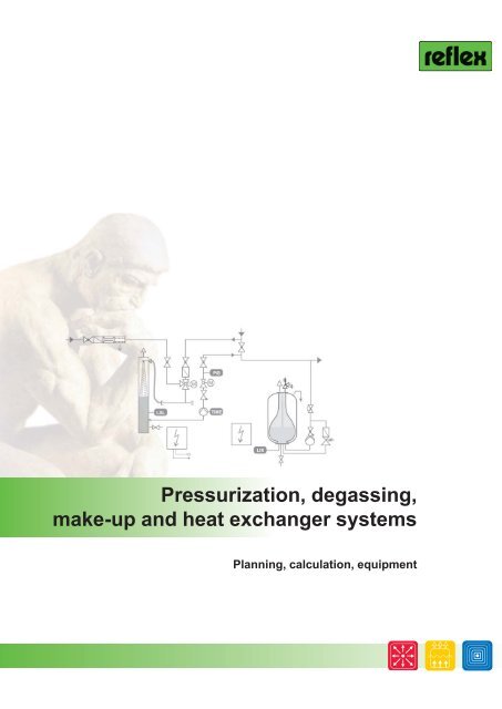
<strong>Pressurization</strong>, degassing,<br />
make-up and heat exchanger <strong>systems</strong><br />
Planning, calculation, equipment
2<br />
Technical planning documentation<br />
’reflex’<br />
Diaphragm Expansion Vessels<br />
for Heating, Solar and Cooling Water Systems<br />
’refix’<br />
Diaphragm Expansion Vessels<br />
for Potable Water Systems<br />
reflex ’reflexomat’<br />
Compressor-Controlled<br />
<strong>Pressurization</strong> Station<br />
reflex ’reflexomat’<br />
Compressor-Controlled<br />
<strong>Pressurization</strong> Station<br />
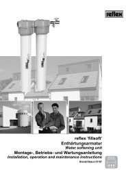
reflex ’fillsoft’<br />
The Water Softening Device<br />
for Your Heating System<br />
Calculate your individual applications on the move -<br />
with our new ’reflex pro app’!<br />
reflex ’variomat’<br />
<strong>Pressurization</strong> Station<br />
with Water Make-Up and Degassing<br />
reflex ’control’<br />
Water Make-Up Systems<br />
reflex ’longtherm’<br />
Brazed Plate Heat Exchangers<br />
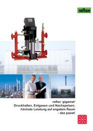
reflex ’gigamat’<br />
<strong>Pressurization</strong> Station<br />
Degassing of Heating and Cooling Systems<br />
Theoretical Principles and<br />
Practical Solutions<br />
reflex ’buffer tanks’<br />
for Hot and Cold Water Storage<br />
reflex Accessories and reflex buffer tanks<br />
- Ideal System Enhancements
Calculation procedures 4<br />
<strong>Pressurization</strong> <strong>systems</strong><br />
Heating and cooling circuits<br />
Role of pressurization <strong>systems</strong> 5<br />
Calculation parameters 5<br />
Properties and auxiliary variables 6<br />
Hydraulic integration 7<br />
Special pressurization <strong>systems</strong> - overview 8<br />
<strong>Reflex</strong> diaphragm expansion vessels 9<br />
Heating <strong>systems</strong> 10 - 11<br />
Solar energy <strong>systems</strong> 12 - 15<br />
Cooling water <strong>systems</strong> 16 - 17<br />
<strong>Reflex</strong> pressurization <strong>systems</strong> with external pressure generation 18 - 22<br />
District heating <strong>systems</strong>, large-scale and special <strong>systems</strong> 23<br />
Potable water <strong>systems</strong><br />
Hot water <strong>systems</strong> 24 - 25<br />
Pressure booster <strong>systems</strong> 24, 26<br />
Make-up and degassing <strong>systems</strong><br />
Water make-up <strong>systems</strong> 27<br />
Degassing stations 28<br />
Research work 29<br />
Water softening <strong>systems</strong> 30 - 33<br />
Heat exchanger <strong>systems</strong><br />
Heat exchangers 34 - 35<br />
Physical principles 36<br />
System equipment 37<br />
Equipment - accessories - safety technology - inspection<br />
Safety valves 38 - 39<br />
Exhaust lines, expansion traps 40<br />
Pressure limiters 41<br />
Expansion lines, shut-off, draining 42<br />
In-line vessels 43<br />
Safety equipment of water heating <strong>systems</strong> 44 - 45<br />
Safety equipment of hot water <strong>systems</strong> 46 - 47<br />
Inspection and maintenance of <strong>systems</strong> and pressure vessels 48 - 51<br />
General information<br />
Terms, code letters, symbols 56<br />
In-house contacts 54<br />
Field sales contacts 55<br />
Contents<br />
3
4<br />
Calculation procedures<br />
Standards,<br />
guidelines<br />
Planning<br />
documentation<br />
Calculation procedures<br />
The aim of this guide is to provide you with the most important information<br />
required to plan, calculate and equip <strong>Reflex</strong> pressurization, degassing and heat<br />
exchanger <strong>systems</strong>. Calculation forms are provided for individual <strong>systems</strong>.<br />
Overviews detail the most important auxiliary variables and properties for calculation<br />
as well as relevant requirements for safety equipment.<br />
Please contact us if you require any additional information.<br />
Your specialist adviser will be happy to help.<br />
The following standards and guidelines contain basic information on planning,<br />
calculation, equipment and operation:<br />
DIN EN 12828 Heating <strong>systems</strong> in buildings – Planning of hot<br />
water heating <strong>systems</strong><br />
DIN 4747 T1 District heating <strong>systems</strong>, safety equipment<br />
DIN 4753 T1 Water heaters and water heating <strong>systems</strong><br />
DIN EN 12976/77 Thermal solar <strong>systems</strong><br />
VDI 6002 (Draft) Solar heating for domestic water<br />
VDI 2035 Part 1 Prevention of damage through scale formation in<br />
domestic hot water and water heating installations<br />
VDI 2035 Part 2 Prevention of damage through water-side<br />
corrosion in water heating installations<br />
EN 13831 Closed expansion vessels with built in diaphragm<br />
for installation in water<br />
DIN 4807 Expansion vessels<br />
DIN 4807 T1 Terms...<br />
DIN 4807 T2 Calculation in conjunction with DIN EN 12828<br />
DIN 4807 T5 Expansion vessels for drinking water installations<br />
DIN 1988 Technical rules for drinking water installations,<br />
pressure increase and reduction<br />
DIN EN 1717 Protection against pollution of potable water<br />
DGRL Pressure Equipment Directive 97/23/EC<br />
BetrSichV Ordinance on Industrial Safety and Health (as of<br />
01/01/2003)<br />
EnEV Energy Saving Ordinance<br />
The product-specific information required for calculations can be found in the<br />
relevant product documents and, of course, at ’www.reflex.de’.<br />
Systems Not all <strong>systems</strong> are covered by the standards, nor is this possible. Based on<br />
new findings, we therefore also provide you with information for the calculation<br />
of special <strong>systems</strong>, such as solar energy <strong>systems</strong>, cooling water circuits, and<br />
district heating <strong>systems</strong>.<br />
With the automation of system operation becoming ever more important, pressure<br />
monitoring and water make-up <strong>systems</strong> are thus also discussed, in addition<br />
to central deaeration and degassing <strong>systems</strong>.<br />
Calculation program Computer-based calculations of pressurization <strong>systems</strong> and heat exchangers<br />
can be performed via our <strong>Reflex</strong> calculation program, which is available for<br />
use or download at www.reflex.de. Another option is to use our new ’reflex<br />
pro app’!<br />
Both tools represent a quick and simple means of finding your ideal solution.<br />
Special <strong>systems</strong> In the case of special <strong>systems</strong>, such as pressurization stations in district heating<br />
<strong>systems</strong> with an output of more than 14 MW or flow temperature over<br />
105°C, please contact our specialist department directly.<br />
Calculation forms<br />
Auxiliary variables<br />
Your specialist adviser<br />
� p. 55<br />
Special pressure<br />
maintenance<br />
+49 2382 7069-536
Role of pressurization <strong>systems</strong><br />
<strong>Pressurization</strong> <strong>systems</strong> play a central role in heating and cooling circuits and perform three main tasks:<br />
1. They keep the pressure within permissible limits at all points of the system, thus ensuring that the<br />
authorized excess operating pressure is maintained while safeguarding a minimum pressure to prevent<br />
vacuums, cavitation and evaporation.<br />
2. They compensate for volume fluctuations of the heating or cooling water as a result of temperature<br />
variations.<br />
3. Provision for system-based water losses by means of a water seal.<br />
Careful calculation, commissioning and maintenance are essential to the correct functioning of the overall system.<br />
Calculation<br />
parameters<br />
Definitions in accordance with DIN EN 12828 and following DIN 4807 T1/T2 based on the example<br />
of a heating system with a diaphragm expansion vessel.<br />
Pressures are given as overpressures and relate to the expansion vessel connection or the pressure<br />
gauge on pressurization stations. The configuration corresponds to the diagram above.<br />
pSV Safety valve actuation pressure<br />
PAZ +<br />
= PLmax Pressure limiter<br />
pf Final pressure<br />
pfil Filling pressure<br />
pi Initial pressure<br />
p0 Minimum operating pressure<br />
= Input pressure for expansion vessel<br />
PAZ = PLmin Minimum pressure limiter<br />
pst Static pressure<br />
PAZ +<br />
tF<br />
Closing pressure<br />
difference acc. to<br />
TRD 721 = ASV<br />
Setpoint value range for<br />
pressure maintenance=<br />
normal pressure level<br />
≥ 0.3 bar<br />
≥ 0.2 bar<br />
+ pe<br />
pSV<br />
0.2<br />
bar<br />
Ve Expansion volume<br />
VWS Water<br />
seal<br />
The permissible excess operating<br />
pressure must not be exceeded at<br />
any point within the system.<br />
Pressure in the system at<br />
maximum temperature<br />
Pressure in the system at<br />
filling temperature<br />
Pressure in the system at<br />
minimum temperature<br />
2. <strong>Pressurization</strong> <strong>systems</strong><br />
2.1. Heating and cooling circuits<br />
Minimum pressure to avoid<br />
- Vacuum formation<br />
- Evaporation<br />
- Cavitation<br />
Pressure of liquid column based on<br />
static height (H)<br />
pf<br />
pfil, pi<br />
p0<br />
PAZ<br />
tR<br />
pst, H<br />
Most common<br />
configuration:<br />
Circulating pump in<br />
advance<br />
Expansion vessel in<br />
return<br />
=<br />
suction pressure<br />
maintenance<br />
PLmax required in accordance<br />
with DIN EN 12828<br />
if individual boiler output<br />
> 300 kW<br />
Normal pressure range<br />
= Pressure maintenance<br />
setpoint value between<br />
pi and pf<br />
Water seal VWS<br />
to cover system-related<br />
water losses<br />
PLmin acc. to DIN EN 12828;<br />
to ensure p0 in hot water<br />
<strong>systems</strong>, an automatic<br />
water make-up system is<br />
recommended,<br />
along<br />
with an<br />
optional minimum<br />
pressure limiter.<br />
5
6<br />
<strong>Pressurization</strong> <strong>systems</strong><br />
Heating and cooling circuits<br />
Properties and auxiliary variables<br />
Properties of water and water mixtures<br />
Pure water without antifreeze additive<br />
t / °C 0 10 20 30 40 50 60 70 80 90 100 105 110 120 130 140 150 160<br />
n / %<br />
(+ 10°C of t) 0 0.13 0.37 0.72 1.15 1.66 2.24 2.88 3.58 4.34 4.74 5.15 6.03 6.96 7.96 9.03 10.20<br />
pe / bar -0.99 -0.98 -0.96 -0.93 -0.88 -0.80 -0.69 -0.53 -0.30 0.01 0.21 0.43 0.98 1.70 2.61 3.76 5.18<br />
∆n (tR) 0 0.64 1.34 2.10 2.50 2.91 3.79<br />
ρ / kg/m³ 1000 1000 998 996 992 988 983 978 972 965 958 955 951 943 935 926 917 907<br />
Water with antifreeze additive* 20% (vol.)<br />
Lowest permissible system temperature -10°C<br />
t / °C 0 10 20 30 40 50 60 70 80 90 100 105 110 120 130 140 150 160<br />
n* / %<br />
(- 10°C of t) 0.07 0.26 0.54 0.90 1.33 1.83 2.37 2.95 3.57 4.23 4.92 --- 5.64 6.40 7.19 8.02 8.89 9.79<br />
pe* / bar -0.9 -0.8 -0.7 -0.6 -0.4 -0.1 --- 0.33 0.85 1.52 2.38 3.47 4.38<br />
ρ / kg/m³ 1039 1037 1035 1031 1026 1022 1016 1010 1004 998 991 --- 985 978 970 963 955 947<br />
Water with antifreeze additive* 34% (vol.)<br />
Lowest permissible system temperature - 20°C<br />
t / °C 0 10 20 30 40 50 60 70 80 90 100 105 110 120 130 140 150 160<br />
n* / %<br />
(- 20 °C of t) 0.35 0.66 1.04 1.49 1.99 2.53 3.11 3.71 4.35 5.01 5.68 --- 6.39 7.11 7.85 8.62 9.41 10.2<br />
pe* / bar -0.9 -0.8 -0.7 -0.6 -0.4 -0.1 --- 0.23 0.70 1.33 2.13 3.15 4.41<br />
ρ / kg/m³ 1066 1063 1059 1054 1049 1043 1037 1031 1025 1019 1012 --- 1005 999 992 985 978 970<br />
n - Percentage expansion for water based on a minimum system temperature of +10°C (generally filling water)<br />
n* - Percentage expansion for water with antifreeze additive* based on a minimum system temperature of -10°C or -20°C<br />
��� - Percentage expansion for water for calculation of temperature layer containers between 70°C and max. return temperature<br />
pe - Evaporation pressure for water relative to atmosphere<br />
pe* - Evaporation pressure for water with antifreeze additive<br />
�� - Density<br />
* - Antifreeze Antifrogen N; when using other antifreeze additives, the relevant properties must be obtained from the manufacturer<br />
Approximate calculation of water content Vs of heating <strong>systems</strong><br />
Vs = Qtot x vs + pipelines + other � for <strong>systems</strong> with natural circulation boilers<br />
Vs = Qtot (vs - 1.4 l) + pipelines + other � for <strong>systems</strong> with heat exchangers<br />
Vs = Qtot (vs - 2.0 l) + pipelines + other � for <strong>systems</strong> without heat exchangers<br />
Vs =<br />
Installed heating output<br />
+ + = liters<br />
Specific water content vs in liters/kW of heating <strong>systems</strong> (heat exchangers, distribution, heating surfaces)<br />
tF/tR<br />
°C<br />
Cast iron<br />
radiators<br />
Radiators<br />
Tube and steel<br />
radiators<br />
Plates Convectors Ventilation<br />
Floor heating<br />
60/40 27.4 36.2 14.6 9.1 9.0<br />
70/50 20.1 26.1 11.4 7.4 8.5<br />
70/55<br />
80/60<br />
19.6<br />
16.0<br />
25.2<br />
20.5<br />
11.6<br />
9.6<br />
7.9<br />
6.5<br />
10.1<br />
8.2<br />
Vs = 20 l/kW<br />
90/70<br />
105/70<br />
13.5<br />
11.2<br />
17.0<br />
14.2<br />
8.5<br />
6.9<br />
6.0<br />
4.7<br />
8.0<br />
5.7<br />
Vs** = 20 l/kW<br />
110/70 10.6 13.5 6.6 4.5 5.4<br />
100/60 12.4 15.9 7.4 4.9 5.5<br />
** If the floor heating is operated and protected as part of the overall system with lower flow<br />
temperatures, vs** must be used to calculate the total water volume<br />
nFH = percentage expansion based on the max. flow temperature of the floor heating<br />
Approx. water content of heating pipes<br />
DN 10 15 20 25 32 40 50 60 65 80 100 125 150 200 250 300<br />
Liters/m 0.13 0.21 0.38 0.58 1.01 1.34 2.1 3.2 3.9 5.3 7.9 12.3 17.1 34.2 54.3 77.9<br />
nFH<br />
n<br />
Caution:<br />
approximate values;<br />
significant deviations<br />
possible in individual<br />
cases.
Hydraulic integration<br />
The hydraulic integration of pressure maintenance in the overall<br />
system greatly influences the pressure profile. This is made up<br />
of the normal pressure level of the pressure maintenance and<br />
the differential pressure generated when the circulating pump is<br />
running. Three main types of pressure maintenance are distinguished,<br />
although additional variants exist in practice.<br />
Input pressure maintenance (suction pressure maintenance)<br />
The pressure maintenance is integrated before the circulating<br />
pump, i.e. on the suction side. This method is used almost<br />
exclusively since it is the easiest to manage.<br />
pSV<br />
Follow-up pressure maintenance The pressure maintenance is integrated after the circulating<br />
pump, i.e. on the pressure side. When calculating the<br />
normal pressure, a system-specific differential pressure share<br />
of the circulating pump (50 ... 100%) must be included. This<br />
method is restricted to a limited number of applications ��solar<br />
energy <strong>systems</strong>.<br />
pSV<br />
Medium pressure maintenance The measuring point of the normal pressure level is<br />
“moved” into the system by means of an analogy measurement<br />
section. The normal and operating pressure levels can<br />
be perfectly coordinated in a variable manner (symmetrical,<br />
asymmetrical medium pressure maintenance). Due to the technically<br />
demanding nature of this method, its use is restricted to<br />
<strong>systems</strong> with complicated pressure ratios, mainly in the field of<br />
district heating.<br />
pSV<br />
psup<br />
�pP<br />
pi, pf<br />
pi, pf<br />
�pP<br />
pi, pf<br />
���<br />
psup<br />
<strong>Reflex</strong> recommendation Use suction pressure maintenance! A different method<br />
should only be used in justified exceptional cases.<br />
Contact us for more information!<br />
psup<br />
pper<br />
pper<br />
pper<br />
�pP<br />
Operating<br />
pressure<br />
ASV<br />
pper<br />
pSV<br />
ASV<br />
pf<br />
Normal pressure setpoint value<br />
pi<br />
p0, psup<br />
Operating<br />
pressure<br />
Operating<br />
pressure<br />
Normal pressure<br />
setpoint value<br />
ASV<br />
Normal pressure<br />
setpoint value<br />
ASV<br />
ASV<br />
pSV, pper<br />
pf<br />
pi<br />
p0<br />
psup<br />
pSV, pper<br />
pf<br />
pi<br />
p0<br />
psup<br />
Advantages:<br />
- Low normal pressure<br />
level<br />
- Operating pressure<br />
> normal pressure,<br />
thus no risk of vacuum<br />
formation<br />
Disadvantages:<br />
- High operating pressure<br />
in the case of<br />
high circulating pump<br />
pressure (large-scale<br />
<strong>systems</strong>); pper must<br />
be observed<br />
Advantages:<br />
- Low normal pressure<br />
level, provided the full<br />
pump pressure is not<br />
required<br />
Disadvantages:<br />
- High normal pressure<br />
level<br />
- Increased need to<br />
observe the required<br />
supply pressure psup for<br />
the circulating pump<br />
according to manufacturer<br />
specifications<br />
Advantages:<br />
- Optimized, variable<br />
coordination of operating<br />
and normal<br />
pressure<br />
Disadvantages:<br />
- Highly demanding<br />
with regard to system<br />
technology<br />
7
8<br />
<strong>Pressurization</strong> <strong>systems</strong><br />
Heating and cooling circuits<br />
Special pressurization <strong>systems</strong> - overview<br />
<strong>Reflex</strong> manufactures two different types of pressurization system:<br />
<strong>Reflex</strong> diaphragm expansion vessels with gas cushions can function without auxiliary<br />
energy and are thus also classed as static pressurization <strong>systems</strong>. The pressure is created<br />
by a gas cushion in the vessel. To enable automatic operation, the system is ideally<br />
combined with reflex ’magcontrol’ make-up stations as well as reflex ’servitec’ make-up<br />
and degassing stations.<br />
<strong>Reflex</strong> pressurization <strong>systems</strong> with external pressure generation require auxiliary<br />
energy and are thus classed as dynamic pressurization <strong>systems</strong>. A differentiation is<br />
made between pump- and compressor-controlled <strong>systems</strong>. While reflex ’variomat’ and<br />
reflex ’gigamat’ control the system pressure directly on the water side using pumps and<br />
overflow valves, the pressure in reflex ’minimat’ and ’reflexomat’ <strong>systems</strong> is controlled on<br />
the air side by means of a compressor and solenoid valve.<br />
Both <strong>systems</strong> have their own advantages. Water-controlled <strong>systems</strong>, for example, are very<br />
quiet and react very quickly to changes in pressure. Thanks to the unpressurized storage of<br />
the expansion water, such <strong>systems</strong> can also be used as central deaeration and degassing<br />
units (’variomat’). Compressor-controlled <strong>systems</strong>, such as ’reflexomat’, offer extremely<br />
flexible operation within the tightest pressure limits, specifically within ± 0.1 bar (pumpcontrolled<br />
approx. ± 0.2 bar) of the setpoint value.<br />
A degassing function can also be implemented in this case in combination with reflex<br />
’ servitec’.<br />
Our <strong>Reflex</strong> calculation program will help you identify the ideal solution.<br />
Preferred applications are detailed in the following table. Based on experience, we<br />
recommend that the pressure maintenance be automated – i.e. pressure monitoring<br />
with timely water make-up – and that <strong>systems</strong> be automatically and centrally vented.<br />
This eliminates the need for conventional air separators and laborious post-venting, while<br />
ensuring safer operation and lower costs<br />
’reflex’ expansion<br />
vessel<br />
’variomat’<br />
’gigamat’<br />
’minimat’<br />
’reflexomat’<br />
Standard pressure<br />
maintenance<br />
Flow temp. up to 120°C<br />
- Without additional equipment<br />
- With ’control’ make-up<br />
- With ’servitec’<br />
1 Single-pump system<br />
2-1 Single-pump system<br />
2-2 Dual-pump system<br />
- Without additional equipment<br />
- With ’servitec’<br />
Pressure<br />
maint.<br />
X<br />
X<br />
X<br />
X<br />
X<br />
X<br />
X<br />
X<br />
Autom.<br />
operation<br />
with makeup<br />
---<br />
X<br />
X<br />
X<br />
X<br />
X<br />
X<br />
X<br />
Central<br />
deaeration<br />
and<br />
degassing<br />
---<br />
---<br />
X<br />
X<br />
X<br />
X<br />
X*<br />
X<br />
- Special <strong>systems</strong> As required<br />
- Without additional equipment<br />
- With ’control’ make-up<br />
- With ’servitec’<br />
- Without additional equipment<br />
- With ’control’ make-up<br />
- With ’servitec’<br />
X<br />
X<br />
X<br />
X<br />
X<br />
X<br />
---<br />
X<br />
X<br />
---<br />
X<br />
X<br />
---<br />
---<br />
X<br />
---<br />
---<br />
X<br />
Preferred output<br />
range<br />
Up to 1,000 kW<br />
150 - 2,000 kW<br />
150 - 4,000 kW<br />
500 - 8,000 kW<br />
5,000 - 60,000 kW<br />
100 - 2,000 kW<br />
150 - 24,000 kW<br />
’Degassing of heating<br />
and cooling <strong>systems</strong>’<br />
This brochure explains<br />
when and why the use<br />
of degassing <strong>systems</strong><br />
is required, particularly<br />
in closed <strong>systems</strong>.<br />
* In the case of return temperatures < 70°C, refl ex ’gigamat’ can also be used for degassing purposes without additional equipment
Vn<br />
Nominal volume Vn<br />
Ve + VWS<br />
Pressure monitoring<br />
Input pressure p0<br />
Minimum operating<br />
pressure<br />
Initial pressure pa<br />
Water make-up<br />
<strong>Reflex</strong> diaphragm expansion vessels<br />
types: ’reflex N, F, S, G’<br />
The pressure in the expansion vessel is generated by a gas cushion. The<br />
water level and pressure in the gas space are linked (p x V = constant).<br />
Therefore, it is not possible to use the entire nominal volume for water<br />
intake purposes. The nominal volume is greater than the water intake<br />
pf volume Ve + VWS by a factor of + 1 .<br />
pf - p0<br />
This is one reason why dynamic pressurization <strong>systems</strong> are preferable in<br />
the case of larger <strong>systems</strong> and small pressure ratios (pf - p0). When using<br />
reflex ’servitec’ degassing <strong>systems</strong>, the volume of the degassing pipe (5<br />
liters) must be taken into account during sizing.<br />
The gas input pressure must be manually checked before commissioning<br />
and during annual maintenance work; it must be set to the minimum<br />
operating pressure of the system and entered on the name plate. The<br />
planner must specify the gas input pressure in the design documentation.<br />
To avoid cavitation on the circulating pumps, we recommend that<br />
the minimum operating pressure not be set to less than 1 bar, even in the<br />
case of roof-mounted <strong>systems</strong> and heating <strong>systems</strong> in low-rise buildings.<br />
The expansion vessel is usually integrated on the suction side of the<br />
circulating pump (input pressure maintenance). In the case of pressureside<br />
integration (follow-up pressure maintenance) the differential pressure<br />
of the circulating pumps �pP must be taken into account to avoid<br />
vacuum formation at high points.<br />
When calculating p0, we recommend the addition of 0.2 bar safety margin.<br />
This margin should only be dispensed with in the case of very small<br />
pressure ratios.<br />
This is one of the most important pressures! It limits the lower setpoint<br />
value range of the pressure maintenance and safeguards the water<br />
seal VWS, that is the minimum water level in the expansion vessel.<br />
Accurate checking and monitoring of the input pressure is only ensured<br />
if the <strong>Reflex</strong> formula for the input pressure is followed. Our calculation<br />
program takes this into account. With these higher input pressures<br />
compared to traditional configurations (larger water seal), stable operation<br />
is assured. Known problems with expansion vessels caused by an<br />
insufficient or even missing water seal are thus avoided. Particularly in<br />
the case of small differences between the final pressure and input pressure,<br />
the new calculation method can result in somewhat larger vessels.<br />
However, in terms of enhanced operational safety, the difference is<br />
insignificant.<br />
reflex ’control’ make-up stations automatically monitor and secure the<br />
initial or filling pressure. � reflex ’control’ make-up stations<br />
Filling pressure pfil The filling pressure pfil is the pressure that must be applied, relative to<br />
the temperature of the filling water, to fill a system such that the water<br />
seal VWS is maintained at the lowest system temperature. In the case of<br />
heating <strong>systems</strong>, the filling pressure and initial pressure are generally<br />
the same (lowest system temperature = filling temperature = 10°C). In<br />
cooling circuits with temperatures below 10°C, for instance, the filling<br />
pressure is higher than the initial pressure.<br />
Final pressure pf The final pressure restricts the upper setpoint value range of the pressure<br />
maintenance. It must be set such that the pressure on the system<br />
safety valve is lower by at least the closing pressure difference ASV in<br />
accordance with TRD 721. The closing pressure difference depends on<br />
the type of the safety valve.<br />
Degassing<br />
Deaeration<br />
Targeted venting is very important, particularly in the case of closed<br />
<strong>systems</strong>; otherwise, accumulations of nitrogen in particular can lead to<br />
troublesome malfunctions and customer dissatisfaction. reflex ’servitec’<br />
degases and makes up water automatically. � p. 28<br />
Without degassing<br />
pf + 1<br />
Vn = (Ve + VWS)<br />
pf - p0<br />
With reflex ’servitec’<br />
pf + 1<br />
Vn = (Ve + VWS + 5 l) pf - p0<br />
Input pressure maintenance<br />
p0 � pst + pe + 0.2 bar<br />
p0 � 1 bar <strong>Reflex</strong> recommendation<br />
Follow-up pressure maintenance<br />
p0 � pst + pe + ∆pP<br />
<strong>Reflex</strong> formula for initial<br />
pressure<br />
pi � p0 + 0.3 bar<br />
<strong>Reflex</strong> recommendation<br />
pf = pSV - ASV<br />
9<br />
pSV � p0 + 1.5 bar<br />
for pSV ≤ 5 bar<br />
pSV ≥ p0 + 2.0 bar<br />
for pSV > 5 bar<br />
Closing pressure difference<br />
acc. to TRD 721 ASV<br />
SV-H 0.5 bar<br />
SV-D/G/H 0.1 pSV<br />
0.3 bar for<br />
pSV < 3 bar
10<br />
<strong>Pressurization</strong> <strong>systems</strong><br />
Heating and cooling circuits<br />
Heating <strong>systems</strong><br />
Calculation According to DIN 4807 T2 and DIN EN 12828<br />
Configuration Usually in the form of suction pressure maintenance as per adjacent<br />
diagram with circulating pump in advance and expansion vessel in return<br />
– i.e. on the suction side of the circulating pump<br />
Properties n, pe Generally properties for pure water without antifreeze additive � page 6<br />
Expansion volume Ve Calculation of percentage expansion, usually between lowest temperature<br />
Highest temperature tTR = filling temperature = 10°C and highest setpoint value adjustment of temperature<br />
regulator tTR<br />
Minimum operating pres- Particularly in the case of low-rise buildings and roof-mounted <strong>systems</strong>,<br />
sure p0 the low static pressure pst requires that the minimum supply pressure for<br />
the circulating pump be verified on the basis of manufacturer specifications.<br />
Even with lower static heights, we therefore recommend that the<br />
minimum operating pressure p0 not be set to less than 1 bar.<br />
Filling pressure pfil Since a filling temperature of 10°C generally equates to the lowest system<br />
Initial pressure pa temperature, the filling pressure and input pressure of an expansion vessel<br />
are identical.<br />
In the case of pressurization <strong>systems</strong>, it should be noted that filling and<br />
make-up <strong>systems</strong> may have to operate at a level approaching the final<br />
pressure. This only applies to ’reflexomat’.<br />
Pressure maintenance In the form of static pressure maintenance with ’reflex N, F, S, G’ also in<br />
combination with the make-up and degassing stations ’control’ and ’servitec’,<br />
or from approx. 150 kW as a ’variomat’ pressurization station for<br />
pressure maintenance, degassing and water make-up, or in the form of a<br />
compressor-controlled ’reflexomat’ pressurization station. ��page 18<br />
In <strong>systems</strong> with oxygen-rich water (e.g. floor heating with non-diffusionresistant<br />
pipes), ’refix D’, ’refix DE’ or ’refix DE junior’ are used up to 70°C<br />
(all water-carrying parts corrosion-resistant).<br />
Degassing, deaeration, To ensure ongoing safe and automatic operation of the heating system,<br />
water make-up the pressurization units should be equipped with make-up <strong>systems</strong> and<br />
supplemented with ’servitec’ degassing <strong>systems</strong>. More information can be<br />
found on page 28.<br />
In-line vessels If a temperature of 70°C is permanently exceeded by the pressure maintenance,<br />
an in-line vessel must be installed to protect the diaphragms in<br />
the expansion vessel. → page 43<br />
Individual protection According to DIN EN 12828, all heat generators must be connected to<br />
at least one expansion vessel. Only protected shut-offs are permitted. If<br />
a heat generator is shut off hydraulically (e.g. in-line boiler circuits), the<br />
connection with the expansion vessel must remain intact. Therefore, in the<br />
case of multi-boiler <strong>systems</strong>, each boiler is usually secured with a separate<br />
expansion vessel. This is only included in the calculation for the relevant<br />
boiler water content.<br />
Due to the excellent degassing performance<br />
of ’variomat’, we recommend that the switch<br />
frequency be minimized by also fitting a diaphragm<br />
expansion vessel (e.g. ’reflex N’) to<br />
the heat generator in this case.<br />
’reflex’<br />
’variomat’<br />
’gigamat’<br />
’reflexomat’<br />
Caution with roof-mounted<br />
<strong>systems</strong> and low-rise<br />
buildings<br />
<strong>Reflex</strong> recommendation:<br />
p0 ≥ 1 bar<br />
In the case of corrosion<br />
risk, use ’refix’
’reflex N, F, G’ in heating <strong>systems</strong><br />
Configuration Input pressure maintenance, expansion vessel in return, circulating pump in<br />
advance, observe information on page 9 for follow-up pressure maintenance.<br />
Object:<br />
Initial data<br />
Heat generator 1 2 3 4<br />
Heat output Qh = .......... kW .......... kW .......... kW .......... kW Qtot = .......... kW<br />
Water content VW = .......... liters<br />
System flow temperature<br />
System return temperature<br />
Water content known<br />
tF<br />
tR<br />
Vs<br />
= .......... °C<br />
→ p. 6 Approximate water content<br />
= .......... °C<br />
vs = f (tF, tR, Q)<br />
= .......... liters<br />
Vs = .......... liters<br />
Highest setpoint value adjustment<br />
Temperature regulator tTR<br />
Antifreeze additive<br />
= .......... °C<br />
= .......... %<br />
→ p. 6 Percentage expansion n<br />
(with antifreeze additive n*)<br />
n = .......... %<br />
Safety temperature limiter tSTL = .......... °C<br />
→ p. 6 Evaporation pressure pe at > 100°C<br />
with antifreeze additive pe*)<br />
pe = .......... bar<br />
Static pressure pst = .......... bar pst = .......... bar<br />
Pressure calculation<br />
Input pressure p0 = stat. pressure pst + evaporation pressure pe + (0.2 bar) 1)<br />
p0 = ....................... +.......................................+ (0.2 bar) 1) = ............. bar<br />
<strong>Reflex</strong> recommendation p0 ≥ 1.0 bar<br />
Safety valve actuation pSV → <strong>Reflex</strong> recommendation<br />
pressure pSV ≥ input pressure p0 + 1.5 bar for pSV ≤ 5 bar<br />
pSV ≥ input pressure p0 + 2.0 bar for pSV > 5 bar<br />
pSV ≥ ....................... +......................................................... = ............. bar<br />
Final pressure pf ≤ safety valve pSV - closing pressure difference acc. to TRD 721<br />
pf ≤ pSV - 0.5 bar for pSV ≤ 5 bar<br />
pf ≤ pSV - 0.1 x pSV for pSV > 5 bar<br />
pf ≤ ................................ - ............................................... = ............. bar<br />
Vessel<br />
p0 = .......... bar<br />
pSV = .......... bar<br />
pf = .......... bar<br />
Expansion volume Ve =<br />
n<br />
100<br />
x Vs = ...................... x ............................. = .......... liters Ve = ......... liters<br />
Water seal VWS = 0.005x Vs for Vn > 15 liters with VWS ≥ 3 liters<br />
VWS ≥ 0.2 x Vn for Vn ≤ 15 liters<br />
VWS = ......... liters<br />
VWS ≥ ..........x .... = ...................... x ............................. = .......... liters<br />
Nominal volume<br />
Without ’servitec’ Vn = (Ve + VWS) x<br />
pf +1<br />
With ’servitec’ Vn = (Ve + VWS + 5 liters) x<br />
Vn ≥ ............................. x ............................................ = .......... liters<br />
Selected Vn ’reflex’ = .......... liters<br />
Initial pressure check<br />
pf<br />
Without ’servitec’ pi =<br />
+ 1<br />
- 1 bar<br />
Ve (pf + 1)(n + nR)<br />
1+<br />
Vn (p0 + 1) 2n<br />
pf<br />
With ’servitec’ pi =<br />
+ 1<br />
- 1 bar<br />
(Ve + 5 liters)(pf + 1) (n + nR)<br />
1+<br />
Vn (p0 + 1) 2n<br />
pi =<br />
...............................<br />
- 1 bar = ............. bar<br />
...........................<br />
1+<br />
...........................<br />
Condition: pi ≥ p0 + 0.25...0.3 bar, otherwise calculation for greater nominal volume<br />
Result summary<br />
pf - p0<br />
pf +1<br />
pf - p0<br />
’reflex ...’ / ... bar ........... liters Input pressure p0 = ......... bar → check before commissioning<br />
’refix ...’ / ... bar ........... liters Initial pressure pi = ......... bar → check make-up configuration<br />
’refix’ only for oxygen-rich water Final pressure pf = ......... bar<br />
(e.g. floor heating)<br />
Vn = ......... liters<br />
pi = .......... bar<br />
’reflex’<br />
Diaphragm Expansion Vessels<br />
for Heating, Solar and Cooling Water Systems<br />
If R > 70°C,<br />
’V in-line vessel’<br />
required<br />
1) Recommendation<br />
Check rec. supply pressure<br />
of circulation pump<br />
as per manufacturer<br />
specifications<br />
Check compliance<br />
with perm. operating<br />
pressure<br />
11<br />
Filling pressure<br />
=<br />
Initial pressure<br />
at 10°C filling<br />
temperature
12<br />
<strong>Pressurization</strong> <strong>systems</strong><br />
Heating and cooling circuits<br />
Solar heating plants (solar energy <strong>systems</strong>)<br />
Calculation On the basis of VDI 6002 and DIN 4807 T2<br />
In the case of solar heating plants, the highest temperature cannot be<br />
defined via the regulator on the heat generator, but instead is determined by<br />
the stagnation temperature on the collector. This gives rise to two possible<br />
calculation methods.<br />
Nominal volume Calculation without evaporation in the collector<br />
The percentage expansion n* and evaporation pressure pe* are based on<br />
the stagnation temperature. Since some collectors can reach temperatures<br />
of over 200°C, this calculation method cannot be applied here. In the case<br />
of indirectly heated tube collectors (heat pipe system), it is possible for <strong>systems</strong><br />
to restrict the stagnation temperature. If a minimum operating pressure<br />
of p0 ≤ 4 bar is sufficient to prevent evaporation, the calculation can usually<br />
be performed without taking evaporation into account.<br />
With this option, it should be noted that an increased temperature load will<br />
impact the antifreeze effect of the heat transfer medium in the long term.<br />
Nominal volume Calculation with evaporation in the collector<br />
For collectors with stagnation temperatures in excess of 200°C, evaporation<br />
in the collector cannot be excluded. In this case, the evaporation pressure<br />
is only included in the calculation up to the desired evaporation point (110 -<br />
120°C). When calculating the nominal volume of the expansion vessel, the<br />
entire collector volume VC is included in addition to the expansion volume<br />
Ve and the water seal VWS.<br />
This is the preferred option, as the lower temperature has a lesser impact<br />
on the heat transfer medium and the antifreeze effect is maintained for a<br />
longer period.<br />
Direct heating in a flat<br />
collector or direct-flow<br />
tube collector<br />
RL<br />
VC<br />
SL<br />
Indirect heating in a tube<br />
collector according to the<br />
heat pipe principle<br />
RL<br />
SL<br />
VC<br />
Heat pipe<br />
Note manufacturer<br />
specifications<br />
for stagnation<br />
temperatures!<br />
Nominal volume without<br />
evaporation<br />
pf + 1<br />
Vn = (Ve + VWS)<br />
pf - p0<br />
Nominal volume with<br />
evaporation<br />
pf + 1<br />
Vn = (Ve + VWS + VC)<br />
pf - p0
Configuration Since the expansion vessel with safety valve in the return must be installed<br />
such that it cannot be shut off from the collector, this inevitably leads to<br />
follow-up pressure maintenance, i.e. integration of the expansion vessel on<br />
the pressure side of the circulating pump.<br />
Properties n*, pe* When determining the percentage expansion n* and the evaporation pressure<br />
pe*, antifreeze additives of up to 40% must be taken into account in<br />
accordance with manufacturer specifications.<br />
→ p. 6, properties for water mixtures with Antifrogen N<br />
Input pressure p0<br />
Minimum operating<br />
pressure<br />
Filling pressure pfil<br />
Initial pressure pa<br />
If calculating with evaporation, the evaporation pressure pe* is included up<br />
to the boiling temperature 110°C or 120°C. The percentage expansion n* is<br />
then determined between the lowest ambient temperature (e.g. -20°C) and<br />
the boiling temperature.<br />
If calculating without evaporation, the evaporation pressure pe* and the<br />
percentage expansion n* must be based on the stagnation temperature of<br />
the collector.<br />
Depending on the calculation method employed, the minimum operating<br />
pressure (= input pressure) is adapted to the stagnation temperature<br />
in the collector (= without evaporation) or the boiling temperature (= with<br />
evaporation). In both cases, the normal configuration of the circulating pump<br />
pressure ∆pP must be taken into account since the expansion vessel is<br />
integrated on the pressure side of the circulating pump (follow-up pressure<br />
maintenance).<br />
As a rule, the filling temperature (10°C) is much higher than the lowest<br />
system temperature, such that the filling pressure is greater than the initial<br />
pressure.<br />
Pressure maintenance Generally in the form of static pressure maintenance with ’reflex S’, also in<br />
combination with ’magcontrol’ make-up stations.<br />
In-line vessels If a stable return temperature ≤ 70°C cannot be guaranteed on the consumer<br />
side, an in-line vessel must be fitted to the expansion vessel. → p. 39<br />
’reflex S’<br />
With evaporation<br />
pe* = 0<br />
n* = f (boiling temp.)<br />
Without evaporation<br />
pe* = f (stagnation temp.)<br />
n* = f (stagnation temp.)<br />
Without evaporation<br />
p0 = pst + pe*(stagnation) + ∆pP<br />
With evaporation<br />
p0 = pst + pe*(boiling) + ∆pP<br />
Enter set input pressure<br />
on name plate<br />
13
14<br />
<strong>Pressurization</strong> <strong>systems</strong><br />
Heating and cooling circuits<br />
reflex ’S’ in solar energy <strong>systems</strong> with evaporation<br />
Calculation method: The minimum operating pressure p0 is calculated such that no<br />
evaporation occurs up to flow temperatures of 110°C or 120°C<br />
– i.e. evaporation is permitted in the collector at stagnation<br />
temperature.<br />
Configuration Follow-up pressure maintenance, expansion vessel in return to collector.<br />
Object:<br />
Initial data<br />
Number of collectors z .......... units<br />
Collector surface area AC .......... m² ACtot = z x AC ACtot = .......... m² ACtot = ......... bar<br />
Water content per collector VC ......... liters VCtot = z x AC VCtot = .......... liters VCtot = ......... liters<br />
Highest flow temperature tF<br />
Lowest ambient temperature ta<br />
Antifreeze additive<br />
110°C or 120°C<br />
- 20°C<br />
.......... %<br />
→ p. 6 Percentage expansion n* and<br />
evaporation pressure pe*<br />
n* = .......... %<br />
pe* = .......... bar<br />
Static pressure pst .......... bar pst = .......... bar<br />
Difference at circulating<br />
pump<br />
∆pP .......... bar<br />
∆pP = .......... bar<br />
Pressure calculation<br />
Input pressure p0 = stat. pressure pst + pump pressure ∆pP + evaporation pressure pe*<br />
p0 = ........................... + .............................. + ....................................<br />
= .......... bar<br />
p0 = .......... bar<br />
Safety valve actuation pSV → <strong>Reflex</strong> recommendation<br />
pressure pSV ≥ input pressure p0 + 1.5 bar for pSV ≤ 5 bar<br />
pSV ≥ input pressure p0 + 2.0 bar for pSV > 5 bar<br />
pSV ≥ .................. + ............................................ = .......... bar<br />
pSV = .......... bar<br />
Final pressure pf ≤ safety valve pSV – Closing pressure difference acc. to TRD 721<br />
pf<br />
pf<br />
≤ pSV<br />
≤ pSV<br />
– 0.5 bar for pSV ≤ 5 bar<br />
– 0.1 bar x pSV > 5 bar<br />
pf = .......... bar<br />
pf ≤ .............................. – ................................. = .......... bar<br />
Vessel<br />
System volume Vs<br />
Vs<br />
= collector vol. VCtot + pipelines + buffer tank + other<br />
= ............................ + .............. + ................ + ................<br />
= .......... liters<br />
Vs = ......... liters<br />
Expansion<br />
volume<br />
Ve =<br />
n*<br />
100<br />
x Vs = ...................... + .................. = .......... liters Ve = ......... liters<br />
Water seal VWS = 0.005 x Vs for Vn > 15 liters with VWS ≥ 3 liters<br />
VWS ≥ 0.2 x Vn for Vn ≤ 15 liters<br />
VWS = ......... liters<br />
VWS ≥ .......... x .... = ........... x .................. = .......... liters<br />
Nominal volume<br />
Vn = (Ve + VWS + VCtot )<br />
pf +1<br />
x<br />
pf - p0<br />
Vn = ......... liters<br />
Vn ≥ ............................. x ................................. = .......... liters<br />
Selected Vn ’reflex S’ = .......... liters<br />
Check of<br />
initial pressure pi<br />
pi<br />
=<br />
=<br />
pf + 1<br />
(Ve + VCtot)(pf + 1)<br />
1 +<br />
Vn (p0 + 1)<br />
...............................<br />
..........................<br />
1 +<br />
...........................<br />
– 1 bar<br />
– 1 bar = .......... bar<br />
pi = .......... bar<br />
Condition: pi ≥ p0 + 0.25...0.3 bar, otherwise calculation for greater nominal volume<br />
Percentage expansion Between lowest temperature (- 20°C) and filling temperature (usually 10°C)<br />
→ p. 6 n*F = .......... %<br />
Filling pressure<br />
pfil = Vn x<br />
p0 +1<br />
Vn - Vs x nF* - VWS<br />
– 1 bar<br />
pfil = ............................. x ..................... – 1 bar = .......... liters<br />
n*F = .......... %<br />
pfil = .......... bar<br />
Result summary<br />
’reflex S’/10 bar ........... liters Input pressure p0 = ......... bar → check before commissioning<br />
Initial pressure pi = ......... bar → check make-up configuration<br />
Filling pressure pfil = ......... bar → refilling of system<br />
Final pressure pf = ......... bar<br />
’reflex’<br />
Diaphragm Expansion Vessels<br />
for Heating, Solar and Cooling Water Systems<br />
Check compliance with<br />
minimum supply pressure<br />
psup for circulating<br />
pumps acc. to manufacturer<br />
specifications.<br />
psup = p0 - ���<br />
Check compliance<br />
with perm. operating<br />
pressure
eflex ’S’ in solar energy <strong>systems</strong> without evaporation<br />
Calculation method: The minimum operating pressure p0 is set such that no<br />
evaporation occurs in the collector – generally possible at<br />
stagnation temperatures ≤ 150°C.<br />
Configuration Follow-up pressure maintenance, expansion vessel in return to collector<br />
Object:<br />
Initial data<br />
Number of collectors z .......... units<br />
Collector surface area AC .......... m² ACtot = z x AC ACtot = .......... m² ACtot = ......... bar<br />
Water content per collector VC ......... liters VCtot = z x AC VCtot = .......... liters VCtot = ......... liters<br />
Highest advance temperature tF<br />
Lowest ambient temperature ta<br />
Antifreeze additive<br />
- 20°C<br />
.......... %<br />
→ p. 6 Percentage expansion n* and<br />
evaporation pressure pe*<br />
n* = .......... %<br />
pe* = .......... bar<br />
Static pressure pst .......... bar pst = .......... bar<br />
Difference at circulating<br />
pump<br />
∆pP .......... bar<br />
∆pP = .......... bar<br />
Pressure calculation<br />
Input pressure p0 = stat. pressure pst + pump pressure ∆pP + evaporation pressure pe*<br />
p0 = ........................... + .............................. + ....................................<br />
= .......... bar<br />
p0 = .......... bar<br />
Safety valve actuation pSV → <strong>Reflex</strong> recommendation<br />
pressure pSV ≥ input pressure p0 + 1.5 bar for pSV ≤ 5 bar<br />
pSV ≥ input pressure p0 + 2.0 bar for pSV > 5 bar<br />
pSV ≥ .................. + .................................................... = .......... bar<br />
pSV = .......... bar<br />
Final pressure pf ≤ safety valve pSV – Closing pressure difference acc. to TRD 721<br />
pf<br />
pf<br />
≤ pSV<br />
≤ pSV<br />
– 0.5 bar for pSV ≤ 5 bar<br />
– 0.1 bar x pSV > 5 bar<br />
pf = .......... bar<br />
pf ≤ .............................. – ................................. = .......... bar<br />
Vessel<br />
System volume Vs = collector vol. VCtot + pipelines + buffer tank + other Vs = ......... liters<br />
Vs = ............................ + ............. + .................. + ................<br />
= .......... liters<br />
Expansion volume Ve =<br />
n*<br />
100<br />
x Vs = ...................... + .................. = .......... liters Ve = ......... liters<br />
Water seal VWS = 0.005 x Vs for Vn > 15 liters with VWS ≥ 3 liters<br />
VWS ≥ 0.2 x Vn for Vn ≤ 15 liters<br />
VWS = ......... liters<br />
VWS ≥ .......... x .... = ........... x .................. = .......... liters<br />
Nominal volume<br />
Vn = (Ve + VWS )<br />
pf +1<br />
x<br />
pf - p0<br />
Vn = ......... liters<br />
Vn ≥ ............................. x ................................. = .......... liters<br />
Selected Vn ’reflex S’ = .......... liters<br />
Check of<br />
initial pressure pi =<br />
1 +<br />
pf + 1<br />
Ve (pf + 1)<br />
Vn (p0 + 1)<br />
– 1 bar<br />
pi<br />
...............................<br />
=<br />
..........................<br />
1 +<br />
...........................<br />
– 1 bar = .......... bar<br />
pi = .......... bar<br />
Condition: pi ≥ p0 + 0.25...0.3 bar, otherwise calculation for greater nominal volume<br />
Percentage expansion Between lowest temperature (- 20°C) and filling temperature (usually 10°C)<br />
→ p. 6 n*F = .......... %<br />
Filling pressure<br />
p0 +1<br />
pfil = Vn x<br />
Vn - Vs x nF* - VWS<br />
– 1 bar<br />
pfil = ............................. x ..................... – 1 bar = .......... liters<br />
n*F = .......... %<br />
pfil = .......... bar<br />
Result summary<br />
’reflex S’/10 bar ........... liters Input pressure p0 = ......... bar → check before commissioning<br />
Initial pressure pi = ......... bar → check make-up configuration<br />
Filling pressure pfil = ......... bar → refilling of system<br />
Final pressure pf = ......... bar<br />
’reflex’<br />
Diaphragm Expansion Vessels<br />
for Heating, Solar and Cooling Water Systems<br />
Check compliance with minimum<br />
supply pressure psup<br />
for circulating pumps acc. to<br />
manufacturer specifications.<br />
psup = p0 - ∆pP<br />
Check compliance<br />
with perm. operating<br />
pressure<br />
15
16<br />
<strong>Pressurization</strong> <strong>systems</strong><br />
Heating and cooling circuits<br />
Cooling water <strong>systems</strong><br />
Calculation On the basis of DIN EN 12828 and DIN 4807 T2<br />
Configuration In the form of input pressure maintenance as per adjacent diagram with<br />
expansion vessel on the suction side of the circulating pump, or in the form<br />
of follow-up pressure maintenance.<br />
Properties n* When determining the percentage expansion n*, antifreeze additives appropriate<br />
for the lowest system temperature must be included in accordance<br />
with manufacturer specifications.<br />
For Antifrogen N → p. 6<br />
Expansion volume Ve Calculation of the percentage expansion n* usually between the lowest<br />
system temperature (e.g. winter downtime: -20°C) and the highest system<br />
temperature (e.g. summer downtime +40°C).<br />
Minimum operating<br />
pressure p0<br />
Filling pressure pfil Initial<br />
pressure pi<br />
Since no temperatures > 100°C are used, no special margins are required.<br />
In many cases, the lowest system temperature is less than the filling temperature,<br />
meaning that the filling pressure is higher than the initial pressure.<br />
Pressure maintenance Generally in the form of static pressure maintenance with ’reflex’, also in<br />
combination with ’control’ and ’servitec’ make-up and degassing stations.<br />
Degassing, deaeration,<br />
water make-up<br />
To ensure ongoing safe and automatic operation in cooling water <strong>systems</strong>,<br />
the pressurization units should be equipped with make-up <strong>systems</strong> and<br />
supplemented with ’servitec’ degassing <strong>systems</strong>. This is particularly important<br />
with cooling water <strong>systems</strong>, since no thermal deaeration effects apply.<br />
More information can be found on page 28.<br />
In-line vessels Although ’reflex’ diaphragms are suitable for temperatures down to -20°C<br />
and vessels to -10°C, the possibility of the diaphragms freezing to the container<br />
cannot be excluded. We therefore recommend the integration of a<br />
’V in-line vessel’ in the return to the refrigerating machine at temperatures<br />
≤ 0°C. → page 39<br />
Individual protection As in the case of heating <strong>systems</strong>, we recommend the use of individual<br />
protection for multiple refrigerating machines.<br />
→ Heating <strong>systems</strong>, p. 10<br />
’reflex’<br />
Enter set input<br />
pressure on name<br />
plate
’reflex N, F, S, G’ in cooling water <strong>systems</strong><br />
Configuration Input pressure maintenance, expansion vessel on suction side, circulating<br />
pump, observe information on page 9 for follow-up pressure maintenance.<br />
Object:<br />
Initial data<br />
Return temperature to refrigerating machinetR = .......... °C<br />
Advance temperature to refrigerating machinetF = .......... °C<br />
Lowest system temperature tSmin = ......... liters (e.g. winter downtime)<br />
Highest system temperature tSmax= ......... liters (e.g. summer downtime)<br />
Antifreeze additive = .......... %<br />
Percentage expansion n* ��������� n* = n* at highest temp. (tSmax or tR) - n* at lowest temp. (tSmin or tF) n* =<br />
.................................... - ............................. = .......... °C<br />
n* = .......... %<br />
Percentage expansion between lowest temperature and filling temperature = .......... °C nF* = .......... %<br />
Static pressure pst = .......... bar pst = .......... bar<br />
Pressure calculation<br />
Input pressure p0 = static pressure pst + (0.2 bar) 1)<br />
p0 = ............................. + (0.2 bar)<br />
p0 = .......... bar<br />
1) = .......... bar<br />
pSV ��<strong>Reflex</strong> recommendation<br />
Safety valve actuation pressure<br />
pSV ≥ input pressure p0 + 1.5 bar for pSV ≤ 5 bar<br />
pSV ≥ input pressure p0 + 2.0 bar for pSV ≤ 5 bar<br />
pSV ≥ ............................. + ................................. = .......... bar<br />
pSV = .......... bar<br />
Final pressure pf ≤ safety valve pSV – Closing pressure difference acc. to TRD 721<br />
pf ≤ pSV<br />
pf ≤ pSV<br />
– 0.5 bar for pSV ≤ 5 bar<br />
– 0.1 bar for pSV ≤ 5 bar<br />
pf = .......... bar<br />
pf ≤ .............................. – ................................. = .......... bar<br />
Vessel<br />
System volume Vs Refrigerating machines: .............. liters<br />
Cooling registers : ................... liters<br />
Buffer tanks : ................... liters<br />
Pipelines : ................... liters<br />
Other : ................... liters<br />
System volume Vs : ................... liters<br />
Expansion volume Ve =<br />
n*<br />
100<br />
x Vs<br />
= .................................. = ..........<br />
liters<br />
Water seal VWS = 0.005x Vs for Vn > 15 liters with VWS ≥ 3 liters<br />
VWS ≥ 0.2 x Vn for Vn ≤ 15 liters<br />
VWS ≥ ......... x ................. = ................................. = .......... liters<br />
Nominal volume<br />
Without ’servitec’ Vn = (Ve + VWS ) x<br />
pf +1<br />
pf - p0<br />
With ’servitec’ Vn = (Ve + VWS + 5 liters ) x<br />
pf +1<br />
Vn ≥ ............................. x .................................. = .......... liters<br />
Selected Vn ’reflex’ = .......... liters<br />
Initial pressure check<br />
Without ’servitec’ pi =<br />
1 +<br />
pf + 1<br />
Ve (pf + 1)<br />
Vn (p0 + 1)<br />
– 1 bar<br />
pf<br />
pi =<br />
+ 1<br />
– 1 bar<br />
(Ve + 5 liters) (pf + 1)<br />
1 +<br />
Vn (p0 + 1)<br />
pi =<br />
...........................<br />
...........................<br />
1 +<br />
...........................<br />
– 1 bar = .......... bar<br />
pi = p0 + 0.25...0.3 bar, otherwise calculation for greater nominal volume<br />
Filling pressure<br />
p0<br />
pfil = Vn x<br />
+1<br />
Vn - Vs x nF* - VWS<br />
– 1 bar<br />
pfil = ............................. x ..................... – 1 bar = .......... liters<br />
Vs = ......... liters<br />
Ve = ......... liters<br />
VWS = ......... liters<br />
Vn = ......... liters<br />
pi = .......... bar<br />
pfil = .......... bar<br />
Result summary<br />
’reflex’ ..... / ..... bar ........... liters Input pressure p0 = ......... bar → check before commissioning<br />
Initial pressure pi = ......... bar → check make-up configuration<br />
Filling pressure pfil = ......... bar → refilling of system<br />
Final pressure pf = ......... bar<br />
pf - p0<br />
’reflex’<br />
Diaphragm Expansion Vessels<br />
for Heating, Solar and Cooling Water Systems<br />
If R > 70°C, ’V<br />
in-line vessel’<br />
required<br />
1) Recommendation<br />
Check rec. supply pressure<br />
of circulation pump as per<br />
manufacturer specifications<br />
Check compliance<br />
with perm. operating<br />
pressure<br />
17
18<br />
<strong>Pressurization</strong> <strong>systems</strong><br />
Heating and cooling circuits<br />
Ve + VWS<br />
<strong>Reflex</strong> pressurization <strong>systems</strong> with external pressure<br />
generation<br />
Types: ’variomat’, ’gigamat’, ’minimat’, ’reflexomat’<br />
Application In principle, the same applies as for the selection and calculation of <strong>Reflex</strong><br />
diaphragm expansion vessels.<br />
→ Heating <strong>systems</strong> page 10<br />
→ Solar energy <strong>systems</strong> page 12<br />
→ Cooling water <strong>systems</strong> page 16<br />
Nominal<br />
volume Vn<br />
Pressure monitoring<br />
Minimum operating<br />
pressure p0<br />
However, such <strong>systems</strong> generally cover higher output ranges. ��page 8<br />
The main feature of pressurization <strong>systems</strong> with external pressure generation<br />
is that the pressure is regulated by a control unit independently of the<br />
water level in the expansion vessel. As a result, virtually the entire nominal<br />
volume Vn can be used for water intake purposes (Ve + VWS). This represents<br />
a significant advantage of this method over pressure maintenance with<br />
expansion vessels.<br />
When calculating the minimum operating pressure, we recommend the<br />
addition of a 0.2 bar safety margin to ensure sufficient pressure at high<br />
points. This margin should only be dispensed with in exceptional cases,<br />
since this will otherwise increase the risk of outgassing at high points.<br />
Initial pressure pa This restricts the lower setpoint value range of the pressure maintenance. If<br />
the pressure falls below the initial pressure, the pressure pump or compressor<br />
is activated before being deactivated with a hysteresis of 0.2 ... 0.1 bar<br />
The <strong>Reflex</strong> formula for the initial pressure guarantees the required minimum<br />
of 0.5 bar above saturation pressure at the high point of a system.<br />
Final pressure pf The final pressure restricts the upper setpoint value range<br />
of the pressure maintenance. It must be set such that the pressure<br />
on the system safety valve is lower by at least the closing pressure<br />
difference ASV, e.g. in accordance with TRD 721. The overflow<br />
or discharge mechanism must open, at the very latest, when the final<br />
pressure is exceeded.<br />
Working range Ap of<br />
pressure maintenance<br />
Degassing<br />
Deaeration<br />
This depends on the type of pressure maintenance and is limited by the initial<br />
and final pressure. The adjacent values must be followed as a minimum.<br />
Targeted venting is very important, particularly in the case of closed <strong>systems</strong>;<br />
otherwise, accumulations of nitrogen in particular can lead to troublesome<br />
malfunctions and customer dissatisfaction. reflex ’variomat’ <strong>systems</strong><br />
are pre-equipped with integrated make-up and degassing functions, while<br />
reflex ’gigamat’ and reflex ’reflexomat’ pressurization <strong>systems</strong> are ideally<br />
supplemented with reflex ’servitec’ make-up and degassing stations.<br />
Partial flow degassing is only useful when integrated in the representative<br />
main flow of the system.<br />
→ p. 28<br />
Vn = 1.1 (Ve + VWS)<br />
Suction pressure maintenance<br />
p0 � pst + pe + 0.2 bar<br />
Final pressure maintenance<br />
p0 � pst + pe + ∆pP<br />
pi � p0 + 0.3 bar<br />
pf � pi + Ap<br />
Condition: pf � pSV - ASV<br />
Closing pressure difference<br />
acc. to TRD 721 ASV<br />
SV-H 0.5 bar<br />
SV-D/G/H 0.1 pSV<br />
0.3 bar for<br />
pSV < 3 bar<br />
Ap = pf - pi<br />
’variomat’ ≥ 0.4 bar<br />
’gigamat’ ≥ 0.4 bar<br />
’reflexomat’ ≥ 0.2 bar
Compensating<br />
volume flow V̇<br />
Redundancy due to<br />
partial load behavior<br />
’variomat’ ≤ 8 MW<br />
pump-controlled<br />
In the case of heating <strong>systems</strong> that are equipped with pressurization <strong>systems</strong><br />
controlled by an external energy source, the required compensating<br />
volume flow must be determined on the basis of the installed nominal heat<br />
output of the heat generators.<br />
For example, with a homogeneous boiler temperature of 140°C, the specific<br />
volume flow required is 0.85 l/kW. Deviations from this value are possible<br />
upon verification.<br />
Cooling circuits are generally operated in a temperature range < 30°C. The<br />
compensating volume flow is approximately half that of heating <strong>systems</strong>.<br />
Therefore, when making selections using the heating system diagram, only<br />
half of the nominal heat output Q̇ must be taken into account.<br />
To facilitate your selection, we have prepared diagrams allowing you to<br />
determine the achievable minimum operating pressure p0 directly on the<br />
basis of the nominal heat output Q̇ .<br />
To improve partial load behavior for pump-controlled <strong>systems</strong> in particular,<br />
we recommend that use of dual-pump <strong>systems</strong>, at least as of a heating<br />
output of 2 MW. In areas with particularly high operational safety requirements,<br />
the operator frequently demands system redundancy. In this context,<br />
it is practical to halve the output of each pump unit. Full redundancy is not<br />
generally required when you consider that less than 10% of the pump and<br />
overflow output is required during normal operation.<br />
Not only are ’variomat 2-2’ and ’gigamat’ <strong>systems</strong> equipped with two pumps,<br />
but they also feature two type-tested overflow valves. Switching is performed<br />
on a load basis and in the case of malfunctions.<br />
’gigamat’ ≤ 60 MW<br />
pump-controlled<br />
’minimat’ ≤ 2 MW<br />
compressor-controlled<br />
<strong>Reflex</strong> recommendation:<br />
Configuration<br />
50% + 50% = 100%<br />
as of 2 MW dual-pump<br />
<strong>systems</strong><br />
→ ’variomat 2-2’<br />
’reflexomat’ ≤ 24 MW<br />
compressor-controlled<br />
19
20<br />
<strong>Pressurization</strong> <strong>systems</strong><br />
Heating and cooling circuits<br />
reflex ’variomat’ in heating and cooling <strong>systems</strong><br />
Configuration Input pressure maintenance, ’variomat’ in return, circulating pump in advance,<br />
observe information on page 9 for follow-up pressure maintenance<br />
Object:<br />
Initial data<br />
Heat generator 1 2 3 4<br />
Heat output Qh = .......... kW .......... kW .......... kW .......... kW Qtot = .......... kW<br />
Water content VW = .......... liters<br />
System flow temperature<br />
System return temperature<br />
Water content known<br />
tF<br />
tR<br />
Vs<br />
= .......... °C<br />
→ p. 6 Approximate water content<br />
= .......... °C<br />
vs = f (tF, tR, Q̇ )<br />
= .......... liters<br />
Vs = .......... liters<br />
Highest setpoint value adjustment<br />
Temperature regulator tTR<br />
Antifreeze additive<br />
= .......... °C<br />
= .......... %<br />
→ p.. 6 Percentage expansion n<br />
(with antifreeze additive n*)<br />
n = .......... %<br />
Safety temperature limiter tSTL = .......... °C<br />
→ p. 6 Evaporation pressure pe at > 100°C<br />
(with antifreeze additive pe*)<br />
pe = .......... bar<br />
Static pressure pst = .......... bar pst = .......... bar<br />
Pressure calculation<br />
Minimum operating p0 = stat. pressure pst + evaporation pressure pe + (0.2 bar)<br />
pressure<br />
1)<br />
p0 = ....................... +.......................................+ (0.2 bar)<br />
p0 = .......... bar<br />
1) = ............. bar<br />
Condition p0 ≥ 1.3 bar<br />
Final pressure pf ≥ minimum operating pressure p0 + 0.3 bar + working range ’reflexomat’ Ap<br />
pf ≥ .... ........................................ + 0.3 bar + 0.4 bar = ............. bar<br />
Safety valve actuation pSV ≥ final pressure + closing pressure difference ASV<br />
pf = .......... bar<br />
pressure pSV ≥ pf + 0.5 bar for pSV ≤ 5 bar<br />
pSV ≥ pf + 0.1 x pSV for pSV > 5 bar<br />
pSV ≥ ........................... +........................................................ = ............. bar<br />
pSV = .......... bar<br />
Control unit selection<br />
Diagram valid for heating <strong>systems</strong><br />
for cooling <strong>systems</strong> tmax ≤ 30°C, only 50% of Qtot is to be considered<br />
p0<br />
bar<br />
Vessel<br />
variomat 2-1/95<br />
up to 120°C<br />
variomat 2-1/75<br />
up to 120°C<br />
variomat 2-1/60<br />
up to 120°C<br />
variomat 1<br />
up to 100°C<br />
p0<br />
bar<br />
variomat 2-2/95<br />
up to 120°C<br />
variomat 2-2/75<br />
up to 120°C<br />
variomat 2-2/60<br />
up to 120°C<br />
variomat 2-2/35<br />
up to 120°C<br />
Qtot/MW<br />
Total heat output of heat generation system<br />
’variomat 1’ ’variomat 2-1’ ’variomat 2-2/35’ ’variomat 2-2/60-95’<br />
V 2 m³/h 4 m³/h 2 m³/h 4 m³/h<br />
Nominal volume Vn taking water seal into account<br />
n + 0.5<br />
Vn = 1.1 x Vs = 1.1 x ..................... x ....................= ............. bar<br />
100<br />
Result summary<br />
’variomat 2-2’ recommended<br />
for:<br />
Special requirements<br />
with regard to supply<br />
reliability<br />
Outputs ≥ 2 MW<br />
Automatic, loadspecific<br />
activation and<br />
fault changeover of<br />
pumps and overflow<br />
units for ’variomat 2-2’<br />
p0 = 1.3 bar<br />
min. setting value<br />
for continuous<br />
degassing<br />
Minimum volume flow V in<br />
system circuit at integration<br />
point of ’variomat’<br />
Vn = .......... liters<br />
’variomat’ .................. liters Minimum operating pressure p0 .................. bar<br />
VG basic vessel .................. liters<br />
Note:<br />
Final<br />
Due<br />
pressure<br />
to the excellent degassing performance of ’variomat’,<br />
pf .................. bar<br />
we generally recommend individual protection of the<br />
VF secondary vessel .................. liters Note: Due to the excellent degassing performance of ’variomat’,<br />
heat generator using ’reflex’ diaphragm expansion vessels.<br />
VW thermal insulation .................. liters<br />
we generally recommend individual protection of the heat<br />
generator using ’refl ex’ diaphragm expansion vessels.<br />
(for heating <strong>systems</strong> only)<br />
reflex ’variomat’<br />
<strong>Pressurization</strong> Station<br />
with Water Make-Up and Degassing<br />
If R > 70°C,<br />
’V in-line vessel’<br />
required<br />
tTR max. 105°C<br />
If 110 < STL ≤ 120°C,<br />
contact our specialist<br />
department<br />
1) The higher the value of<br />
p0 over pst, the better<br />
the degassing function;<br />
0.2 bar is required as a<br />
minimum<br />
Check compliance<br />
with perm. operating<br />
pressure<br />
The nominal volume<br />
can be distributed<br />
across multiple vessels.
eflex ’gigamat’ in heating and cooling <strong>systems</strong><br />
Configuration Input pressure maintenance, ’gigamat’ in return, circulating pump in advance,<br />
observe information on page 9 for follow-up pressure maintenance<br />
Object:<br />
Initial data<br />
Heat generator 1 2 3 4<br />
Heat output Qh = .......... kW .......... kW .......... kW .......... kW Qtot = .......... kW<br />
Water content VW = .......... liters<br />
System water content Vs = .......... °C → p. 6 Approximate water content<br />
vs = f (tF, tR, Q)<br />
Vs = .......... liters<br />
Highest setpoint value adjustment<br />
Temperature regulator tTR<br />
Antifreeze additive<br />
= .......... °C<br />
= .......... %<br />
→ p. 6 Percentage expansion n<br />
(with antifreeze additive n*)<br />
n = .......... %<br />
Safety temperature limiter tSTL = .......... °C<br />
→ p. 6 Evaporation pressure pe at > 100°C<br />
with antifreeze additive pe*)<br />
pe = .......... bar<br />
Static pressure pst = .......... bar pst = .......... bar<br />
Specific values<br />
Minimum operating p0 = stat. pressure pst + evaporation pressure pe + (0.2 bar)<br />
pressure<br />
1)<br />
p0 = ....................... +.......................................+ (0.2 bar)<br />
p0 = .......... bar<br />
1) = ............. bar<br />
Condition p0 ≥ 1.3 bar<br />
Final pressure pf ≥ minimum operating pressure p0 + 0.3 bar + working range ’reflexomat’ Ap<br />
pf ≥ .... ................................. + 0.3 bar + 0.4 bar = ............. bar<br />
Safety valve actuation pSV ≥ final pressure + closing pressure difference ASV<br />
pf = .......... bar<br />
pressure pSV ≥ pf + 0.5 bar for pSV ≤ 5 bar<br />
pSV ≥ pf + 0.1 x pSV for pSV > 5 bar<br />
pSV ≥ ....................... +........................................................ = ............. bar<br />
pSV = .......... bar<br />
Control unit selection<br />
Diagram valid for heating <strong>systems</strong> STL ≤ 120°C<br />
for cooling <strong>systems</strong> tmax ≤ 30°C, only 50% of Qtot is to be considered<br />
Vessel<br />
p0<br />
bar<br />
Nominal volume Vn taking water seal into account<br />
n + 0.5<br />
Vn = 1.1 x Vs = 1.1 x ..................... x ....................= ............. bar<br />
100<br />
Result summary<br />
GH 90<br />
GH 70<br />
GH 50<br />
Qtot/MW<br />
Total heat output of heat generation system<br />
For <strong>systems</strong> outside the<br />
displayed output ranges,<br />
please contact us<br />
+49 2382 7069-536<br />
GH hydraulic unit .................. Minimum operating pressure p0 .......... bar<br />
GG basic vessel .................. liters Final pressure pf .................. bar<br />
GF secondary vessel .................. liters<br />
Vn = .......... liters<br />
reflex ’gigamat’<br />
<strong>Pressurization</strong> Station<br />
If R > 70°C, ’V<br />
in-line vessel’<br />
required<br />
tTR max. 105°C<br />
If 110 < STL ≤ 120°C, contact<br />
our specialist department<br />
1) Recommendation<br />
Check compliance<br />
with perm. operating<br />
pressure<br />
The nominal volume<br />
can be distributed<br />
across multiple vessels.<br />
21
22<br />
<strong>Pressurization</strong> <strong>systems</strong><br />
Heating and cooling circuits<br />
reflex ’minimat’ and ’reflexomat’ in heating and cooling <strong>systems</strong><br />
Configuration Input pressure maintenance, ’minimat’, ’refl exomat’ in return, circulating pump<br />
in advance, observe information on page 9 for follow-up pressure maintenance<br />
Object:<br />
Initial data<br />
Heat generator 1 2 3 4<br />
Heat output Qh = .......... kW .......... kW .......... kW .......... kW Qtot = .......... kW<br />
Water content VW = .......... liters<br />
System flow temperature<br />
System return temperature<br />
Water content known<br />
tF<br />
tR<br />
Vs<br />
= .......... °C<br />
→ p. 6 Approximate water content<br />
= .......... °C<br />
vs = f (tF, tR, Q)<br />
= .......... liters<br />
Vs = .......... liters<br />
Highest setpoint value adjustment<br />
Temperature regulator tTR<br />
Antifreeze additive<br />
= .......... °C<br />
= .......... %<br />
→ p. 6 Percentage expansion n<br />
(with antifreeze additive n*)<br />
n = .......... %<br />
Safety temperature limiter tSTL = .......... °C<br />
→ p. 6 Evaporation pressure pe at > 100°C<br />
with antifreeze additive pe*)<br />
pe = .......... bar<br />
Static pressure pst = .......... bar pst = .......... bar<br />
Pressure calculation<br />
Minimum operating p0 = stat. pressure pst + evaporation pressure pe + (0,2 bar)<br />
pressure<br />
1)<br />
p0 = ........................... +.........................................+ (0.2 bar) 1) = ........ bar<br />
Recommendation p0 ≥ 1.0 bar<br />
Final pressure pf ≥ minimum operating pressure p0 + 0.3 bar + working range ’reflexomat’ Ap<br />
pf ≥ .... ......................................... + 0.3 bar + 0.2 bar = ............. bar<br />
Safety valve pSV ≥ final pressure + closing pressure difference ASV<br />
actuation pressure pSV ≥ pf + 0.5 bar for pSV ≤ 5 bar<br />
pSV ≥ pf + 0.1 x pSV for pSV > 5 bar<br />
pSV ≥ ....................... +......................................................... = ............. bar<br />
Control unit selection<br />
Diagram valid for heating <strong>systems</strong><br />
for cooling <strong>systems</strong> tmax ≤ 30°C, only 50 % of Qtot is to be considered<br />
p0<br />
bar<br />
Vessel<br />
p0<br />
bar<br />
Qtot/MW<br />
Total heat output of heat generation system<br />
Nominal volume Vn taking water seal into account<br />
n + 0.5<br />
Vn = 1.1 x Vs = 1.1 x ..................... x ....................= ............. bar<br />
100<br />
Result summary<br />
VS 90/1 or ’minimat’<br />
VS 150/1<br />
VS 300/1<br />
VS 400/1<br />
VS 580/1<br />
’reflexomat’ with Minimum operating pressure p0 .......... bar<br />
Control unit VS ............/..... Final pressure pf .................. bar<br />
RG basic vessel .................. liters<br />
or<br />
’minimat’ MG .................. liters<br />
p0 = .......... bar<br />
pf = .......... bar<br />
pSV = .......... bar<br />
VS 90/2<br />
VS 150/2<br />
VS 300/2<br />
VS 400/2<br />
VS 580/2<br />
If R > 70°C, ’V<br />
in-line vessel’<br />
required<br />
tTR max. 105°C<br />
1) Recommendation<br />
Check compliance<br />
with perm.<br />
operating pressure<br />
Automatic, load-specific activation<br />
and fault changeover of compressors<br />
for VS .../2 control units<br />
Vn = .......... liters<br />
reflex ’reflexomat’<br />
Compressor-Controlled<br />
<strong>Pressurization</strong> Station<br />
If 110 < STL ≤ 120°C,<br />
contact our specialist<br />
department<br />
The nominal volume<br />
can be distributed<br />
across multiple vessels.
District heating <strong>systems</strong>, large-scale and special<br />
<strong>systems</strong><br />
Calculation The usual approach for heating <strong>systems</strong>, e.g. using DIN EN 12828, is often<br />
not applicable to district heating <strong>systems</strong>. In this case, we recommend that<br />
you coordinate with the network operator and the relevant authorities for<br />
<strong>systems</strong> subject to inspection.<br />
Contact us for more information!<br />
Configuration In many cases, the configurations for district heating <strong>systems</strong> differ from<br />
those used for heating installations. As a result, <strong>systems</strong> with follow-up and<br />
medium pressure maintenance are used in addition to classic input pressure<br />
maintenance. This has a direct impact on the calculation procedure.<br />
Properties n, pe As a rule, properties for pure water without antifreeze additive are used.<br />
Expansion volume Ve Due to the frequently very large system volumes and minimal daily and<br />
weekly temperature fluctuations, when compared to heating <strong>systems</strong>, the<br />
calculations methods employed deviate from DIN EN 12828 and often<br />
produce smaller expansion volumes. When determining the expansion coefficient,<br />
for example, both the temperatures in the network advance and the<br />
network return are taken into account. In extreme cases, calculations are<br />
only based on the temperature fluctuations between the supply and return.<br />
Minimum operating<br />
pressure p0<br />
The minimum operating pressure must be adapted to the safety temperature<br />
of the heat exchanger and determined such that the permitted normal and<br />
operating pressures are maintained throughout the network and cavitation<br />
on the pumps and control fittings is avoided.<br />
Initial pressure pa In the case of pressurization stations, the pressure pump is activated if the<br />
pressure falls below the initial value. Particularly in the case of networks with<br />
large circulating pumps, dynamic start-up and shutdown procedures must<br />
be taken into account. The difference between pi and p0 (= PLmin) should then<br />
be at least 0.5 ... 1 bar.<br />
Pressure maintenance In the case of larger networks, almost exclusively in the form of pressure<br />
maintenance with external pressure generation, e.g. ’variomat’, ’gigamat’,<br />
’minimat’ or ’reflexomat’. With operating temperatures over 105°C or safety<br />
temperatures STL > 110°C, the special requirements of DIN EN 12952, DIN<br />
EN 12953 or TRD 604 BI 2 can be applied.<br />
Degassing We recommend that heat generation <strong>systems</strong> that do not have a thermal<br />
degassing system be equipped with a ’servitec’ vacuum spray-tube degassing<br />
unit.<br />
Special pressure maintenance<br />
+49 2382 7069-536<br />
Input pressure maintenance<br />
Follow-up pressure maintenance<br />
Medium pressure maintenance<br />
’reflex’<br />
’variomat’<br />
’gigamat’<br />
’reflexomat’<br />
special stations<br />
23
24<br />
<strong>Pressurization</strong> <strong>systems</strong><br />
Potable water <strong>systems</strong><br />
Potable water is essential to life! For this reason, the expansion vessels<br />
in drinking water installations must meet the special requirements of<br />
DIN 4807 T5. Only water-carrying vessels are permitted.<br />
Hot water <strong>systems</strong><br />
Calculation According to DIN 4807 T5 → see form on p. 25<br />
Configuration As per adjacent diagram.<br />
As a rule, the safety valve should be installed directly at the cold water inlet<br />
of the water heater. In the case of ’refix DD’ and ’DT5’, the safety valve can<br />
also be fitted directly before the flow fitting (in water flow direction), provided<br />
that the following conditions are met:<br />
’refix DD’ with T-piece:<br />
Rp ¾ max. 200 l water heater<br />
Rp 1 max. 1,000 l water heater<br />
Rp 1¼ max. 5,000 l water heater<br />
’refix DT5’ flow fitting Rp 1¼:<br />
max. 5,000 l water heater<br />
Properties n, pe Generally calculation between cold water temperature of 10°C and max. hot<br />
water temperature of 60°C.<br />
Input pressure p0<br />
Minimum operating<br />
pressure<br />
The minimum operating pressure or input pressure p0 in the expansion vessel<br />
must be at least 0.2 bar below the minimum flow pressure. Depending<br />
on the distance between the pressure reducing valve and the ’refix’ unit, the<br />
input pressure must be adjusted to between 0.2 and 1.0 bar below the set<br />
pressure of the pressure reducing valve.<br />
Initial pressure pa The initial pressure is identical to the set pressure of the pressure reducing<br />
valve. Pressure reducing valves are required in accordance with DIN 4807<br />
T5 to ensure a stable initial pressure and thus achieve the full capacity of<br />
the ’refix’ unit.<br />
Expansion vessel In potable water <strong>systems</strong> according to DIN 1988, only water-carrying ’refix’<br />
vessels meeting the specifications of DIN 4807 T5 must be used. In the<br />
case of non-potable water <strong>systems</strong>, ’refix’ units with a single connection are<br />
sufficient.<br />
Pressure booster <strong>systems</strong><br />
Calculation According to DIN 1988 T5: Technical rules for drinking water installations,<br />
pressure increase and reduction<br />
→ see form on p. 26<br />
Configuration On the input pressure side of a PBS, ’refix’ expansion vessels relieve<br />
the connection line and the supply network. The use of these units must be<br />
agreed with the relevant water utility company.<br />
Input pressure p0<br />
Initial pressure pa<br />
On the follow-up pressure side of a PBS, ’refix’ vessels are installed to<br />
reduce the switch frequency, particularly in the case of cascade control<br />
<strong>systems</strong>.<br />
Installation on both sides of the PBS may also be necessary.<br />
The minimum operating pressure or input pressure p0 in the ’refix’ vessel<br />
must be set approx. 0.5 ... 1 bar below the minimum supply pressure on the<br />
suction side and 0.5 ... 1 bar below the switch-on pressure on the pressure<br />
side of a PBS.<br />
Since the initial pressure pi is at least 0.5 bar higher than the input pressure,<br />
a sufficient water seal is always ensured; this is an important prerequisite<br />
for low-wear operation.<br />
In potable water <strong>systems</strong> according to DIN 1988, only water-carrying ’refix’<br />
vessels meeting the specifications of DIN 4807 T5 must be used. In the<br />
case of non-potable water <strong>systems</strong>, ’refix’ units with a single connection are<br />
sufficient.<br />
V<br />
Vp<br />
Enter set input pressure<br />
on name plate<br />
Supply line<br />
Supply line<br />
Supply line<br />
pi<br />
’refix DT5’<br />
p SV Vn<br />
p0<br />
’refix DT5’<br />
’refix DT5’ ’refix DT5’<br />
Enter set input pressure<br />
on name plate<br />
Vt
’refix’ in hot water <strong>systems</strong><br />
Object:<br />
Initial data<br />
Tank volume Vt = .......... liters<br />
Heating output Q = .......... kW<br />
Water temperature in tank tWW = .......... °C As per controller setting 50...60°C<br />
→ p. 6 Percentage expansion n<br />
Set pressure of pressure reducing valvepi = .......... bar<br />
Safety valve setting pSV = .......... bar <strong>Reflex</strong> recommendation: pSV = 10 bar<br />
Peak flow Vp = .......... m³/h<br />
Selection according to nominal volume Vn<br />
Input pressure p0 = set pressure of pressure reducing valve pi – (0.2...1.0 bar)<br />
p0 = .................................................. – .............. = ............. bar<br />
Nominal volume Vn = Vt<br />
n x (pSV + 0.5)(p0 + 1.2)<br />
100 x (p0 + 1)(pSV - p0 - 0.7)<br />
Selection according to peak volume flow Vp<br />
’flowjet’<br />
T-piece<br />
When the nominal volume of the ’refix’<br />
unit has been selected, it must be<br />
checked for water-carrying vessels whether<br />
the peak volume flow Vp resulting from<br />
the piping calculation according to DIN<br />
1988 can be implemented on the ’refix’<br />
Duo connection<br />
Vp<br />
V<br />
Vp<br />
V<br />
Result summary<br />
Vn = .................................................. – .............. = ............. liters<br />
Selection according to brochure = ............. liters<br />
unit. If this is the case, the 8-33 liter vessel<br />
of the ’refix DD’ unit may have to be<br />
replaced with a a 60 liter ’refix DT5’ vessel<br />
to enable a higher flow rate. Alternatively, a<br />
’refix DD’ unit with an appropriately dimensioned<br />
T-piece may be used.<br />
Recomm. max.<br />
peak flow Vp*<br />
Actual pressure loss<br />
with volume flow V<br />
’refix DD’ 8 - 33 Liter<br />
With or without ’flowjet’ ∆p = 0.03 bar<br />
T-piece duct Rp ¾ = standard ≤ 2.5 m³/h<br />
T-piece Rp 1 (on-site) ≤ 4.2 m³/h negligible<br />
’refix DT5’ 60 - 500 liters<br />
With ’flowjet’ Rp 1¼ ≤ 7.2 m³/h ∆p = 0.04 bar<br />
’refix DT5’ 80 - 3000 liters<br />
Duo connection DN 50 ≤ 15 m³/h ∆p = 0.14 bar<br />
* calculated for a speed of 2 m/s<br />
V<br />
Vp<br />
pi<br />
V [m³/h] ( 2.5 m³/h ) 2<br />
V [m³/h] ( 7.2 m³/h ) 2<br />
V [m³/h] ( 15 m³/h ) 2<br />
( ) 2<br />
Duo connection DN 65 ≤ 27 m³/h<br />
∆p = 0.11 bar<br />
V [m³/h]<br />
27 m³/h<br />
Duo connection DN 80 ≤ 36 m³/h<br />
negligible<br />
Duo connection DN 100 ≤ 56 m³/h<br />
’refix DE, DE junior’<br />
(non water-carrying)<br />
Unlimited ∆p = 0<br />
p SV Vn<br />
p0<br />
Vt<br />
n = .......... %<br />
p0 = .......... bar<br />
Vn = .......... liters<br />
∆p = .......... bar<br />
G = ..........<br />
’refix DT5’ ........... liters Nominal volume Vn ............ liters<br />
Input pressure p0 ............ bar<br />
’refix DD’ ........... liters, G = .......... (standard Rp ¾ included)<br />
’refix DT5’ ........... liters<br />
’refix’<br />
Diaphragm Expansion Vessels<br />
for Potable Water Systems<br />
Set input pressure<br />
0.2...1 bar below<br />
pressure reducing<br />
valve (depending<br />
on distance<br />
between pressure<br />
reducing valve and<br />
’refix’)<br />
25
26<br />
<strong>Pressurization</strong> <strong>systems</strong><br />
Potable water <strong>systems</strong><br />
’refix’ in Pressure Booster Systems (PBS)<br />
Object:<br />
Configuration ’refix’ on input pressure side of PBS<br />
Installation: As agreed with the relevant<br />
water utility company<br />
Necessity: Applies if the following criteria are not met<br />
- In the event of the failure of a PBS pump, the flow rate in<br />
the PBS connection line must not change by more than<br />
0.15 m/s<br />
- If all pumps should fail, it must not change by more than<br />
0.5 m/s<br />
- During pump operation, the supply pressure must not<br />
drop below 50% of the minimum value pminS and must be at<br />
least 1 bar<br />
Initial data:<br />
Min. supply pressure pminS = .......... bar<br />
Max. delivery rate VmaxP = .......... m³/h<br />
Input pressure p0 = min. supply pressure – 0.5 bar<br />
p0 = ..................................... – 0.5 bar = ............ bar<br />
Configuration ’refix’ on follow-up pressure side of PBS<br />
- To restrict the switch frequency of pressure-controlled <strong>systems</strong><br />
Max. delivery head of PBS Hmax = .......... mWs<br />
Max. supply pressure pmaxS = .......... bar<br />
Switch-on pressure pin = .......... bar<br />
Cut-out pressure pout = .......... bar<br />
Max. delivery rate VmaxP = .......... m³/h<br />
Switch frequency s = .......... 1/h<br />
Number of pumps n = ..........<br />
Electrical power of most<br />
powerful pump<br />
Pel = .......... kW<br />
s - switch frequency 1/h 20 15 10<br />
Pump output kW ≤ 4.0 ≤ 7.5 ≤ 7.5<br />
Nominal volume Vn = 0.33 x VmaxP<br />
Vn = 0.33 x ......................... x ............................= ............ liters<br />
- To store the minimum supply volume Ve between activation and deactivation of the PBS<br />
Switch-on pressure pin = .......... bar<br />
Cut-out pressure pout = .......... bar<br />
Input pressure ’refix’ p0 = .......... bar → <strong>Reflex</strong> recommendation: p0 = pin - 0.5 bar<br />
Storage capacity Ve = .......... m³<br />
Nominal volume Vn = Ve<br />
Check of perm. excess operating pressure<br />
Result summary<br />
Selection acc. to<br />
DIN 1988 T5<br />
Vn = ................................... x ............................= ............ liters<br />
Selection according to brochure = ............ liters<br />
pmax ≤ 1.1 pper<br />
Max. delivery<br />
rate<br />
VmaxP / m³/h<br />
’refi x DT5’ with<br />
duo connection<br />
Vn / liters<br />
’refi x DT5’<br />
Vn / liters<br />
≤ 7 300 300<br />
> 7 ≤ 15 500 600<br />
> 15 --- 800<br />
From<br />
supply<br />
connection<br />
pout + 1<br />
(pout - pin) x s x n<br />
(pin + 1) (pout + 1)<br />
(p0 + 1) (pout - pin)<br />
Hmax [mWs]<br />
10<br />
PBS<br />
pin = switch-on pressure<br />
pout = cut-out pressure<br />
VmaxP = max. delivery<br />
rate of PBS<br />
pmax = pmaxS + bar = ............................= ............ bar<br />
PBS<br />
pin = switch-on pressure<br />
pout = cut-out pressure<br />
VmaxP = max. delivery<br />
rate of PBS<br />
Vn = ..........liters<br />
p0 = .......... bar<br />
Vn = ..........liters<br />
p0 = .......... bar<br />
Vn = ..........liters<br />
pmax = .......... bar<br />
’refix DT5’ ........... liters 10 bar Nominal volume Vn ............ liters<br />
With duo connection DN 50 liters 10 bar Usable volume V0 ............ liters<br />
’refix DT5’ ........... liters 16 bar Input pressure p0 ............ liters<br />
VmaxP<br />
To consumer<br />
To consumer<br />
’refix’<br />
Diaphragm Expansion Vessels<br />
for Potable Water Systems
V<br />
p* ≥ p0 + 1.3 bar<br />
230 V<br />
Common<br />
fault<br />
message<br />
Integration in<br />
circuit near<br />
expansions<br />
vessel<br />
Expansion vessel<br />
e. e. ’reflex N’<br />
p0 = gas input pressure<br />
= minimum<br />
operating<br />
pressure<br />
Make-up and degassing <strong>systems</strong><br />
Make-up and degassing <strong>systems</strong> can automate system operation and make<br />
a significant contribution to operational reliability.<br />
While ’variomat’ pressurization stations are supplied with integrated makeup<br />
and degassing functions, additional units are required in the case of<br />
’reflex’ diaphragm expansion vessels as well as ’reflexomat’ and ’gigamat’<br />
pressurization stations.<br />
reflex ’control’ make-up stations ensure that there is always sufficient water<br />
in the expansion vessel – an elementary prerequisite for system function<br />
They also meet the requirements of DIN EN 1717 and DIN 1988 for safe<br />
make-up from potable water <strong>systems</strong>.<br />
reflex ’servitec’ degassing stations can not only make up water, but they<br />
can also be used for central venting and degassing of <strong>systems</strong>. Our joint<br />
research with the Technical University of Dresden has underlined the essential<br />
nature of these functions, particularly in the case of closed <strong>systems</strong>.<br />
Measurements of supply water, for example, produced nitrogen concentrations<br />
between 25 and 45 mg/liter, which is 2.5 times higher than the natural<br />
concentration of potable water. → p. 29<br />
Water make-up <strong>systems</strong><br />
The system pressure is indicated on the display and monitored by the controller.<br />
If the pressure falls below the initial value p < p0 + 0.3 bar, controlled<br />
water make-up takes place. Faults are displayed and can be transferred via<br />
a signal contact. In the case of potable water make-up, a reflex ’magcontrol’<br />
system must be preceded by a reflex ’fillset’ unit. A finished combination of<br />
both <strong>systems</strong>, with an integrated pressure reducing valve, is available in the<br />
form of reflex ’fillcontrol’.<br />
The pressure immediately before the water make-up must be at least<br />
1.3 bar higher than the input pressure of the expansion vessel. The make-up<br />
volume V can be determined on the basis of the kVS value.<br />
’magcontrol’ diagram<br />
p* ≥ p0 + 1.3 bar<br />
reflex ’control P’ ’control P’ is a make-up station with a pump and open reservoir (system<br />
separation vessel) as a means of isolation from the potable water system<br />
according to DIN 1988 or DIN EN 1717.<br />
’control P’ is generally used when the fresh water supply pressure p is too<br />
low for direct make-up without a pump or when an intermediate vessel is<br />
required for separation from the potable water system.<br />
The delivery rate is between 120 and 180 l/h at a max. delivery head of<br />
8.5 bar.<br />
230 V<br />
Common<br />
fault message<br />
On-site<br />
’fillcontrol’ diagram<br />
V<br />
Make-up volume<br />
V ≈ p* - (p0 + 0.3) x kVS<br />
Setting values<br />
p0 = ........... bar<br />
pSV = ........... bar<br />
’fillcontrol’<br />
kVS<br />
0.4 m³/h<br />
’magcontrol’ 1.4 m³/h<br />
’magcontrol’ +<br />
’fillset’<br />
0.7 m³/h<br />
* p = overpressure immediately<br />
before make-up station in<br />
bar<br />
reflex<br />
’control P’<br />
reflex ’fillset’ reflex ’magcontrol’<br />
reflex ’fillcontrol’<br />
27
28<br />
Make-up and degassing <strong>systems</strong><br />
’servitec’ in ’magcontrol’<br />
mode for ’reflex’ and other<br />
expansion vessels<br />
’servitec’ in ’levelcontrol’<br />
mode for ’reflexomat’ and<br />
’gigamat’ pressurization<br />
stations<br />
Make-up volume<br />
System volume<br />
Degassing stations<br />
In most cases, a single sample in a glass vessel is sufficient to identify<br />
excess gas accumulation in closed <strong>systems</strong>. Upon relaxation, the sample<br />
takes on a milky appearance due to the formation of micro-bubbles.<br />
The pressure is indicated on the display and monitored by the controller<br />
(min/max fault message). If the pressure falls below the initial value (p < p0<br />
+ 0.3 bar), the necessary checks are performed and degassed water made<br />
up by means of leakage volume monitoring. This also enables refilling of<br />
<strong>systems</strong> during manual operation. This helps to minimize the amount of<br />
oxygen injected into the system.<br />
The additional cyclical degassing of the circulating water removes accumulating<br />
excess gases from the system. This central “deaeration” makes<br />
circulation problems due to free gases a thing of the past.<br />
The combination of ’servitec’ and ’reflex’ expansion vessels is technically<br />
equivalent to ’variomat’ pressurization stations and represents a cost-effective<br />
alternative particularly in the sub-500 kW output range.<br />
→ ’reflex’ calculation, page 9<br />
→ ’servitec’ as per table below<br />
The functionality is similar to that of ’servitec’ in ’magcontrol’ mode, except<br />
that the water is made up on the basis of the water level in the expansion<br />
vessel of the pressurization station. For this purpose, a corresponding electrical<br />
signal (230 V) is required from this station. The pressure monitoring is<br />
either dispensed with or is performed by the pressurization station.<br />
The throughput volumes of the ’servitec’ system depend on the pumps<br />
employed and the settings of the corresponding pressure reducing and<br />
overflow valves. In the case of standard <strong>systems</strong> with default factory configuration,<br />
the values in the table apply on a type-specific basis. The recommended<br />
max. system volumes are subject to the condition that partial<br />
flow degassing of the network volume takes place at least once every two<br />
weeks. In our experience, this is sufficient even for networks with extremely<br />
high loads.<br />
Note that ’servitec’ can only be used within the specified operating pressure<br />
range – i.e. the specified operating pressures must be maintained at the<br />
’servitec’ integration point. In the case of deviating conditions, we recommend<br />
the use of special <strong>systems</strong>.<br />
Degassing of water-/glycol mixtures is a more elaborate process, a fact<br />
that is underlined by the special technical equipment of the ’servitec’ 60/gl<br />
system.<br />
Type System volume<br />
Vs*<br />
Make-up rate<br />
Operating<br />
pressure<br />
For water up to 70°C<br />
servitec 30 up to 8 m³ up to 0.05 m³/h 0.5 to 3.0 bar<br />
servitec 35 up to 60 m³ up to 0.35 m³/h 1.3 to 2.5 bar<br />
servitec 60 up to 100 m³ up to 0.55 m³/h 1.3 to 4.5 bar<br />
servitec 75 up to 100 m³ up to 0.55 m³/h 1.3 to 5.4 bar<br />
servitec 95 up to 100 m³ up to 0.55 m³/h 1.3 to 7.2 bar<br />
servitec 120 up to 100 m³ up to 0.55 m³/h 1.3 to 9.0 bar<br />
For water/glycol mixtures up to 70°C<br />
servitec 30 / gl up to 2 m³ up to 0.05 m³/h 0.5 to 2.5 bar<br />
servitec 60 / gl up to 20 m³ up to 0.55 m³/h 1.3 to 4.5 bar<br />
servitec 75 / gl up to 20 m³ up to 0.55 m³/h 1.3 to 4.9 bar<br />
servitec 95 / gl up to 20 m³ up to 0.55 m³/h 1.3 to 6.7 bar<br />
servitec 120 / gl up to 20 m³ up to 0.55 m³/h 1.3 to 9.0 bar<br />
’servitec’ units for higher system volumes and temperatures up to 90°C are<br />
available on request.<br />
Gas-rich,<br />
cloudy<br />
sample<br />
Setting values<br />
p0 = ........... bar<br />
pSV = ........... bar<br />
Traditional air<br />
separators are<br />
not required, thus<br />
saving installation<br />
and maintenance<br />
costs<br />
reflex ’servitec’<br />
The operating pressure<br />
must be within the working<br />
range of the pressure<br />
maintenance = pi to pf.<br />
* VS = max. system volume<br />
with continuous<br />
degassing over<br />
2 weeks<br />
Make-Up and Degassing<br />
Stations<br />
+49 2382 7069-567
Natural concentration of<br />
potable water = 18 mg/l N2<br />
From our joint research with the technical<br />
university of Dresden<br />
Many heating <strong>systems</strong> suffer from “air problems”. Intensive research in<br />
conjunction with the Energy Technology Institute of the Technical University<br />
of Dresden has shown that nitrogen is one of the main causes of circulation<br />
problems. Measurements on existing <strong>systems</strong> produced nitrogen concentrations<br />
between 25 and 50 mg/l, much higher than the natural concentration of<br />
potable water (18 mg/l). Our ’servitec’ system rapidly reduces the concentration<br />
to near 0 mg/l.<br />
Nitrogen content in mg/l<br />
Nitrogen-rich, cloudy<br />
sample<br />
Figure 1:<br />
’servitec’ test system in a heat transfer station<br />
of the Halle energy utility<br />
Heat output : 14.8 MW<br />
Water content : approx. 100 m³<br />
Return temperature : ≤ 70°C<br />
Return pressure : approx. 6 bar<br />
Figure 2:<br />
Nitrogen reduction using ’servitec’ partial flow degassing in a test system of<br />
the Halle energy utility<br />
’servitec’ inlet<br />
’servitec’ outlet<br />
Expelled gas volume<br />
Partial flow/ network volume<br />
Duration in h<br />
Both samples are<br />
virtually<br />
oxygen-free<br />
Clear, translucent<br />
sample<br />
In 40 hours, ’servitec’ reduced the N2 content to almost 10% of the initial<br />
value, thereby eliminating 4 m³ of nitrogen. The air problems in the highrise<br />
buildings were successfully eradicated<br />
Gas volume in m³ or volume ratio<br />
29
30<br />
Water softening <strong>systems</strong><br />
Necessity:<br />
VDI 2035, Part 1:<br />
Requirements of filling and<br />
make-up water<br />
Calcification:<br />
Ca² + + 2HCO 3 - →<br />
CaCO³ + CO 2 + H 2O<br />
Water hardness<br />
The need to protect heat generation <strong>systems</strong> (boilers and heat exchangers)<br />
from calcification is dictated, among other things, by the total water hardness<br />
of the filling and make-up water.<br />
In this context, measurements are primarily based on VDI 2035, Part 1, as<br />
well as the specifications of the relevant manufacturers.<br />
Due to the compact design of modern heat generators, the need to prevent<br />
calcification is ever growing. The current trend is for large heating outputs<br />
with small water volumes. VDI 2035, Part 1, was revised in December 2005<br />
to address this matter in a more focused manner and provide recommendations<br />
for damage prevention.<br />
The ideal location to implement necessary measures is in the filling and<br />
make-up line of the heating system. Appropriate <strong>systems</strong> for automatic<br />
water make-up are simply to be added in line with requirements.<br />
Total heating output This is the total of all individual heat generator outputs.<br />
Lowest individual heating<br />
output<br />
Output-specific system<br />
volume<br />
Output-specific boiler<br />
volume<br />
Regional total water<br />
hardness<br />
Group Total heating<br />
output<br />
Total hardness [dGH]<br />
Based on spec. system volume v s<br />
(system volume/lowest individual heating output)<br />
< 20 l/kW<br />
≥ 20 l/kW and<br />
< 50 l/kW<br />
≥ 50 l/kW<br />
1 < 50 kW<br />
≤ 16.8 dGH<br />
for circulation heaters<br />
≤ 11.2 dGH < 0.11 dGH<br />
2 50 - 200 kW ≤ 11.2 dGH ≤ 8.4 dGH < 0.11 dGH<br />
3 200 - 600 kW ≤ 8.4 dGH ≤ 0.11 dGH < 0.11 dGH<br />
4 > 600 kW < 0.11 dGH < 0.11 dGH < 0.11 dGH<br />
This represents the smallest individual heating output of a single heat generator<br />
forming part of a heat generator network.<br />
This represents the entire water content of the system incl. heat generators<br />
relative to the smallest individual heating output.<br />
This is the specific value of the heat generator content relative to its heating<br />
output. The lower the value, the thicker the limescale deposits that can be<br />
expected in the case of calcification in the heat generator.<br />
In many cases, the most practical solution is to feed potable water from<br />
the public supply network into the <strong>systems</strong> as filling or make-up water. The<br />
local lime content or regional water hardness can vary greatly, sometimes<br />
even fluctuating within the same region. The regional water hardness can<br />
be checked with the relevant water utility or established on-site by means<br />
of a test (reflex ’total hardness testing kit’). The relevant measures can<br />
then be derived on this basis. Water hardness is generally measured in<br />
dGH (degrees of general hardness). 1 dGH equates to 0.176 mol/m³, while<br />
1 mol/m³ converts to 5.6 dGH.<br />
Initial data<br />
Heat output<br />
Output-specific system<br />
volume<br />
Output-specific heat generator<br />
content<br />
Circulating water heaters or<br />
devices with electric heating<br />
elements<br />
vb < 0.3 l/kW<br />
reflex ’GH total hardness<br />
testing kit’ for independent<br />
measurement of local water<br />
hardness
Softening processes<br />
There a number of methods for eliminating or disabling hard water minerals:<br />
Cation exchangers With cation exchange, the calcium and magnesium ions in the filling water<br />
are replaced with sodium ions, while the calcium and magnesium is retained<br />
in the cation exchanger. This prevents the hard water minerals from entering<br />
the heating system. This procedure has no influence on the ph value of the<br />
filling water, and the permeability also remains unchanged.<br />
In the cation exchanger, the filling and make-up water is simply passed over<br />
sodium ion-enriched plastic, after which the chemical ion exchange process<br />
is performed automatically.<br />
Decarbonization With decarbonization, the hydrogen carbonate ions are removed or carbon<br />
dioxide is produced in conjunction with a hydrogen ion. The hardening cations<br />
in the magnesium and calcium are bound to the cation exchanger mass<br />
and thus removed. Due to the generated carbon dioxide, the ph value of the<br />
water is changed and the salt content reduced. A base exchanger is then<br />
added to compensate for this.<br />
Decarbonization works on the basis of the ion exchange principle and is<br />
used wherever a definite need exists to reduce the salt content of the water<br />
(e.g. steam generators).<br />
Desalination As the name suggests, desalination involves the removal of parts of the<br />
salt-forming anions and cations. In the case of full desalination, all these<br />
ions are effectively removed (demineralized water). There are two main<br />
methods used for desalination. On the one hand, the ion exchange process<br />
is again employed, in this case in a mixed bed exchanger. The other method<br />
is reverse osmosis, in which the salts are removed from the water by means<br />
of a diaphragm. This procedure is both technically demanding and highly<br />
energy-intensive and more suited to large water volumes. When using<br />
demineralized water, a ph adjustment function must be implemented in the<br />
system.<br />
Hardness stabilization Hardness stabilization is a water treatment that infl uences the calcium<br />
precipitation to the point that no scale formation occurs. Two specifi c<br />
procedures are employed. The fi rst involves the addition of polyphosphate,<br />
thus suppressing the calcifi cation though not fully eliminating it. Slurry<br />
formation can occur (calcium precipitation in the water) as the carbonate<br />
ion concentration is not reduced. This procedure requires chemical<br />
understanding, monitoring and regularity. The other procedure to be included<br />
under the general heading of physical water treatment involves the formation<br />
of stabilizing crystal seeds, e.g using magnetic fi elds, thus avoiding the need<br />
for chemicals or chemical processes. The effectiveness of the latter solution<br />
remains a matter of great dispute.<br />
31
32<br />
Water softening <strong>systems</strong><br />
Water softening with<br />
cation exchangers in the<br />
filling and make-up line<br />
Filling and make-up<br />
water<br />
Practical water softening<br />
For heating <strong>systems</strong> in the low to medium output range, cation exchangers<br />
are the ideal means of preventing calcification in heat generators. This<br />
cost-effective solution is simple to implement and best suits the specific<br />
requirements.<br />
Using the appropriate reflex ’fillsoft’ cation exchanger, fully or partially<br />
demineralized water can be produced to exact requirements.<br />
This term from VDI 2035, Part 1, represents the water and specific volume<br />
that is required to completely refill a system or must be added during<br />
operation.<br />
Soft water This is water that has been completely freed of the hard water minerals<br />
calcium and magnesium thus eliminating the possibility of calcification. A<br />
specific value for the amount of soft water that a softening system can produce<br />
is the soft water capacity Kw [l*dGH]. The filling and make-up water is<br />
not always to be fully demineralized, nor does it always have to be. Water<br />
that has not been completely freed of hardening minerals is also referred to<br />
as partially demineralized water.<br />
Type Soft water capacity<br />
KW [l* dGH] kVS [m³/h] Vmax [l/h]<br />
’fillsoft I’ 6,000 0.4 300<br />
’fillsoft II’ 12,000 0.4 300<br />
PI<br />
� m 3<br />
000<br />
On-site<br />
Diagram for ’fillsoft I’ +’fillset compact’<br />
hand<br />
stop<br />
auto<br />
menu<br />
PIS<br />
fill<br />
nsp<br />
bar<br />
magcontrol<br />
info012<br />
auto 00000252 l<br />
quit ok<br />
� m 3<br />
000<br />
Diagram for<br />
’magcontrol’ + ’fillsoft II’ + ’fillmeter’ + ’fillset compact’<br />
Soften your water with<br />
the reflex ’fillsoft’ cation<br />
exchanger<br />
’fillsoft I’<br />
’fillsoft II’<br />
’FS softmix’<br />
refl ex ’softmix’ produces<br />
partially demineralized<br />
water<br />
’fillmeter’<br />
refl ex ’fi llmeter’<br />
monitors the capacity<br />
of ’fi llsoft’
eflex ’fillsoft’<br />
Object:<br />
Initial data<br />
Heat generator 1 2 3 4<br />
Heat output Qb = .......... kW .......... kW .......... kW .......... kW Qtot = .......... kW<br />
Water content VW = .......... liters .......... l .......... l .......... l Qmin = .......... kW<br />
Water content known Vs = .......... liters → p. 6 Approximate water content<br />
vs = f (tF, tR, Qtot)<br />
Vs = .......... liters<br />
Specific values<br />
Output-specific<br />
vb<br />
boiler water content<br />
VC<br />
= = = .......... l / kW<br />
Qb<br />
vb = .......... l/kW<br />
Output-specific<br />
vs<br />
system content<br />
Vs<br />
= = = .......... l / kW<br />
Qmin<br />
vs = .......... l/kW<br />
Water hardness<br />
Information from water utility or self-<br />
Regional total water hardness GHact = .......... dGH<br />
measurement → p. 30<br />
→ table on p.30 or details from<br />
Target total water hardness GHt = .......... dGH<br />
relevant manufacturer<br />
Soft water<br />
capacity of:<br />
’fillsoft I’ KW = 6,000 l * dGH<br />
’fillsoft II’ KW = 12,000 l * dGH<br />
’fillsoft FP’ KW = 6,000 l * dGH/unit<br />
Possible filling and make-up water volumes<br />
Possible filling water volume<br />
(mixed)<br />
Possible make-up water<br />
volume<br />
No. of cartridges required to<br />
fill system<br />
Possible residual make-up<br />
volume after fi lling<br />
Result summary<br />
GHact = .........<br />
dGH<br />
GHt = ..........dGH<br />
KW = ..........l*dGH<br />
VF = =<br />
(GHact - GHt)<br />
= = ...<br />
For GHact > GHt VF = .......... liters<br />
Vm =<br />
= = ...<br />
For GHact > 0.11<br />
dGH<br />
Vm = .......... liters<br />
n = = n¹ ) Vs (GHact - GHt)<br />
= .......... liters<br />
Vm =<br />
KW<br />
KW<br />
(GHact - 0.11 dGH)<br />
KW<br />
= = ...<br />
n * 6,000 l dGH - (Vs * (GHact - GHt)) For GHact > 0.11<br />
(GHact - 0.11 dGH) dGH<br />
= = ...<br />
Vm = .......... liters<br />
’fillsoft’ ............................. Type System content Vs ........... liters<br />
’FP replacement cartridge’ ................. Quantity Possible fi lling water volume (partially/fully demineralized) ........... liters<br />
’softmix’ ............................. Yes No Possible residual make-up volume (fully demineralized) ........... liters<br />
’fillmeter’ ............................. Yes No Possible residual make-up volume (partially demineralized) ........... liters<br />
’GH hardness testing kit’ ...... Quantity<br />
reflex ’fillsoft’<br />
water softening device<br />
Qmin= lowest value<br />
of Qb<br />
Checks whether the<br />
unit is a circulating<br />
water heater<br />
(< 0.3 l/kW)<br />
Water softening is<br />
required when<br />
GHact > GHt<br />
¹ ) Round cartridge<br />
no. n up to the<br />
nearest whole<br />
number<br />
33
34<br />
Heat exchanger <strong>systems</strong><br />
Additional<br />
yield of counterflow<br />
over<br />
parallel flow<br />
ϑhot, in<br />
ϑhot, out ϑcold, out<br />
ϑhot, in<br />
ϑcold, out,<br />
counterflow<br />
ϑcold, in,<br />
parallel flow<br />
Heat exchangers<br />
Heat balances The role of a heat exchanger is to transfer a specific heat quantity from the<br />
hot to the cold side. The transfer capacity is not only device-specific but also<br />
dependent on the required temperatures. As a result, we do not speak of ... kW<br />
heat exchangers, but rather that a device can transfer ... kW with the specified<br />
heat spreads.<br />
Applications • As a means of system separation for media that must not be mixed, e.g.<br />
- Heating and potable water<br />
- Heating and solar energy system water<br />
- Water and oil circuits<br />
• To separate circuits with different operating parameters, e.g.<br />
- Excess operating pressure on side 1 exceeds permissible excess operating<br />
pressure on side 2<br />
- Water volume of side 1 is significantly higher than that of side 2<br />
• To minimize interference between the two circuits<br />
∆phot, tot.<br />
∆pRV<br />
∆pe<br />
Hot side<br />
∆pRL<br />
∆pHE<br />
∆ϑIn<br />
Cold side<br />
Counterflow As a rule, heat exchangers should always be connected on the basis of the<br />
counterflow principle as only this will ensure that they can deliver their full capacity.<br />
In the case of parallel flow connections, significant performance losses can<br />
be expected.<br />
ϑcold, in<br />
ϑhot, out<br />
ϑcold, out, parallel flow<br />
ϑcold, in, counterflow<br />
Hot and cold side The allocation of the two system circuits as the primary and secondary side<br />
varies by individual application. In the case of heating <strong>systems</strong>, the hot side is<br />
usually described as the primary side, whereas the cold side is the primary side<br />
in cooling and refrigerating <strong>systems</strong>. The differentiation between hot and cold<br />
sides is both clearer and non-application-specific.<br />
Inlet/outlet When configuring heat exchangers, problems are often encountered with the<br />
terms “advance” and “return” as the calculation software requires accurate designation<br />
of the inlet and outlet. A clear distinction must be made between the hot<br />
heating advance on the outlet side of the heat exchanger and the inlet into the<br />
plate heat exchanger delivered from the heating system in a cooled state. In the<br />
<strong>Reflex</strong> calculation software, “inlet” always refers to the supply to the plate heat<br />
exchanger, while the “outlet” is defined correspondingly.<br />
Example applications:<br />
- Indirect district heating<br />
connections<br />
- Floor heating<br />
- Potable water heating<br />
- Solar energy <strong>systems</strong><br />
- Machine cooling
Thermal length The performance or operating characteristic of a plate heat exchanger describes<br />
the ratio between the actual cooling on the hot side and the theoretical maximum<br />
cooling to inlet temperature on the cold side.<br />
Log mean temperature<br />
difference<br />
Terminal temperature<br />
difference<br />
ϑhot, in – ϑhot, out<br />
Operating characteristic = ��������������������������������<br />
ϑhot, in – ϑcold, in<br />
The term “thermal length” is often used as a qualitative description of the heat<br />
exchanger's performance. This is a device-specific property that depends on the<br />
structure of the heat exchanger plates. Increased profiling and narrower channels<br />
raise the flow turbulence between the plates. The “thermal length” of the device is<br />
increased thus raising its performance and allowing it to better align the temperatures<br />
of both media.<br />
A measure of the driving force of the heat transfer is the temperature difference<br />
between the hot and cold medium. Since this constitutes a non-linear transition,<br />
the driving force is linearized under the term “log mean temperature difference<br />
∆ϑln”�<br />
∆ϑln =<br />
(ϑhot, out – ϑcold, in) – (ϑhot, in – ϑcold, out)<br />
ln<br />
(ϑhot, out – ϑcold, in)<br />
(ϑhot, in – ϑcold, out)<br />
The lower this driving temperature difference, the greater the surface area to be<br />
provided; this can result in very large <strong>systems</strong> for cold water networks in particular.<br />
The terminal temperature difference is of central importance to the configuration<br />
of heat exchangers. It states to what extent the outlet temperature on side 2 is<br />
aligned with the inlet temperature on side 1. The smaller this temperature difference<br />
is to be, the greater the transfer area that must be provided, and this in turn<br />
dictates the price of the system. For heating <strong>systems</strong>, an appropriate terminal temperature<br />
difference of ≥ 5 K is assumed. In the case of cooling <strong>systems</strong>, terminal<br />
temperature differences of 2 K are sometimes required, which can only be implemented<br />
with very large <strong>systems</strong>. A critical assessment of the terminal temperature<br />
difference can thus have a significant impact on overall costs.<br />
Terminal temperature difference = ϑhot, out – ϑcold, in<br />
Pressure losses An important criterion for the configuration of heat exchangers is the permissible<br />
pressure loss. Similarly to the terminal temperature difference, a very low pressure<br />
loss is generally only possible with very large heat exchangers. In such cases,<br />
increasing the temperature spread can help to reduce the volume flow to be circulated<br />
and thus also the pressure loss experienced by the heat exchanger. If a<br />
higher pressure loss is available in a system, e.g. in the case of district heating<br />
networks, it may be expedient to permit a slightly higher pressure loss in order to<br />
significantly reduce the size of the system.<br />
Flow properties The size of a heat exchanger is also greatly dictated by the flow properties of<br />
the media. The greater the turbulence with which the heat transfer media pass<br />
through the system, the higher not only the transferable output but also the pressure<br />
losses. This interrelation between output, system size and flow properties is<br />
described by the heat transfer coefficient.<br />
Surface reserve To determine the size of a heat exchanger, the first step is to establish the required<br />
transfer area on the basis of the boundary conditions. When applying a maximum<br />
pressure loss, for example, this can result in devices with a significant excess<br />
surface area. This surface reserve is a theoretical value. When operating the plate<br />
exchanger, the temperatures of the two heat transfer media are aligned to the<br />
point that the excess surface area no longer exists. In a heating circuit, the target<br />
temperature is generally specified via the regulator. A theoretical surface reserve<br />
is removed by reducing the heating mass flow via the regulator. The temperature<br />
on the outlet side of the hot medium is thus reduced correspondingly. When sizing<br />
the control fittings, the reduced mass flow must be taken into account to avoid<br />
overdesigning.<br />
35
36<br />
Heat exchanger <strong>systems</strong><br />
Physical principles<br />
Heat balances Heat emission and absorption of heat transfer media<br />
Q = m x c x (����–������<br />
Based on the specified temperature spread and the circulated mass, the<br />
above formula can be used to calculate the capacity to be transferred.<br />
Heat transport via heat exchanger plates<br />
Q = k x A x ����<br />
The heat transfer coefficient k [W/m²K] is a medium- and device-specific<br />
variable comprising the flow properties, nature of the transfer surface and<br />
type of the heat transfer media. The more turbulent the flow, the higher<br />
the pressure loss and thus also the heat transfer coefficient. The log mean<br />
temperature difference ∆ϑln is a pure system variable resulting from the<br />
established temperatures.<br />
Using a complicated calculation algorithm, the heat transfer coefficient is<br />
first established on the basis of the boundary conditions, after which the<br />
necessary system size is determined on the basis of the required transfer<br />
surface area.<br />
Heat flows<br />
on heating<br />
surface A<br />
Heat extraction Q from the “hot mass flow” mhot from ϑhot, in to ϑhot, out<br />
Heat absorption Q into “cold mass flow” mcold from ϑcold, in to ϑcold, out<br />
Initial data The following values must be known to be able to configure a heat<br />
exchanger:<br />
- Type of media (e.g. water, water/glycol mixture, oil)<br />
- Properties of any media other than water (e.g. concentrations, density,<br />
heat conductivity and capacity, viscosity)<br />
- Inlet temperatures and required outlet temperatures<br />
- Capacity to be transferred<br />
- Permitted pressure losses<br />
If the <strong>systems</strong> are operated under very different (e.g. seasonal) conditions,<br />
as in the case of district heating networks for instance, the heat exchangers<br />
must also be configured to suit these conditions.<br />
Calculation program Optimum configuration of reflex ’longtherm’ heat exchangers is ensured by<br />
our <strong>Reflex</strong> calculation program, which is supplied on our DVD or available<br />
for download at www.reflex.de. Your specialist advisor will also be happy to<br />
help you devise individual solutions.<br />
Q<br />
Your specialist adviser<br />
→ p. 55
System equipment<br />
Safety technology Applicable standards for the safety equipment of heat exchangers as indirect heat<br />
generators include:<br />
• DIN 4747 for district heating substations<br />
• DIN EN 12828 for water heating <strong>systems</strong>;<br />
see section “Safety technology” on p.40 et seqq.<br />
• DIN 1988 and DIN 4753 potable water heating <strong>systems</strong><br />
The following information on system equipment is to support you with your system<br />
configuration and help to avoid frequent problems with system operation and<br />
device failures during the planning phase.<br />
Regulating valve The configuration of the regulating valve is of utmost importance to the stable<br />
operation of a heat exchanger. It should not be oversized and must ensure stable<br />
regulation even under low loads.<br />
Temperature sensor<br />
Temperature regulator<br />
One particular selection criterion is the valve authority. It describes the ratio<br />
between the pressure losses with a fully opened regulating valve and the maximum<br />
available pressure loss with the valve closed. If the valve authority is too low,<br />
the regulating effect of the valve is insufficient.<br />
∆pRV (100% stroke)<br />
Valve authority = ≥ 30...40 % (see also page 30)<br />
Once the pressure loss via the regulating valve has been determined, the kVS value<br />
can be established. It must be based on the actual mass flow of the circuit to be<br />
regulated.<br />
1 bar<br />
kVS ≥ kV = Vhot =<br />
mhot 1 bar<br />
∆pRV<br />
∆phot, tot.<br />
ρhot<br />
∆pRV<br />
The kVS value of the selected regulating valve should not be significantly higher<br />
than the calculated value (do not use safety margins!). Otherwise, there is a risk of<br />
system instability and frequent switching, particularly under weak or partial loads,<br />
and this is one of the most frequent failure causes of plate heat exchangers.<br />
The temperature sensors must be fast and virtually inertia-free and must always be<br />
fitted in the immediate vicinity of the plate heat exchanger outlet to ensure quickest<br />
possible actuation of the regulation to respond to changing conditions or variables.<br />
If slow sensors and regulators are used and situated far from the plate heat<br />
exchanger, there is a risk of periodic overshooting of the set point value temperatures<br />
and, consequently, frequent switching of the controls. Such instable control<br />
behavior can result in the failure of the plate heat exchanger. If additional control<br />
circuits are connected downstream of the heat exchanger control circuit, e.g. for<br />
secondary heating circuit regulation, they must communicate with one another.<br />
Caution! Great care must be taken when selecting regulators and regulating valves. An<br />
incorrect configuration can result in unstable operation, which in turn leads to<br />
excessive dynamic stress on materials.<br />
Regulating valve<br />
must not be<br />
oversized<br />
37
Equipment - accessories - safety technology - inspection<br />
Within the meaning of the guidelines and regulations, equipment is defined as all pieces of<br />
equipment that are required for operation and safety, such as connection lines, fittings and<br />
control devices.<br />
Safety equipment is defined in standards. The main pieces of equipment are described below.<br />
Pages 40-43 provide an overview of heat generation <strong>systems</strong> with operating temperatures up<br />
to 105°C according to DIN EN 12828 and hot water <strong>systems</strong> according to DIN 4753. A key<br />
can be found on page 49.<br />
Safety valves (SV)<br />
Safety valves protect heat (cold) generators, expansion vessels and the entire system against<br />
impermissible excess pressures. When configuring safety valves, potential loading conditions<br />
(e.g. heat supply in the case of shut off heat generators, pressure increases caused by<br />
pumps) must be taken into account.<br />
Hot water generators DIN EN 12828: ’All heat generators in a heating system must be protected by at least one<br />
safety valve in order to prevent the maximum operating pressure from being exceeded.’<br />
To ensure that they can discharge safely and adequately, safety valves on directly heated<br />
heat generators must be configured for saturated steam in relation to the nominal heat output<br />
Q. In heat generators with an output of over 300 kW, an expansion trap should be connected<br />
for the phase separation of steam and water. In the case of indirectly heated heat generators<br />
(heat exchangers), sizing for water outflow is possible if the emission of steam is excluded<br />
by the temperature and pressure conditions. Based on experience, dimensioning can be<br />
performed on the basis of a fluid outflow of 1 l/(hkW).<br />
According to DIN EN 12828, when using more than one safety valve, the smaller one must<br />
be configured for at least 40% of the total discharge volume flow.<br />
The technical specifications below are based on the rules already applied The European<br />
standards to be applied in the future, e.g. EN ISO 4126-1 for safety valves, had not been<br />
accepted at the time of printing of this brochure. For the time being, we will therefore focus<br />
solely on the use of currently available and commonplace valves and their calculation crite-<br />
38<br />
ria. As safety-relevant components, all valves must bear a CE mark in accordance with the<br />
Pressure Equipment Directive 97/23/EC (DRGL) and should be type tested. The descriptions<br />
of safety valves below relate to valves that are currently available on the market. In the<br />
medium term, valves will be rated and identified according to DIN ISO 412, and dimensioning<br />
will have to be carried out accordingly.<br />
SV code letter H These safety valves are known generally as “diaphragm safety valves” with response pressures<br />
of 2.5 and 3.0 bar. In accordance with TRD 721, in Germany H valves can be used up<br />
to a maximum response pressure of 3 bar. The performance is defined independently of the<br />
brand. For the purposes of simplification, the blow-off steam and water are equated, irrespective<br />
of the response pressure (2.5 or 3.0 bar).<br />
SV code letter D/G/H If the response pressures deviate from 2.5 and 3.0 bar or if an output of 900 kW is exceeded,<br />
D/G/H safety valves are used. The blow-off rates are specified for each specific brand in<br />
accordance with the allocated outflow numbers.<br />
Hot water <strong>systems</strong> In hot water <strong>systems</strong> according to DIN 4753, only safety valves with the code letter W are<br />
permitted. In some cases, combined valves W/F (F - fluids) are offered. The performance<br />
values are defined in TRD 721.<br />
Solar energy <strong>systems</strong> Solar energy <strong>systems</strong> according to VDI 6002 are to be fitted with H or D/G/H safety valves,<br />
while intrinsically safe <strong>systems</strong> should also be fitted with F safety valves (outflow for fluids<br />
only). Solar energy <strong>systems</strong> that are calculated according the specifications in this documentation<br />
are deemed intrinsically safe.<br />
Cooling water <strong>systems</strong> For cooling water <strong>systems</strong> in which evaporation can be excluded, F safety valves can be<br />
used according to the manufacturer. The loading conditions must be calculated specifically.<br />
Expansion vessels If the permissible excess operating pressure of expansion vessels is below the permissible<br />
operating pressure of the system, intrinsic safeguarding is required. The loading conditions<br />
must be calculated specifically. Suitable valves are H, D/G/H and safety valves according to<br />
the AD data sheet A2 (e.g. F). Although <strong>Reflex</strong> expansion vessels for pump-controlled pressurization<br />
<strong>systems</strong> are depressurized in normal operation, pressurization can be expected in<br />
the event of incorrect operation. They are therefore protected with F valves via the control<br />
unit. At blow-off pressure (5 bar) the maximum possible volume flow is to be discharged. This<br />
generally works out as 1 l/(hkW) relative to the connected overall heat output.<br />
The <strong>Reflex</strong><br />
product range<br />
does not include<br />
safety valves
Safety valves on heat generators according to DIN EN 12828, TRD 721***<br />
tF<br />
DN1<br />
DN2<br />
pSV<br />
Code letter H, blow-off pressure pSV 2.5 and 3.0 bar<br />
Inlet connection [G] - outlet connection [G] ½ - ¾ ¾ - 1 1 - 1¼ 1¼ - 1½ 1½ - 2 2 - 2½<br />
Blow-off rate for steam and water/kW ≤ 50 ≤ 100 ≤ 200 ≤ 350 ≤ 600 ≤ 900<br />
Code letter D/G/H, e.g. LESER, type 440*<br />
DN1/DN2 20x32 25x40 32x50 40x65 50x80 65x100 80x125 100x150 125x200150x250 20x32 25x40<br />
pSV/bar Steam outflow Blow-off rate/kW Water outflow<br />
2.5 198 323 514 835 1291 2199 3342 5165 5861 9484 9200 15100<br />
3.0 225 367 583 948 1466 2493 3793 5864 6654 10824 10200 16600<br />
3.5 252 411 652 1061 1640 2790 4245 6662 7446 12112 11000 17900<br />
4.0 276 451 717 1166 1803 3067 4667 7213 8185 13315 11800 19200<br />
4.5 302 492 782 1272 1966 3344 5088 7865 8924 14518 12500 20200<br />
5.0 326 533 847 1377 2129 3621 5510 8516 9663 15720 13200 21500<br />
5.5 352 574 912 1482 2292 3898 5931 9168 10403 16923 13800 22500<br />
6.0 375 612 972 1580 2443 4156 6322 9773 11089 18040 14400 23500<br />
7.0 423 690 1097 1783 2757 4690 7135 11029 12514 20359 15800 25400<br />
8.0 471 769 1222 1987 3071 5224 7948 12286 13941 22679 16700 27200<br />
9.0 519 847 1346 2190 3385 5759 8761 13542 15366 24998 17700 28800<br />
10.0 563 920 1462 2378 3676 6253 9514 14705 16686 27146 18600 30400<br />
Max. primary flow temperature tF to prevent evaporation at pSV<br />
Safety valves on water heaters according to DIN 4753 and TRD 721<br />
Code letter W, blow-off pressure pSV 6, 8, 10 bar, e.g. SYR, type 2115*<br />
Safety valves in solar energy <strong>systems</strong> according to VDI 6002, DIN 12976/77, TRD 721<br />
Code letter H, D/G/H, F (intrinsically safe <strong>systems</strong>)<br />
Safety valves in cooling <strong>systems</strong> and on expansion vessels<br />
*<br />
**<br />
***<br />
pSV / bar 2.5 3.0 3.5 4.0 4.5 5.0 5.5 6.0 7.0 8.0 9.0 10.0<br />
tV / °C ≤ 138 ≤ 143 ≤ 147 ≤ 151 ≤ 155 ≤ 158 ≤ 161 ≤ 164 ≤ 170 ≤ 175 ≤ 179 ≤ 184<br />
Inlet connection<br />
G<br />
Tank volume<br />
liters<br />
Max. heating capacity<br />
kW<br />
½ ≤ 200 75<br />
¾ > 200 ≤ 1000 150<br />
1 > 1000 ≤ 5000 250<br />
1¼ > 5000 30000<br />
Inlet port DN 15 20 25 32 40<br />
Collector inlet surface m² ≤ 50 ≤ 100 ≤ 200 ≤ 350 ≤ 600<br />
Code letter F (only with guaranteed fluid outflow), e.g. SYR, type 2115*<br />
Inlet<br />
connection<br />
½ ¾ 1 1¼ 1½ 2<br />
pSV / bar Blow-off rate / m³/h<br />
4.0 2.8 3.0 9.5 14.3 19.2 27.7<br />
4.5 3.0 3.2 10.1 15.1 20.4 29.3<br />
5.0 3.1** 3.4 10,6** 16.0 21.5 30.9<br />
5.5 3.3 3.6 11.1 16.1 22.5 32.4<br />
6.0 3.4 3.7 11.6 17.5 41.2 50.9<br />
Contact the manufacturer for up-to-date values<br />
Protection of <strong>Reflex</strong> expansion vessels in pressurization <strong>systems</strong><br />
Vessels up to 1000 liters, Ø 740 mm, G ½ = 3100 kW = 3100 l/h<br />
as of 1000 liters, Ø 1000 mm, G 1 = 10600 kW = 10600 l/h<br />
If safety valves according to DIN ISO 4126 are used, an appropriate calculation base must<br />
be applied.<br />
The water outflow<br />
table can be applied<br />
for heat exchangers<br />
provided that the<br />
conditions opposite<br />
are met.<br />
39<br />
When making a<br />
selection, the <strong>systems</strong>pecific<br />
conditions<br />
should be compared<br />
with the manufacturer<br />
specifications for the<br />
valves (e.g. temperature<br />
load).
40<br />
Equipment - accessories - safety technology - inspection<br />
Expansion traps<br />
Installation<br />
Necessity<br />
Exhaust lines from safety valves, expansion<br />
traps<br />
Exhaust lines must meet the conditions of DIN EN 12828, TRD 721 and – in<br />
the case of solar energy <strong>systems</strong> – VDI 6002. In accordance with DIN EN<br />
12828, safety valves are to be fitted in such a way that the pressure loss in<br />
the connection line to the heat generator does not exceed 3% of the nominal<br />
pressure of the safety valve and the pressure loss in the blow-off line does<br />
not exceed 10% of the nominal pressure of the safety valve. On the basis<br />
of the withdrawn standard DIN 4751 T2, these requirements have been<br />
compiled in a number of tables for simplification purposes. Mathematical<br />
verification may be required in individual cases.<br />
Expansion traps are installed in the exhaust lines of safety valves as a<br />
means of phase separation of steam and water. A water discharge line must<br />
be connected at the lowest point of the expansion trap, which discharges<br />
heating water in a safe and observable manner. The steam exhaust line<br />
must be routed from the high point of the expansion trap to the outside.<br />
In accordance with DIN EN 12828 for heat generators with a nominal heat<br />
output of > 300 kW. In the case of indirectly heated heat generators (heat<br />
exchangers), expansion traps are not required if the safety valves can be<br />
dimensioned for water outflow, i.e. if there is no risk of steam formation on<br />
the secondary side.<br />
→ Safety valves on heat generators, see page 35<br />
Exhaust lines and reflex ’T expansion traps’ in <strong>systems</strong> according to DIN EN 12828<br />
* When combining several lines, the cross-section of the collecting main must be at least<br />
the same as the sum of the cross-sections of the individual lines.<br />
����<br />
d10 d20<br />
Safety valves with code letter H, blow-off pressure pSV 2.5 and 3.0 bar<br />
SV without ’T expansion<br />
trap’<br />
SV with or without ’T<br />
expansion trap’<br />
SV with ’T expansion trap’<br />
Safety<br />
valve<br />
d1 d2<br />
Nominal output<br />
of heat generator<br />
Q<br />
Exhaust line<br />
d20 Length No. of<br />
SV supply<br />
d10 Length No. of Type<br />
SV – T line<br />
d21 Length No. of<br />
Exhaust line<br />
d22* Length No. of<br />
Water discharge<br />
line<br />
d40*<br />
DN DN kW DN m bends DN m bends T DN m bends DN m bends DN<br />
15 20 ≤ 50<br />
20<br />
25<br />
≤ 2<br />
≤ 4<br />
≤ 2<br />
≤ 3<br />
15 ≤ 1 ≤ 1 --- --- --- --- --- --- --- ---<br />
20 25 ≤ 100<br />
25<br />
32<br />
≤ 2<br />
≤ 4<br />
≤ 2<br />
≤ 3<br />
20 ≤ 1 ≤ 1 --- --- --- --- --- --- --- ---<br />
25 32 ≤ 200<br />
32<br />
40<br />
≤ 2<br />
≤ 4<br />
≤ 2<br />
≤ 3<br />
25 ≤ 1 ≤ 1 --- --- --- --- --- --- --- ---<br />
32 40 ≤ 350<br />
40<br />
50<br />
≤ 2<br />
≤ 4<br />
≤ 2<br />
≤ 3<br />
32 ≤ 1 ≤ 1 270 65 ≤ 5 ≤ 2 80 ≤ 15 ≤ 3 65<br />
40 50 ≤ 600<br />
50<br />
65<br />
≤ 2<br />
≤ 4<br />
≤ 4<br />
≤ 3<br />
40 ≤ 1 ≤ 1 380 80 ≤ 5 ≤ 2 100 ≤ 15 ≤ 3 80<br />
50 65 ≤ 900<br />
65<br />
80<br />
≤ 2<br />
≤ 4<br />
≤ 4<br />
≤ 3<br />
50 ≤ 1 ≤ 1 480 100 ≤ 5 ≤ 2 125 ≤ ≤ 3 100<br />
Safety valves with code letter D/G/H, blow-off pressure pSV ≤ 10 bar<br />
SV without ’T expansion<br />
trap’<br />
SV with or without ’T<br />
expansion trap’<br />
SV with ’T expansion trap’<br />
Safety<br />
valve<br />
d1 d2<br />
Exhaust line<br />
d20 Length No. of Blow.press.<br />
SV supply<br />
d10 Length No. of Type Blow.press.<br />
SV – T line<br />
d21 Length No. of<br />
Exhaust line<br />
d22* Length No. of<br />
Water discharge<br />
line<br />
d40*<br />
DN DN DN m bends bar DN m bends T bar DN m bends DN m bends DN<br />
25 40<br />
40<br />
50<br />
≤ 5.0<br />
≤ 7.5<br />
≤ 2<br />
≤ 3<br />
≤ 5<br />
> 5 ≤ 10<br />
25<br />
32<br />
≤ 0.2<br />
≤ 1.0<br />
≤ 1<br />
≤ 1<br />
170<br />
170<br />
≤ 5<br />
> 5 ≤ 10<br />
40<br />
50<br />
≤ 5.0<br />
≤ 7.5<br />
≤ 2<br />
≤ 2<br />
50<br />
65<br />
≤ 10<br />
≤ 10<br />
≤ 3<br />
≤ 3<br />
50<br />
65<br />
32 50<br />
50<br />
65<br />
≤ 5.0<br />
≤ 7.5<br />
≤ 2<br />
≤ 3<br />
≤ 5<br />
> 5 ≤ 10<br />
32<br />
40<br />
≤ 0.2<br />
≤ 1.0<br />
≤ 1<br />
≤ 1<br />
170<br />
270<br />
≤ 5<br />
> 5 ≤ 10<br />
50<br />
65<br />
≤ 5.0<br />
≤ 7.5<br />
≤ 2<br />
≤ 2<br />
65<br />
80<br />
≤ 10<br />
≤ 10<br />
≤ 3<br />
≤ 3<br />
65<br />
80<br />
40 65<br />
65<br />
80<br />
≤ 5.0<br />
≤ 7.5<br />
≤ 2<br />
≤ 3<br />
≤ 5<br />
> 5 ≤ 10<br />
40<br />
50<br />
≤ 0.2<br />
≤ 1.0<br />
≤ 1<br />
≤ 1<br />
270<br />
380<br />
≤ 5<br />
> 5 ≤ 10<br />
65<br />
80<br />
≤ 5.0<br />
≤ 7.5<br />
≤ 2<br />
≤ 2<br />
80<br />
100<br />
≤ 10<br />
≤ 10<br />
≤ 3<br />
≤ 3<br />
80<br />
100<br />
50 80<br />
80<br />
100<br />
≤ 5.0<br />
≤ 7.5<br />
≤ 2<br />
≤ 3<br />
≤ 5<br />
> 5 ≤ 10<br />
50<br />
65<br />
≤ 0.2<br />
≤ 1.0<br />
≤ 1<br />
≤ 1<br />
380<br />
480<br />
≤ 5<br />
> 5 ≤ 10<br />
80<br />
100<br />
≤ 5.0<br />
≤ 7.5<br />
≤ 2<br />
≤ 2<br />
100<br />
125<br />
≤ 10<br />
≤ 10<br />
≤ 3<br />
≤ 3<br />
100<br />
125<br />
65 100<br />
100<br />
125<br />
≤ 5.0<br />
≤ 7.5<br />
≤ 2<br />
≤ 3<br />
≤ 5<br />
> 5 ≤ 10<br />
65<br />
80<br />
≤ 0.2<br />
≤ 1.0<br />
≤ 1<br />
≤ 1<br />
480<br />
480<br />
≤ 5<br />
> 5 ≤ 10<br />
100<br />
125<br />
≤ 5.0<br />
≤ 7.5<br />
≤ 2<br />
≤ 2<br />
125<br />
150<br />
≤ 10<br />
≤ 10<br />
≤ 3<br />
≤ 3<br />
125<br />
150<br />
80 125<br />
125<br />
150<br />
≤ 5.0<br />
≤ 7.5<br />
≤ 2<br />
≤ 3<br />
≤ 5<br />
> 5 ≤ 10<br />
80<br />
100<br />
≤ 0.2<br />
≤ 1.0<br />
≤ 1<br />
≤ 1<br />
480<br />
550<br />
≤ 5<br />
> 5 ≤ 10<br />
125<br />
150<br />
≤ 5.0<br />
≤ 7.5<br />
≤ 2<br />
≤ 2<br />
150<br />
200<br />
≤ 10<br />
≤ 10<br />
≤ 3<br />
≤ 3<br />
150<br />
200<br />
100 150 150 ≤ 5.0 ≤ 2 ≤ 5 100 ≤ 0.2 ≤ 1 550 ≤ 5 150 ≤ 5.0 ≤ 2 200 ≤ 10 ≤ 3 200<br />
d10<br />
d21<br />
d22<br />
d40<br />
Outside
Maximum pressure<br />
limiters<br />
PLmax<br />
Minimum pressure<br />
limiters<br />
PLmin<br />
Pressure limiters<br />
Pressure limiters are electromechanical switchgears, and according to the<br />
Pressure Equipment Directive 97/23/EC (DGRL) are defined as pieces of<br />
equipment that perform a safety function. As such, the limiters used must<br />
bear a CE mark and should undergo component testing. If the pressure is<br />
exceeded or falls too low, the heating system is immediately switched off<br />
and locked.<br />
DIN EN 12828: “All heat generators with a nominal heat output of PLmax more<br />
than 300 kW must be fitted with a safety pressure limiter.”<br />
As a general rule, pressure limiters are set 0.2 bar below the safety valve<br />
actuation pressure.<br />
Pressure limiters are not required for heat exchangers (indirect heating).<br />
DIN EN 12828, the standard for <strong>systems</strong> with operating temperatures<br />
PLmin ≤ 105°C does not require a minimum pressure limiter in all cases. It is<br />
only required as a replacement measure for the water level limiter on directly<br />
heated heat generators.<br />
A minimum pressure limiter can also be used to monitor function in <strong>systems</strong><br />
with pressurization <strong>systems</strong> that are not supported by an automatic makeup<br />
system.<br />
The <strong>Reflex</strong><br />
product<br />
range does<br />
not include<br />
pressure<br />
limiters<br />
41
42<br />
Equipment - accessories - safety technology - inspection<br />
Expansion lines<br />
Heat generators up to<br />
120°C<br />
Potable water<br />
installations<br />
Shut-offs<br />
Draining<br />
Expansion lines, shut-off, draining<br />
DIN EN 12828: “Expansion lines must be dimensioned such that their flow<br />
resistance ∆p can only bring about a pressure increase to which the pressure<br />
limiters (PLmax) and safety valves (pSV) do not respond.”<br />
The base volume flow to be applied is 1 liter/(hkW) relative to the nominal heat<br />
output of the heat generator Q.<br />
In the case of suction pressure maintenance, the permissible pressure loss ∆p<br />
results mainly from the difference between the safety valve actuation pressure<br />
pSV or set pressure of the pressure limiter PLmax and the final pressure pf minus<br />
a specific tolerance. The pressure loss is mathematically verified by the following<br />
relationship:<br />
∆p (1 liter/(hkW)) = Σ (Rl + Z).<br />
Verification is not necessary if the following table values are used. In the case<br />
of ’variomat’ pressurization stations, the expansion lines are also dimensioned<br />
according to the degassing performance.<br />
→ reflex ’variomat’ brochure<br />
DN 20<br />
Expansion line<br />
¾”<br />
Q/kW<br />
Length ≤ 10 m<br />
Q/kW<br />
Length > 10 m ≤ 30 m<br />
DN 25<br />
1”<br />
DN 32<br />
1¼”<br />
DN 40<br />
1½”<br />
DN 50<br />
2”<br />
DN 65 DN 80 DN 100<br />
350 2100 3600 4800 7500 14000 19000 29000<br />
350 1400 2500 3200 5000 9500 13000 20000<br />
Incidentally, it is both permissible and common for expansion lines on expansion<br />
vessel or pressurization station connections to be “contracted” to smaller<br />
dimensions.<br />
In hot water and pressure booster <strong>systems</strong>, the connection lines for water-carrying<br />
vessels are determined on the basis of the peak volume flow Vp as per the<br />
specifications of DIN 1988 T3. For ’refix DT5’ from 80 liters, the bypass lines for<br />
repair purposes (closed during operation) should generally be one dimension<br />
smaller than the main line. ’refix DT5’ units with flow fittings are pre-equipped<br />
with an integrated bypass (open during operation). Special calculations are<br />
required when using ’refix’ units for pressure surge damping.<br />
To be able to perform maintenance and inspection work in a correct and professional<br />
manner, the water spaces of expansion vessels must be configured such<br />
that they can be shut off from those of the heating/cooling system. The same<br />
applies for expansion vessels in potable water <strong>systems</strong>. This facilitates (and, in<br />
some cases, enables) the annual inspection of the pressurization system (e.g.<br />
gas input pressure check on expansion vessels).<br />
In accordance with DIN EN 12828, cap ball valves with socket fittings as well<br />
as integrated drainage and quick couplings are provided; these components<br />
are subject to minimal pressure loss and are protected against inadvertent<br />
closing.<br />
In the case of ’refix DT5’ 60-500 liters, a ’flowjet’ flow fitting Rp 1¼ is supplied<br />
for on-site installation, which combines the shut-off function, draining and<br />
bypass in a single unit.<br />
For ’refix DD’ 8-33 liters, our ’flowjet’ flow fitting Rp ¾ with protected shut-off<br />
and draining is available as an optional accessory. The T-piece for the water<br />
flow is supplied with the ’refix DD’ unit, in this case in Rp ¾ format. Larger<br />
T-pieces must be provided by the customer.<br />
In the case of ’refix DT5’ 80-3000 liters, the required fittings must be procured<br />
by the customer. In this case we recommend that the supplied fittings be used<br />
for installation.<br />
’reflex N’ with<br />
’SU quick<br />
coupling’<br />
’refix DT5’ with<br />
flow fitting<br />
’reflex G’ with<br />
’AG connection<br />
assembly’<br />
’refix DD’<br />
with T-piece
eflex ’V In-line vessels’<br />
’V in-line vessels’ protect the diaphragms of expansion vessels from impermissible<br />
temperature loads. According to DIN 4807 T3 and EN 13831, the<br />
continuous temperature on the diaphragms must not exceed 70°C. In a<br />
cooling water <strong>systems</strong>, temperatures ≤ 0°C should be avoided.<br />
In heating <strong>systems</strong> As a rule, heating <strong>systems</strong> are operated at return temperatures of ≤ 70°C.<br />
The installation of in-line vessels is not necessary. In the case of older<br />
<strong>systems</strong> and industrial plants, return temperatures > 70°C are sometimes<br />
unavoidable.<br />
No general formula exists for calculating the in-line vessel. The decisive factor<br />
is the water quantity heated to over 70°C. This will generally be around<br />
50% of the system volume. For <strong>systems</strong> with heat reservoirs, up to 100%<br />
is possible.<br />
��<br />
Vn = Vs (0.5...1.0)<br />
100<br />
→ ∆n, see “Properties and Auxiliary Variables” on<br />
p. 6<br />
→ Vs system volume<br />
In cooling circuits If the temperature drops to ≤ 0°C, we recommend that the in-line vessel be<br />
dimensioned as follows.<br />
In solar energy <strong>systems</strong> Without evaporation<br />
With evaporation<br />
Vn = 0.005 Vs<br />
��<br />
100<br />
Vn = Vs<br />
��<br />
Vn = Vs + VC<br />
100<br />
t > 70°C<br />
Vn<br />
t ������<br />
t ≤ 0°C<br />
t > 70°C<br />
Vn<br />
t ≤ 70°C<br />
0.5 if return 50% of Vs<br />
1.0 in case of heat<br />
reservoir with<br />
100% Vs<br />
Use factor 1 for safety<br />
reasons<br />
t > 0°C<br />
Vn<br />
43
44<br />
Equipment - accessories - safety technology - inspection<br />
Safety equipment of hot water heating <strong>systems</strong> according to DIN EN 12828 – operating<br />
temperatures up to 105°C<br />
Direct heating Indirect heating<br />
(heated with oil, gas, coal or electric energy) (heat generators heated with liquids or steam)<br />
Temperature protection<br />
Temperature measuring device Thermometer, display range ³ 120% of max. operating temperature<br />
STL with tPR > tdSec (pSV), STL not required if primary temperature<br />
≤ 105°C or use of STM if tPR > tSmax 1)<br />
STL<br />
Temperature overshoot max. 10 K<br />
Safety temperature limiter, or monitor, acc.<br />
to EN 60730-2-9<br />
As of heating medium temperatures > 100°C, setpoint value ≤ 60°C, maximum value 95°C (not applicable for gr. I)<br />
Temperature regulator ² )<br />
To preserve controllability, a minimum volume fl ow via<br />
the heat exchanger must be ensured. 3)<br />
Qn > 300 kW<br />
LWP or SPLmin or fl ow<br />
restrictor<br />
Qn ≤ 300 kW<br />
Not required if no<br />
permissible heating with<br />
low water level<br />
Low-water protection<br />
- Low boiler level<br />
- Boilers in roof-mounted <strong>systems</strong> LWB or SPLmin or fl ow restrictor or suitable device ---<br />
---<br />
Emergency cooling (e.g. thermal discharge safety<br />
device, safety heat consumer) with safety temperature<br />
limiter to take effect if max. operating temperature<br />
exceeded by more than 10 K<br />
- Heat generator with heating that is unregulated<br />
or cannot be quickly deactivated (solid<br />
fuel)<br />
Pressure protection<br />
Pressure measuring system Pressure gauge, display range ≥ 150% of max. operating pressure<br />
Safety valve<br />
tPR > tdSec (pSV)<br />
In accordance with prEN 1268-1 or<br />
Calculation for steam outfl ow<br />
prEN ISO 4126-1, TRD 721<br />
3)<br />
tPR ≤ tdSec (pSV)<br />
Calculation for steam<br />
outfl ow with Qn<br />
3)<br />
water outfl ow<br />
1 l/(hkW)<br />
’T expansion trap’ per SV ’T’ for Qn > 300 kW, or substitute 1 STL + 1 SPLmax ---<br />
--- ---<br />
Per heat generator for Qn > 300 kW,<br />
SPLmax = pSV - 0.2 bar<br />
Pressure limiter max.<br />
TÜV-approved<br />
- Pressure regulation within boundaries of pi ... pf as expansion vessel or EV with external pressure generation<br />
- Protected shut-off and draining of EVs should be possible for maintenance purposes<br />
Pressure maintenance<br />
Expansion vessel<br />
- Assurance of operational min. water seal Vws, autom. make-up with water meter<br />
- Connections to potable water <strong>systems</strong> must comply with prEN 806-4, or DIN 1988 or DIN EN 1717<br />
Filling <strong>systems</strong><br />
Heating<br />
Primary shut-off valve, if tPR > tdSec (pSV)<br />
Recommendation: primary shut-off valve also for tPR > t per sec<br />
STL recommended as STM automatically releases heating when temperature drops below limit,<br />
thus “sanctioning” the failure of the regulator<br />
1)<br />
If the temperature regulator is not type-tested (e.g. DDC without structure shut-off for max. target temperature),<br />
an additional type-tested temperature monitor must be provided in the case of direct heating.<br />
2)<br />
Based on invalid DIN 4751 T2<br />
3)
Safety equipment of hot water heating <strong>systems</strong> according to<br />
DIN EN 12828 – operating temperatures up to 105°C<br />
Example: direct heating<br />
Key<br />
1 Heat generator<br />
2 Shut-off valves, advance/return<br />
3 Temperature regulator<br />
4 Safety temperature limiter, STL<br />
5 Temperature measuring device<br />
6 Safety valve<br />
1) 2)<br />
7 Expansion trap (’T’) > 300 kW<br />
8 SPLmax 1) , Q > 300 kW<br />
9 SPLmin, as optional substitute for low-water protection<br />
10 Pressure gauge<br />
Code letters,<br />
symbols → page 53<br />
11<br />
Low-water protection, up to 300 kW also as substitute for SPLmin or flow monitor or<br />
other permitted measures<br />
12 Filling/draining system (filling/draining tap)<br />
13 Automatic water make-up (’magcontrol’ + ’fillset’ + ’fillcontrol’)<br />
14 Expansion line<br />
15 Protected shut-off valve (’SU quick coupling’, ’MK cap ball valve’)<br />
16 Deaeration/draining before expansion vessel<br />
13 Expansion vessel (e.g. ’reflex N’)<br />
14 Pressure reducing valve<br />
1)<br />
2)<br />
Not required for indirect heating, if SV (7) can be dimensioned<br />
for water outflow (→ p. 34)<br />
Not required if additional STL and SPLmax fitted<br />
Optional components<br />
Part of <strong>Reflex</strong> product range<br />
45
46<br />
Equipment - accessories - safety technology - inspection<br />
Safety equipment of hot water <strong>systems</strong> according to DIN 4753 T1<br />
Requirements of potable water <strong>systems</strong><br />
Potable water heater closed, indirect heating<br />
Grouping according to DIN 4753 T1: Gr. I p x I ≤ 300 bar x liters whereby Q ≤ 10 kW or V ≤ 15 l and Q ≤ 50 kW<br />
Gr. II if gr. I thresholds exceeded<br />
Temperature protection DIN 4753 T1, DIN 4747<br />
Thermometer May be part of regulator, not required for gr. I<br />
Temperature regulator type-tested As of heating medium temperatures > 100°C, setpoint value ≤ 60°C, maximum value 95°C (not applicable for gr. I)<br />
As of heating medium temperatures > 110°C, setpoint value ≤ 95°C, maximum value 110°C<br />
for V < 5000 l and Q ≤ 250 kW, no intrinsic safety according to DIN 3440 required;<br />
for district heating <strong>systems</strong>, control valve with safety function according to DIN 32730<br />
Safety temperature limiter<br />
According to DIN 3440<br />
Pressure protection DIN 4753 T1<br />
Pressure gauge Required for tanks > 1000 l; general installation near safety valve,<br />
recommended for cold water <strong>systems</strong><br />
Safety valve - Installation in cold water line<br />
- No shut-offs or impermissible narrowing between water heater and safety valve<br />
Nominal content of water space Max. heating output Connection nominal diameter<br />
≤ 200 l 75 kW DN 15<br />
≤ 1000 l 150 kW DN 20<br />
≤ 5000 l 250 kW DN 25<br />
> 5000 l Selection according to max. heating capacity<br />
Required: - If pressure cold water supply > 80% of safety valve actuation pressure<br />
- In case of installation of diaphragm expansion vessels (expansion vessel-W acc. to<br />
DIN 4807 T5) to ensure a constant normal pressure level before the vessel<br />
Pressure reducing valve<br />
DVGW-approved<br />
- Requirements of DIN 4807 T5: Water fl ow under defi ned conditions<br />
Diaphragm expansion vessels<br />
expansion vessel-W acc. to DIN 4807 T5<br />
Green color<br />
Diaphragms and non-metallic parts acc. to KTW-C as a minimum<br />
Installation of pressure reducing valve<br />
Protected shut-off of expansion vessel<br />
- Input pressure set to 0.2 bar below pressure reducing valve<br />
Potable water protection DIN 1988 T2, T4 or DIN EN 1717<br />
Prescribed for potable water heaters > 10 liters, shut-off on both sides, test system to be implemented<br />
after fi rst shut-off<br />
Backfl ow preventer<br />
DVGW-approved<br />
Design type B, corrosion-resistant heating surfaces and linings (copper, stainless steel, enameled)<br />
e.g. plate heat exchanger refl ex ’longtherm’<br />
Permissible for max. operating pressure on heating side ≤ 3 bar<br />
Design type C = B + no detachable connections; quality of non-detachable connections must be verifi ed<br />
by means of a procedure inspection (e.g. AD data sheets, HP series)<br />
e.g. tube heat exchanger<br />
Also permissible for max. operating pressure on heating side > 3 bar<br />
Design type of potable water heaters<br />
According to DIN 1988 T2 for heating water<br />
complying with category 3 of DIN EN 1717<br />
(absence or minimal amount of toxic additives<br />
(e.g. ethylene glycol, copper sulfate solution);<br />
see DIN for other media and designs
Safety equipment of hot water <strong>systems</strong> according to DIN 4753 T1<br />
Example A: Hot water <strong>systems</strong> in storage system, boiler protection ≤ 100°C<br />
Example B: Hot water <strong>systems</strong> in storage charging system, heating medium > 110°C protected<br />
Key<br />
Regulator<br />
Regulator<br />
1 Heat generator (boiler, heat exchanger)<br />
2.1 HW tank with integrated heating surface<br />
2.2 HW tank without heating surface<br />
3 Diaphragm expansion vessel for potable water (see also p. 24-25)<br />
4 Diaphragm SV, code letter W<br />
5 Volume adjusting valve<br />
6.1 Charge pump, heating side<br />
6.2 Charge pump, potable water side<br />
7 Circulating pump<br />
8.1 Thermostat for activating charge pump 6.1<br />
8.2 Type-tested temperature regulator<br />
8.3 Type-tested temperature limiter<br />
8.4 Control valve with safety function<br />
9 Boiler regulation with actuation of hot water supply<br />
10 Heating regulation with actuation of storage charging system<br />
11 Shut-off valve<br />
12 Check valve Also possible as combined fitting<br />
13 Test system<br />
with safety valve 4<br />
14 Pressure reducing valve<br />
HW<br />
HW<br />
Z<br />
Z<br />
Code letters, symbols<br />
→ page 53<br />
CW<br />
CW<br />
47
48<br />
Equipment - accessories - safety technology - inspection<br />
Manufacture<br />
according to<br />
DGRL<br />
Operation<br />
according to<br />
BetrSichV<br />
Inspection and maintenance of <strong>systems</strong> and pressure vessels<br />
What is tested and why<br />
Diaphragm expansion, in-line and blow-off vessels as well as heat exchangers and boilers are all example<br />
of pressure vessels. They all possess a risk potential resulting mainly from the pressure, volume,<br />
temperature and the medium itself.<br />
Specific legal requirements apply for the manufacture, commissioning and operation of pressure vessels<br />
and complete <strong>systems</strong>.<br />
Since 06/01/2002, the production and initial inspection of pressure vessels by the manufacturer, as well<br />
as their placing on the market, has been governed throughout Europe by the Pressure Equipment Directive<br />
97/23/EC (DGRL) . Only pressure vessels complying with this Directive may be brought into circulation.<br />
<strong>Reflex</strong> diaphragm expansion vessels meet the requirements of<br />
Directive 97/23/EC and are marked with the number 0045.<br />
“0045” represents TÜV Nord as the named inspection authority.<br />
A new feature for customers is that the manufacturer certification previously issued on the basis of the steam<br />
boiler or pressure vessel ordinance is now being replaced with a declaration of conformity. → page 52<br />
In the case of <strong>Reflex</strong> pressure vessels, the declaration of conformity is part of the supplied<br />
assembly, operating and maintenance instructions.<br />
Within the meaning of the ordinances, the term ’operation’ refers to the assembly, use, pre-commissioning<br />
inspection and recurring inspection of <strong>systems</strong> requiring monitoring. The steam boiler and<br />
pressure vessel ordinances previously applicable in Germany were replaced by the Ordinance on<br />
Industrial Safety and Health (BetrSichV) on 01/01/2003.<br />
With the introduction of the Ordinance on Industrial Safety and Health and the Pressure Equipment<br />
Directive, the previously applicable steam boiler and pressure vessel ordinances were finally replaced<br />
with a standardized set of regulations on 01/01/2003.<br />
The necessity of inspections prior to commissioning and that of recurring checks, as well as the relevant<br />
inspecting authority are defined on the basis of the risk potential in accordance with the specifications<br />
of the DGRL and BetrSichV. For this purpose, the categories medium (fluid), pressure, volume<br />
and temperature are applied in accordance with the conformity assessment diagrams in Appendix<br />
II of the DGRL. A specific assessment for the <strong>Reflex</strong> product range can be found in tables 1 and 2<br />
(→ p. 50). The applicability of the specified maximum intervals is subject to compliance with the measures<br />
in the relevant <strong>Reflex</strong> assembly, operating and maintenance instructions.<br />
During the conformity assessment on the part of the manufacturer according to DGRL, the maximum<br />
permissible parameters for the vessel apply, while the operator's assessment according to<br />
BetrSichV can be based on the maximum actual parameters for the system. Therefore, when assessing<br />
and categorizing the pressure PS, the maximum possible pressure must be applied that can occur<br />
even in the case of extreme operating conditions, malfunction and operating errors on the basis of the<br />
pressure protection of the system or system component. The fluid group is selected according to the<br />
actual medium employed.
Transition<br />
regulations<br />
§ 14 Inspection prior to commissioning<br />
• Assembly, installation<br />
• Installation conditions<br />
• Safe function<br />
§ 15 Recurring inspections<br />
• Documentation and organization check<br />
• Technical inspection<br />
- External inspection<br />
- Internal inspection<br />
- Strength test<br />
For recurring inspections, the operator must define the inspection intervals on the basis of a<br />
safety valuation and the applicable maximum intervals<br />
(Tables 1 and 2, → p. 50)<br />
If the system is to be commissioned by an authorized inspection body (AIB), the check lists created by<br />
the operator must be provided to and agreed with the relevant authority.<br />
The safety evaluation must distinguish between the following:<br />
- The overall system, which can also comprise multiple items of pressure equipment and be configured<br />
for specific safety thresholds for the system pressure and temperature – e.g. hot water bottle with<br />
expansion vessel, secured via the safety valve and the boiler's STL.<br />
- The system components – e.g. the hot water boiler and expansion vessel – may belong to different<br />
categories and thus be evaluated differently from a safety perspective.<br />
If the overall system is made up solely of components that must be inspected by a qualified person (QP),<br />
the overall system can also be inspected by a QP.<br />
In the case of external and internal checks, inspections may be replaced with other equivalent procedures,<br />
while the static pressure tests for strength tests can be substituted with comparable, nondestructive<br />
procedures.<br />
For <strong>systems</strong> comprising pressure equipment commissioned before 01/01/2003, a transitional period<br />
applied up to 12/31/2007.<br />
Since 01/01/2008 the provisions of the BetrSichV apply unconditionally to all <strong>systems</strong> requiring<br />
monitoring.<br />
Maintenance While the specifications of the DGRL and BetrSichV are geared primarily towards safety aspects and<br />
health protection in particular, the purpose of maintenance work is to ensure optimum and efficient system<br />
operation while minimizing faults. System maintenance is performed by a specialist commissioned<br />
by the operator. This may be a plumber or a <strong>Reflex</strong> service representative (→ p. 50).<br />
Maintenance of diaphragm expansion vessels must be performed according to manufacturer specifications,<br />
among other things, and thus take place on a yearly basis. This mainly comprises the inspection<br />
and adjustment of the vessel input pressure as well as the system filling or initial pressure. → p. 9<br />
We recommend that our pressurization, make-up and degassing <strong>systems</strong> be maintained at the same<br />
frequency as our diaphragm expansion vessels, i.e. annually.<br />
All <strong>Reflex</strong> products are supplied with assembly, operating and maintenance instructions (→ p. 52)<br />
containing all relevant information for the plumber and operator.<br />
49
50<br />
Equipment - accessories - safety technology - inspection<br />
Table 1: Inspection of <strong>Reflex</strong> pressure vessels in accordance with BetrSichV, edition dated<br />
09/27/2002, as amended on 12/23/2004, with operation according to <strong>Reflex</strong> assembly,<br />
operating and maintenance instructions<br />
Applicable for all<br />
• ’reflex’, ’refix’, ’variomat’, ’gigamat’, ’reflexomat’, ’minimat’ vessels as well as the ’servitec’<br />
spray tube<br />
and<br />
• ’V in-line vessels’, ’EB dirt collectors’ and ’longtherm’ plate heat exchangers at permissible<br />
operating temperatures > 110°C of the system (e.g. STL setting)<br />
Classification in fluid group 2 acc. to DGRL - (e.g. water, air, nitrogen = non-explosive, nontoxic,<br />
not easily flammable).<br />
**<br />
Assessment/category<br />
As per diagram 2 in Appendix II<br />
of DGRL<br />
Pre-com mission<br />
ing, § 14<br />
Inspecting<br />
party<br />
Inspecting<br />
party<br />
Recurring inspections, § 15<br />
Maximum intervals in years<br />
External 1)<br />
internal 2)<br />
Strength 2)<br />
V ≤ 1 liter and No special requirements; to be arranged by the operator based on<br />
the current state of the art and according to the specifications in the<br />
operating manual 3)<br />
PS ≤ 1000 bar<br />
PS x V ≤ 50 bar x liters<br />
’reflex’, ’refix’, ’V’, ’EB’, ’longtherm’, ’variomat’-, ’gigamat’-, ’reflexomat’-, ’minimat’ vessels<br />
PS x V > 50 ≤ 200 bar x liters QP QP No maximum intervals defined 4)<br />
PS x V > 200 ≤ 1000 bar x liters AIB** QP No maximum intervals defined 4)<br />
PS x V > 1000 bar x liters AIB** AIB** --- 5*/** 10<br />
* Recommendation:<br />
Max. 10 years for ’reflex’ and ’refix’ with bubble diaphragms as well as ’variomat’ and<br />
’gigamat’ vessels, but at the very least when opening for repair purposes (e.g. diaphragm<br />
replacement) in accordance with Appendix 5 Section 2 and Section 7(1) of BetrSichV<br />
Important note:<br />
As of 01/01/2005, the following applies for<br />
applications in heating and cooling <strong>systems</strong><br />
In the case of indirectly heated heat generators (’longtherm’) with a heating medium<br />
temperature no higher than 120°C (e.g. STL setting) and expansion vessels (’reflex’,<br />
’refix’, ’variomat’, ’minimat’, ’reflexomat’ or ’gigamat’ vessels) in heating and cooling/<br />
refrigerating <strong>systems</strong> with water temperatures no higher than 120°C, the inspections<br />
may be performed by a qualified person (QP).<br />
Table 2: Inspection of <strong>Reflex</strong> pressure vessels in accordance with BetrSichV, edition dated<br />
09/27/2002, as amended on 12/23/2004, with operation according to <strong>Reflex</strong> assembly,<br />
operating and maintenance instructions<br />
Applicable for all<br />
• ’V in-line vessels’, ’EB dirt collectors’ and ’longtherm’ plate heat exchangers at permissible<br />
operating temperatures ≤ 110°C of the system (e.g. STL setting)<br />
Classification in fluid group 2 acc. to DGRL - (e.g. water = non-explosive, non-toxic, not<br />
easily flammable).<br />
Assessment/category<br />
As per diagram 4 in Appendix II<br />
of DGRL<br />
Pre-com mission<br />
ing, § 14<br />
Inspecting<br />
party<br />
Inspecting<br />
party<br />
Recurring inspections, § 15<br />
Maximum intervals in years<br />
External 1)<br />
internal 2)<br />
Strength 2)<br />
PS ≤ 10 bar or No special requirements; to be arranged by the operator based on the<br />
current state of the art and according to the specifications in the operating<br />
manual 3)<br />
PS x V > 10000 bar x liters<br />
If PS ≤ 1000 bar<br />
10 < PS ≤ 500 bar and<br />
AIB QP No maximum intervals defined 4)<br />
PS x V > 10000 bar x liters
Table 3: Inspection in accordance with BetrSichV, edition dated 09/27/2002, as amended on<br />
12/23/2004, for reflex ’longtherm’ brazed plate heat exchangers in <strong>systems</strong> with hazardous<br />
media and operation according to <strong>Reflex</strong> assembly, operating and maintenance<br />
instructions<br />
Classification in fluid group 1 acc. to DGRL - (e.g. gasoline = explosive, highly flammable,<br />
toxic, oxidizing). This fluid group is only permitted for ’longtherm’!<br />
Applicable for permissible operating temperatures t > tboiling at atmospheric pressure + 0.5 bar.<br />
Note: ’longtherm’ plate heat exchangers must be classified in the higher category of the two<br />
chambers.<br />
Note:<br />
PS<br />
Assessment/category<br />
As per diagram 1 in Appendix II<br />
of DGRL<br />
Pre-com mission<br />
ing, § 14<br />
Inspecting<br />
party<br />
If the “Assessment/category” column contains multiple criteria without “and” specifications,<br />
exceedance of one criterion must result in the application of the next highest category.<br />
Maximum possible overpressure in bar resulting from the system configuration and operation<br />
n Expansion coefficient for water<br />
V Nominal volume in liters<br />
t Operating temperature of fluid<br />
tboiling Boiling temperature of fluid under atmospheric pressure<br />
QP Qualified person in accordance with § 2 (7) BetrSichV, who possesses the required expertise<br />
to inspect the pressure equipment on the basis of his or her training, professional experience<br />
or recent professional activity.<br />
AIB Authorized inspection body in accordance with § 21 BetrSichV; currently TÜV<br />
1) 2-yearly external inspections are not necessary with normal <strong>Reflex</strong> applications. Only<br />
necessary if the pressure equipment is heated by fire, waste gas or electricity.<br />
2) In accordance with §15 (10), inspections and strength tests can be substituted with equivalent,<br />
non-destructive test procedures if their execution is not possible due to the construction of<br />
the pressure equipment or not expedient due to its mode of operation (e.g. fixed diaphragm).<br />
3) With regard to the permissible operating pressure of the equipment, this applies to the<br />
following products: ’reflex’ up to N 12 liters/3 bar, ’servitec’ type ≤ 120<br />
’longtherm’ rhc 15, rhc 40 ≤ 50 plates, rhc 60 ≤ 30 plates.<br />
4) To be defined by the operator on the basis of manufacturer information and experience with<br />
the mode of operation and supplied medium The inspection can be performed by a qualified<br />
person (QP) in accordance with § 2 (7) BetrSichV.<br />
5) Irrespective of the permissible operating temperature<br />
Inspecting<br />
party<br />
Recurring inspections<br />
Maximum intervals in years<br />
External 1)<br />
internal 2)<br />
Strength 2)<br />
V ≤ 1 liter and No special requirements; to be arranged by the operator based on the<br />
current state of the art and according to the specifications in the operating<br />
manual 3)<br />
PS ≤ 200 bar<br />
PS x V ≤ 25 bar x liters<br />
PS x V > 25 ≤ 1000 bar x liters<br />
QP QP No maximum intervals defined 4)<br />
PS ≤ 200 bar<br />
PS x V > 200 ≤ 1000 bar x liters<br />
AIB QP No maximum intervals defined 4)<br />
PS ≤ 200 bar<br />
PS x V > 1000 bar x liters AIB AIB --- 5 10<br />
51
52<br />
Equipment - accessories - safety technology - inspection<br />
Example:<br />
Refl ex assembly, operating<br />
and maintenance<br />
instructions with declaration<br />
of conformity according to<br />
DGRL
Terms<br />
Code letters<br />
T – Temperature<br />
T Temperature test port<br />
TI Thermometer<br />
TIC Temperature regulator with display<br />
TAZ +<br />
P – Pressure<br />
Temperature limiter, STL, STM<br />
P Pressure test port<br />
PI Pressure gauge<br />
PC Pressure regulator<br />
PS Pressure switch<br />
PAZ - Pressure limiter - min, SPLmin<br />
PAZ +<br />
L – Water level<br />
Pressure limited - max, SPLmax<br />
LS Water level switch<br />
LS + Water level switch- max<br />
LS + Water level switch- min<br />
LAZ - Water level limiter - min<br />
Code letters according<br />
to DIN 19227 T1,<br />
“Graphical symbols and<br />
code letters for process<br />
technology”<br />
Terms, code letters, symbols<br />
Formula letter Explanation See page (among others)<br />
Ap Working range of pressure maintenance 18<br />
ASV Closing pressure difference for safety valves 5, 9<br />
n Expansion coefficient for water 6, 10, 24<br />
n* Expansion coefficient for water mixtures 6, 13, 16<br />
nR Expansion coefficient relative to return temperature 11<br />
p0 Minimum operating pressure 5, 9, 18, 23, 24<br />
pi Initial pressure 5, 9, 18, 23, 24<br />
pe Evaporation pressure for water 6<br />
pe* Evaporation pressure for water mixtures 6<br />
pf Final pressure 5, 9, 18<br />
pfil Filling pressure 5, 9<br />
pst Static pressure 5, 9<br />
pSV Safety valve actuation pressure 5, 9<br />
psup Minimum supply pressure for pumps 7<br />
pper Permissible excess operating pressure 7<br />
V Compensating volume flow 19<br />
Vs System volume 6<br />
vA Specific water content 6<br />
Ve Expansion volume 5, 9, 23<br />
VC Collector content 12, 14, 39<br />
Vn Nominal volume 9, 18<br />
VWS Water seal 5, 9<br />
∆pP Pump differential pressure 7<br />
ρ Density 6<br />
Symbols<br />
Shut-off valve<br />
Fitting with protected shut-off and<br />
draining<br />
Spring-loaded safety valve<br />
Check valve<br />
Solenoid valve<br />
Motorized valve<br />
Overflow valve<br />
Dirt trap<br />
Water meter<br />
System separator<br />
Pump<br />
Heat consumer<br />
Heat Exchangers<br />
53
54<br />
In-house contacts<br />
Company management<br />
+49 2382 7069-...<br />
Extension Fax<br />
Managing director Peter Hilger - 753 - 39 753 peter.hilger@reflex.de<br />
Director, export Volker Mauel - 522 - 39 522 volker.mauel@reflex.de<br />
Director, domestic operations Manfred Nussbaumer - 548 - 39 548 manfred.nussbaumer@reflex.de<br />
General manager Uwe Richter - 537 - 39 537 uwe.richter@reflex.de<br />
General manager Harald Schwenzig - 508 - 39 508 harald.schwenzig@reflex.de<br />
Management assistants Manuela Heublein - 573 - 39 573 manuela.heublein@reflex.de<br />
Jutta Quante - 524 - 39 524 jutta.quante@reflex.de<br />
Internal sales<br />
Manager Werner Hiltrop<br />
Zip code areas 0 + 1 + 7 Guido Krause - 557 - 588 guido.krause@refl ex.de<br />
Zip code areas 2 + 4 Klaus Kuhlmann - 565 - 588 klaus.kuhlmann@refl ex.de<br />
Zip code areas 3 + 5 Andreas Gunnemann - 576 - 588 andreas.gunnemann@refl ex.de<br />
Zip code area 6 Jens Düding - 554 - 588 jens.dueding@refl ex.de<br />
Zip code areas 8 + 9 Werner Hiltrop - 556 - 588 werner.hiltrop@reflex.de<br />
Gisela Pätzold - 575 - 588 gisela.paetzold@refl ex.de<br />
Quotations Marion Tziotis - 545 - 547 marion.tziotis@reflex.de<br />
Monika Schneider - 581 - 547 monika.schneider@reflex.de<br />
Product marketing<br />
Manager Dipl.-Ing. Thomas König - 590 - 39 590 thomas.koenig@reflex.de<br />
Separation technology Harald Schwenzig - 508 - 39 508 harald.schwenzig@reflex.de<br />
Pressure maintenance Matthias Feld - 536 - 39 536 matthias.feld@reflex.de<br />
Degassing, water make-up Andreas Rüsing - 567 - 39 567 andreas.ruesing@refl ex.de<br />
Heat exchangers, storage tanks Detlev Bartkowiak - 538 - 39 538 detlev.bartkowiak@refl ex.de<br />
Training, media Dipl.-Ing. (FH) Raimund Hielscher - 582 - 39 582 raimund.hielscher@refl ex.de<br />
Media Sara Linckamp - 566 - 39 566 sara.linckamp@refl ex.de<br />
Diaphragm expansion vessels Helmut Kittel - 568 - 39 568 helmut.kittel@refl ex.de<br />
Technical hotline - 546 - 588 info@refl ex.de<br />
Service<br />
Manager Volker Lysk - 512 - 523 volker.lysk@reflex.de<br />
Klaus Becker - 549 - 523 klaus.becker@reflex.de<br />
Simone Lietz - 584 - 523 simone.lietz@reflex.de<br />
Quality management<br />
Manager Rolf Matz - 530 - 39 530 rolf.matz@reflex.de
1 Sales agency<br />
INNoTEC<br />
Ralf Störck & Arnold Spiwek<br />
Am Wiesengrund 1<br />
23816 Groß Niendorf<br />
Tel.: +49 45 52/99 66 33<br />
Fax: +49 45 52/99 66 44<br />
Cell:<br />
R. Störck +49 172 / 4 53 61 07<br />
A. Spiwek +49 172 / 4 53 61 06<br />
E-mail: innotec@reflex.de<br />
2 Specialist adviser<br />
Andreas Kunkel<br />
Siegburgstrasse 9<br />
44359 Dortmund<br />
Tel.: +49 231 / 936 990 90<br />
Fax: +49 231 / 936 990 91<br />
Cell: +49 151 / 167 160 08<br />
E-mail: andreas.kunkel@reflex.de<br />
3 Sales agency<br />
Manfred Ernst<br />
Westholtskamp 10<br />
59227 Ahlen<br />
Tel.: +49 23 82 / 8 01 21<br />
Fax: +49 23 82 / 8 01 23<br />
Cell: +49 178 / 7 06 91 00<br />
E-mail: manfred.ernst@reflex.de<br />
4 Sales agency<br />
Dipl.-Ing Karl-Heinz Slacek<br />
Bökendonk 39<br />
47809 Krefeld<br />
Tel.: +49 2151 / 54 74 05<br />
Fax: +49 2151 / 54 74 08<br />
Cell: +49 171 / 47 38 429<br />
E-mail: karl-heinz@slacek.de<br />
Birger Schmitt<br />
Cell: +49 152 / 54 23 62 42<br />
E-mail: birger.schmitt@reflex.de<br />
5 Sales agency<br />
Dipl.-Ing. (FH) Michael Haas<br />
Borngasse 14<br />
55291 Saulheim<br />
Tel.: +49 67 32 / 6 27 96<br />
Fax: +49 67 32 / 96 32 36<br />
Cell: +49 172 / 6 80 09 76<br />
E-mail: michael.haas@reflex.de<br />
6 Specialist adviser<br />
Reiner Wedekin<br />
An der Windmühle 15<br />
30900 Wedemark - OT Abbensen<br />
Tel.: +49 50 72 / 73 43<br />
Fax: +49 50 72 / 74 69<br />
Cell: +49 151 / 180 240 80<br />
E-mail: reiner.wedekin@reflex.de<br />
Kassel •<br />
13 Sales agency<br />
TMZ Technik mit Zukunft<br />
Virnsberger Strasse 24<br />
90431 Nürnberg<br />
Tel.: Dieter Servatius +49 911 / 93 64 38-12<br />
+49 151 / 14 71 05-04<br />
Thomas Dillmann +49 911 / 93 64 38-10<br />
Fax: +49 911 / 93 64 38-19<br />
E-mail: dieter.servatius@reflex.de<br />
14 Sales agency<br />
Guido Ulrich<br />
Max-Planck-Str. 27<br />
71726 Benningen a. N.<br />
Tel.: +49 71 44 / 89 710 50<br />
Fax: +49 71 44 / 89 710 51<br />
Cell: +49 163 / 30 280 06<br />
E-mail: guido.ulrich@reflex.de<br />
Daniel Boldrini<br />
Cell: +49 151 / 152 744 02<br />
E-mail: daniel.boldrini@reflex.de<br />
15 Sales agency<br />
Dipl.-Ing. (FH) Christoph Liebermann<br />
Harberger Str. 5<br />
82449 Uffing<br />
Tel.: +49 88 46 / 910 70<br />
Fax: +49 88 46 / 910 73<br />
Cell: +49 160 / 9 46 26 456<br />
E-mail: christoph.liebermann@reflex.de<br />
Field sales contacts<br />
7 Sales agency<br />
Dipl.-Ing. Lothar Wilke<br />
Bergmühlenweg 22<br />
17429 Seebad Bansin-<br />
Neu Sallenthin<br />
Tel.: +49 3 83 78/3 14 54<br />
Fax: +49 3 83 78/3 19 73<br />
Cell: +49 172/3 25 55 75<br />
E-mail: lothar.wilke@reflex.de<br />
8 Sales agency<br />
Hartmuth Müller<br />
Friedrich-Ebert-Straße 1a<br />
39179 Ebendorf<br />
Tel.: +49 3 92 03/6 13 70<br />
Fax: +49 3 92 03/6 13 79<br />
Cell: +49 172/2 96 54 95<br />
E-mail: hartmuth.mueller@reflex.de<br />
9 Specialist adviser<br />
Frank Rieck<br />
Im Fleck 7<br />
15834 Rangsdorf / OT Groß<br />
Machnow<br />
Tel.: +49 3 37 08 / 44 60 2<br />
Fax: +49 3 37 08 / 44 60 3<br />
Cell: +49 151 / 180 240 57<br />
E-mail: frank.rieck@reflex.de<br />
10 Specialist adviser<br />
Dipl.-Ing. Winfried Pohle<br />
Gartenstrasse 23<br />
06632 Gleina<br />
Tel.: +49 3 44 62 / 2 00 24<br />
Fax: +49 3 44 62 / 2 00 25<br />
Cell: +49 151 / 180 240 62<br />
E-mail: winfried.pohle@reflex.de<br />
11 Sales agency<br />
Dipl.-Ing. Lutz Kuhnhardt<br />
Erich-Mühsam-Str. 20<br />
04425 Taucha<br />
Tel.: +49 3 42 98 / 73 23 3<br />
Fax: +49 3 42 98 / 73 23 4<br />
Cell: +49 178 / 7 06 91 01<br />
E-mail: lutz.kuhnhardt@reflex.de<br />
12 Sales agency<br />
Dipl.-Ing. Karlheinz Müller<br />
Faulbrunnenweg 115<br />
65439 Flörsheim<br />
Tel.: +49 61 45 / 93 93 85<br />
Fax: +49 61 45 / 93 93 86<br />
Cell: +49 171 / 3 63 78 82<br />
E-mail: karlheinz.mueller@reflex.de<br />
55
For detailed calculations, refer to our brochure “<strong>Pressurization</strong> Systems -<br />
Planning, Calculation, Equipment” or visit www.reflex.de to use or download<br />
our calculation software. Alternatively, you can also use our new<br />
’reflex pro app’!<br />
Quick selection table for ’refl ex N’ and ’refl ex S’<br />
Heating <strong>systems</strong> : 90/70 °C<br />
bar 2.5 V n 3.0 V n 4.0 V n 5.0 V n 6.0<br />
Safety valve<br />
psv Input pressure p0 bar 0.5 1.0 1.5 liters 0.5 1.0 1.5 1.8 liters 1.5 2.0 2.5 3.0 liters 2.0 2.5 3.0 3.5 4.0 liters 2.0 2.5 3.0 3.5 4.0 5.0<br />
S S S<br />
N N<br />
N N N<br />
Content Vs liters 65 30 --- 8 85 50 19 --- 8 55 30 5 --- 8 55 37 16 --- --- 8 75 60 41 24 7 ---<br />
100 45 --- 12 120 75 29 --- 12 80 45 7 --- 12 85 55 24 --- --- 12 110 90 60 36 10 ---<br />
170 85 --- 18 200 130 60 17 18 140 85 28 --- 18 140 100 55 8 --- 18 190 150 110 70 32 ---<br />
270 150 33 25 320 220 120 55 25 230 150 70 --- 25 230 170 110 43 --- 25 290 240 180 130 75 ---<br />
410 240 80 35 470 340 200 110 33 330 240 130 25 33 360 270 180 95 5 33 440 370 290 220 140 ---<br />
610 380 110 50 700 510 320 200 50 540 380 230 70 50 550 420 300 170 43 50 660 560 450 350 240 24<br />
980 500 170 80 1120 840 440 260 80 870 650 410 120 80 890 710 530 320 95 80 1060 900 750 600 430 90<br />
1230 620 210 100 1400 1050 540 330 100 1090 820 430 150 100 1110 890 670 420 120 100 1320 1130 940 750 560 100<br />
1720 870 300 140 1960 1470 760 460 140 1530 1140 610 200 140 1560 1250 940 510 170 140 1850 1580 1320 1060 790 140<br />
2450 1240 420 200 2800 2100 1090 660 200 2180 1630 870 290 200 2230 1780 1340 720 240 200 2640 2260 1890 1510 1130 210<br />
3060 1550 530 250 3500 2630 1360 820 250 2720 2040 1090 370 250 2790 2230 1670 900 300 250 3300 2830 2360 1890 1410 260<br />
3680 1860 630 300 4200 3150 1630 990 300 3270 2450 1300 440 300 3340 2670 2010 1080 360 300 3960 3390 2830 2260 1700 310<br />
4900 2480 850 400 5600 4200 2180 1320 400 4360 3270 1740 580 400 4460 3570 2670 1440 480 400 5280 4520 3770 3020 2260 410<br />
6130 3100 1060 500 6920 5250 2720 1650 500 5450 4080 2170 730 500 5570 4460 3340 1800 600 500 6600 5660 4710 3770 2830 520<br />
7350 3720 1270 600 8400 6300 3260 1980 600 6540 4900 2610 880 600 6680 5350 4010 2170 730 600 7920 6790 5660 4520 3390 620<br />
9800 4970 1690 800 11200 8400 4350 2640 800 8710 6540 3480 1170 800 8910 7130 5350 2890 970 800 10560 9050 7540 6030 4520 830<br />
12250 6210 2120 1000 13830 10500 5440 3300 1000 10890 8170 4350 1460 1000 11140 8910 6680 3610 1210 1000 13200 11310 9430 7540 5660 1030<br />
Refl ex recommendations:<br />
- Select suffi ciently high safety valve actuation pressure psv ≥ p0 + 1.5 bar<br />
From the table:<br />
Selection example<br />
With pSV = 3 bar, p0 = 1.5 bar,<br />
- If possible, apply a 0.2 bar margin when calculating the<br />
gas input pressure: p0 ≥ H [m] + 0.2 bar<br />
10<br />
- Due to the required supply pressure for the circulating pumps, select an<br />
input pressure of at least 1 bar for roof-mounted <strong>systems</strong> also: p0 ≥ 1 bar<br />
Vs = 1340 l<br />
→ Vn = 250 l (for Vs max. 1360)<br />
pSV = 3 bar<br />
H = 13 m<br />
Q = 40 kW (plates 90/70°C)<br />
<strong>Reflex</strong> Winkelmann GmbH<br />
VBW = 1000 l (V buffer tank)<br />
Selected:<br />
1 x ’reflex N’ 250, 6 bar → p.4<br />
Calculate:<br />
→ Vs = 40 kW x 8.5 l/kW + 1000<br />
Gersteinstrasse 19<br />
59227 Ahlen - Germany<br />
- In a vented system in cold conditions, set the water-side fi lling or initial pressure<br />
at least 0.3 bar higher than the input pressure: pfi l ≥ p0 + 0.3 bar<br />
1 x ’SU R1’ cap ball valve<br />
→ p.7<br />
= 1340 l<br />
13<br />
→ p0 �����������+ ( 0.2 bar = 1.5 bar<br />
10 )<br />
Tel.: +49 2382 7069 -0<br />
Fax: +49 2382 7069 -588<br />
www.reflex.de<br />
Approximate water content:<br />
Radiators Panel-type radiators<br />
FI0120enH / 9571116 / 04 - 12<br />
Subject to technical change<br />
Vs = Q [kW] x 13.5 l/kW Vs = Q [kW] x 8.5 l/kW