Geotextil-Encased Columns for Foundation of - Universität Kassel
Geotextil-Encased Columns for Foundation of - Universität Kassel
Geotextil-Encased Columns for Foundation of - Universität Kassel

Create successful ePaper yourself
Turn your PDF publications into a flip-book with our unique Google optimized e-Paper software.
<strong>Geotextil</strong>e-<strong>Encased</strong> <strong>Columns</strong> (GEC) <strong>for</strong> <strong>Foundation</strong> <strong>of</strong> a Dike on Very S<strong>of</strong>t Soils<br />
1 INTRODUCTION<br />
The foundation system ‘<strong>Geotextil</strong>e-<strong>Encased</strong> <strong>Columns</strong>’ (GEC) is<br />
a further development <strong>of</strong> well-known column foundations such<br />
as vibro displacement piles and granular piles. In contrast to<br />
conventional column foundations, encased columns can also be<br />
used as a ground improvement and bearing system in very s<strong>of</strong>t<br />
soils, <strong>for</strong> example peat or sludge (undrained shear strength c u <<br />
15 kN/m²).<br />
Since 1996, the new foundation system has proved its worth<br />
in many road and railway projects in Germany, the Netherlands<br />
and Sweden. In the future, GEC will be used world-wide <strong>for</strong><br />
water and land engineering projects in very s<strong>of</strong>t soils.<br />
The fundamental suitability <strong>of</strong> the GEC system <strong>for</strong> a dike<br />
foundation on very s<strong>of</strong>t soil (here sludge) <strong>for</strong> land reclamation<br />
purposes was proven at the Elbe River in Hamburg, Germany in<br />
2001 by the contractor Josef-Möbius Bau-Gesellschaft (GmbH<br />
& Co.) in Hamburg, which owns the international patent on this<br />
new foundation system. The well-known geotextile manufacturer<br />
Huesker-Synthetics produced the geotextile <strong>for</strong> the casing. The<br />
design and development were made by the geotechnical<br />
engineering <strong>of</strong>fice Kempfert + Partner Geotechnik.<br />
2 PROJECT AND SOIL CONDITIONS<br />
M. RAITHEL, Kempfert + Partner Geotechnik, <strong>Kassel</strong>, Würzburg, Germany<br />
H.-G. KEMPFERT, Institute <strong>of</strong> Geotechnique, University <strong>of</strong> <strong>Kassel</strong>, Germany<br />
A. KIRCHNER, Kempfert + Partner Geotechnik, Würzburg, Germany<br />
ABSTRACT: This paper presents the implementation <strong>of</strong> a new foundation system ‘<strong>Geotextil</strong>e-<strong>Encased</strong> <strong>Columns</strong>’ (GEC) <strong>for</strong> the<br />
foundation <strong>of</strong> a dike on very s<strong>of</strong>t sludge <strong>for</strong> land reclamation at the Elbe River in Hamburg, Germany. The plant site <strong>of</strong> the airplane<br />
dockyard (EADS) in Hamburg-Finkenwerder will be enlarged by approx. 140 ha <strong>for</strong> new branches <strong>of</strong> production, in particular <strong>for</strong> the<br />
production <strong>of</strong> the new Airbus A 380. The necessary area-extension is located in the ‘Mühlenberger Loch’ adjacent to the west <strong>of</strong> the<br />
existing plant site. The area extension is carried out by enclosing the polder with a 2,4 km long dike. The necessary dike foundations<br />
were realized by about 60000 geotextile encased sand columns with a diameter <strong>of</strong> 80 cm, which were sunk to the bearing layers at<br />
depth between 4 and 14 m below the base <strong>of</strong> the dike footing.<br />
The plant site <strong>of</strong> the airplane dockyard (EADS) in Hamburg-<br />
Finkenwerder will be enlarged by approx. 140 ha <strong>for</strong> new<br />
branches <strong>of</strong> production, in particular <strong>for</strong> the production <strong>of</strong> the<br />
new Airbus A 380.<br />
The necessary area-extension is located in the ‘Mühlenberger<br />
Loch’ adjacent to the west <strong>of</strong> the existing plant site. The area<br />
extension is carried out by enclosing the polder (marsh or<br />
wetland) with a 2,4 km long dike. The situation is shown in<br />
figure 1. A temporary enclosure is necessary, because it is only<br />
possible to fill up the first sand layers (until 3.0 m over sea level)<br />
in the area under buoyancy. Without the sand columns there will<br />
be stability problems as the s<strong>of</strong>t soils will move into the river<br />
area. Soil displacement in the river area is not allowed.<br />
The original concept design <strong>for</strong> enclosing the area called <strong>for</strong> a<br />
2,500 m long temporary sheet wall to depth <strong>of</strong> a 40 m with rearanchored<br />
raking piles, to serve as a floodwall.<br />
The value engineering concept uses the geotextile encased<br />
columns GEC as a basic foundation <strong>for</strong> the dike. After the<br />
system is installed, the dike can be constructed immediately. The<br />
temporary sheet wall is no longer necessary and the empoldering<br />
function will be served by the dike itself.<br />
The necessary dike foundations were realized by about 60000<br />
geotextile encased sand columns (System Möbius GEC) with a<br />
diameter <strong>of</strong> 80 cm, which were sunk to the bearing layers at<br />
depth between 4 an 14 m below the base <strong>of</strong> the dike footing.<br />
Due to the foundation system ‘<strong>Geotextil</strong>e Coated Sand<br />
<strong>Columns</strong> (GEC)’ the dike could be constructed on the subsoil<br />
with very small shear strength and high de<strong>for</strong>mability in<br />
construction time <strong>of</strong> approx. 9 months.<br />
section IV<br />
section V<br />
new dike<br />
section III<br />
section I<br />
section II<br />
area extension<br />
section VI<br />
section VII<br />
Figure 1. Concept to reclaim land by the construction <strong>of</strong> a polder<br />
In this area, the thickness <strong>of</strong> the s<strong>of</strong>t soil layer (here<br />
contaminated sludge) is between 8 to 14 m. The reclamation site<br />
is also located in mud flats with low and high tides twice a day.<br />
The undrained shear strength c u <strong>of</strong> the s<strong>of</strong>t soil is between 0.4<br />
and 10.0 kN/m². For this reason, a conventional ground
improvement with vibro displacement piles or granular piles is<br />
not possible; i.e. the c u is much less than 15 kN/m² and the<br />
horizontal support <strong>of</strong> a not encased column cannot be<br />
maintained. Removal <strong>of</strong> the contaminated sludge would be<br />
expensive and is in any case is not permitted.<br />
Figure 2 shows the undrained shear pr<strong>of</strong>ile <strong>of</strong> the s<strong>of</strong>t soil and<br />
one typical ground composition in this projekt (oedometric<br />
modulus <strong>for</strong> a stress level σref = 100 kN/m²).<br />
Pr<strong>of</strong>il VI<br />
0,0 m NN<br />
-4.30<br />
Schlick<br />
CLAY<br />
w = 77–192%<br />
ϕ’ = 20°; c’ = 0 kN/m²<br />
γ/γ’ = 14/4 kN/m³<br />
Klei, jung Eoed = 450 14 kN/m² / 4 20 / 0<br />
-6.10<br />
PEAT<br />
w = 75-453%<br />
Torf, schluffig ϕ’ = 20°; c’ 11 = 0 / 1kN/m² 20 / 0<br />
γ/γ’ = 11/1 kN/m³<br />
Eoed = 550 kN/m²<br />
-9.80<br />
-11.20<br />
Klei<br />
SLUDGE<br />
w = 58–233% γ / γ'<br />
ϕ’ = 20°; c’ = 0 kN/m²<br />
γ/γ’ = 13/3 kN/m³<br />
Eoed = 500 kN/m²<br />
Figure 2: Soil Conditions (example)<br />
ϕ'<br />
/ c'<br />
13 / 3 20 / 0<br />
CLAY 16 / 6 20 / 5<br />
w = 31-171%<br />
ϕ’ = 20°; c’ = 5 kN/m²<br />
γ/γ’ = 16/6 kN/m³<br />
Eoed = 1500 kN/m²<br />
SAND<br />
ϕ’ = 35°;c’ = 0 kN/m²<br />
γ/γ’ = 18/10 kN/m³<br />
0 .0<br />
0.0<br />
3 BEARING SYSTEM GEC AND CALCULATION MODEL<br />
The GEC are arranged in a regular column grid. The diameter <strong>of</strong><br />
both the column and the geotextile is 0.8 m. The distance<br />
between the columns' centers is normally between 1.7 and 2.4 m.<br />
Based on the unit cell concept, a single column in a virtual<br />
infinite column grid can be considered. A C designates the column<br />
area. A E is the influence area <strong>of</strong> a hexagonal element <strong>of</strong> a single<br />
column in a triangular grid, which can be trans<strong>for</strong>med into a<br />
circular element with an equivalent area. Figure 3 shows the unit<br />
cell concept described above.<br />
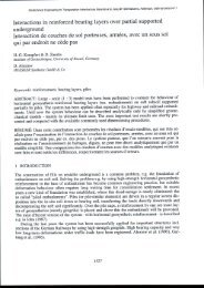
As opposed to conventional column foundations, geotextileencased<br />
columns can be used as a ground improvement method<br />
and as a bearing system <strong>for</strong> very s<strong>of</strong>t soils, because radial<br />
support is guaranteed by the geotextile.<br />
With a non-encased column, the horizontal support <strong>of</strong> the s<strong>of</strong>t<br />
soil must be equal to the horizontal pressure in the column. With<br />
a geotextile-encased column, the horizontal support <strong>of</strong> the s<strong>of</strong>t<br />
soil can be much lower, due to the radial supporting effect <strong>of</strong> the<br />
geotextile casing. The columns act simultaneously as a vertical<br />
drains, but the main effect is the transport <strong>of</strong> the load to a deeper<br />
bearing layer. To carry the high ring tension <strong>for</strong>ces, these<br />
geotextile casing are manufactured seamlessly.<br />
There is horizontal stress in the column σ h,c due to the vertical<br />
stress σ v,c over the column head. There is also horizontal earth<br />
pressure σ h,tot due to the vertical stress σ v,s over the s<strong>of</strong>t soil as<br />
well as the horizontal support <strong>of</strong> the casing.<br />
1.0<br />
2.0<br />
3.0<br />
4.0<br />
5.0<br />
6.0<br />
7.0<br />
8.0<br />
9.0<br />
10.0<br />
11.0<br />
12.0<br />
Ansatz cu 1<br />
cu [kN/m²]<br />
0<br />
1<br />
.0<br />
1,0<br />
2,0<br />
3,0<br />
0<br />
2<br />
.0<br />
5,0<br />
10,0<br />
1) Tiefe = 0 = OK<br />
Staffelung von<br />
der Tiefe bleib<br />
Figure 3 shows the calculation model.<br />
h<br />
σ h,s,tot =<br />
σ h,s + σ h,diff<br />
geotextile<br />
ring tension<br />
<strong>for</strong>ce F r<br />
σ v,s<br />
Figure 3. Calculation Model<br />
σ h,c<br />
σ v,c<br />
2 � r c<br />
2 � r geo<br />
2 � r E<br />
σ h,s,tot =<br />
σ h,s + σ h,diff<br />
sand column<br />
const. volume<br />
(vertical drain)<br />
σ 0<br />
s<strong>of</strong>t soil<br />
This creates a difference in horizontal stress σ h,diff, which results<br />
in ring tensile <strong>for</strong>ces F R in the geotextile casing. The horizontal<br />
support depends also on the vertical pressure over the s<strong>of</strong>t soil<br />
σ v,s, which can be much smaller. As a result we get a stress<br />
concentration above the column head and a lower vertical<br />
pressure over the s<strong>of</strong>t soil and there<strong>for</strong>e a large settlement<br />
reduction.<br />
On the basis <strong>of</strong> the familiar procedure <strong>for</strong> calculation and<br />
dimensioning <strong>of</strong> gravel and sand columns, an analytical<br />
calculation model has been developed which takes the geotextile<br />
casing into account Raithel & Kempfert (1999). More details are<br />
shown in Raithel (1999) and also in Raithel & Kempfert (2000).<br />
The derived equations can be solved by iterative process.<br />
4 DESIGN RESULTS<br />
The sand-filled columns are encased by the seamless, circularwoven<br />
geotextile Ringtrac®, which is made <strong>of</strong> polyester threads.<br />
On the basis <strong>of</strong> the above-described analytical calculation model<br />
and additional FEM-calculations, the grids in table 1 were<br />
designed with more than 60000 columns using different types <strong>of</strong><br />
Ringtrac®.<br />
The stiffness <strong>of</strong> the geotextile casing was between J = 1700<br />
and 2800 kN/m. The maximum high tensile <strong>for</strong>ce <strong>of</strong> the<br />
geotextile varied between 100 and 400 kN/m over the cross<br />
section <strong>of</strong> the dike. The length <strong>of</strong> the columns depended on the<br />
depth <strong>of</strong> the s<strong>of</strong>t soil along the dike line, which varied between 4<br />
and 14 m.<br />
For this project, the ratio <strong>of</strong> the column area A C to the influence<br />
area A E (A C/A E) was between 0.10 and 0.20 = 10% to 20%.<br />
As a result <strong>of</strong> the stability calculations, a geocomposite with<br />
a high tensile strength (maximum high tensile <strong>for</strong>ce 500-1000<br />
kN/m) in the dike base, perpendicular to the dike centerline is<br />
needed, to accelerate the construction <strong>of</strong> the dike and to obtain a<br />
high degree <strong>of</strong> stability in the initial stage <strong>of</strong> construction. It was<br />
also necessary to increase the stability if the area behind the dike<br />
was to be raised to a height <strong>of</strong> 5 to 8 m above sea level. The<br />
AC<br />
AE
factor ß (ß = settlement without GEC / settlement with GEC) <strong>of</strong><br />
ground improvement in s<strong>of</strong>t soil amounts to about ß = 2.5 to 4.<br />
Similar values <strong>for</strong> the ground improvement factors ß could also<br />
seen in model tests.<br />
More details are shown in Kempfert et al (1999). The main<br />
calculation results <strong>for</strong> the design <strong>of</strong> the dike foundation are<br />
shown in table 1.<br />
Table 1. Calculation results<br />
Dikesection<br />
II<br />
III<br />
IV<br />
V<br />
VI<br />
VII<br />
Part<br />
High<br />
[mNN]<br />
Grid<br />
AC/AE<br />
[%]<br />
ca.<br />
number<br />
<strong>of</strong><br />
columns<br />
Settlement<br />
[cm]<br />
middle<br />
side<br />
+9,25<br />
+5,50<br />
17<br />
10<br />
04.400<br />
50<br />
47<br />
middle<br />
side<br />
+8,90<br />
+5,50<br />
15<br />
10<br />
05.700<br />
41<br />
39<br />
middle<br />
side<br />
+8,90<br />
+5,50<br />
15<br />
10<br />
08.000<br />
70<br />
65<br />
middle<br />
side<br />
+8,90<br />
+5,50<br />
15<br />
10<br />
17.000<br />
109<br />
106<br />
middle<br />
side<br />
+8,90<br />
+5,50<br />
15<br />
10<br />
12.000<br />
95<br />
88<br />
middle<br />
side<br />
+8,90<br />
+5,50<br />
20<br />
15<br />
09.800<br />
169<br />
146<br />
5 GEOTEXTILE-ENCASED COLUMN INSTALLATION<br />
Normally, there are two installation methods in practice. With<br />
the excavation method, an open steel pipe is driven to the natural<br />
foundation and its contents are removed by soil auger.<br />
The vibro displacement method, which is more economical, is<br />
commonly used. A steel pipe with two base flaps (which close<br />
upon contact with the soil) is vibrated down to the bearing layer,<br />
displacing the s<strong>of</strong>t soil. The geotextile casing Ringtrac® is<br />
installed and filled with sand. At this stage, the sand in the<br />
column is loose. After drawing up the pipe under vibration a<br />
geotextile-encased column filled with sand <strong>of</strong> medium density is<br />
produced.<br />
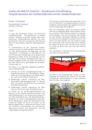
Figure 4. Installation by vibro displacement from <strong>of</strong>fshore pontoon<br />
With both economy and ecology in mind, the vibro displacement<br />
was used <strong>for</strong> the entire Hamburg project. However, the s<strong>of</strong>t soil<br />
surface along the planned dike line varied between 0.8 above sea<br />
level to 2.5 m below sea level. There<strong>for</strong>e, different construction<br />
methods were necessary to install the GEC foundation <strong>for</strong> the<br />
dike.<br />
The majority <strong>of</strong> the columns were installed using equipment<br />
operating from <strong>of</strong>fshore pontoons (110 × 11 m) to better tolerate<br />
the tidal fluctuation (3.5 m water level difference), as shown in<br />
figure 4. At low tide, work continued with the pontoons resting<br />
directly on the s<strong>of</strong>t soil. After installation, the column heads<br />
were stabilized by filling sand between the columns. Notably, no<br />
tidal erosion was observed.<br />
Figure 5 shows a finished column following vibro withdrawal<br />
<strong>of</strong> the steel pipe (open base flaps).<br />
Figure 5. Installed column after drawing the steel pipe under vibration<br />
A further GEC construction method was used <strong>for</strong> numerous road<br />
and railway projects in Germany, the Netherlands and Sweden.<br />
The vibro displacement machine rested on top <strong>of</strong> the installed<br />
columns, with mats under the 120-ton unit to facilitate load<br />
distribution. This land construction method is shown in Figure 6.<br />
Figure 6. The well-tested vibro displacement method on land.<br />
The displacement <strong>of</strong> the s<strong>of</strong>t soil leads to an uplifting <strong>of</strong> the s<strong>of</strong>t<br />
soil within and around the columns grid. The heaving produced<br />
wavelike de<strong>for</strong>mations at the surface <strong>of</strong> the grid. The lifting was<br />
measured at up to 3-8 % <strong>of</strong> the column depth. This effects<br />
duplicated those produced in scale model tests Geduhn & et al.<br />
(2001) conducted be<strong>for</strong>e the start <strong>of</strong> this project. The<br />
measurement results <strong>of</strong> the scale model tests were directly<br />
transferable to those made at the actual site.<br />
Liquefaction <strong>of</strong> the s<strong>of</strong>t soil by compaction energy was not<br />
observed. Measurements showed an increase in the undrained<br />
shear strength <strong>of</strong> the s<strong>of</strong>t soil surrounding the columns.<br />
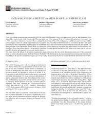
Figure 7 shows one result <strong>of</strong> the measurements <strong>of</strong> the depth<br />
<strong>of</strong> the s<strong>of</strong>t soil be<strong>for</strong>e and immediately after installation <strong>of</strong> the<br />
columns. Further, an increase by a factor <strong>of</strong> 2 in the shear<br />
strength <strong>of</strong> the surrounding s<strong>of</strong>t soil was measured, which shows<br />
the additional stabilizing effect <strong>of</strong> the installation method.
Figure 7. Increase <strong>of</strong> the undrained shear strenght in the s<strong>of</strong>t soil between<br />
the columns in comparison be<strong>for</strong>e and after installation the columns<br />
6 MEASUREMENTS<br />
Due to the different soil conditions along the dike length 7<br />
measurement cross sections are necessary.<br />
In a typical measurement cross section 4 groups with one<br />
earth pressure gauge and one water pressure gauge above the<br />
s<strong>of</strong>t soil layer, as well as two piezometers in the s<strong>of</strong>t soil are<br />
placed. In each cross section a horizontal and two vertical<br />
inclinometers <strong>for</strong> the examination <strong>of</strong> the de<strong>for</strong>mation behaviour<br />
are used.<br />
High+ m NN<br />
max. settlement [m]<br />
8.00<br />
6.00<br />
4.00<br />
2.00<br />
0.00<br />
0.20<br />
0.40<br />
0.60<br />
0.80<br />
1.00<br />
1.20<br />
s<strong>of</strong>t soil depth in m<br />
0<br />
1<br />
2<br />
3<br />
4<br />
5<br />
6<br />
7<br />
8<br />
9<br />
10<br />
11<br />
prognosis<br />
in situ<br />
0 28 56 84 112 140 168 196 224 252<br />
days<br />
Figure 8: Measured settlements in section VI<br />
after installation the columns<br />
be<strong>for</strong>e installation the columns<br />
12<br />
0 10 20 30<br />
cU in kN/m2<br />
40 50 60<br />
measurement<br />
prognosis<br />
On the basis <strong>of</strong> the measurements it can be shown, that the real<br />
soil conditions are better than the soil parameters in the tender<br />
documents, especially with regard to the consolidation<br />
behaviour.<br />
Due to high effectiveness <strong>of</strong> the foundation system, the dike<br />
could be constructed in approx. 9 months to about 7 m height.<br />
There<strong>for</strong>e after 39 weeks, the necessary safety corresponding to<br />
high water could be reached. In figure 6 the measured values <strong>of</strong><br />
the settlements in dike section VI are shown.<br />
7 SUMMARY<br />
The plant site <strong>of</strong> the airplane dockyard (EADS) in Hamburg-<br />
Finkenwerder will be enlarged by approx. 140 ha <strong>for</strong> new<br />
branches <strong>of</strong> production, in particular <strong>for</strong> the production <strong>of</strong> the<br />
new Airbus A 380. The necessary area enlargement is located in<br />
the ‘Mühlenberger Loch’ adjacent to the west <strong>of</strong> the existing<br />
factory site. The area enlargement is carried out by enclosing the<br />
polder with a 2,4 km long dike.<br />
The necessary dike foundations were realized by about<br />
60.000 geotextile encased sand columns (System Möbius GEC)<br />
with a diameter <strong>of</strong> 80 cm, which were sunk to the bearing layers<br />
at depth between 4 and 14 m below the base <strong>of</strong> the dike footing.<br />
Due to the foundation system ‘<strong>Geotextil</strong>e <strong>Encased</strong> Sand<br />
<strong>Columns</strong>’ (GEC) the dike could be constructed on the subsoil<br />
with very small shear strength and high de<strong>for</strong>mability in a<br />
construction time <strong>of</strong> approx. 9 months.<br />
The foundation system ‘<strong>Geotextil</strong>e-<strong>Encased</strong> <strong>Columns</strong>’ (GEC)<br />
was successfully used to found a dike in very s<strong>of</strong>t soil <strong>for</strong> the<br />
purpose <strong>of</strong> land reclamation. Figure 9 shows the dike.<br />
Figure 9: Dike and polder<br />
REFERENCES<br />
Raithel, M. & Kempfert, H.-G. 1999. Bemessung von geokunstst<strong>of</strong>fummantelten<br />
Sandsäulen. Bautechnik 76. Heft 11: 983-991.<br />
Raithel, M. 1999. Zum Trag- und Ver<strong>for</strong>mungsverhalten von<br />
geokunstst<strong>of</strong>fummantelten Sandsäulen. Schriftenreihe Geotechnik.<br />
<strong>Universität</strong> Gh <strong>Kassel</strong>. Heft 6. <strong>Kassel</strong>.<br />
Raithel, M. & Kempfert, H.-G. 2000. Calculation Models <strong>for</strong> Dam<br />
<strong>Foundation</strong>s with <strong>Geotextil</strong>e Coated Sand <strong>Columns</strong>. Proc.<br />
International Conference on Geotechnical & Geological Engineering<br />
GeoEng 2000. Melbourne.<br />
Kempfert, H.-G. et al. 1999. Model Tests <strong>for</strong> Analysis <strong>of</strong> the Bearing and<br />
De<strong>for</strong>mation Behaviour <strong>of</strong> Column <strong>Foundation</strong>s. Geotechnical<br />
Engineering <strong>for</strong> Transportation Infrastructure. Balkema, Rotterdam.<br />
Geduhn, M et al. 2001. Practical Aspects <strong>of</strong> the Design <strong>of</strong> Deep<br />
<strong>Geotextil</strong>e Coated Sand <strong>Columns</strong> <strong>for</strong> the <strong>Foundation</strong> <strong>of</strong> a Dike on<br />
Very S<strong>of</strong>t Soils. Landmarks in Earth Rein<strong>for</strong>cement. Proc.<br />
International Symposium. Kyushu, Japan. Swets & Zeitlinger.