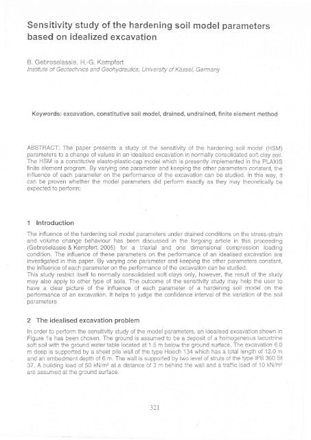
Sensitivity study of the hardening soil model parameters
Sensitivity study of the hardening soil model parameters
Sensitivity study of the hardening soil model parameters

You also want an ePaper? Increase the reach of your titles
YUMPU automatically turns print PDFs into web optimized ePapers that Google loves.
<strong>Sensitivity</strong> <strong>study</strong> <strong>of</strong> <strong>the</strong> <strong>hardening</strong> <strong>soil</strong> <strong>model</strong> <strong>parameters</strong><br />
based on idealized excavation<br />
B. Gebreselassie, H.-G. Kempfert<br />
lnstitute <strong>of</strong> Geotechnics and Geohydraulics, UniversihJ <strong>of</strong> Kassel, Germany<br />
Keywords: excavation, constitutive <strong>soil</strong> <strong>model</strong>, drained, undrained, finite element method<br />
ABSTRACT: The paper presents a <strong>study</strong> <strong>of</strong> <strong>the</strong> sensitivity <strong>of</strong> <strong>the</strong> <strong>hardening</strong> <strong>soil</strong> <strong>model</strong> (HSM)<br />
<strong>parameters</strong> to a change <strong>of</strong> values in an idealised excavation in normally consolidated s<strong>of</strong>t clay <strong>soil</strong>.<br />
The HSM is a constitutive elasto-plastic-cap <strong>model</strong> which is presently impiemented in <strong>the</strong> PLAXIS<br />
finite element program. By varying one parameier and keeping <strong>the</strong> o<strong>the</strong>r <strong>parameters</strong> constant, <strong>the</strong><br />
influence <strong>of</strong> each parameter on <strong>the</strong> performance <strong>of</strong> <strong>the</strong> excavation can be studied. ln this way, ii<br />
can be proven whe<strong>the</strong>r <strong>the</strong> <strong>model</strong> <strong>parameters</strong> did pedorm exactly as <strong>the</strong>y may <strong>the</strong>oretically be<br />
expected to pedorrn<br />
1 lntroduciion<br />
The influence <strong>of</strong> <strong>the</strong> <strong>hardening</strong> <strong>soil</strong> <strong>model</strong> <strong>parameters</strong> under drained conditions on <strong>the</strong> stress-strain<br />
and volume change behaviour has been discussed in <strong>the</strong> forgoing arlicle in this proceeding<br />
(Gebreselassie & Kempferl, 2005) for a triaxial and one dimensionai compression loading<br />
condition. The influence <strong>of</strong> <strong>the</strong>se <strong>parameters</strong> on <strong>the</strong> per-formance <strong>of</strong> an idealised excavation are<br />
investigated in this paper. By varying one parameter and keeping <strong>the</strong> o<strong>the</strong>r <strong>parameters</strong> constant,<br />
<strong>the</strong> influence <strong>of</strong> each parameter on <strong>the</strong> pedormance <strong>of</strong> <strong>the</strong> excavation can be studied.<br />
This <strong>study</strong> restrict itself to normaliy consolidated s<strong>of</strong>t clays only, however, <strong>the</strong> result <strong>of</strong> <strong>the</strong> <strong>study</strong><br />
may also apply to o<strong>the</strong>r type <strong>of</strong> <strong>soil</strong>s. The outcome <strong>of</strong> <strong>the</strong> sensitivity <strong>study</strong> may help <strong>the</strong> user to<br />
have a clear picture <strong>of</strong> <strong>the</strong> influence <strong>of</strong> each parameter <strong>of</strong> a <strong>hardening</strong> <strong>soil</strong> <strong>model</strong> on <strong>the</strong><br />
pedormance <strong>of</strong> an excavation. lt helps to judge <strong>the</strong> confidence interval <strong>of</strong> <strong>the</strong> variation <strong>of</strong> <strong>the</strong> <strong>soil</strong><br />
<strong>parameters</strong><br />
2 The idealised excavation problem<br />
ln order to perform <strong>the</strong> sensitivity <strong>study</strong> <strong>of</strong> <strong>the</strong> <strong>model</strong> parameiers, an ideaiised excavation shown in<br />
Figure 1a has been chosen. The ground is assumed to be a deposit <strong>of</strong> a homogeneous lacustrine<br />
s<strong>of</strong>t <strong>soil</strong> with <strong>the</strong> ground water table located at 1.5 m below <strong>the</strong> ground surface. The excavation 6.0<br />
m deep is supporled by a sheet pile wall <strong>of</strong> <strong>the</strong> type Hoech 134 which has a total length <strong>of</strong> 12.0 m<br />
and an embedment depth <strong>of</strong> 6 m. The wall is supp<strong>of</strong>ied by two level <strong>of</strong> struts <strong>of</strong> <strong>the</strong> type IPB 360 St<br />
37. A buiiding load o{ 50 kN/m2 ai a distance <strong>of</strong> 3 m behind <strong>the</strong> wall and a traific load <strong>of</strong> 10 kN/m2<br />
are assumed at <strong>the</strong> ground sudace.<br />
327
.l<br />
a)L,<br />
t l
Tsat<br />
Table 2. Reference <strong>soil</strong> <strong>parameters</strong> for ihe iniedace elements according to <strong>the</strong> MCM<br />
a=1 a<br />
IkN/m3]<br />
LJ [kN/m,] lkNim2l<br />
lq 5 a^a<br />
AA etAe<br />
tr<br />
tr tncreamenl<br />
J tei<br />
[kNim2] [kNim2]<br />
4 The finite element <strong>model</strong> and <strong>the</strong> ealculation stages<br />
U. ret<br />
ikNim2l<br />
An imporlant parl <strong>of</strong> <strong>the</strong> finite element <strong>model</strong> is shown in Figure 1b, The <strong>model</strong> is extended to a<br />
depth oI 42m where afixed boundary is imposed. At a distance <strong>of</strong> 36 m behind<strong>the</strong> wall and at<strong>the</strong><br />
symmetry axis, a zero horizontal displacement is imposed. The size <strong>of</strong> <strong>the</strong> <strong>model</strong> as a whole is 48<br />
m wide and 42 m high. Triangular elements with '15 nodes are used in generating <strong>the</strong> mesh. This<br />
element provides a fourlh order interpolation for displacements and it involves twelve numerical<br />
integration stress points (Gauss points).The <strong>model</strong> consists <strong>of</strong> 2009 elements, 16499 nodes and<br />
24108 stress points.<br />
For <strong>the</strong> drained analysis <strong>of</strong> <strong>the</strong> idealised excavation problem, <strong>the</strong> HSM <strong>parameters</strong> in Table 1 are<br />
adopted as a reference parameiers for <strong>the</strong> <strong>soil</strong> body. ln order to <strong>study</strong> <strong>the</strong> sensitivity <strong>of</strong> <strong>the</strong> <strong>soil</strong><br />
<strong>parameters</strong>, <strong>the</strong>ir values are varied above and below <strong>the</strong> reference values. The contact between<br />
<strong>the</strong> wall and <strong>the</strong> <strong>soil</strong> body is simulated by mean <strong>of</strong> interJace elements whose material properties are<br />
given in Table 2.<br />
The following construction stages has been followed in <strong>the</strong> computation:<br />
generation <strong>of</strong> <strong>the</strong> initial stresses (K6 - method)<br />
application <strong>of</strong> <strong>the</strong> surcharge and traffic loads<br />
installation <strong>of</strong> <strong>the</strong> wall<br />
first excavation<br />
installation <strong>of</strong> <strong>the</strong> 1st strut and 2nd excavation<br />
installation <strong>of</strong> <strong>the</strong> 2nd strut and 3rd excavation<br />
5 Analysis <strong>of</strong> ihe computation results<br />
5.1 The effect <strong>of</strong> <strong>the</strong> variation <strong>of</strong> <strong>the</strong> Poisson's ralio vur<br />
As it can be seen from Figure 2, <strong>the</strong> parameter yur seems to be a pure deformation parameter. ln o<strong>the</strong>r<br />
words, vur may affect <strong>the</strong> deformation <strong>of</strong> <strong>the</strong> wall and <strong>soil</strong> movements but not <strong>the</strong> eafth pressure and<br />
bending moment <strong>of</strong> <strong>the</strong> wall. A change in v* trom its reference value <strong>of</strong> 0.2 to a smaller<br />
E<br />
-c<br />
o<br />
0r I<br />
-1<br />
LöL<br />
_f<br />
Ä'cL<br />
"f<br />
-6 t-<br />
_l<br />
:/f<br />
-8r<br />
-o!<br />
"f<br />
- lLi -I<br />
-11 --<br />
,^|<br />
- tl -<br />
Stage 0:<br />
Stage 1:<br />
Stage 2:<br />
Stage 3:<br />
Stage 4:<br />
Stage 5;<br />
--€- Reference<br />
---*- v,. = o.so<br />
ä 130i<br />
() I<br />
7C -50 -30 -10 10-150 -50 50 -225 -150 -75 0 75 0 3 6 I 12<br />
horizontal wall earlh pressure Bending moment distance from ihe<br />
deformation [mm] [kN/m1 [kN-m/m] symmetry axis<br />
towards <strong>the</strong> wall [m]<br />
10<br />
0<br />
-1C<br />
tr<br />
F 'cn<br />
:<br />
6 -so<br />
Figure 2. The effect <strong>of</strong> <strong>the</strong> variation <strong>of</strong> y,. on a) deformation <strong>of</strong> <strong>the</strong> wall, b) earlh pressure, c)<br />
bending moment <strong>of</strong> <strong>the</strong> wail, d) heave <strong>of</strong> <strong>the</strong> bottom <strong>of</strong> excavation, and e) settlement at <strong>the</strong> sudace<br />
323<br />
x<br />
0.)<br />
* 120<br />
o<br />
E<br />
I 110<br />
o<br />
e 100<br />
E<br />
c)<br />
= -AA<br />
c)<br />
CD<br />
-50<br />
-b( l<br />
v<br />
I-l<br />
i2 18 24 3A 36 42 4l<br />
disiance behind<br />
<strong>the</strong> wall [m]
value <strong>of</strong> 0.05 and a larger t'alue <strong>of</strong> 0.3 has resulted in a uniform change <strong>of</strong> <strong>the</strong> wall deflection by<br />
about -7 and 4% respectively. Simiiarly, a change <strong>of</strong> <strong>the</strong> heave by about i5 and -i}"k, and a<br />
change <strong>of</strong> <strong>the</strong> suijace settlement by about -21 and 15% respectively are calculared.<br />
5.2 The effect <strong>of</strong> <strong>the</strong> variation <strong>of</strong> <strong>the</strong> coefficient <strong>of</strong> <strong>the</strong> eafth pressure at resi ,ri"<br />
The HSM treats Ki' and K6separately. Whereas Ki" is a <strong>model</strong> parameter which is ciosely reiated<br />
to <strong>the</strong> stiffness <strong>parameters</strong> Esl, Er,, Eoea a,od v*, Ko is purely used to define <strong>the</strong> initial state <strong>of</strong> <strong>the</strong><br />
stresses. For normally consolidated s<strong>of</strong>t <strong>soil</strong>s, however, <strong>the</strong>se values are more or iess <strong>the</strong> same.<br />
The value <strong>of</strong> Ki" as a <strong>model</strong> parameter can not be varied indefinitely. For example, for <strong>the</strong> given<br />
reference <strong>parameters</strong>, <strong>the</strong> minimum and maximum possible values <strong>of</strong> Ki" are 0.437 and 0.71<br />
respectively. Here Ko is assumed to vary with Ki". As it can be seen from Figure 3, <strong>the</strong> parameter<br />
Kj" would affect <strong>the</strong> deformation <strong>of</strong> <strong>the</strong> wall, <strong>the</strong> <strong>soil</strong> movements, <strong>the</strong> eafth pressure and bending<br />
moment <strong>of</strong> <strong>the</strong> wall, although <strong>the</strong> magnitude <strong>of</strong> its influence is moderate as compare to <strong>the</strong> triaxial<br />
case <strong>of</strong> loading (Gebreselassie & Kempferl, 2005). Varying <strong>the</strong> value <strong>of</strong> Ki" from <strong>the</strong> reference<br />
value <strong>of</strong> 0.573 to those extreme values has resulted in a change <strong>of</strong> <strong>the</strong> maximum wall deformation<br />
<strong>of</strong> about -21 and 3% respectively. Similarly, a change <strong>of</strong> <strong>the</strong> heave by about 2 and -9"/", a change<br />
<strong>of</strong> <strong>the</strong> sudace settlement by about -5 and 7"Ä, a change <strong>of</strong> <strong>the</strong> earth pressure by about -21 and<br />
B"k, and a change <strong>of</strong> <strong>the</strong> bending moment by about -18 and 2% respectively are calculated. From<br />
<strong>the</strong> above percentage difference presentation and <strong>the</strong> Figure 3, it appears that varying lhe Ki"<br />
value towards <strong>the</strong> lowest limit is more sensitive than varying its value towards <strong>the</strong> upper iimit,<br />
although <strong>the</strong> difference between <strong>the</strong> reference vaiue and <strong>the</strong> extreme values is almost <strong>the</strong> same.<br />
E<br />
t oc)<br />
D<br />
tt/t I I<br />
fr+l tlD): r' i\<br />
M', II I l' I<br />
64tr<br />
// 1ll'<br />
l,<br />
'/i<br />
i I ,<br />
/rtt! -<br />
b: i I I i:, , tI<br />
:L<br />
l+ Reference l :I i<br />
l--e-K=0.4371 iiI<br />
-i irl<br />
l---a-- Iö-_T<br />
E<br />
b :I<br />
i iI<br />
,:.i iri<br />
t:l<br />
Ko O -t- ---:-;--ffffi<br />
-rT .i i2\i I , \-/. &1<br />
: tlt<br />
= 0.71 I t<br />
r+'J9<br />
r 1 | i .&<br />
Tt la<br />
i+l' .#<br />
lrl i &<br />
trld)<br />
rrltT<br />
,t il9:<br />
i -f- 1 I i&l I I f\<br />
-T<br />
^l , &1 t<br />
'l : ///',1<br />
cL . ö4 I I<br />
; i // /i<br />
.f : 'dd , T<br />
-al // /<br />
-5i - I 6 /'(---+:-<br />
// v I<br />
I A ö l-_ä_<br />
-b - b, 4>'<br />
I ll i ;l-----azlfl<br />
f L-<br />
I f t' , { 8it tr : -r<br />
^t 4:Qi : i "i fl t , l -i<br />
toi<br />
I S{ &O: .,-i : it<br />
1]i \\ ij<br />
12 [t] . I<br />
:<br />
i i ir i<br />
t €j'- ji+<br />
-70 -50 -30 i0 -10 10-150 -50<br />
;<br />
50<br />
horizontal :al wall eafth1<br />
press U re<br />
deforrnation fmm<br />
lkN/ml<br />
Bending moment<br />
[kN-m/m]<br />
r l5U<br />
- E<br />
7 tqo<br />
O<br />
cg<br />
> rcn<br />
(n 'uu<br />
O x<br />
0 3 6 9 12 121821 30364248<br />
disiance from ihe disiance behind<br />
symmetry axis <strong>the</strong> wall [m]<br />
iowards <strong>the</strong> wall [m]<br />
Figure 3. The effect <strong>of</strong> <strong>the</strong> variation <strong>of</strong> Ki" on a) deformaiion <strong>of</strong> <strong>the</strong> wail, b) eafth pressure, c)<br />
bending moment <strong>of</strong> <strong>the</strong> wall, d) heave <strong>of</strong> <strong>the</strong> bottom <strong>of</strong> excavation, and e) settlement at <strong>the</strong> surface<br />
5.3 The effect <strong>of</strong> ihe variation <strong>of</strong> <strong>the</strong> failure factor R;<br />
'.4<br />
rt<br />
;<br />
i<br />
I<br />
ln triaxial and oedometer loading condiiions, ii has been proved thai <strong>the</strong> failure factor Rl plays an<br />
imporlant role in enhancing or retarding <strong>the</strong> failure <strong>of</strong> <strong>the</strong> <strong>soil</strong> body (Gebreselassie & Kempferl,<br />
2005). lts influence on ihe iciealised excavation, however. seems to be minimum, wiih excepiion <strong>of</strong><br />
<strong>the</strong> settlement behind ihe wall (Figure a)). Varying <strong>the</strong> value <strong>of</strong> ,Qrfi'om ihe reference vaiue <strong>of</strong> 0.83<br />
c)<br />
*t o<br />
i<br />
-9 1<br />
o<br />
-o c)1<br />
20<br />
10<br />
c0<br />
o9C<br />
(d<br />
c)<br />
E Fon<br />
10<br />
0<br />
-tu<br />
-o -30<br />
E AJ<br />
E -40<br />
o<br />
(f)<br />
-60<br />
-74
tc 0.67 and 0.97 has resulted in a change <strong>of</strong> <strong>the</strong> surface settlement by about -8 and 69," respectively.<br />
For all <strong>the</strong> o<strong>the</strong>r cases, <strong>the</strong> difference remains below +5%.<br />
tr<br />
.C<br />
c)<br />
o<br />
-r - (a)l<br />
i',i<br />
a' t- |<br />
:::<br />
^i:l i:j<br />
-ql) i<br />
:t<br />
-si<br />
ii--e- Reference<br />
:D-_n07<br />
v ilI- v,J,<br />
---*- Rr = 0.67<br />
-50 -30 -10 10-150 -50 50 -225 -150 -75 0 75<br />
Bending moment<br />
horizontal wall<br />
deformation [mm]<br />
eadh pressure<br />
IkNim]<br />
IkN-m/m1<br />
E<br />
E<br />
c<br />
.o<br />
(g<br />
O<br />
X q)<br />
E o<br />
o<br />
_o<br />
G)<br />
5<br />
(6<br />
c)<br />
o<br />
-a<br />
l5u<br />
14A<br />
'130<br />
120<br />
110<br />
100<br />
036912<br />
distance from <strong>the</strong><br />
symmetry axis<br />
towards <strong>the</strong> wall [m]<br />
- IU<br />
F<br />
tr ar.<br />
c^-<br />
O -JU<br />
E<br />
o<br />
= _tA<br />
0)<br />
a<br />
-an<br />
-60<br />
-74<br />
12 18 24 30 36 42 48<br />
distance behind<br />
<strong>the</strong> wall [m]<br />
Figure 4. The effect <strong>of</strong> <strong>the</strong> variation <strong>of</strong> Eron a) deformation <strong>of</strong> <strong>the</strong> wall, b) earth pressure, c)<br />
bending moment <strong>of</strong> <strong>the</strong> wall, d) heave <strong>of</strong> <strong>the</strong> bottom <strong>of</strong> excavation, and e) settlement at <strong>the</strong> surface<br />
5.4 The effect <strong>of</strong> <strong>the</strong> variation <strong>of</strong> <strong>the</strong> consirained modulus Eo"6<br />
As shown in Figure 5, a variation <strong>of</strong> <strong>the</strong> constrained modulus Eo,a by about +50% its reference<br />
value, has resulted in a change <strong>of</strong> <strong>the</strong> maximum wall deflection by about -30 and 5% respectively.<br />
Similarly, a change <strong>of</strong> <strong>the</strong> heave by about -'17 and -4"/", a change <strong>of</strong> <strong>the</strong> sudace settlement by<br />
about -24 and 2"/", a change <strong>of</strong> <strong>the</strong> maximum eafth pressure above <strong>the</strong> bottom <strong>of</strong> excavation by<br />
about -17 and 2o/", and a change <strong>of</strong> <strong>the</strong> bending moment by about -23 and 3% respectively has<br />
been observed (Figures 5). Hence, <strong>the</strong> following conclusion may be drawn with regard to <strong>the</strong><br />
response <strong>of</strong> <strong>the</strong> excavation to <strong>the</strong> change <strong>of</strong> Eoea.<br />
a) ln all cases Eoea is more sensible to a change <strong>of</strong> value below <strong>the</strong> reference value than to<br />
value greater than <strong>the</strong> reference. lt can be seen from Figure 6 that a reduction <strong>of</strong> <strong>the</strong><br />
reference .;alue <strong>of</strong> Eoea by 50% has caused a reduction <strong>of</strong> <strong>the</strong> wall and <strong>soil</strong> movements,<br />
<strong>the</strong> active earth pressure and <strong>the</strong> bending moment by about 17 1o 307o, whereas<br />
increasing <strong>the</strong> reference value by same amount (50%) show no significant influence (2 to<br />
5%), lt seems that <strong>the</strong> ratio <strong>of</strong> EsdEo"a is more imp<strong>of</strong>tant than <strong>the</strong> absolute value <strong>of</strong> <strong>the</strong><br />
Eo"6.For <strong>the</strong> reference case, this ratio becomes 1.1. lf lhe Eo"a is increased or decreased<br />
by about 50%, <strong>the</strong> ratio becomes 0.73 and 2.20 respectively. The ratio in <strong>the</strong> case <strong>of</strong><br />
increasing Eo"a is more closer to <strong>the</strong> reference ratio than <strong>the</strong> o<strong>the</strong>r way round. This might<br />
be <strong>the</strong> reason why <strong>the</strong> change oI Eoea is more sensible to a value below ihe reference than<br />
above <strong>the</strong> reference value.<br />
b) Contrary to expectation, a reduced value <strong>of</strong> Eo"6 has resulted in a reduction <strong>of</strong> wall and <strong>soil</strong><br />
movements.<br />
c) Figure 6b shows a reduced active pressure and an increased passive pressure for <strong>the</strong><br />
case <strong>of</strong> Eoea smaller than <strong>the</strong> reference value. This again contradicts with <strong>the</strong> reduced wall<br />
movement that is discussed in (b). A reduced wall movement would have resulted a higher<br />
active pressure and lower passive pressure.<br />
d) A reduced active pressure on one side and an increased passive pressure on <strong>the</strong> o<strong>the</strong>r<br />
side has resulted in a reduced bending moment, which seems logical in respect to <strong>the</strong><br />
given loading condition but not in a general sense.<br />
325
-a'- | -L ,<br />
^l:<br />
-4<br />
-o<br />
_1<br />
-8<br />
,9<br />
10<br />
11<br />
--€- Reference<br />
^ n
than iha'i fi'om <strong>the</strong> reference rvalue. This is mainly due io <strong>the</strong> upward displacement <strong>of</strong> ihe wall. The<br />
whole <strong>soil</strong> body seems to heave upwards due to lower values <strong>of</strong> Eu,<br />
5.6 The effect <strong>of</strong> <strong>the</strong> variation <strong>of</strong> <strong>the</strong> secant modulus <strong>of</strong> elasticity Eso<br />
Figure 7 shows <strong>the</strong> effect <strong>of</strong> <strong>the</strong> variation <strong>of</strong> Esc by t50% from its reference value. These variations<br />
<strong>of</strong> Eso have resulted in a change <strong>of</strong> <strong>the</strong> maximum wall deflection by about 45 and -24"/"<br />
respectiveiy. Similar change <strong>of</strong> ihe heave by about 21 and 11"h, <strong>the</strong> sudace seirlement by about 71<br />
and -37"/o, <strong>the</strong> maximum earth pressure above <strong>the</strong> botiom <strong>of</strong> excavation by about'.l9 and -15%,<br />
and <strong>the</strong> maximum bending moment by about 27 and 1B% respectively has been observed.<br />
At first glance, it seems that an increased wall movement shouid result in higher passive resistance,<br />
because <strong>the</strong> <strong>soil</strong> is more close to <strong>the</strong> passive limit state. However, as <strong>the</strong> numerical <strong>study</strong> <strong>of</strong><br />
<strong>the</strong> mobilisation <strong>of</strong> <strong>the</strong> passive resistance (Gebreselassie, 2003; Gebreselassie & Kempfed, 2005)<br />
also shows, <strong>the</strong> passive resistance is lower for lower values <strong>of</strong> <strong>the</strong> modulus for a given displacement<br />
<strong>of</strong> <strong>the</strong> wall and keeping <strong>the</strong> shear parameter constant. This is exactly what one can observe<br />
in Figure 7. Lower value <strong>of</strong> Esa leads to higher wall movement but a lower passive resistance and<br />
vice versa.<br />
E<br />
5 oo<br />
-uIi<br />
"7 1:<br />
s[-.<br />
----r---<br />
---A-<br />
-lt<br />
l_<br />
II<br />
T<br />
I<br />
i<br />
T<br />
i<br />
horizontal wall<br />
deformation [mm]<br />
-iso -50 50 -2sa -150 -50 50<br />
earth pressure Bending moment<br />
[kN/m] [kN-m/m]<br />
E<br />
E<br />
c<br />
=(ü<br />
cd<br />
o<br />
xq)<br />
o<br />
E<br />
o<br />
o<br />
-o c)<br />
-c.<br />
cd<br />
0)<br />
cd<br />
o)<br />
-C<br />
'l 50<br />
1<br />
'1<br />
1<br />
1<br />
1<br />
40<br />
30<br />
20<br />
10<br />
036912<br />
distance {rom <strong>the</strong><br />
symmetry axis<br />
towards <strong>the</strong> wall [m]<br />
'10<br />
0<br />
10<br />
c-tr<br />
i-30<br />
F -+o<br />
E<br />
O.^<br />
F c)<br />
u) -60<br />
-70<br />
-80<br />
-90 1<br />
2182430364248<br />
distance behind<br />
<strong>the</strong> wall [m]<br />
Figure 7, The effect <strong>of</strong> <strong>the</strong> variation <strong>of</strong> Eso on a) deformation <strong>of</strong> <strong>the</strong> wall, b) eadh pressure, c)<br />
bending moment <strong>of</strong> <strong>the</strong> wall, d) heave <strong>of</strong> <strong>the</strong> bottom <strong>of</strong> excavation, and e) settlement at <strong>the</strong> sudace<br />
6 Sunrmary<br />
A sensitivity <strong>study</strong> <strong>of</strong> <strong>the</strong> <strong>soil</strong> <strong>parameters</strong> for HSM has been conducted based on an idealised excavation<br />
in normally consolidated cohesive <strong>soil</strong>s in order to <strong>study</strong> ihe influence <strong>of</strong> <strong>the</strong>se <strong>parameters</strong><br />
on <strong>the</strong> pedormance <strong>of</strong> an excavation. The result <strong>of</strong> <strong>the</strong> <strong>study</strong> may be summarised as follows:<br />
E56 Seerns to lead <strong>the</strong> role <strong>of</strong> influencing <strong>the</strong> wall displacement, <strong>the</strong> earth pressure, <strong>the</strong><br />
bending moment and <strong>the</strong> settlement behind <strong>the</strong> wall. Due to <strong>the</strong> non-linearity, however,<br />
increasing its value does not necessarily produce <strong>the</strong> same effect as <strong>the</strong> o<strong>the</strong>r way round .<br />
Its influence on bottom heave is limited only to <strong>the</strong> heave near <strong>the</strong> wall and its influence<br />
ceases towards <strong>the</strong> middle <strong>of</strong> <strong>the</strong> excavation. E ,' plays a dominant role on <strong>the</strong> heave <strong>of</strong><br />
<strong>the</strong> excavation and <strong>the</strong> displacement <strong>of</strong> <strong>the</strong> wall toe, but it has insignificant inf{uence on<br />
<strong>the</strong> bending moment. vu, has oniy an etfect on <strong>the</strong> botiom heave and settlement at <strong>the</strong><br />
sudace. Fr shows a negligible etfect on all <strong>the</strong> cases.<br />
Ki" value may affect <strong>the</strong> deformations, bending moment and <strong>the</strong> eafth pressure. although<br />
aa1 )/ /
<strong>the</strong> magnitude <strong>of</strong> its influence is moderate as compare to <strong>the</strong> triaxial state <strong>of</strong> stress. Kf"<br />
value towards <strong>the</strong> lowest limit is more sensitive than varying its value towards <strong>the</strong> upper<br />
Iimit, although <strong>the</strong> diiference between <strong>the</strong> reference value and <strong>the</strong> extreme values is<br />
almost <strong>the</strong> same.<br />
. The sensitivity <strong>study</strong> <strong>of</strong> <strong>the</strong> Eoea shows that <strong>the</strong> ralio EsdEo"a is more imp<strong>of</strong>tant than <strong>the</strong><br />
absolute value <strong>of</strong> Eo"a.<br />
7 List <strong>of</strong> Symbols and Abbreviations<br />
Elit = .""unt modulus ai 50% <strong>of</strong> <strong>the</strong> failure & = ratio <strong>of</strong> <strong>the</strong> stress at failure and <strong>the</strong><br />
stress and at effeciive reference pressure <strong>of</strong> p'ef ultimate stress<br />
Ef,'o=constrainedmodulus at p'4 K;" =coefficient<strong>of</strong> <strong>the</strong>earthpressureat<br />
Eff' = unlreloading modulus ^t p'{ rest for normally consolidated <strong>soil</strong>s<br />
E = modulus <strong>of</strong> elasticity v u, = Poisson's ratio for un/reloading<br />
7",, = saturated unit weight <strong>of</strong> <strong>soil</strong> v = Poisson's ratio<br />
E = effective angle <strong>of</strong> intemal friction m = exponent in <strong>the</strong> power law<br />
ö = wallfriction HSM = Hardening Soil Model<br />
c' = effective cohesion MCM = Mohr-Coulomb Model<br />
I References<br />
Brinkgreve R.B.J. 2002. Hand book <strong>of</strong> <strong>the</strong> finite element code for <strong>soil</strong> and rock analysis "PLAXIS". Balkema Publisher,<br />
Rotterdam.<br />
Gebreselassie B. 2003. Experimental, analytical and numerical investigations <strong>of</strong> excavations in normally consolidated s<strong>of</strong>t <strong>soil</strong>s.<br />
Dissertation, University <strong>of</strong> Kassel,.Schriftenreihe Geotechnik, Heft 1 4.<br />
Gebreselassie B., Kempfert H.-G. 2005. Mobilisation <strong>of</strong> <strong>the</strong> eärth resistance <strong>of</strong> a normally consolidated cohesive <strong>soil</strong>s. The Proceedings<br />
<strong>of</strong> <strong>the</strong> 16tn lnternational conference on Soil Mechanics and Geotechnical Engineering, Osaka, Japan (in press).<br />
Gebreselassie 8., Kempfert H.-G. 2005. Calibration <strong>of</strong> <strong>soil</strong> <strong>parameters</strong> for an elasto-plastic cap <strong>model</strong> under drained condiiion.<br />
The Proceedings <strong>of</strong> <strong>the</strong> 1 1s lnternational conference <strong>of</strong> IACMAG, Turin, ltaty (in this volume).<br />
328
Proceedings <strong>of</strong> <strong>the</strong> Eleventh lnternational Conference<br />
on Computer Methods and Advances in Geomechanics<br />
TORINO / ITALY I 19.24 JUNE 2OO5<br />
Prediction, analysis and design ln<br />
geomechanical applications<br />
Edited by:<br />
Giovanni Barla and Marco Barla<br />
Department <strong>of</strong> Structural and Geotechnical Engineering,<br />
Politecnico di Torino, ltaly<br />
VOLUME 1<br />
PATRON EDITORE<br />
BOLOGNA 2OO5