GeoVision USB Dongle Specifications.
GeoVision USB Dongle Specifications.
GeoVision USB Dongle Specifications.
You also want an ePaper? Increase the reach of your titles
YUMPU automatically turns print PDFs into web optimized ePapers that Google loves.
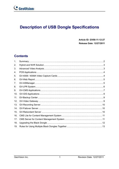
Description of <strong>USB</strong> <strong>Dongle</strong> <strong>Specifications</strong><br />
Contents<br />
Article ID: GV00-11-12-27<br />
Release Date: 12/27/2011<br />
1. Summary..........................................................................................................................2<br />
2. Hybrid and NVR Solution .................................................................................................3<br />
3. Advanced Video Analysis.................................................................................................3<br />
4. POS Applications .............................................................................................................4<br />
5. GV-4008 / 4008A Video Capture Cards ...........................................................................4<br />
6. GV-Web Report................................................................................................................5<br />
7. GV-ASManager................................................................................................................5<br />
8. GV-LPR System...............................................................................................................6<br />
9. GV-CMS Applications.......................................................................................................7<br />
10. GV-GIS Applications ........................................................................................................9<br />
11. GV-Backup Center ...........................................................................................................9<br />
12. GV-Video Gateway ..........................................................................................................9<br />
13. GV-Recording Server.....................................................................................................10<br />
14. GV-Failover Server ........................................................................................................10<br />
15. GV-Redundant Server ...................................................................................................10<br />
16. CMS Lite for Content Management System .................................................................. 11<br />
17. CMS Server for Content Management System ............................................................. 11<br />
18. Upgrading the Black <strong>Dongle</strong> ..........................................................................................12<br />
19. Rules for Using Multiple Black <strong>Dongle</strong>s Together..........................................................13<br />
<strong>GeoVision</strong> Inc. 1 Revision Date: 12/27/2011
1. Summary<br />
Certain features of GV software are protected by a <strong>USB</strong> dongle. It is required to insert an<br />
appropriate <strong>USB</strong> dongle to the system for the protected features to work.<br />
There are three kinds of colors in <strong>USB</strong> dongles: Blue, Yellow and Black. Some software can<br />
only use one kind of dongle, and some can use more than one to perform different functions.<br />
The below table illustrates the three color dongles and their associated product types.<br />
Only Black <strong>Dongle</strong> requires the drivers to work and can be upgraded to include more<br />
functions. It is also the only dongle that you can use more than one in a single system. See 18.<br />
Upgrading the Black <strong>Dongle</strong> and 19. Rules for Using Multiple Black <strong>Dongle</strong>s Together later in<br />
this document.<br />
Click on Product Type of interest to link to the related topic in this document.<br />
<strong>Dongle</strong> Picture Product Type<br />
Blue <strong>Dongle</strong><br />
• POS Applications<br />
• GV-LPR System<br />
• GV-CMS Applications<br />
Yellow <strong>Dongle</strong><br />
• GV-CMS Applications<br />
Black <strong>Dongle</strong><br />
• Hybrid and NVR Solutions<br />
• Advanced Video Analysis<br />
• POS Applications<br />
• GV-4008 / 4008A Cards<br />
• GV-Web Report<br />
• GV-ASManager<br />
• GV-LPR System<br />
• GV-CMS Applications<br />
• GV-GIS Applications<br />
• GV-Backup Center<br />
• GV-Video Gateway<br />
• GV-Failover Server<br />
• GV-Redundant Server<br />
• CMS Lite for Content Management System<br />
• CMS Server for Content Management System<br />
Note: GV-Recording Server comes in internal dongles only.<br />
<strong>GeoVision</strong> Inc. 2 Revision Date: 12/27/2011
2. Hybrid and NVR Solutions<br />
<strong>GeoVision</strong> provides two solutions for IP video surveillance:<br />
• Hybrid Solution: Integrates analog videos with digital videos from IP video devices.<br />
• NVR Solution: A software-based system GV-NVR without requiring a video capture card.<br />
Both Hybrid and NVR Solutions come with 32 free IP channels when connecting to <strong>GeoVision</strong><br />
IP video devices. To connect to third-party IP devices, you need a NVR <strong>Dongle</strong>.<br />
• The dongle options include: 1, 2, 4, 6, 8, 10, 12, 14, 16, 18, 20, 22, 24, 26, 28, 30, 32<br />
IP channel(s).<br />
• The dongle comes in two types, internal and external dongles.<br />
3. Advanced Video Analysis<br />
1. A “Black” AVP (Advanced Video Process) dongle is required for these functions to work:<br />
• Panorama View<br />
• Defog function<br />
• Video Stabilizer<br />
• Crowd Detection<br />
• Advanced Unattended Object<br />
• Advanced Scene Change Detection<br />
• Advanced Missing Object<br />
• Digital Object Tracking<br />
• Face Count<br />
2. The dongle comes in two types, internal and external dongles.<br />
3. It is required to install drivers from the software CD for the AVP dongle to work.<br />
4. If you already have a NVR dongle, you can upgrade the dongle to include the AVP<br />
functions. For details, see 18. Upgrading the Black <strong>Dongle</strong>.<br />
<strong>GeoVision</strong> Inc. 3 Revision Date: 12/27/2011
4. POS Applications<br />
1. Graphic-Mode POS Device: An appropriate <strong>USB</strong> dongle of “Blue” color is required for<br />
GV-System connecting with a graphic-mode POS device to receive transaction data.<br />
• The dongle comes in external dongles.<br />
2. Window-Based Direct POS Integration: An appropriate <strong>USB</strong> dongle of “Black” color is<br />
required for GV-System to perform the direct POS integration without requiring a GV-Data<br />
Capture Box.<br />
• The direct POS integration is available only on GV-System version 8.3 or later.<br />
• It is required to install drivers from the software CD for the <strong>USB</strong> dongle to work.<br />
• The dongle comes in two types, internal and external dongles.<br />
• The following dongle options are available:<br />
GV-System V8.4 or later GV-<strong>USB</strong> <strong>Dongle</strong> with 1, 2, 4, 8, 12, or 16 port(s)<br />
GV-System earlier than V8.4 GV-<strong>USB</strong> <strong>Dongle</strong> with 16 ports<br />
For serial port connection, up to 4 POS devices can be connected to one GV-System. For<br />
TCP/IP connection, up to 16 POS devices can be connected to one GV-System.<br />
5. GV-4008 / 4008A Video Capture Cards<br />
1. An appropriate <strong>USB</strong> dongle of “Black” color is required for GV-4008 / GV-4008A Cards to<br />
work.<br />
2. The dongle comes in two types, internal and external dongles.<br />
3. It is required to install drivers from the software CD for the <strong>USB</strong> dongle to work.<br />
<strong>GeoVision</strong> Inc. 4 Revision Date: 12/27/2011
6. GV-Web Report<br />
1. An appropriate <strong>USB</strong> dongle of “Black” color is required for the PC running the GV-Web<br />
Report program.<br />
2. The dongle options include: 200, 500 and 1000 units of GV-Systems and GV-Smart<br />
Boxes.<br />
3. The dongle comes in external type.<br />
4. It is required to install drivers from the software CD for the <strong>USB</strong> dongle to work.<br />
Note that if multiple GV-<strong>USB</strong> <strong>Dongle</strong>s are inserted, the dongle that supports greater number<br />
of clients will be used.<br />
7. GV-ASManager<br />
1. An appropriate <strong>USB</strong> dongle of “Black” color is required for the PC running the<br />
GV-ASManager program.<br />
2. The dongle options include: 4, 10, 30, 50, 255 units of GV-AS Controllers.<br />
3. The dongle comes in external type.<br />
4. It is required to install drivers from the software CD for the <strong>USB</strong> dongle to work.<br />
Note that if multiple GV-<strong>USB</strong> <strong>Dongle</strong>s are inserted, the dongle that supports greater number<br />
of clients will be used.<br />
<strong>GeoVision</strong> Inc. 5 Revision Date: 12/27/2011
8. GV-LPR System<br />
1. With a video capture card on GV-LPR System: An appropriate <strong>USB</strong> dongle of “Blue” or<br />
“Black” color is required for GV-LPR System to work.<br />
• The dongle options include: 1, 2, 4, 6, 8 lane(s).<br />
• The dongle comes in external type.<br />
2. Combination of GV-LPR System and GV-System: An appropriate <strong>USB</strong> dongle of “Blue”<br />
or “Black” color is required for the PC running GV-LPR System and GV-System together.<br />
• The dongle options include: 1, 2, 4, 6, 8 lane(s).<br />
• The dongle comes in external type.<br />
3. Without a video capture card on GV-LPR System: To implement the software-based<br />
GV-LPR System, you need an appropriate <strong>USB</strong> dongle of “Black” color to activate the<br />
video stream from GV-DSP LPR.<br />
• The <strong>USB</strong> dongle allows the video stream of 8 channels in maximum.<br />
• The dongle comes in external type.<br />
• It is required to install drivers from the software CD for the <strong>USB</strong> dongle to work.<br />
Note that if multiple GV-<strong>USB</strong> <strong>Dongle</strong>s are inserted, the dongle that supports greater number<br />
of clients will be used.<br />
<strong>GeoVision</strong> Inc. 6 Revision Date: 12/27/2011
9. GV-CMS Applications<br />
1. GV-CMS applications include four independently developed programs: Center V2,<br />
Dispatch Server, Vital Sign Monitor (VSM) and Control Center. An appropriate <strong>USB</strong> dongle<br />
is required for each CMS program to work.<br />
2. The CMS dongle comes in two types, internal and external dongles.<br />
3. There are three types of <strong>USB</strong> dongles used in CMS applications: Blue <strong>Dongle</strong>, Yellow<br />
<strong>Dongle</strong> and Black <strong>Dongle</strong>. Table 1 illustrates the supported CMS software of each<br />
dongle.<br />
• Blue <strong>Dongle</strong>: One computer can only be attached with one type of Blue <strong>Dongle</strong>. You<br />
cannot use more than one Blue <strong>Dongle</strong> together.<br />
• Black <strong>Dongle</strong>:<br />
a. One computer can be attached with more than one Black <strong>Dongle</strong>.<br />
b. Only Black <strong>Dongle</strong> can be upgraded to include more functions. For details, see<br />
18. Upgrading the Black <strong>Dongle</strong>.<br />
c. It is required to install drivers from the software CD for the <strong>USB</strong> dongle to work.<br />
• A combination of Blue <strong>Dongle</strong>, Yellow <strong>Dongle</strong> and Black <strong>Dongle</strong> used on the same<br />
computer is possible. But remember the rule that Control Center and Center V2<br />
cannot be run together, and Center V2 and Dispatch Server cannot be run together.<br />
Blue <strong>Dongle</strong><br />
Table 1: <strong>Dongle</strong> types for CMS Applications<br />
1. Control Center (IP Matrix)<br />
2.Center V2 Pro<br />
3.Center V2 Pro + VSM<br />
4. Dispatch Server<br />
5. Dispatch Server + VSM<br />
6. VSM<br />
Yellow <strong>Dongle</strong> Control Center (IP Matrix)<br />
Black <strong>Dongle</strong><br />
1. Control Center (IP Matrix)<br />
2. Control Center (IP Matrix) + Advanced Video Analysis<br />
3. Control Center (IP Matrix) + VSM<br />
4. Control Center (IP Matrix) + VSM + Advanced Video Analysis<br />
5. Center V2 Pro<br />
6. Center V2 Pro + VSM<br />
7. Dispatch Server<br />
<strong>GeoVision</strong> Inc. 7 Revision Date: 12/27/2011
8. Dispatch Server + VSM<br />
9. VSM<br />
10. VSM + Control Center (IP Matrix)<br />
11. VSM + Center V2 Pro<br />
12. VSM + Dispatch Server<br />
4. Table 2 illustrates the required dongle type for each CMS software version. Note (*) the<br />
IP Matrix function is only available on version 8.2 or later.<br />
Center V2 Pro<br />
Dispatch<br />
VSM<br />
Control Center<br />
(IP Matrix *)<br />
Table 2: <strong>USB</strong> dongle requirement for CMS software version<br />
<strong>Dongle</strong> Type<br />
V6.0 / 6.05<br />
Software Version<br />
V6.1 / 6.11 / 7.0 / 7.05 V8.0 V8.1 / 8.11 / 8.12 V8.2 or later<br />
Blue <strong>Dongle</strong> Yes<br />
Black <strong>Dongle</strong> No Yes<br />
Blue <strong>Dongle</strong> Yes<br />
Black <strong>Dongle</strong> No Yes<br />
Blue <strong>Dongle</strong><br />
Black <strong>Dongle</strong><br />
N/A<br />
Yes<br />
No Yes<br />
Blue <strong>Dongle</strong> Yes Yes Yes<br />
Yellow <strong>Dongle</strong> N/A<br />
No Yes Yes<br />
Black <strong>Dongle</strong><br />
No No Yes<br />
<strong>GeoVision</strong> Inc. 8 Revision Date: 12/27/2011
10. GV-GIS Applications<br />
1. An appropriate <strong>USB</strong> dongle of “Black” color is required for the GV-GIS to work.<br />
2. The primary <strong>USB</strong> dongle provides 1, 3, 5, 10 vehicle connections. The number limit is 500<br />
connections with the increment of 5 connections at a time.<br />
Inform your sales representative the required number of vehicle connections so the<br />
dongle can be delivered upon your requirements. Otherwise, you can upgrade your<br />
primary dongle later by following the instructions in the section of 18. Upgrading the Black<br />
<strong>Dongle</strong>.<br />
Example: If you need 33 vehicle connections and already have a primary dongle, you<br />
need to upgrade the primary dongle from 10 to 35 connections.<br />
3. The dongle comes in two types, internal and external dongles.<br />
4. It is required to install drivers from the software CD for the <strong>USB</strong> dongle to work.<br />
11. GV-Backup Center<br />
1. An appropriate <strong>USB</strong> dongle of “Black” color is required for the GV-Backup Center to<br />
work.<br />
2. The GV-<strong>USB</strong> <strong>Dongle</strong> supports connection with 200 GV-IP Devices.<br />
3. The dongle comes in two types, internal and external dongles.<br />
4. It is required to install drivers from the software CD for the <strong>USB</strong> dongle to work.<br />
12. GV-Video Gateway<br />
1. An appropriate <strong>USB</strong> dongle of “Black” color is required for the GV-Video Gateway to<br />
work.<br />
2. The GV-<strong>USB</strong> <strong>Dongle</strong> supports connection with 128 IP channels of both GV-IP video<br />
devices and third-party IP devices.<br />
3. The dongle comes in two types, internal and external dongles.<br />
4. It is required to install drivers from the software CD for the <strong>USB</strong> dongle to work.<br />
<strong>GeoVision</strong> Inc. 9 Revision Date: 12/27/2011
13. GV-Recording Server<br />
1. An appropriate <strong>USB</strong> dongle of “Black” color is required for the GV-Recording Server to<br />
work.<br />
2. The dongle options include:<br />
• GV-IP video devices only: 32, 36, 40, 44, 48, 52, 56, 60, 64, 68, 72, 76, 80, 84, 88,<br />
92, 96, 100, 104, 108, 112, 116, 120, 124, 128 IP channels.<br />
• Third-party IP devices (Includes GV-IP video devices): 32, 36, 40, 44, 48, 52, 56,<br />
60, 64, 68, 72, 76, 80, 84, 88, 92, 96, 100, 104, 108, 112, 116, 120, 124, 128 IP<br />
channels.<br />
3. The dongle comes in internal type.<br />
4. It is required to install drivers from the software CD for the <strong>USB</strong> dongle to work.<br />
14. GV-Failover Server<br />
1. An appropriate <strong>USB</strong> dongle of “Black” color is required for the GV-Failover Server to<br />
work.<br />
2. The GV-<strong>USB</strong> <strong>Dongle</strong> supports connection with 128 <strong>GeoVision</strong> and third-party IP<br />
channels.<br />
3. The dongle comes in two types, internal and external dongles.<br />
4. It is required to install drivers from the software CD for the <strong>USB</strong> dongle to work.<br />
15. GV-Redundant Server<br />
1. An appropriate <strong>USB</strong> dongle of “Black” color is required for the GV-Redundant Server to<br />
work.<br />
2. The GV-<strong>USB</strong> <strong>Dongle</strong> supports connection with 128 <strong>GeoVision</strong> and third-party IP<br />
channels.<br />
3. The dongle comes in two types, internal and external dongles.<br />
4. It is required to install drivers from the software CD for the <strong>USB</strong> dongle to work.<br />
<strong>GeoVision</strong> Inc. 10 Revision Date: 12/27/2011
16. CMS Lite for Content Management System<br />
1. The CMS Lite supports 50 units of <strong>GeoVision</strong> digital signage devices for free. To connect<br />
more than 50 devices to the CMS Lite, an appropriate <strong>USB</strong> dongle of “Black” color is<br />
required.<br />
2. Different number of connections is available in increments of 10 connections and up to<br />
500 connections maximum.<br />
3. The dongle comes in external dongles.<br />
4. It is required to install drivers from the software CD for the <strong>USB</strong> dongle to work.<br />
17. CMS Server for Content Management System<br />
1. An appropriate <strong>USB</strong> dongle of “Black” color is required for the CMS Server to work.<br />
2. Different number of connections is available in increments of 5 connections and up to<br />
1000 connections maximum.<br />
3. The dongle comes in external dongles.<br />
4. It is required to install drivers from the software CD for the <strong>USB</strong> dongle to work.<br />
<strong>GeoVision</strong> Inc. 11 Revision Date: 12/27/2011
18. Upgrading the Black <strong>Dongle</strong><br />
Black <strong>Dongle</strong>s can be upgraded to include more functions or enhance the system. You need<br />
to collect the data from your dongle and send it back to <strong>GeoVision</strong> for an upgrade. To upgrade<br />
your dongle, follow these steps:<br />
1. Each dongle has its own serial number. Find it on the side of the dongle. Later this serial<br />
number will be used in naming the files for upgrading.<br />
2. Insert the dongle to the computer.<br />
3. In the GV folder, double-click GVUsbKeyUpClient.exe. This dialog box appears.<br />
4. To retrieve the data from the dongle, click Select All. The information of the dongle is<br />
displayed in the information field. Note the displayed number of “HW Serial” should be<br />
the same as that on the dongle.<br />
5. To save the data to your local computer, click Save Key ID Data. If you have more than<br />
one dongle to upgrade, click Batch Save. Different dongle data will be saved as<br />
separate files. The file will be named after the serial number on the dongle and saved as<br />
*.out. For example, if a dongle serial number is 7116442, the file is named<br />
“NVR-7116442.out”.<br />
<strong>GeoVision</strong> Inc. 12 Revision Date: 12/27/2011
6. Send this data file to <strong>GeoVision</strong> at sales@geovision.com.tw. The <strong>GeoVision</strong> will examine<br />
the data file and send an *.in file back to you. The file name also includes the serial<br />
number of that dongle. In this example, the data file you will receive is named<br />
“NVR-7116442.in”.<br />
7. After you receive the updated file, insert the correct dongle matching the .in file you<br />
receive, and then run GVUsbKeyUpClient.exe.<br />
8. Click Select All to read the dongle, click Upgrade and then open the updated file to<br />
upgrade the dongle. You can also select more than one dongle in the list and click Batch<br />
Upgrade to upgrade them at the same time. Make sure these dongles match the<br />
updated files you receive.<br />
19. Rules for Using Multiple Black <strong>Dongle</strong>s Together<br />
Other than upgrading a Black <strong>Dongle</strong> to expand functionality and capability of your system,<br />
you can also use different Black <strong>Dongle</strong>s together to achieve the purpose.<br />
When multiple <strong>USB</strong> dongles are used, the number of channels supported on each dongle is<br />
combined except the following products: GV-ASManager, GV-Web Report and GV-LPR<br />
System.<br />
In the following example, NVR (number) indicates the number of third-party IP channels<br />
supported by NVR <strong>Dongle</strong> and AVP means the AVP (Advanced Video Process) function. The<br />
combination of the four dongles gives the GV-System capability of AVP and 24 channels of<br />
third-party IP devices in addition to the 32 free channels of GV-IP Devices but limited to 32<br />
channels in total.<br />
<strong>Dongle</strong> 1 <strong>Dongle</strong> 2 <strong>Dongle</strong> 3 <strong>Dongle</strong> 4<br />
AVP NVR 4 NVR 4 + AVP NVR 16 + AVP<br />
Combined Result:<br />
AVP + NVR 24 (third-party IP devices) + 32 free channels of GV-IP Devices < 32 channels<br />
<strong>GeoVision</strong> Inc. 13 Revision Date: 12/27/2011


