GV-NVR GV - Security Camera Systems
GV-NVR GV - Security Camera Systems
GV-NVR GV - Security Camera Systems

You also want an ePaper? Increase the reach of your titles
YUMPU automatically turns print PDFs into web optimized ePapers that Google loves.
© 2011 GeoVision, Inc. All rights reserved.<br />
All GeoVision Products are manufactured in Taiwan.<br />
Quick Start Guide<br />
http://www.geovision.com.tw<br />
GV-<strong>NVR</strong><br />
V8.5<br />
2011/07<br />
English<br />
<strong>NVR</strong>V85-A<br />
1<br />
Introduction<br />
Welcome to the GV-<strong>NVR</strong> Quick Start Guide. In the following sections, you<br />
will learn the basic requirements and configurations of using GV-<strong>NVR</strong>.<br />
For the detailed instructions of use, see the DVR User’s Manual on the<br />
GV-<strong>NVR</strong> Software DVD.<br />
Note: GV-<strong>NVR</strong> automatically comes with 32 free IP channels when<br />
connected with GeoVision IP video devices. To connect with third-party<br />
IP devices, you need to purchase a <strong>NVR</strong> Dongle and install it to the<br />
computer. To have hardware watchdog function on your GV-<strong>NVR</strong><br />
system, you can purchase an Internal-type <strong>NVR</strong> Dongle.<br />
Packing List<br />
• GV-<strong>NVR</strong> Software DVD x 1<br />
• GV-<strong>NVR</strong> Quick Start Guide x 1<br />
• Protection Key (<strong>NVR</strong> Dongle) available upon order x 1
Types of Dongle Options<br />
Two types of USB dongles are available to connect with third-party IP<br />
devices: External-type <strong>NVR</strong> Dongle and Internal-type <strong>NVR</strong> Dongle.<br />
The dongle options include 1, 2, 4, 6, 8, 10, 12, 14, 16, 18, 20, 22, 24, 26,<br />
28, 30 and 32 IP channel(s).<br />
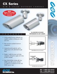
External-type <strong>NVR</strong> Dongle<br />
Internal-type <strong>NVR</strong> Dongle<br />
Internal-type <strong>NVR</strong> Dongle is not only used for connecting with third-party<br />
IP video devices, but also built with Hardware Watchdog function which<br />
restarts the computer when Windows crashes. The dongle is inserted to<br />
the USB header on the motherboard.<br />
For details on supported third-party IP camera models, please visit<br />
GeoVision’s website: http://www.geovision.com.tw/english/4_21.asp<br />
2<br />
System Requirements<br />
The GV-<strong>NVR</strong> system can support up to 32 channels. The following table<br />
lists the minimum and recommended system requirements needed to run<br />
the GV-<strong>NVR</strong>.<br />
OS<br />
CPU<br />
Memory<br />
VGA<br />
32-bit<br />
64-bit<br />
IMPORTANT:<br />
Up to 4<br />
Channels<br />
Up to 8<br />
Channels<br />
Up to 16<br />
Channels<br />
Windows XP / Windows Vista / Windows 7 /<br />
Windows Server 2008<br />
Windows 7 / Windows Server 2008<br />
Core 2 Duo,<br />
2.4 GHz<br />
Core 2 Quad, 2.4 GHz<br />
2 × 1 GB Dual Channels / 2 x 2 GB Dual Channels<br />
(see IMPORTANT 2)<br />
ATI X1300<br />
Up to 32<br />
Channels<br />
Core i7,<br />
2.8 GHz<br />
1. For the users of 32-bit Windows, the memory limit of GV-<strong>NVR</strong> is 1.7 GB<br />
with 2 GB RAM. For the users of 64-bit Windows, the memory limit of<br />
GV-<strong>NVR</strong> is 1.7 GB with 2 GB RAM and 3 GB with 4 GB RAM. If the high<br />
memory issue persists, the GV-<strong>NVR</strong> will become unstable.<br />
2. Some GV hardware accessories and GV-System functions are not<br />
available to GV-<strong>NVR</strong> users. Please note the following<br />
unavailable GV-System functions:<br />
• Adjustment of codec and resolution for third-party devices<br />
• Recording quality<br />
• Pre-Recording using RAM<br />
• Hard Disk Calculator<br />
• Noise Detection to reduce file size<br />
• Video Lowpass Filter
3<br />
Options<br />
Optional devices can expand your GV-<strong>NVR</strong>’s capabilities and versatility.<br />
Contact your dealer for more information.<br />
AVP<br />
(Advanced Video<br />
Process) Functions<br />
Internal USB Dongle<br />
GV-Data Capture V3<br />
Box<br />
GV-Hub V2<br />
GV-COM V2<br />
GV-IO Box (4 Ports)<br />
GV-IO Box (8 Ports)<br />
AVP (Advanced Video Process) functions include<br />
Panorama View, Video Stabilizer, Defogging and<br />
etc. You can add the AVP functions to the<br />
GV-<strong>NVR</strong> by using an additional AVP Dongle, or<br />
upgrading your external or internal <strong>NVR</strong> Dongle<br />
to have the AVP functions.<br />
The USB dongle can provide the Hardware<br />
Watchdong function to the GV-<strong>NVR</strong> system by<br />
restarting the computer when Windows crashes.<br />
You need to connect the dongle internally on the<br />
motherboard.<br />
GV-Data Capture V3 Box can integrate the<br />
GV-<strong>NVR</strong> to an electronic POS system, while<br />
GV-Data Capture V3E Box can establish such<br />
integration through LAN or Internet.<br />
An easy way for serial port extension. This hub<br />
can add 4 RS-232 / RS-485 serial ports through<br />
the GV-<strong>NVR</strong>’s USB port.<br />
This unit can add 1 RS-232 / RS-485 serial port<br />
through the GV-<strong>NVR</strong>’s USB port.<br />
GV-IO Box 4 Ports provides 4 inputs and 4 relay<br />
outputs, and supports both DC and AC output<br />
voltages. A USB port is also provided for PC<br />
connection.<br />
GV-IO Box 8 Ports provides 8 inputs and 8 relay<br />
outputs, and supports both DC and AC output<br />
voltages. You can connect the unit to the PC<br />
either by using its USB port or through network<br />
by using its Ethernet module.<br />
GV-IO Box (16 Ports)<br />
GV-NET/IO Card<br />
(I/O Box Mode)<br />
GV-Joystick<br />
GV-Keyboard V3<br />
GV-IO Box 16 Ports provides 16 inputs and 16<br />
relay outputs, and supports both DC and AC<br />
output voltages. You can connect the unit to the<br />
PC either by using its USB port or through<br />
network by using its Ethernet module.<br />
The GV-NET/IO Card is a RS-485 / RS-232<br />
interface converter, providing 4 inputs and 4 relay<br />
outputs. It supports both DC and AC output<br />
voltages.<br />
GV-Joystick facilitates the PTZ camera control. It<br />
can be either plugged into the GV-<strong>NVR</strong> for<br />
independent use or connected to GV-Keyboard to<br />
empower the operation.<br />
GV-Keyboard V3 is used to program and operate<br />
GV-<strong>NVR</strong> and PTZ cameras. Through RS-485<br />
configuration, it can control up to 16 GV-<strong>NVR</strong><br />
systems. In addition, you can connect PTZ<br />
cameras directly to the keyboard for PTZ control.
4<br />
USB Driver Installation<br />
It is required to install the driver of USB dongle before use. After you insert<br />
the USB dongle to the computer where GV-<strong>NVR</strong> is installed, the Found<br />
New Hardware Wizard will automatically detect the device. Ignore the<br />
Wizard and follow these steps to install the driver:<br />
1. Insert the GV-<strong>NVR</strong> Software DVD. It will run automatically and a window<br />
pops up.<br />
Figure 1<br />
2. Select Install or Remove GeoVision GV-Series Driver, and then click<br />
Install GeoVision USB Devices Driver. This dialog box appears.<br />
Figure 2<br />
3. Click Install to install the driver. When the installation is complete, this<br />
message will appear: Install done!<br />
4. To verify that the driver is installed correctly, go to Windows Device<br />
Manager and expand DVR-Devices. You should see the entry of<br />
GV-Series USB Protector.<br />
Figure 3<br />
Continuned on the reverse >>>
5<br />
System Installation<br />
Before You Start<br />
For optimal performance of your system, it is important to follow these<br />
recommendations before installing the GV-<strong>NVR</strong>:<br />
• It is strongly recommended to use two separate hard disks. One is for<br />
installing Windows OS and GV-<strong>NVR</strong> software, and the other is for<br />
storing recorded files and system logs.<br />
• When formatting the two hard disks, select NTFS as the file system.<br />
• GV-<strong>NVR</strong> is a multi-channel video recording system. With normal use of<br />
the system, the drive containing video files will become fragmented.<br />
This is because GV-<strong>NVR</strong> constantly stores video files of multi channels<br />
simultaneously, and video files will be scattered all over the drive. It is<br />
not necessary to regularly perform disk defragmentation. Since<br />
GV-<strong>NVR</strong> software and video files are stored on two separated hard<br />
disks, the performance of GV-<strong>NVR</strong> will not be affected.<br />
• Since the size of transmitted data from IP cameras may be quite large<br />
and reach beyond the transfer rate of a hard disk, you should note the<br />
total of recording frame rates that you can assign to a single hard disk,<br />
as listed below:<br />
Frame rate limit in a single hard disk<br />
Video resolution<br />
2560x1920 (5M)<br />
2560x1600 (4M)<br />
2048x1536 (3M)<br />
1600x1200 (2M)<br />
1280x960 (1.3M) 200 fps<br />
640x480 (VGA)<br />
320x240 (CIF)<br />
MJPEG<br />
Frame Rate Bit Rate<br />
30 fps<br />
60 fps<br />
60 fps<br />
120 fps<br />
480 fps<br />
480 fps<br />
102.26 Mbit/s 240 fps<br />
73.49 Mbit/s<br />
64.73 Mbit/s<br />
41.16 Mbit/s<br />
30.04 Mbit/s<br />
11.42 Mbit/s<br />
5.16 Mbit/s<br />
H.264<br />
Frame Rate Bit Rate<br />
240 fps<br />
480 fps<br />
480 fps<br />
480 fps<br />
640 fps<br />
640 fps<br />
21.24 Mbit/s<br />
15.28 Mbit/s<br />
10.52 Mbit/s<br />
9.16 Mbit/s<br />
5.77 Mbit/s<br />
2.54 Mbit/s<br />
0.75 Mbit/s<br />
MPEG<br />
Frame Rate Bit Rate<br />
480 fps<br />
640 fps<br />
640 fps<br />
Note: The above data was determined using the bit rate listed above<br />
and hard disks with average R/W speed above 80MB/s.<br />
The frame rate limit is based on the resolution of video sources. The<br />
higher video resolutions, the lower frame rates you can assign to a<br />
single hard disk. In other words, the higher frame rates you wish to<br />
record, the more hard disks you need to install. For the information of<br />
recording frame rates, you may consult the user’s manual of the IP<br />
camera that you wish to connect to.<br />
• Before installing the GV-<strong>NVR</strong>, make sure DirectX 9.0c is already<br />
installed on your computer.<br />
6.30 Mbit/s<br />
3.27 Mbit/s<br />
1.03 Mbit/s
Installing the GV-<strong>NVR</strong><br />
To install the GV-<strong>NVR</strong>, follow these steps:<br />
1. Insert the GV-<strong>NVR</strong> System Software DVD. The Install Program<br />
window pops up automatically (see Figure 1).<br />
2. Click Install GeoVision xxx System (ex. Install GeoVision V8.5.0.0<br />
System).<br />
3. To install the Main System, select GeoVision Main System, and<br />
follow the on-screen instructions.<br />
4. Follow the above steps to install other programs one by one.<br />
Uninstalling the GV-<strong>NVR</strong><br />
To uninstall the GV-<strong>NVR</strong>, follow these steps:<br />
1. Close any open programs because your computer will restart during<br />
the uninstalling process.<br />
2. Click the Start button, click Control Panel, and then click Add or<br />
Remove Programs.<br />
3. In the Currently installed programs list, select GeoVision GV-<strong>NVR</strong><br />
System, and then click Remove.<br />
Figure 4<br />
4. When you are prompted to confirm the program removal, click Yes.<br />
Note: Uninstalling the GV-<strong>NVR</strong> will not delete video files and log files<br />
previously saved in the computer.<br />
6<br />
Adding IP Video Sources<br />
The procedures for adding an IP camera, Video Server and Compact DVR<br />
may vary. The following is the setup procedure for an IP camera in the<br />
system.<br />
1. On the main screen, click the Configure button, select System<br />
Configure and click IP <strong>Camera</strong> Install. This dialog box appears.<br />
Figure 5<br />
• To add an IP camera from a list of the IP cameras on the LAN, click<br />
Scan <strong>Camera</strong>.<br />
• To manually set up an IP camera, follow steps 2 to 7.<br />
2. Click Add <strong>Camera</strong>. This dialog box appears.<br />
Figure 6
3. Type the IP address, username and password of the IP camera. Keep<br />
or modify the default HTTP port 80. Select a camera brand and device<br />
from the drop-down list. This dialog box appears.<br />
Figure 7<br />
4. The options in the setup dialog box may vary depending on the camera<br />
brand.<br />
• Port: Video streaming port number.<br />
• Stream Type: You may have the option of single streaming only or<br />
both single and dual streaming.<br />
• Codec type: You may have the option of MPEG4, JPEG, or H.264.<br />
If the selected camera supports dual streaming, the preview codec<br />
and recording codec can be set differently.<br />
• Resolution: Select resolutions for preview and recording.<br />
6. Click Apply. The IP camera is added to the list.<br />
7. Click the listed camera, and select Display position to map the IP<br />
camera to a channel on the GV-System.<br />
Figure 8<br />
8. The Status column now should display “Connected”. Click OK.<br />
For more details, see Hybrid and <strong>NVR</strong> Solution, Chapter 2, DVR User’s<br />
Manual on the GV-<strong>NVR</strong> Software DVD.
7<br />
Upgrading GV-<strong>NVR</strong><br />
The Black Dongle can be upgraded to include more functions or enhance<br />
the system. You need to collect the data from your dongle and send it back<br />
to GeoVision for an upgrade. The upgrade is charged services. To<br />
upgrade your dongle, follow these steps:<br />
1. Each dongle has its own serial number. Find it on the side of the<br />
dongle. Later this serial number will be used in naming the files for<br />
upgrading.<br />
SIC+7116442<br />
SIC+7116442<br />
Figure 9<br />
2. Insert the dongle to the computer.<br />
3. In the GV folder, double-click GVUsbKeyUpClient.exe. This dialog<br />
box appears.<br />
Figure 10<br />
4. To retrieve the data from the dongle, click Select All. The information of<br />
the dongle will be displayed in the information field. Note the displayed<br />
number of “HW Serial” should be the same as that on the dongle.<br />
5. To save the data to your local computer, click Save Key ID Data. If you<br />
have more than one dongle to upgrade, click Batch Save. Different<br />
dongle data will be saved as separate files. The file will be named after<br />
the serial number on the dongle and saved as *.out. For example, if a<br />
dongle serial number is 7116442, the file is named “<strong>NVR</strong>-7116442.out”.<br />
6. Send this data file to GeoVision at sales@geovision.com.tw. The<br />
GeoVision will examine the data file and send an *.in file back to you.<br />
The file name also includes the serial number of that dongle. In this<br />
example, the data file to be sent back is named “<strong>NVR</strong>-7116442.in”.<br />
7. After you receive the updated file, insert the correct dongle matching<br />
the .in file you receive, and then run GVUsbKeyUpClient.exe.<br />
8. Click Select All to read the dongle, click Upgrade and then open the<br />
updated file to upgrade the dongle. You can also select more than one<br />
dongle in the list and click Batch Upgrade to upgrade them at the<br />
same time. Make sure these dongles match the updated files you<br />
receive.<br />
9F, No. 246, Sec. 1, Neihu Rd.,<br />
Neihu District, Taipei, Taiwan<br />
Tel: +886-2-8797-8377<br />
Fax: +886-2-8797-8335<br />
sales@geovision.com.tw<br />
http://www.geovision.com.tw