Novapoint Civil Construction
Novapoint Civil Construction
Novapoint Civil Construction

You also want an ePaper? Increase the reach of your titles
YUMPU automatically turns print PDFs into web optimized ePapers that Google loves.
Editor:<br />
Trine Jentoft Mortensen<br />
tjm@vianova.no<br />
Graphic Design:<br />
Trine Jentoft Mortensen<br />
tjm@vianova.no<br />
PRINTED BY: GD GRUPPEN Danmark<br />
Contents:<br />
Leader s. 3<br />
Geotechnics and <strong>Novapoint</strong> s. 4<br />
Highway 44 s. 6<br />
<strong>Novapoint</strong> use in Denmark s. 11<br />
<strong>Novapoint</strong> goes offshore s. 14<br />
Importing laserscan data files s. 17 7<br />
Rovaniemi city s. 18<br />
Tallinn Techical University<br />
New double track in Norway -<br />
s. 19<br />
“all in 3D” s. 20<br />
<strong>Novapoint</strong> <strong>Civil</strong> <strong>Construction</strong> s. 24<br />
New Airport in Faeroe Islands s. 28<br />
Belgian TucRail s. 31<br />
<strong>Novapoint</strong> in France s. 32<br />
Norway<br />
Vianova Systems AS<br />
www.vianovasystems.no<br />
Denmark<br />
Vianova Systems Denmark AS<br />
www.vianova.dk<br />
Sweden<br />
Vianova Systems Sweden AB<br />
www.vianova.se<br />
Finland<br />
Vianova Systems Finland OY<br />
www.vianova.fi<br />
Latvia<br />
Vianova Systems Latvia SIA<br />
www.vianova.lv<br />
Spain<br />
Vianova Systems Spain SL<br />
www.vianova.es<br />
France<br />
Vianova Systems France SAS<br />
www.vianova-systems.fr<br />
England<br />
Vianova Systems UK LTD<br />
www.vianovasystems.co.uk<br />
Thailand<br />
Vianova Systems AS, Thailand<br />
www.vianova.co.th<br />
Vietnam<br />
Vianova Systems Vietnam Ltd.<br />
www.vianova.com.vn<br />
Benelux<br />
GEOMAP<br />
www.geomapgis.com<br />
Novanews on the Web:<br />
www.novapoint.com<br />
L E A D E R<br />
Merete Tøndel, Vianova Systems, Managing Director<br />
Revolutionary stimulation packages as a result of the financial<br />
crisis demands an overall transportation policy. This is discussed<br />
in The Economist from June 20th 2009. The following interesting<br />
statement could be read: ”An integrated system for planning –<br />
one that includes passenger rail, freight, highways and mass<br />
transport – does not exist. Full analyses of projects’ costs or benefits<br />
are rare”. And finally: ”There may be a new vision for transport,<br />
but it will never progress until someone is willing to pay for<br />
it”… Think about this for a moment …<br />
The article is about the USA, but it might as well have been written<br />
here in the Northern countries and Europe. These are challenges<br />
that must be addressed by the entire business. Our vision<br />
is to finish what has been seen as the greatest challenge in the<br />
transportation sector in the USA, but we need help. We have used<br />
the technology for the Norwegian Public Road Administration, The<br />
Norwegian National Rail Administration and the Norwegian<br />
Mapping Authorities. The Road Administration has first of all put<br />
their faith in us, and is a main contributor for us being where we<br />
are today. In addition private developers have, and Skanska<br />
should be mentioned first of all, shown us that they are willing to<br />
order and pay!<br />
… Northern roads take lives. This alone is an argument for us to<br />
build more and safer roads and it has to be done fast. Good roads<br />
are also an important condition for a hard pressured Northern<br />
industry. This is why the Northern authorities have said clearly<br />
that they will use several extra billions on roads, and that we will<br />
use modern building methods to finish them twice as fast as<br />
today.<br />
This business has been given an especially large responsibility in<br />
the financial crisis! The business is also facing great challenges in<br />
their way of doing things. The seniors in this house are talking<br />
lively about when the transportation business went from drawings<br />
to CAD. Now everybody is talking about the model, and here we<br />
will work together with you as our customer to develop the best<br />
way of working. Our goal is for you to take the step!<br />
From July 1st, we will be sole distributor of <strong>Novapoint</strong> in Norway<br />
and Sweden. We then have the same distribution model in all<br />
countries. The main reason for this choice is that we want to get<br />
closer to you as a customer. We want to be present at the desks<br />
of users and decision-makers, and give you advice on everything<br />
connected to a total delivery of software within infrastructure.<br />
Many of our employees have heavy experience in road construction-<br />
almost 300 years altogether. In addition, we have close to<br />
700 years of total experience in software development for the<br />
infrastructure!<br />
Takes you there!<br />
Merete Tøndel<br />
Take the step!<br />
3
<strong>Novapoint</strong> GeoSuite Toolbox offers a wide range of tools<br />
for geotechnical engineers for the modelling and presentation<br />
of ground investigations.<br />
The program pack is the result of a Norwegian/Swedish<br />
cooperation financed by NFR and via funds provided by<br />
the Norwegian project partners in the GeoSuite project.<br />
The partners represent both the private, public, university<br />
and college environments within geotechnical engineering<br />
in Norway and include NGI,<br />
Multiconsult, The Directorate<br />
of Public Roads, GeoVita,<br />
NTNU and SINTEF and the IT<br />
companies Vianova Systems<br />
AS, Vianova GeoSuite AB<br />
and the AutoGRAF association<br />
in Sweden. The<br />
AutoGRAF association brings<br />
together around 90% of the<br />
geotechnical environment in<br />
Sweden. The project began<br />
with phase 1 which started in<br />
2003 and has moved on from<br />
1 January 2007 to phase 2,<br />
which will be completed in 2009.<br />
4
Jan Ludvigsson, Vianova GeoSuite<br />
Vianova GeoSuite AB is the company in the Vianova<br />
network which has geotechnical engineering as its<br />
competence area. The company is located in<br />
Stockholm and manages and carries out the majority<br />
of the programming work. It is linked to the<br />
ViaNova network through ViaNova Systems AS,<br />
which is co-owner of the company. The AutoGRAF<br />
user association and the GeoSuite project in<br />
Norway are represented on the company’s board,<br />
to ensure high technical understanding and competence.<br />
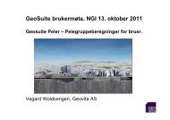
The GeoSuite project has, through bringing together<br />
cooperative partners both in Sweden and<br />
Norway, succeeded in creating new products and in<br />
further developing existing products to become the<br />
complete and powerful program package <strong>Novapoint</strong><br />
GeoSuite Toolbox, which is designed specifically for<br />
the professional geotechnical engineering environment<br />
in Scandinavia. <strong>Novapoint</strong> GeoSuite Toolbox<br />
consists of GS Presentation for data administration<br />
and for the presentation of geotechnical investigations<br />
and the four calculation programs GS Stability<br />
for stability calculations, GS Settlement for settlement<br />
calculations, GS Pile Groups for pile group calculations<br />
and GS Supported Excavations for sheet<br />
pile calculations.<br />
The first version was launched in the summer of<br />
2006 and since then the program package has been<br />
extensively adopted both in Sweden and Norway.<br />
All large players in the market are customers. We<br />
can, in addition to the project partners, mention<br />
customers such as Rambøll, WSP, Sweco VBB and<br />
the Swedish Road Administration. Parts of the program<br />
package have been used in project work and<br />
education at for example NTNU and Chalmers.<br />
More than 300 licences have been sold in Sweden<br />
and Norway. The number of users is however much<br />
more than this figure indicates, as most licences<br />
are network licences.<br />
Courses are offered at several locations in Norway<br />
and Sweden. In Sweden alone more than 770<br />
participants<br />
have taken part in settlement calculation<br />
courses so far in 2007. 7<br />
GEOSUITE TOOLBOx<br />
GS (GeoSuite) Toolbox has a simple program<br />
superstructure which handles general project data,<br />
GS Archive, in which new assignments/projects are<br />
set up. Project handling maintains control of your<br />
project and shows what has been completed in the<br />
project, which documents are included in the project<br />
and starts the tools which are required to carry<br />
out calculations and data administration.<br />
The central product in the program package is GS<br />
Presentation. All geotechnical investigations which<br />
are carried out in a project are saved and administered<br />
here. Data is normally input via raw data files<br />
from field investigations, which is then presented in<br />
AutoCAD/<strong>Novapoint</strong> after being edited. GS<br />
Presentation is integrated with <strong>Novapoint</strong> Roads<br />
and Terrain, which makes it a rational tool for the<br />
geotechnical engineer in day to day operations.<br />
Data is processed, interpreted and transferred to<br />
the road and terrain model in GS Presentation,<br />
which in turn means that geotechnical profiles can<br />
recover data in the form of calculated models of<br />
(for example) rock surfaces in a profile. The rock<br />
profile can be generated with data from the geotechnics,<br />
but also from other data sources such as<br />
maps, surveying data, interpreted orthophotos etc.<br />
GS Presentation replaces the earlier product<br />
GeoPlot as from version 17. 7 This however means<br />
that old data no longer can be used. Old data can<br />
be input into new projects directly from existing<br />
GeoPlot projects.<br />
The calculation program can be used as a free<br />
standing calculation program without the use of<br />
AutoCAD without problem. However, links to<br />
<strong>Novapoint</strong> can be used to obtain valuable information<br />
and help to retrieve geometry in the form of<br />
terrain models and borehole profiles as the basis for<br />
building up soil type model at a calculation point.<br />
INTERESTED IN FINDING OUT MORE?<br />
For more information, visit <strong>Novapoint</strong>’s web site!<br />
Contact person details and product sheets, course<br />
information, user support and other information are<br />
also available here.<br />
Go to:<br />
www.novapoint.no, or<br />
www.novapoint.se<br />
If you want to find out more about geotechnics in<br />
<strong>Novapoint</strong>, please contact:<br />
Kristin Lysebo, Vianova Systems AS,<br />
Sandvika, Norway, tlf (+47) 67 81 70 00<br />
e-mail: kristin.lysebo@vianova.no<br />
or<br />
Jan Ludvigsson, Vianova GeoSuite AB,<br />
Solna, Sweden, tlf (+46) 08-27 69 90<br />
e-mail: jan.ludvigsson@geosuite.se<br />
5
<strong>Novapoint</strong> Virtual Map is developed such that the model can be organised in groups and with the option to turn<br />
these off and on. A road surface can therefore be switched off to view the infrastructure under the ground.<br />
6
Highway 44<br />
Today’s highway 44 through the centre of the town of Klepp in the Jæren district of Norway has a<br />
traffic volume of approximately 12,000 vehicles per day. The Norwegian Public Roads<br />
Administration decided in 2003 to build a by-pass to lead through-traffic around the centre, to<br />
improve traffic safety, the environment and accessibility.<br />
Asbjørn Hagen, ViaNova Plan og Trafikk<br />
TOTAL CONTRACT<br />
The Norwegian Public<br />
Roads Administration<br />
has chosen to implement<br />
the project as a<br />
total contract. This<br />
type of contract type<br />
is becoming increasingly<br />
common within<br />
road construction.<br />
The Norwegian Public<br />
Roads Administration<br />
enters into an agreement<br />
with a contractor<br />
for the planning<br />
and construction of a<br />
road section.<br />
Operation and maintenance<br />
after completion<br />
of the project<br />
is not normally<br />
included in these contracts. OPS contracts, which<br />
we are familiar with from the E39 Trøndelag motorway<br />
and the E18 Sørlandet motorway, can be considered<br />
to be an expanded total contract. These<br />
contracts include financing and operation/maintenance<br />
for 25 years after opening, which are in addition<br />
to the assignments in the total contract.<br />
In a total contract, the project is planned and built<br />
in accordance with the requirements which The<br />
Norwegian Public Roads Administration has specified<br />
in the tender documentation. Adopted development<br />
plans and relevant road standards and municipal<br />
guidelines form an important part of this basis.<br />
The Norwegian Public Roads Administration as<br />
developer makes the final decision on solutions via<br />
approving drawings.<br />
There are several positive aspects associated with<br />
total contracts:<br />
• This type of contract promotes interaction<br />
between planning and execution. Time is to a<br />
much greater extent used on development of<br />
better solution rather than on contractual dis-<br />
cussions. The developer’s main task will primarily<br />
include contract follow up and solution<br />
approval.<br />
• Experience shows that there is a strong focus in<br />
total contracts on project progress.<br />
Implementation times are therefore significantly<br />
reduced when compared with a normal developer<br />
managed contract. In other words, it takes<br />
significantly less time from planning start to<br />
completion where structured as a total contract<br />
as opposed to a normal contract. Total contracts<br />
give completed roads in ‘record time’.<br />
However, there is a risk that too little time is allocated<br />
to the optimalization and selection of solutions.<br />
A positive development would be if The<br />
Norwegian Public Roads Administration managed<br />
project planning in the tender documentation in a<br />
better way than we have so far seen. It should be<br />
stipulated in the contract that there should be a<br />
period at the start of the project that only should be<br />
used for planning work. The milestone should be<br />
approved work documentation. The road construction<br />
work could then begin.<br />
COMPETITIVE TENDERING<br />
The tender period extended from May to August<br />
2006. Competition was very intense. However,<br />
Skanska won the assignment and construction was<br />
started on approximately 1 December in the same<br />
year.<br />
ViaNova has participated in a planning group which<br />
has a contract with Skanska for the planning of the<br />
road project. The planning group, which is led by<br />
Dr. ing. A. Aas-Jakobsen, has participated in the<br />
offer phase and is now preparing working drawings<br />
and survey data as a documentation for construction<br />
site implementation.<br />
The assistance provided to Skanska in the tender<br />
phase included the preparation of offer drawings<br />
and volume calculations. After entering into a contract<br />
and a brief optimalization phase, the detail<br />
7
planning work was started. The first working drawings<br />
were delivered on approximately 1 December<br />
2006, one month after start up. Project completion<br />
is 15 December 2007. 7 I.e. only one year from the<br />
detail planning start to project completion.<br />
ThE PROJECT<br />
The road project<br />
includes approximately<br />
4 km of new<br />
highway 44, approximately<br />
2 km of local<br />
roads and a similar<br />
length of footpaths.<br />
A rock tunnel, three<br />
bridges and four<br />
underpasses are<br />
included in the project.<br />
There is in addition<br />
a significant<br />
amount of municipal<br />
line re-routing.<br />
The rock tunnel has<br />
been stipulated to Normal profile surface section<br />
protect the valuable<br />
recreational area by Kleppelunden. The road would<br />
probably otherwise have been planned as a surface<br />
road on the west side of ridge if this condition had<br />
not been included.<br />
The road section has three crossings which are<br />
designed as roundabouts.<br />
Dimensioning traffic 20 years<br />
after opening is estimated to<br />
be 18,000 AADT. At this traffic<br />
volume level, the road should<br />
be designed as a four lane<br />
road with central reservation.<br />
The tunnel should, in accordance<br />
with standards, have<br />
two shafts with two lanes in<br />
each direction. The Norwegian<br />
Public Roads Administration<br />
has approved an exemption from road and tunnel<br />
standards and set the road standard to a wide two<br />
lane road with central barrier.<br />
Tunnel cross section T10.5 is selected to achieve a<br />
1.5 m separation zone in the centre of the tunnel.<br />
Barriers are not acceptable in a tunnel, as this<br />
would hinder evacuation in the event of an accident.<br />
PLANNING<br />
The project is planned digitally using the different<br />
professional modules in <strong>Novapoint</strong>. Organisation of<br />
8<br />
drawings and folder structure follows The<br />
Norwegian Public Roads Administration’s PROF<br />
standard. A digital terrain model is set up based on<br />
digital maps and supplementary surveying data<br />
along the entire route. The surveying was carried<br />
out by Skanska Survey.<br />
The OPS project E39<br />
Klett - Bårdshaug in<br />
the county of Sør-<br />
Trøndelag and the<br />
tender phase for<br />
OPS E18 Grimstad -<br />
Kristiansand has<br />
allowed ViaNova to<br />
develop a strong<br />
cooperation with<br />
Skanska. This cooperation<br />
continues in<br />
this project.<br />
Cooperation has<br />
contributed to the<br />
development of<br />
both planning<br />
methodology and<br />
software. A modern road construction site with GPS<br />
controlled machines and equipment needs much<br />
more comprehensive surveying data than was previously<br />
the norm. Road models have been supplied<br />
for all roads, both road surfaces and formations.<br />
Surveying data has in addition been prepared in kof<br />
format for all lines, manholes,<br />
lighting foundations, sign foundations,<br />
cable trenches etc.<br />
Surveying data in the form of<br />
goals from a reference line has as<br />
far as possible been avoided.<br />
A work procedure where the<br />
solutions are verified in a 3D<br />
model is required if satisfactory<br />
cross-profession co-ordination<br />
and survey data control is to be<br />
achieved. Controls carried out in<br />
the ‘old fashioned’ way in 2D using associated<br />
height calculations can no longer be accepted, as<br />
the solution also must be cross-profession checked<br />
in x, y, z. A cross profession VR model was therefore<br />
set up immediately after start, using <strong>Novapoint</strong><br />
Virtual Map. All professional areas plan digitally and<br />
deliver data to the VR model co-ordinator, who<br />
updates this continuously. The solutions are<br />
checked/evaluated in the VR model in cross-profession<br />
meetings and changes are agreed. Revised<br />
solutions are prepared based on the review which is<br />
updated and then reviewed again in the VR model.<br />
This process continues until the ‘right’ solution is<br />
Design of the north tunnel portal
arrived at. This is therefore a cross-profession iteration<br />
process up to the delivery of working drawings<br />
and surveying data. Surveying data should not<br />
be delivered to the construction site before this is<br />
checked in the VR model. The working method is<br />
fully dependant on these procedures being followed<br />
and that no one takes ‘short cuts’ and delivers data<br />
to the construction site without it being checked in<br />
the 3D model. The VR model only contains planned<br />
data. Data shown in the VR model therefore always<br />
corresponds with surveying data and working drawings.<br />
The solutions are evaluated and checked in the<br />
VRmodel, including the following:<br />
• Aesthetics<br />
• Technical solutions<br />
• Alignment<br />
• Visibility control<br />
• Geometric deviations<br />
• Conflicts between the different site components<br />
(foundations, lines, manholes, etc.)<br />
<strong>Novapoint</strong> Virtual Map is developed such that the<br />
model can be organised in groups and with the<br />
option to turn these off and on. A road surface can<br />
therefore be switched off to view the infrastructure<br />
under the ground.<br />
ExAMPLES OF ThE USE OF ThE VR MODEL IN<br />
PLANNING<br />
Evaluation of alignment and visibility<br />
Picture from the VR model of Braut roundabout.<br />
Geometric control<br />
Any geometric deviations between adjacent roads<br />
are checked. I.e. legs which meet at a crossing.<br />
Transition between the road model for highway<br />
44and the road model for circulation area in roundabout<br />
Cable, line constructions and foundations<br />
Road infrastructure such as cable ducts, duct covers,<br />
line trenches, drains, sand traps, lighting mast<br />
foundations etc. are located in the same narrow<br />
corridor between the edge of the road and the outer<br />
ditch edge. Collisions between the different constructional<br />
elements can easily occur. The VR model<br />
therefore is actively used to choose a solution and<br />
check that selected positioning does not result in<br />
conflicts with other systems.<br />
Bilde fra VR-modellen<br />
under vegbanen<br />
Bridge constructions<br />
The same applies in areas with constructions.<br />
<strong>Novapoint</strong> Bru is used in the planning of all constructions.<br />
The bridge project is transferred from<br />
here to the VR model, where it is checked that<br />
bridge geometry corresponds with road-geometry<br />
and that bridge foundations do not come into conflict<br />
with other systems.<br />
Bridge at<br />
Grudevarden.<br />
Systems above<br />
and below the<br />
road surface.<br />
Tunnel<br />
The tunnel model is set up by using <strong>Novapoint</strong> Bru<br />
and input into the VR model for control. The tunnel<br />
model is also used to generate geometric cross sections<br />
and data for the control unit on tunnel boring<br />
equipment. We have cooperated with Bever Control<br />
in the calculation of this data.<br />
9
Sign positioning<br />
Final positioning of signs<br />
along a road is normally carried<br />
out in-situ. Sign positioning<br />
in this project was<br />
however set using the VR<br />
model. All signs were<br />
entered with correct text<br />
and size and the positioning<br />
was determined based on<br />
visibility requirements and<br />
relevant guidelines for<br />
signs. The VR model provides<br />
a good basis for evaluating<br />
sign positioning.<br />
Planning permission processing<br />
The VR model is in addition<br />
used for providing information<br />
on the project in planning<br />
permission applications.<br />
Still pictures are<br />
extracted from the model<br />
and enclosed with the application.<br />
VR MODEL AVAILABLE TO ThE ENTIRE PRO-<br />
JECT ORGANISATION<br />
Each time the VR model is updated, it is copied to<br />
the project hotel. This is then available to all project<br />
participants including planning, execution and<br />
development personnel.<br />
Use of the model at the construction site helps<br />
understand and plan execution of road construction.<br />
VR MODEL AS FDV DOCUMENTATION<br />
The VR model can provide a useful supplement to<br />
the traditional ‘As Built’ documentation.<br />
Visualisation of the infrastructure which is concealed<br />
under road surfaces, behind tunnel walls etc.<br />
will make work easier for those who in the future<br />
are looking for information on the installation.<br />
What form the VR model for highway 44 should be<br />
delivered with other FDV documentation for the<br />
construction site has not been not clarified with The<br />
Norwegian Public Roads Administration.<br />
10<br />
Water/waste water in tunnel<br />
Sign positioning inside and<br />
outside the tunnel<br />
PROJECT hOTEL<br />
As companies in the project<br />
group, contractors and the developer<br />
are geographically separated,<br />
a project hotel based on the<br />
Internet is used for exchanging<br />
reports, drawings and surveying<br />
data. This is structured so there<br />
is an area for delivery for<br />
approval and an area for<br />
approved working documentation.<br />
Contractors and planning<br />
personnel in addition have their<br />
own area for internal exchange of<br />
planning data, surveying data<br />
etc.<br />
The drawings are in dwf format<br />
and are plotted and distributed<br />
directly to the construction site.<br />
EVALUATION<br />
This it the first road project in<br />
Norway with such extensive use<br />
of 3D models throughout the planning and construction<br />
phase. There is little doubt that this type<br />
of aid is necessary if increasing requirements for<br />
deliveries and detailed working document are to be<br />
met. Greater knowledge and overview of project<br />
solutions will ensure better execution and reduce<br />
the extent of errors. The model increases understanding<br />
of the construction site and improves the<br />
documentation used in the evaluation of alternatives,<br />
solution decisions and the planning of different<br />
work operations.<br />
The model is also an important tool in satisfying the<br />
requirements for external information.<br />
We have come a long way in this project. However,<br />
several improvements can be implemented in the<br />
next project. Not least reducing the threshold for<br />
use of the model. It should be very natural to<br />
access the 3D model when problems linked to the<br />
project are to be discussed by the developer and<br />
contractor. The model should be used extensively<br />
and actively at the construction site as an aid in the<br />
planning of work operations and as a supplement<br />
for working drawings.<br />
Development is moving towards planning directly in<br />
3D models, as we see in other sectors such as<br />
building and offshore. We have not had the same<br />
level of development within road construction. One<br />
of the reasons for this is the length of the construction<br />
area and continuous changes in the interface<br />
towards neighbouring areas, terrain, ground<br />
conditions etc.
By Cert. Lecturer, engineer<br />
Manager of the Road and Traffic engineering<br />
Laboratory at Vitus Bering, Denmark.<br />
Niels Leo Buch Christensen and Stud. Tech. Tina Jonsen<br />
The <strong>Novapoint</strong> road<br />
planning project program<br />
has been used for several years<br />
by students at VIA University College,<br />
Denmark in Horsens in their road projects.<br />
The institution currently has 30 network<br />
licences for <strong>Novapoint</strong> 17.00. 7<br />
Use of the program is taught in the traffic and road technology<br />
courses VEJ B2 and VEJ B3.<br />
11
VIA University College<br />
Denmark offers a<br />
unique range of programs<br />
from upper<br />
secondary school studies<br />
to advanced programs,<br />
courses, refresher<br />
courses and<br />
diploma programs.<br />
Our competence<br />
areas are:<br />
• <strong>Construction</strong><br />
• Industry and IT<br />
• Marketing, export<br />
and management<br />
• Pedagogics<br />
There is extensive<br />
co-operation with the<br />
business world<br />
The common denominator of our complete range of<br />
courses and programs is that they are focussed on<br />
the relevant professions and are therefore aimed at<br />
the business world. To ensure this approach is<br />
maintained and developed, we co-operate as much<br />
as possible with the business world and other educational<br />
institutions both nationally and internationally.<br />
Co-operation is through development assignments,<br />
formal research co-operation, knowledge centre<br />
activities and the exchange of students and projects<br />
that strengthen the interaction between education<br />
and the business world, for the benefit of<br />
both parties.<br />
EDUCATION<br />
As constructional engineers, you will take part in<br />
and contribute to the development of the physical<br />
environment which surrounds us all. Your knowledge<br />
and insight will be used to build up and create<br />
new frameworks. It is the constructional engineer<br />
12<br />
who has the overview,<br />
no matter whether he<br />
or she is working with<br />
bridges and road construction,<br />
port construction,<br />
industrial<br />
buildings, housing,<br />
clean drinking water or<br />
the cleaning of waste<br />
water.<br />
Between 15 and 20<br />
new engineers who<br />
have specialized in<br />
road and civil engineering<br />
graduate each<br />
year. All these students<br />
have worked with<br />
<strong>Novapoint</strong> in their<br />
studies.<br />
16 students in the autumn of 2005 have taken the<br />
special course VEJ B2. The course covers roads and<br />
paths in the open landscape and ends with a student<br />
project in which students design a proposal for<br />
a bypass around a small town.<br />
The students, after completing the course, will be<br />
able to apply for jobs in road related companies and<br />
will have great insight into the program's road planning<br />
capabilities.<br />
Students work with conditions and theme selection<br />
for the generation of height module analysis and<br />
triangular and square grid models are calculated<br />
and produced in TMOD.<br />
Proposals for road alignment are specified and the<br />
program calculates a proposal with transition<br />
curves in AutoCad/<strong>Novapoint</strong> before a proposal for<br />
vertical alignment is prepared.<br />
Work is then continued in VIPS on cross section<br />
design and dimensioning of the ballast layer.
Road gradient is calculated and is drawn into the<br />
project so that the new bypass and its extension<br />
are verified.<br />
Draining conditions are then handled comprehensively<br />
and volume calculations can be carried out.<br />
Triangular models across the road can be generated<br />
and surfaces can overlaid.<br />
In course VEJ B3, students use the program for<br />
crossing design including priority crossings and<br />
roundabouts. The program is a very strong tool in<br />
this work and the first design proposals can be prepared<br />
relatively quickly.<br />
The option to edit the first proposals for different<br />
types of crossings can be tested and also used in<br />
the course.<br />
The program is in addition used in student projects<br />
where relevant. The students therefore obtain<br />
increased insight through this into the program's<br />
capabilities and are given the opportunity to test<br />
the different program elements. Individual study<br />
increases greatly through student projects.<br />
Many projects at VIA University College Denmark<br />
are carried out in co-operation with the business<br />
world. We can mention:<br />
• Bypass at Nørre Snede<br />
• Motorway connections at Brande<br />
• Bording – Funder Motorway<br />
• Development planning at Høgelsbjerg, Aabenraa<br />
Tina Jonsen has chosen to specialize within the<br />
road construction area at VIA University College<br />
Denmark.<br />
She has completed the 2 special courses within the<br />
area, carried out a road related project in her 6th<br />
term and has just submitted her final dissertation<br />
which contained a road engineering proposal.<br />
‘My interest in the road engineering area started in<br />
the middle of the program, when we had the option<br />
to choose road engineering subjects. My interest<br />
has increased from this point, not least through my<br />
participation in Vejforum, a road engineering<br />
forum, where I really began to understand how<br />
many opportunities the subject area offered’, says<br />
Tina Jonsen.<br />
‘I have chosen to use <strong>Novapoint</strong> in my project as a<br />
primary planning tool. This has eased my workload<br />
significantly, particularly in the drawing of different<br />
crossing design proposals. I have in addition used<br />
the program in the drawing of new centre lines and<br />
longitudinal profiles and regularly used the function<br />
for drawing area requirements curves for the different<br />
vehicles.’<br />
‘The greatest benefits from using <strong>Novapoint</strong> are<br />
that it is quick to change parameters in project proposals.<br />
Preparing a new proposal therefore does<br />
not take long. The program has many functions<br />
which minimise manual work and therefore does<br />
save a lot of time’, adds Tina Jonsen.<br />
IMPROVEMENTS IN NOVAPOINT 17<br />
Production of horizontal and vertical alignment has<br />
been extended and improved in relation to previous<br />
versions.<br />
In VIPS, 3D or the perspective section has in particular<br />
been improved since the last version.<br />
The new option that allows network licences to be<br />
loaned out for shorter or longer periods of time will<br />
probably mean that is more widely used in students<br />
projects in the coming years.<br />
13
Ronny Rostad, ViaNova Systems<br />
Vianova Systems AS has in the course of<br />
the last year provided assistance with the<br />
planning of offshore pipelines.<br />
FIRST CONTACT wITh ThE OFFShORE<br />
ENVIRONMENT<br />
A little over two years ago a colleague and I visited<br />
Det Norske Veritas (DNV) in Høvik to demonstrate<br />
14<br />
how <strong>Novapoint</strong> could be used to assist subsea<br />
pipeline planning. Two years later, DNV contacted<br />
us asking for assistance with a project.<br />
DNV’s experience from the first project was so positive<br />
that they decided to enter into a framework<br />
agreement with Vianova to use both our competence<br />
and not least our software in a number of<br />
future projects. At the moment we are participating<br />
in three projects of this type.
PIPELINES<br />
Pipeline geometry has a great deal in common with<br />
roads. The horizontal geometry is built up of<br />
straight lines and curves with tangential transitions<br />
between the elements. Vertical geometry is however<br />
a result of the sea floor terrain and pipe stiffness.<br />
There are limitations on unsupported span length<br />
and the sharpness of bends in the vertical profile.<br />
We try to find a route along which the pipe can be<br />
placed directly on the sea floor, so avoiding expen-<br />
Ill: FMC Technologies<br />
Study of Subsea Field<br />
sive measures such as embankments and excavations<br />
on the sea floor. The optimal route is therefore<br />
the shortest route between two points, which at the<br />
same time provides a potential vertical profile.<br />
You perhaps think that the sea floor is in general<br />
flat and that the shortest route must therefore be a<br />
straight line. However, it is not. Subsidence and<br />
slides ensure the picture is very different. Sea<br />
floors shaped by icebergs are an even more exotic<br />
15
Trenches and craters formed by icebergs and natural gas releases<br />
sight. The icebergs scrape down into the sea floor<br />
and generate deep trenches. Natural gas releases<br />
also occur, which cause local subsidence and the<br />
formation of small but deep craters. These craters<br />
can typically be 60-100 meters in diameter with a<br />
depth of 77-10<br />
meters, while trenches are typically<br />
40-80 meters wide and 3-10 meters deep.<br />
Both these natural phenomena affect the sea floor<br />
terrain and so determine where pipelines can be<br />
laid. There are in addition many existing pipelines<br />
and installations to take into consideration.<br />
TERRAIN DATA<br />
Sea floor terrain data is supplied, as for data from<br />
laserscan on land, as text files with coordinates.<br />
Surveying is carried out from special ships<br />
equipped with advanced echo sounders. The number<br />
of points generated is large and could not have<br />
been handled without the new laserscan handling<br />
function. In one project we are working on, we are<br />
handling 14 million points. Contours are generated<br />
with the function ‘Draw contours from grid model’<br />
from the point data.<br />
16<br />
wORKING MEETINGS<br />
Almost all planning has been carried out at working<br />
meetings where, using video projectors, we have<br />
been able to test out and at the same time search<br />
for the best solutions.<br />
<strong>Novapoint</strong>’s ability to maintain an overview of<br />
angles, lengths and radius combined with quick<br />
generation of terrain profiles means that decisions<br />
are taken more quickly than previously and that<br />
more alternatives can be evaluated. <strong>Novapoint</strong><br />
saves time, but more importantly promotes cooperation<br />
which results in more optimal positioning of<br />
the pipeline.<br />
Drawings and reports are prepared after the working<br />
meetings. We have also used Virtual Map to<br />
visualize the different alternatives. Our experience<br />
has been that including the contours in 3D-visualization<br />
provides a much clearer representation of<br />
the floor.<br />
3D-visualisation has first and foremost been created<br />
to be used during planning. Technical information<br />
has therefore been prioritised before the creation<br />
of a visually beautiful model.<br />
Øystein Holth from Det Norske<br />
Veritas examines the pipe route VM with contours
IMPORTING<br />
LASERSCAN DATA FILES<br />
Kristin Lysebo, ViaNova Systems<br />
Laserscan data file handling is a new function in<br />
<strong>Novapoint</strong> 17. 7 The function operates as follows.<br />
Laserscan data files in XYZ format are analysed,<br />
converted and saved as grid files on the terrain<br />
model. The only data which is saved in the terrain<br />
model itself is a framework for each grid file. This<br />
framework contains a link to each grid file. The<br />
benefit of this method is that it provides the opportunity<br />
to use laserscan data in the terrain model,<br />
which in turn makes it possible to handle very large<br />
data volumes very quickly. The method has been<br />
tested in several projects with good results.<br />
When you select Laserscan data files, a dialogue is<br />
displayed in which you can select type of file, file<br />
coordinate system and standard values such as grid<br />
size, group number and theme code. It is also possible<br />
to interpret heights in the file as depths.<br />
You can enter grid size, group no. and theme code<br />
values in the white fields. You can also ‘drag' the<br />
values from one field to another field in a column as<br />
in Excel.<br />
ANALYSIS<br />
Pointing on the analyse button outside a file starts<br />
an analysis of the selected file based on a given grid<br />
size. The analysis generates a report, the most<br />
interesting aspects being the relationship between<br />
‘Number of grids > 1 point’ and ‘Proportion of<br />
empty grids’. Experience from projects in which this<br />
method has been used indicates that the parameter<br />
‘Number of grids > 1 point’ should be approximately<br />
10-15 %. The value of ‘Number of empty<br />
grids’ ideally should not be larger than 50-60%.<br />
This means that you must try different grid sizes to<br />
find the optimal size. Grid size can only be specified<br />
to one decimal place.<br />
The contents of the grid file can also be previewed.<br />
Colours are used to indicate height differences.<br />
Pressing S in preview mode displays statistical<br />
information, the per cent distributions of grids (vertical<br />
axis) and number of points in a grid (horizontal<br />
axis) being displayed.<br />
As mentioned previously, the data generated will be<br />
placed in grid files (*.rut) on the terrain model, with<br />
only a framework in the terrain model linking this to<br />
the grid file. ‘Display / Editing’ in a terrain model<br />
will in this case appear as below:<br />
You can use all the standard functions in <strong>Novapoint</strong><br />
which read data from the terrain model. This<br />
includes functions for generating terrain cross sections,<br />
longitudinal terrain sections, line construction<br />
in <strong>Novapoint</strong> Roads and all functions under<br />
<strong>Novapoint</strong> and Terrain Information. You can also<br />
draw maps from the terrain model as previously.<br />
Triangulation will not however work with this<br />
method and neither will the generation of grid file<br />
based on data stored in the terrain model.<br />
17
18<br />
The city of Rovaniemi has<br />
piloted a software that produces<br />
information for planning<br />
street and road network<br />
maintenance. The IRIS-RDA<br />
system that gathers information<br />
on the condition on<br />
roads has been jointly<br />
designed by city of<br />
Rovaniemi, Vianova Systems<br />
Finland and Roadscanners.<br />
IRIS-RDA consists of Vianova´s<br />
<strong>Novapoint</strong> IRIS system along with Street<br />
Doctor software for street and road network<br />
condition analysis and Road Doctor<br />
for Administration (RDA) system for<br />
procurements, both products of<br />
Roadscanners.<br />
a came up when Rovaniemi City merged<br />
with neighboring Rovaniemi rural municipality<br />
to form the larger Rovaniemi<br />
municipality. The two municipalities’<br />
registers were merged under one system<br />
and the Vire greenery register was<br />
added.<br />
- Rovaniemi has been using<br />
Roadscanners’ StreetDoctor/RDA-system<br />
for the structural and operational<br />
mapping of the street network since as<br />
far back as 1999. Now this data can be<br />
directly uploaded into the IRIS street<br />
register. With the help of the IRIS-RDA<br />
system we are able to proceed from the<br />
street network level upward to the level<br />
of project management and further to
quality management and decision-making levels,<br />
says Roadscanners Managing Director Timo<br />
Saarenketo.<br />
- IRIS-RDA software represents data in map views<br />
instead of tables. Now we are also able to get video<br />
or still images of the targets. Updating information<br />
is simple when the changes are immediately registered<br />
into the system. The database structure of<br />
the system ensures that that all users have access<br />
to the information”, comments Arvo Seppälä from<br />
the Rovaniemi City´s Technical Department.<br />
Now the ability to share data from different software<br />
enables improvements in planning structural<br />
improvements, rebuilding roads and more efficient<br />
procurement.<br />
“The great advantage of the system is that now<br />
Rovaniemi is always up-to date regarding the condition<br />
of its street network. This supports the lifecycle<br />
approach, as we are able to see when and<br />
where repairs will be needed next and how the<br />
maintenance backlog is developing”, sums up Timo<br />
Saarenketo.<br />
The RDA-system is the central part of the Finnish<br />
Road Administration’s new eUrakka electronic procurement<br />
system for contractors. RDA connects the<br />
internal information systems of the Finnish Road<br />
Administration and searches in them for all the<br />
information that contractors require. The integrated<br />
IRIS-RDA system makes it possible to arrange open<br />
pitches, for example, on paving contracts together<br />
with the Finnish Road Administration.<br />
ADDITIONAL INFORMATION<br />
Timo Saarenketo, Roadscanners +358 16 4200 521<br />
Arvo Seppälä, City of Rovaniemi +358 16 322 6311<br />
Jari Niskanen Vianova Systems Finland +358 40<br />
568 2643<br />
Tallinn<br />
Technical University<br />
received a workstation and Software<br />
donation courtesy of Vianova Finland<br />
and Ramboll<br />
The Tallinn Techical University‘s road department<br />
has been given eight AutoCAD workstations together<br />
with relevant software jointly by the Finnish<br />
Vianova Systems and Ramboll. The donation<br />
involved Dell-workstations with preinstalled<br />
AutoCAD Map3D and <strong>Novapoint</strong> 17.0 7 software.<br />
- In their studies up to now the students have only<br />
had access to very modest workstations. This donation<br />
allows us to expand the education we give to<br />
new areas, such as traffic management and designing<br />
municipal infrastructure as well to noise level<br />
calculations, says professor Andrus Aavik at the<br />
Tallinn Technical University road department.<br />
- The new software will enhance the engineering<br />
skills we provide, the quality of our design and<br />
overall project management. Another significant<br />
benefit is that <strong>Novapoint</strong> is widely used in Estonia<br />
and elsewhere in Europe. Employment opportunities<br />
are much better if our student master this software<br />
when they graduate.<br />
According to managing directors Hillar Varik of<br />
Ramboll Estonia and Ivari Soome from Arutec, the<br />
designing of roads and crossings is much faster as<br />
the computers and software make the analyses of<br />
different options easier.<br />
- Professional software reduce the volume of routine<br />
operations and automate a number of labourintensive<br />
tasks, such as design and visualization.<br />
This leads to projects that are better thought-out,<br />
error-free and most significantly much faster, says<br />
Hillar Varik.<br />
The idea for this sponsorship came when the two<br />
companies became concerned with the problems<br />
related to road-design civil engineers’ graduation.<br />
Ramboll Eesti and Arutec have committed themselves<br />
to further support to this university program.<br />
- Our main objective is to help raise the professional<br />
level of specialist graduates, says Ivari Soome.<br />
-Ramboll Group is a leading Nordic consulting company<br />
that has long been present in the growing<br />
Estonian market. Ramboll Eesti AS was established<br />
in spring 2006. The company provides design, construction,<br />
product development and maintenance<br />
consultation and specialist services in a number of<br />
industries.<br />
Arutec OÜ specializing in IT was founded in 1995,<br />
and since 2006 the company has been part of<br />
Vianova Systems Finland Oy and the Vianova<br />
Systems network. Arutec is a reseller for Autodesk<br />
and Vianova Systems software, and it offers both<br />
training and consultation for (Auto)CAD users. The<br />
company has a stable clientele within Estonian construction<br />
companies and engineering and architectural<br />
agencies.<br />
19
New double track Lysaker-S<br />
Torbjørn Tveiten, ViaNova Plan og Trafikk<br />
Lysaker west surface section with new Lysaker station<br />
20<br />
we have, in association with planning<br />
the new double tracks between<br />
Lysaker and Sandvika, had the opportunity<br />
to make our dream of ‘ALL IN<br />
3D’ come true. In this article we can<br />
look at whether we really managed to<br />
realize this dream
andvika – ‘All in 3D’<br />
PROJECT<br />
Aas-Jakobsen/ViaNova started the planning work<br />
for a new double railway track between Lysaker<br />
and Sandvika in 2004. Our work was linked to the<br />
Lysaker west and Sandvika east surface sections.<br />
The Lysaker west surface section includes level<br />
separated branching of the Asker line and required<br />
re-routing and reconstruction of the Drammen<br />
line. New double tracks should pass through a<br />
concrete tunnel and onwards into a rock tunnel to<br />
Engervannet in Sandvika. The work also includes<br />
co-ordination with the new Lysaker station work.<br />
The Sandvika east surface section includes a new<br />
four track surface section and level separated<br />
branching for a new double track in rock eastwards<br />
towards Lysaker.<br />
21
Sandvika east surface section: Early version of the model<br />
BACKGROUND<br />
The development of a 3D model was initially not a<br />
part of the agreement with The Norwegian<br />
National Rail Administration. In a separate meeting<br />
with The Norwegian National Rail<br />
Administration it was discussed whether to use<br />
this type of technology and working methodology<br />
in the work. We and The Norwegian National Rail<br />
Administration both saw the potential and the<br />
many opportunities it could offer and it was therefore<br />
agreed to initially establish models for both<br />
the surface sections (Lysaker west and Sandvika east).<br />
The start point of this work was the setting up of<br />
models of the substructure. This work should also<br />
be started immediately so that the basic model<br />
was ready by the time the first track plan version<br />
was completed.<br />
TEChNOLOGY AND CONTENTS<br />
The work started immediately. It was decided that<br />
<strong>Novapoint</strong> Virtual Map should be used as a tool.<br />
This is a quick and efficient tool for updating the<br />
model as planning work progresses and is simple<br />
for all parties to use. Procedures for working with<br />
the model for the different professional areas were<br />
set up, so that we could include all constructions<br />
directly into the model and generate an updated<br />
model in a short space of time.<br />
The existing situation for both surface sections<br />
was set up using existing maps and associated<br />
orthophotos. It was also agreed to incorporate<br />
planned elements continuously, such as:<br />
• Track geometry<br />
• All constructions (portals, tunnels, walls etc)<br />
• Fences/railings<br />
• Vegetation planting plans<br />
• Road geometry and emergency service areas<br />
• Railway engineering installations such as KL<br />
masts and cable ducts<br />
• Rig areas<br />
The model was initially used at internal working<br />
meetings with The Norwegian National Rail<br />
22<br />
Sandvika east surface section: Demo construction model<br />
Administration as a basis for discussions and to<br />
quality control solutions. It was in addition used to<br />
extract still pictures from agreed view points to<br />
present the different solutions.<br />
The model was used more and more actively and<br />
updated continuously as the planning work progressed.<br />
We, working with The Norwegian National<br />
Rail Administration, saw several opportunities to<br />
expand the model geographically, its content and<br />
not least into more areas of application.<br />
The work was expanded, at the request of the<br />
Norwegian National Rail Administration, to include:<br />
• The option to drive through the entire section.<br />
Entire tunnel sections should therefore be<br />
modelled including all details such as niches,<br />
fans, suspended masts, emergency tele<br />
phones, block telephones and other installations<br />
in the tunnel.<br />
• Establish routes for different types of train<br />
• <strong>Construction</strong> models for all rig areas including<br />
transverse tunnels with loading stations<br />
• New Lysaker station. Basis was received from<br />
Cowi, who had set up a model of the station<br />
previously<br />
• All main signals, repeat signals and dwarf<br />
signals for the stations<br />
• All markers<br />
• DVD film for use in information meetings with<br />
affected neighbours<br />
I.e. Everything which is planned and visible along<br />
the entire section in 3D.<br />
AREAS OF USAGE AND ExPERIENCE<br />
How was the model used in the project group and<br />
by the client?<br />
As mentioned previously, the model was used in<br />
all types of meetings and was on average shown<br />
once a week in different forums (planning meetings,<br />
land owner meetings, information meetings,<br />
presentations, professional groups etc). This tool<br />
was also perfect for:
Surface section Sandvika east<br />
• Visual check of potential conflicts<br />
• Evaluation of esthetical design - architect and<br />
landscape architect<br />
• Cross profession check<br />
• Generation of cross sections of complicated<br />
constructions<br />
• Control of surveying data<br />
• Quality control of transitions/connection points<br />
• Collision check with railway engineering<br />
constructions<br />
• Visibility control of distance to signals<br />
This way of working way was very well received<br />
by The Norwegian National Rail Administration,<br />
whose comments such as ‘a new era in the planning<br />
of signal systems’ and ‘ an excellent tool for<br />
quality controlling and communicating internally<br />
and externally’ gives us confidence that we are on<br />
the right road (or track) towards realizing our<br />
dream of ‘everything in 3D’.<br />
whAT NOw?<br />
In addition to the work completed, we see several<br />
areas of usage for such models. Including :<br />
Rock tunnel in the Lysaker direction<br />
• Visualisation of subsurface installations<br />
• Displaying existing rock level and construction<br />
trenches<br />
• Visualisation of construction in stages<br />
• Basis for emergency plans<br />
• Training of personnel in The Norwegian<br />
National Rail Administration/Train operation<br />
• Basis for information to the public - available<br />
on web/stations?<br />
• Basis for information to contract partners<br />
• Collision check pipe cross and cable routes<br />
Some of these activities have already been agreed<br />
with The Norwegian National Rail Administration<br />
and you can below see a demo of how this type of<br />
model can be used for visualisation of construction<br />
trenches and subsurface installations.<br />
SO, hAS ThE DREAM BECOME A REALITY ?<br />
.... the answer is that we have come a very long<br />
way in realizing the dream and that we, together<br />
with The Norwegian National Rail Administration,<br />
will continue to develop the model and areas of<br />
usage so that the dream is realized one day in the<br />
future.<br />
Lysaker west surface section<br />
23
John Galten AS is a construction machinery contractor<br />
company with 37 7 employees and sales in 2006<br />
of just over NOK 80 million. Based on increasingly<br />
more stringent documentation requirements and<br />
the earnings potential represented by controlling<br />
volumes, the company in the spring of 2006 purchased<br />
a computer tool to handle these aspects of<br />
assignments. <strong>Novapoint</strong> <strong>Civil</strong> <strong>Construction</strong> was the<br />
computer tool selected as it was considered that it<br />
was a program that could handle most of the<br />
assignment types a contractor normally carries out.<br />
24<br />
We work with many different types of projects and<br />
for both large and small clients. The projects vary<br />
from simple land plots to complete cabin ‘estates'<br />
with the infrastructure required and with lifts and<br />
slalom slopes. However, the projects we handle also<br />
include a great deal of road construction. We currently<br />
are also heavily involved in the development<br />
of the Norwegian Armed Force’s new artillery range<br />
in the Østlandet region of Norway.<br />
The assignments are therefore very varied.
<strong>Novapoint</strong><br />
<strong>Civil</strong> <strong>Construction</strong><br />
Using <strong>Novapoint</strong> <strong>Civil</strong> Consruktion to create<br />
surveying data and for volume calculations<br />
However, what is common to all is that they require surveying<br />
data for surveyors and machinery operators, volume calculations<br />
and as-built drawings. I below describe how we have<br />
worked with recent projects we have completed.<br />
UPGRADING COUNTY hIGhwAY 606<br />
There are many roads around the country that require upgrading<br />
and improvement. We were fortunate to win the contract for<br />
the upgrading of county highway 606. The project was not one<br />
of the largest, but was however interesting. I had, in this project,<br />
the opportunity to try out many elements such as correc-<br />
Implementing a computer<br />
tool to handle surveyor<br />
assignments has given a<br />
significant increase in quality<br />
to the medium sized<br />
construction machinery<br />
contractor company John<br />
Galten AS. There were<br />
shown to be many benefits.<br />
Nils Olav Roland, John Galten<br />
25
volume reporting for Excel<br />
cross sections with shading used to represent materials replacement.<br />
a triangle model was created of the original terrain and the<br />
blasted salvo, so that the volume between triangle models<br />
function could be used.<br />
Parkingplace Trysilfjellet<br />
tion of terrain model where it has been shown that<br />
the existing road does not match the terrain model<br />
used in planning. The road was re-surveyed and<br />
included in the terrain model at a higher priority, so<br />
that I did not need to remove any of the original terrain<br />
data. Rock was also found in the section. This<br />
was surveyed and added to the terrain model as a<br />
layer in the ground. The next element was the<br />
replacement of marsh, both across the entire or<br />
parts of the road width. This was surveyed and<br />
entered in the terrain model in the same way as the<br />
rock. The road model was then recalculated.<br />
I should also mention that the new version<br />
<strong>Novapoint</strong> 17 7 was used, which has several new<br />
details which were very useful in the project. First<br />
and foremost was the option to end a layer in the<br />
ground vertically, where materials replacement did<br />
not extend across the entire road width. I would<br />
also like to mention the new volume reporting for<br />
Excel, which is very well structured and clear.<br />
Here you can obtain the volumes you need and volumes<br />
for each profile at the intervals you have<br />
selected.<br />
When this was completed, cross sections were<br />
drawn in the drawing with shading used to represent<br />
materials replacement.<br />
After surveying has been completed and has been<br />
imported into the terrain model, calculating the project<br />
before and after corrections is simply achieved<br />
by turning off and on different layers. This really<br />
shows you the benefits of being able to check volumes.<br />
If this job had not been carried out by checking in<br />
the terrain model etc, we would have accepted the<br />
volumes specified in the contract, which in this case<br />
would have resulted in us having to carry out a<br />
great deal of work for free.<br />
Before we purchased this program, we had to check<br />
everything manually, which was also not as accurate<br />
as the result we achieved here. Increasingly busy<br />
working days also does mean that we probably<br />
would have accepted the volumes specified in the<br />
contract.<br />
The costs of the investment can therefore be quickly<br />
covered in the course of a relatively low number<br />
of projects.<br />
VOLUME CALCULATIONS OF A ShOOTING<br />
RANGE FACE IN DEIFJELLET<br />
The last significant project was a volume calculation<br />
of a shooting range face in Deifjellet, Regionfelt<br />
Østlandet. John Galten AS had a contract with The<br />
Norwegian Defence Estates Agency for blasting,<br />
crushing and transport of rock for use in the construction<br />
of the firing range.
Just before Christmas, a salvo of almost 30,000 m3<br />
was blasted. It was surveyed and a terrain model<br />
was generated. The volume calculation was first carried<br />
out as a construction trench, using the slope<br />
surface function. However, to ensure 100% certainty,<br />
a triangle model was created of the original terrain<br />
and the blasted salvo, so that the volume<br />
between triangle models function could be used.<br />
The result was the same - which was very reassuring.<br />
BIG VARIATIONS BETwEEN JOBS<br />
We in general use <strong>Novapoint</strong> every day, both in<br />
large and small assignments. First and foremost to<br />
import/export the surveying data which is essential<br />
to keep production underway.<br />
But also to ensure we can meet the increasingly<br />
more stringent requirements for As-built drawings<br />
in projects.<br />
As previously mentioned, the assignments are many<br />
and varied. Here is a summary of some of our projects:<br />
Mosanden Næringspark<br />
Here we planned a road, placing great emphasis on<br />
mass balance. We adapted the line using Line construction,<br />
to optimalize the result.<br />
Another aspect in this project, was the need to<br />
extract as much material as possible to use elsewhere<br />
on the construction site without this coming<br />
into conflict with adjacent property boundaries.<br />
Creating a road model of the project gave us full<br />
control all the time. We could build the road right<br />
first time, as all trial and error had been carried out<br />
in the model.<br />
Trysilfjellet Alpin AS<br />
Slalom slopes and lift routes also have a terrain profile.<br />
In the 2006 season, we generated a longitudinal<br />
profile of the terrain of 6 new lifts and associated<br />
slopes. This was then sent to the lift suppliers,<br />
who based their calculations on this. Below is shown<br />
the longitudinal profiles of the terrain of new lift<br />
routes. Use of Longitudinal profile in <strong>Novapoint</strong><br />
meant that the drawing was completed in no time<br />
compared with the ‘old days‘.<br />
Multi-storey car park, Trysil ski resort<br />
We have experienced increasing needs to create<br />
survey data and to carry out volume calculations of<br />
terrains/constructions that do not lie along the road.<br />
I.e. in the work on the multi-storey car park at Trysil<br />
ski resort, the volume calculation function Slope<br />
surfaces was used for the construction trench.<br />
The terrain was surveyed before start up and the<br />
construction trench was drawn using the construction<br />
drawing. Distance from the object was entered<br />
to provide space for shuttering and the height was<br />
offset to provide space for floor casting and the<br />
required gravel ballast necessary under the floor.<br />
Rock was also discovered in the construction trench<br />
during the construction process.<br />
This was immediately surveyed by a surveyor and<br />
entered into the same calculation function as a layer<br />
ground/rock -1.<br />
You can also add any slope angle you want to the<br />
different layers.<br />
The calculation was re-run to obtain the volumes for<br />
the different material types.<br />
My experience with the program so far is very positive.<br />
It is also very positive that improvements, new<br />
versions and options are continuously released. I<br />
am also very satisfied with all the follow up and help<br />
from Vianova Systems’ user support.<br />
I will conclude with some improvement requests…..<br />
• Option to link drawing to project ID<br />
• Option for different prefix when using survey<br />
data from drawing. For example, when extracting<br />
coordinates from a water/waste water drawing,<br />
there should be the option for have a prefix<br />
such as VK and SK etc to differentiate between<br />
waste water manholes and water manholes.<br />
• Option in the volume calculation function slope<br />
surfaces to print out volume reports to text format.<br />
27
Ewald Kjølbro, LANDSVERK<br />
PILOT PROJECT IN 3D<br />
NEW AIRPORT IN THE FAER<br />
The Faeroese Road Directorate, LANDSVERK, is responsible for managing<br />
the public construction of roads, harbors, airports, tunnels and buildings<br />
in the Faeroe Islands.<br />
LANDSVERK owns, plans and maintains all main roads. There are<br />
approximately 1,000 kilometers road system in the Faeroe Islands, of<br />
which circa 500 kilometers are main roads.<br />
Furthermore, the approximately 200 employees manage authority functions in relation to harbors,<br />
roads, tunnels, airports and are also in charge of planning the Faeroese in-frastructure. The<br />
infrastructure (road system, bridges, tunnels, harbors) in the Faeroe Islands is to be expanded<br />
for a total amount of 103 mio. DKK in 2009.<br />
The current, and only, airport in the Faeroe Islands, Vágar Airport, is located on Vágar Island. The<br />
airport has scheduled departures to several destinations with the largest faeroese airline: Atlantic<br />
Airways.<br />
LANDSVERK employ <strong>Novapoint</strong> for road planning. That is why it is natural to use the program as<br />
a planning tool for preliminary studies of possible locations for a new airport in the Faeroe Islands.<br />
The runway on the current airport is too small and a lar-ger and longer runway is needed in order<br />
to transport imported goods with larger transportation planes.<br />
A preliminary study examines whether a project is doable in the prospective terrain. Such studies<br />
are especially comprehensive in the Faeroe Islands because of the very demanding terrain<br />
conditions with large altitude differences. This results in special challenges when planning new<br />
roads and – of course – airports.<br />
LANDSVERK has performed a preliminary study on Vágar, north of Vágar Airport. Here it is possible<br />
that a new runway can expand the airport sufficiently. This will save a great deal of costs<br />
because they do not have to build a completely new airport.<br />
CONSTRUCTION OF MODEL<br />
A terrain model has been formed on the basis of terrain data: contour lines, break lines and<br />
datum points. The runway is calculated in 3D via <strong>Novapoint</strong> functions after which it can be added<br />
to the model. From the very beginning the model has been put in No-vapoint Virtual Map. This<br />
means that you can move around inside the model.<br />
Placing an ortophoto over the terrain makes it possible to see the potential location of the new,<br />
2.6 kilometer long, runway. The present runway is visible in the right side of the image.<br />
28
OE ISLANDS<br />
The location of the new runway<br />
Approach level<br />
29
The location of the new runway means that planes<br />
approaching must change their di-rection approximately<br />
2.5 kilometers from the runway. To show this<br />
an approach level has been added to the 3D model.<br />
The level starts at the runway and then moves upward<br />
with a 2 % tilt. The level is see-through in order to<br />
keep the terrain beneath visible – see figure 2. At the<br />
same time, the approach level shows places that hit<br />
the terrain. In these cases parts of the terrain must be<br />
removed.<br />
At this point another level, the barrier level, has to be<br />
added to the 3D model. This level also starts by the<br />
runway and moves from this point upwards to all sides<br />
with a 1:7 7 tilt – see figure below. The amounts that lie<br />
above the barrier level is also shown in the figure<br />
below.<br />
Approach and barrier level<br />
In <strong>Novapoint</strong> it is possible to calculate the excavation<br />
amount. The approach level re-sults in a 3.5 mio. m3<br />
excavation while the barrier level results in an over 92<br />
mio. m3 excavation. These amounts are so huge that<br />
Flight = approaching<br />
30<br />
an alternative – higher – location of the runway must<br />
be examined.<br />
A flight that shows the model without the two levels<br />
has been made to show the 3D model - see the figures<br />
at the bottom.<br />
Different possibilities and cost estimations can be tested<br />
out when ”laying” the run-way in a 3D model. This<br />
gives a greater certainty about the final projekt when<br />
it comes to quality, time frame and economy.<br />
Earlier on, a preliminary examination consisted of<br />
many longitudal profiles and cross sections. This was<br />
slow and time consuming work. When using a 3D tool<br />
you save valuable time and at the same time your data<br />
is ready calculate masses.<br />
LANDSVERK has used the 3D model to show and<br />
explain the preliminary examina-tions. This has been<br />
the best possible way to present their results to politicians<br />
and other stakeholders. A 3D model makes it far<br />
easier to explain non-specialists how the project needs<br />
to be adapted to the challenging terrain.<br />
LANDSVERK are currently examining three other locations<br />
that are possible candi-dates for accommodating<br />
an airport: Glyvursnes på Streymoy, Søltuvik på<br />
Sandoi og Skorhæddin på Eysturoy.<br />
LANDSVERK also performs seabed examinations that,<br />
among other things, are used in connection with the<br />
expansion of the Faeroese harbors. In such a case<br />
<strong>Novapoint</strong> Virtual Map can be used to control and visualize<br />
depth sounding that are made with such accuracy<br />
that you can see ship wrecks and etc.
Belgian TucRail<br />
goes for <strong>Novapoint</strong> Railway<br />
TucRail, the Belgian rail engineering company, has signed a contract with<br />
Vianova Systems Benelux for the purchase of <strong>Novapoint</strong> Railway.<br />
Vianova Systems is on track and is conquering new<br />
ground in Europe. <strong>Novapoint</strong> Railway, part of the most<br />
complete professional civil engineering and infrastructure<br />
design system portfolio in Europe, has been chosen by<br />
TucRail, subsidiary company of the Belgian Railway<br />
Company (NMBS/SNCB) specialised in rail engineering<br />
and project management. The contract which comprises<br />
of engineering software as well as training and support,<br />
includes 8 <strong>Novapoint</strong> Railway licences to start with.<br />
"This is a major breakthrough for <strong>Novapoint</strong> Railway",<br />
says Patrick Mc Gloin, director of customer affairs at<br />
Vianova Systems AS, the Norwegian mother company.<br />
"We are experiencing increased demand for our 22 different<br />
<strong>Novapoint</strong> engineering applications in all the countries<br />
we are dealing, but this is so far the second large success<br />
we have with our internationalized <strong>Novapoint</strong> Railway<br />
application in Europe. Earlier this year the Finnish railway<br />
company VR Track also chose <strong>Novapoint</strong>. The Belgian contract<br />
represents therefore a very important step forward<br />
for us."<br />
<strong>Novapoint</strong> Railway is a relatively new product on the international<br />
market. Vianova Systems chose only last year to<br />
commercialize and internationalize this successful <strong>Novapoint</strong><br />
application, having been a Norwegian only application<br />
up to then. The Norwegian railway authorities have<br />
used <strong>Novapoint</strong> Railway for over 14 years!<br />
"We had some tough competition in Belgium", says<br />
Benjamin Van Daele. "The reasons we won were due to<br />
our local expertise and the speed at which we could supply<br />
a localised solution, with support for local drawing<br />
standards and formats. Also the fact that the Norwegian<br />
Railway Administration has successfully been using<br />
<strong>Novapoint</strong> Railway for all its design for such a long time<br />
was important. With this contract Vianova Systems is one<br />
more step closer to its vision of being the major European<br />
supplier of complete civil engineering software."<br />
Vianova is fulfilling its European vision - Vianova Systems<br />
Benelux opens Vianova Systems AS is expanding further<br />
and sets up an office in Benelux. With offices in Norway,<br />
Denmark, Sweden, Latvia, Estonia, Finland, France,<br />
Spain, UK, Thailand, Vietnam, and now also in Benelux,<br />
Vianova is one more step closer to establishing <strong>Novapoint</strong><br />
as the European solution provider for life cycle infrastruc-<br />
ture design, construction and maintenance.<br />
The new Vianova Systems Benelux BVBA has its office in<br />
Gent-Brugge in Belgium and will cover the region of<br />
Belgium, the Netherlands and Luxemburg.<br />
The company starts business from July 10th, and is starting<br />
up with two experienced founding associates who also<br />
are co-owners: Benjamin Van Daele will be responsible for<br />
sales and the commercial side of the business, Chris<br />
Dheere will handle the technical side. Both have strong<br />
experience from the CAD and GIS market in the region -<br />
Benjamin Van Daele from a local AutoCAD reseller and a<br />
French CAD/GIS supplier - Chris Dheere with strong technical<br />
competence and experience using <strong>Novapoint</strong> for<br />
more than four years.<br />
"We experience an increasing response from the European<br />
market as the news about <strong>Novapoint</strong> as a professional and<br />
user friendly solution is spreading," comments Patrick<br />
McGloin, managing director of Vianova Systems AS.<br />
"Good press coverage in the European professional media<br />
combined with local expertise and good customer references<br />
confirm that we are getting closer to our vision to<br />
establish <strong>Novapoint</strong> as the European solution for infrastructure<br />
(road, rail, waterways and airport) design, construction<br />
and maintenance. Our leading position in the<br />
Nordics in combination with our targeted presence in<br />
country after country is paying off," he says.<br />
On 4/8/2009 the AWV (Belgian Highway and Traffic<br />
Angency) started to reconstruct the intersection on the<br />
A12 in Londerzeel. This intersection is one of the 131 recognized<br />
dangerous intersections that AWV will reconstruct<br />
in the province of Flemish Brabant.<br />
The new intersection will be more compact and safer for<br />
all road users. A new parallel street will also been build<br />
along the highway to secure the access to the houses<br />
nearby. Project cots: 1.500.000 €<br />
Voka - Chamber of Commerce of Halle-Vilvoorde welcomes<br />
this news. "Not only is one of the ten most dangerous<br />
intersections in Flanders addressed, it is also an<br />
important first step in the creation of new jobs. This intersection<br />
had been designed to open up the easy access to<br />
the nearby business park of Meise-Westrode.”<br />
31
Vianova has been fine-tuning its technology in France since 2007 7 in order to match the<br />
requirements from French engineering design. The technology enables constructors and<br />
designers of transportation infrastructures to model complex infrastructure projects in<br />
3D, globally and with the required level of accuracy.<br />
French project managers and designers demand and expect more and more from solutions<br />
in the 3D design field. Vianova’s technology can fulfill these rightful expectations<br />
thanks to its modern software architecture and our portfolio of professional applications,<br />
as opposed to other local products.<br />
32
NOVAPOINT IN FRANCE<br />
The goal for Vianova is to sustain a successful collaboration<br />
process with all stakeholders involved in the<br />
infrastructural field in order to facilitate an effective<br />
level of communication between designers, decision<br />
makers and users of such infrastructures.<br />
Infrastructure designed ultimately with the aim of<br />
improving safety and life quality of the average citizen.<br />
COMMITMENT TO ThE FRENCh MARKET<br />
At Vianova, we believe that only a market with a size<br />
as big as the European market has the crucial magnitude<br />
to rationalize the costs of software development<br />
required to address the expectations of engineers in<br />
the numerous fields they are challenged in.<br />
Chamrousse:<br />
That was for Grenoble's candidature to the French international candidature for the Winter Olympic games of<br />
2018 (Annecy was finally chosen to represent France). The goal was to represent on virtual map a technical<br />
study made by INGEROP on how all media, sport team, and people will go to the ski resort. We made that for<br />
5 ski resort l'Alpe d'Huez, Les 2 alpes, Chamrousse for alpine ski, and Meaudre and Autrans for country ski.<br />
33
Face 3D echangeur - That is a road project made by a client on a<br />
new important national road into the west of france, the RCEA<br />
(Atlantique Center Europa Road)<br />
The current release of the French version of <strong>Novapoint</strong><br />
(17.10) 7 is the result of an 18-month effort conducted<br />
with the dedicated support from the head-office’s<br />
development teams at Vianova Systems AS in order to<br />
capture, analyze and implement French engineers’<br />
requirements to conceive, design, build and maintain<br />
infrastructural projects from A to Z.<br />
Vianova Systems France SAS started releasing French<br />
software solutions for civil engineers in 2007 7 and has<br />
over 150 licenses deployed in 25 different accounts<br />
today. Its turnover has been on approximately half a<br />
million euros in 2008. Its team consists of half a dozen<br />
civil engineers with specialized expertise in road and<br />
railway design, geotechnical issues, noise propagation<br />
analysis, urban development and environmental<br />
issues, virtual reality, etc.<br />
Only a year and a half on the French market and<br />
Vianova’s solutions are already helping with the<br />
designing of over 20 real-world projects. Amongst the<br />
designers of these projects are County Councils, four<br />
out of eleven regional offices (DIR) of the Ministry of<br />
Transportation, ARCADIS and INGEROP, two of the<br />
most important independent engineering consultants,<br />
as well as several subsidiaries of the COLAS Group that<br />
are the largest road construction group in the world.<br />
A EUROPEAN CONTExT<br />
The transportation sector in Europe is in fact one of the<br />
largest (10% of the EU GDP) in terms of public and<br />
public / private investments, as well as in terms of the<br />
size of the private groups based in this region acting<br />
worldwide, alike the number of people employed<br />
(around 10 million). France enjoyed three private<br />
groups ranked among the 10 largest in the world, e.g.:<br />
Bouygues (#1), Vinci (#3) and Eiffage (#8).<br />
The EC Directives have made the concept of a Trans-<br />
34<br />
Plan Bordeaux - That was a tender to represent Bordeaux French<br />
city on the web. We was on 3 last finalists, but there was not<br />
enough web option for them. Good to create the model but to for<br />
web interactions.<br />
European Network (TEN) a reality, with common<br />
guidelines for the infrastructures (norms), interoperability<br />
(systems) and the services (deregulation) run<br />
on top. The TEN is not only composed of roads, but of<br />
railways, airways and waterways too.<br />
The challenges are tough: Emission of pollutants<br />
caused by 77,500<br />
km of daily traffic jam should be<br />
reduced by 50%. The freight transport by train should<br />
be doubled from 8 % today to 15 %, vs. 40 % in the<br />
US. And those are just some of the challenging tasks.<br />
This development and harmonization effort is led by EC<br />
Directives in the field of civil engineering. It opens<br />
opportunities for solutions built from the ground-up to<br />
address the common European requirements, as well<br />
as to be customized to implement national specific<br />
rules.<br />
Vianova’s solutions in France are designed from knowledge<br />
gathered in a European area with high population<br />
densities, a transportation network inherited from history<br />
and a tough relief configuration. Integration of<br />
French rules is naturally being made continuously.<br />
This is executed and maintained by Vianova’s team of<br />
civil engineers in France in collaboration with the<br />
French authorities in charge, like SETRA, CETE or<br />
LCPC.<br />
ASSESS INFRASTRUCTURE PROJECTS’ IMPACT<br />
Under the Directive on the Assessment and<br />
Management of Environmental Noise that was<br />
approved in 2002, all EU Member States will have to<br />
produce strategic noise maps every five years detailing<br />
noise pollution from major roads, railways, airports and<br />
industrial sites near urban areas.<br />
The first maps were due in 2007. 7 In that context<br />
Vianova’s solutions helped users in France with harmo-
Terra 95 : That is a waste deposit site. The goal was to show that<br />
the future site had no visual impact from a golf, from the road and<br />
from neigbour. We made 3 models, today, in work and in 2060.<br />
nized methods to assess the possible impact from<br />
infrastructure projects’. Indeed, common concerns<br />
exist for matters such as noise pollution along transportation<br />
infrastructures, which is a key public health<br />
issue.<br />
There are two EC Directives (2002 / 49 / EC) in place<br />
and imposed the Member States on the production of<br />
noise propagation maps by the year 2012. This applies<br />
to all municipalities with a population larger than<br />
100,000, and roadways with more than two million<br />
vehicles / year. In order to address an issue like this, in<br />
such a short timeframe, engineers and planners need<br />
a real 3D modeler together with proper 3D noise propagation<br />
computation methods. The French method<br />
NMBP-Routes-96 happens to be the one recommended<br />
by the EC to the Member States. Its integration into<br />
<strong>Novapoint</strong> Noise makes it the sole 3D noise analysis<br />
solution available today in an AutoCAD environment.<br />
MAKE PROJECTS UNDERSTOOD<br />
Virtual reality is in some ways a revolution for civil<br />
engineers similar to the one that mechanical and plant<br />
design engineers experienced about 10 years ago.<br />
Vianova offers customers in France the ability to incorporate<br />
the power of interactive virtual 3D simulation<br />
into civil engineering projects. All infrastructure projects<br />
have in common that they transform an existing<br />
situation - natural ground or man-built - into a new<br />
one, both being three-dimensional. Therefore there is<br />
a need for a 3D-native geo-located simulation system.<br />
Virtual simulation as such isn’t that new, but is often<br />
offered as a rendering tool only. Vianova however has<br />
always thought in terms of virtual reality-aided design<br />
(‘VRAD’), a natural extension of 3D computer-aided<br />
design (‘CAD’). Because Vianova’s solutions bring the<br />
ability to visualize the design work in progress in an<br />
interactive virtual reality, at any given step of the<br />
process, designers in France can speed up their design<br />
Tram Mulhouse - Colas try to win the tender for the Tram of<br />
Mulhouse so they asked us to make a model to help on tender<br />
decision. That' in process. We have include in the model almost<br />
150 real buildings on the 2-3 km of the project.<br />
and, in the meantime, validate on location the option<br />
they are developing.<br />
In case of any spatial conflict between entities in a<br />
complex situation in an area of the project, they can<br />
step back and develop another variant. And of course,<br />
virtual simulation also allows the immediate understanding<br />
of a complete infrastructure project by anyone<br />
who does not have a civil engineering background,<br />
including public decision makers and citizens. This is<br />
especially relevant since the project can be visualized<br />
and walked (driven / flown) through via any web<br />
browser over the Internet or an intranet, as offered in<br />
Vianova’s solutions.<br />
COMMITMENT TO RESEARCh AND DEVELOP-<br />
MENT<br />
Today’s CAD platforms provide the foundation for specialized<br />
3D design solutions. However they are not built<br />
to support the type of services that databases provide<br />
and that are required for any real world infrastructure<br />
project of considerable size. Such projects comprise<br />
several sub-projects, which are to be shared by several<br />
design teams from different contractors, with various<br />
levels of access, and different layers of information.<br />
Vianova is developing an application-server solution to<br />
answer its large customers’ needs, whereby the data<br />
required by the designers is stored in and extracted<br />
from, e.g., an Oracle Spatial database and made available<br />
to the 3D design applications constructed around<br />
a CAD engine. Vianova’s belief is that commercial databases<br />
will continue to extend their current services to<br />
3D entities enabling an even tighter integration of such<br />
application-server solutions.<br />
Images extracted from 3D models of projects designed<br />
in France with Vianova solutions –<br />
(posted on ftp://www.vianova-systems.com, under<br />
folder NOVANEWS) ???<br />
35
<strong>Novapoint</strong><br />
Experience the pleasure<br />
www.novapoint.com<br />
Vianova Systems AS<br />
Postboks 434<br />
1302 Sandvika<br />
Norway<br />
Vianova Systems Denmark A/S<br />
Dusager 10<br />
8200 Århus N<br />
Denmark<br />
Vianova Systems Sweden AB<br />
Drottninggatan 69<br />
411 07 7 Göteborg<br />
Sweden<br />
Vianova Systems Finland OY<br />
Piispantilankuja 4<br />
02240 Espoo<br />
Finland