© 2006 GeoVision, Inc. All rights reserved. Under the copyright laws ...
© 2006 GeoVision, Inc. All rights reserved. Under the copyright laws ...
© 2006 GeoVision, Inc. All rights reserved. Under the copyright laws ...

You also want an ePaper? Increase the reach of your titles
YUMPU automatically turns print PDFs into web optimized ePapers that Google loves.
<strong>©</strong> <strong>2006</strong> <strong>GeoVision</strong>, <strong>Inc</strong>. <strong>All</strong> <strong>rights</strong> <strong>reserved</strong>.<br />
<strong>Under</strong> <strong>the</strong> <strong>copyright</strong> <strong>laws</strong>, this manual may not be copied, in whole or in part, without<br />
<strong>the</strong> written consent of <strong>GeoVision</strong>.<br />
Every effort has been made to ensure that <strong>the</strong> information in this manual is accurate.<br />
<strong>GeoVision</strong> is not responsible for printing or clerical errors.<br />
<strong>GeoVision</strong>, <strong>Inc</strong>.<br />
9F, No. 246, Sec. 1, Neihu Rd.,<br />
Neihu District, Taipei, Taiwan<br />
Tel: +886-2-8797-8377<br />
Fax: +886-2-8797-8335<br />
http://www.geovision.com.tw<br />
Trademarks used in this manual: <strong>GeoVision</strong>, <strong>the</strong> <strong>GeoVision</strong> logo and GV series<br />
products are trademarks of <strong>GeoVision</strong>, <strong>Inc</strong>. Windows and Windows XP are registered<br />
trademarks of Microsoft Corporation.<br />
February <strong>2006</strong>
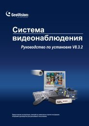
Installation Guide for<br />
<strong>GeoVision</strong> Surveillance System<br />
Welcome to Installation Guide for <strong>GeoVision</strong> Surveillance System<br />
This manual provides <strong>the</strong> following instructional aids to guide you through <strong>the</strong><br />
installation of <strong>GeoVision</strong> Surveillance System:<br />
• Video Capture Cards<br />
• Hardware Accessories<br />
• Software Installation<br />
• Overview of Main Screens<br />
• Troubleshooting
Table of Contents<br />
Chapter 1 Video Capture Cards<br />
1.1 GV-1120, 1240, 1480 .................... 2<br />
1.2 GV-650, 800 .................... 5<br />
1.3 GV-600 .................... 9<br />
1.4 GV-250 .................... 13<br />
1.5 Installing Drivers .................... 17<br />
1.6 Connecting Hardware Watchdog .................... 19<br />
1.7 Comparison Chart .................... 20<br />
Chapter 2 Hardware Accessories<br />
2.1 GV-Hybrid Card .................... 24<br />
2.2 GV-Loop Through Card .................... 27<br />
2.3 GV-DSP Card .................... 29<br />
2.4 GV-A16 Card .................... 32<br />
2.5 GV-Net Card .................... 34<br />
2.6 GV-Net/IO Card .................... 37<br />
2.7 GV-IO 12-In Card .................... 41<br />
2.8 GV-IO 12-Out Card .................... 44<br />
2.9 GV-Net Box .................... 47<br />
2.10 GV-I/O and GV-Relay Module .................... 49<br />
2.11 GV-Hub Box .................... 52<br />
2.12 GV-COM Box .................... 56<br />
2.13 GV-Data Capture V2 Box .................... 59<br />
2.14 GV-Data Capture V2E Box .................... 59<br />
2.15 GV-Keyboard .................... 60<br />
2.16 GV-IR Remote Control .................... 60
Chapter 3 Software Installation<br />
3.1 Before You Start .................... 62<br />
3.2 Installing <strong>the</strong> System .................... 63<br />
3.3 Program List .................... 65<br />
Chapter 4 Screen Overview<br />
4.1 Main System .................... 68<br />
4.2 ViewLog .................... 70<br />
4.3 Remote Playback Client .................... 74<br />
4.4 SingleView MPEG4 Encoder Viewer .................... 76<br />
4.5 MultivView MPEG4 Encoder Viewer .................... 78<br />
4.6 Remote Playback on WebCam .................... 80<br />
4.7 Center V2 .................... 82<br />
4.8 Control Center Toolbar .................... 84<br />
Troubleshooting.................................................................... 85
Chapter 1<br />
Video Capture Cards<br />
This chapter includes <strong>the</strong> following information:<br />
• Minimum system requirements<br />
• Packing list<br />
• Connection diagrams<br />
• Specifications<br />
• Driver installation<br />
• Comparison chart
1.1 GV-1120, 1240, 1480<br />
GV-1120, GV-1240 and GV-1480 are a three-in-one combo card including <strong>the</strong><br />
features of previous GV-Video Capture Card, GV-DSP Card and GV-A16 Card.<br />
GV-1120, GV-1240 and GV-1480 provide a single card solution for video and audio<br />
recording, as well as real-time display.<br />
Minimum System Requirements<br />
OS Windows 2000 / Windows XP / Windows Server 2003<br />
CPU<br />
GV-1120 Pentium 4-2.4C GHz, 800 MHz FSB<br />
GV-1240 Pentium 4-2.6C GHz, 800 MHz FSB<br />
GV-1480 Pentium 4-2.8C GHz, 800 MHz FSB<br />
RAM 2 x 256 MB Dual DDR400 SDRAM<br />
HDD<br />
GV-1120 80 GB<br />
GV-1240 120 GB<br />
GV-1480 250 GB<br />
VGA ATI Radeon 9550 or above (Recommended)<br />
DirectX 9.0 or above<br />
Note:<br />
1. For recording resolution of 640 x 480 or above, Pentium 4 processor with Hyper<br />
Threading is required.<br />
2. Currently GV-Video Capture Cards are not compatible with VIA-series chipset<br />
mo<strong>the</strong>rboards.<br />
Packing List<br />
2<br />
1 GV-1120/1240/1480 Combo Card x 1<br />
2 Audio Extension Card x 1<br />
3 1-8 D-Type Video Cable x 1<br />
4 9-16 D-Type Video Cable x 1<br />
5 1-8 D-Type Audio Cable x 1<br />
6 9-16 D-Type Audio Cable x 1<br />
7 Installation Guide x1<br />
8 Software CD x 1<br />
9 Feature Guide x 1<br />
10 Hardware Watchdog Jumper<br />
Wire x 1
Connections<br />
1<br />
Video Capture Cards<br />
• Plug <strong>the</strong> Audio Extension Card in <strong>the</strong> assigned connectors on <strong>the</strong> GV-Combo<br />
card.<br />
• Connect D-Type video and audio cables to <strong>the</strong> GV-Combo Card and Audio<br />
Extension Card respectively.<br />
• Connect <strong>the</strong> TV monitor to <strong>the</strong> GV-Combo Card if needed.<br />
Video 1~8<br />
Video 9~16<br />
Audio 1~8<br />
Audio 9~16<br />
3<br />
1-8 D-Type<br />
Video Cable<br />
4<br />
9-16 D-Type<br />
Video Cable<br />
5<br />
1-8 D-Type<br />
Audio Cable<br />
6<br />
9-16 D-Type<br />
Audio Cable<br />
TV Monitor<br />
1<br />
2<br />
GV-Combo Card<br />
1<br />
3<br />
2<br />
4<br />
Audio Extension Card<br />
Figure 1-1 GV-Combo Card connections<br />
1<br />
2<br />
3<br />
4<br />
3
Specifications<br />
GV-1120 GV-1240 GV-1480<br />
Input Type DB15 x 2 (Video), DB9 x 2 (Audio)<br />
Video Input 8, 12, 16 Cams 8, 16 Cams 16 Cams<br />
Audio Input 8, 12, 16 Channels 8, 16 Channels 16 Channels<br />
TV Output RCA connector x 1<br />
Recording Rate<br />
Display Rate<br />
Video<br />
Resolution<br />
NTSC 120 fps 240 fps 480 fps<br />
PAL 100 fps 200 fps 400 fps<br />
NTSC 480 fps<br />
PAL 400 fps<br />
NTSC 720 x 480, 720 x 480 De-interlace, 720 x 240, 640 x 480,<br />
640 x 480 De-interlace, 640 x 240, 320 x 240<br />
PAL 720 x 576, 720 x 576 De-interlace, 720 x 288, 640 x 480,<br />
640 x 480 De-interlace, 640 x 240, 320 x 240<br />
Compression Format Wavelet, MPEG-4, Geo MPEG4,<br />
GV-NET/IO Card Support Yes<br />
GV-Hybrid DVR Card<br />
Support<br />
Geo MPEG4 (ASP), Geo H.264<br />
Yes<br />
Dimensions (W x H) 195 mm x 100 mm<br />
4
1.2 GV-650, 800<br />
1<br />
Video Capture Cards<br />
The GV-650 and GV-800 Card have <strong>the</strong> same appearance, system requirements<br />
and packing list so that we introduce both toge<strong>the</strong>r in this section. However, you<br />
may choose between <strong>the</strong> two according to your need for recording rate and audio<br />
channels.<br />
Minimum System Requirements<br />
OS Windows 2000 / Windows XP / Windows Server 2003<br />
CPU Pentium 4-2.0 GHz<br />
RAM 256 MB DDR SDRAM<br />
HDD 80 GB<br />
VGA NVIDIA GeForce 2 MX200 32 MB (Recommended)<br />
DirectX 9.0 or above<br />
Note: Currently GV-Video Capture Cards are not compatible with VIA- series<br />
Packing List<br />
chipset mo<strong>the</strong>rboards.<br />
1 GV-800 or GV-650 Card x 1<br />
2 Audio Extension Card x 1 **<br />
3 1-8 Cams with 4-Port Audio D-Type<br />
Cable x 1<br />
4 9-16 Cams D-Type Cable x 1 *<br />
5 BNC Video Extension Card ***<br />
(Quantity depends on model purchased)<br />
* Supplied with 12-16 Cams D-Type Video Capture Card<br />
** Supplied with BNC Video Capture Card<br />
*** Supplied with 8-16 Cams BNC Video Capture Card<br />
6 Hardware Watchdog Jumper<br />
Wire x 1<br />
7 Software CD x 1<br />
8 Feature Guide x 1<br />
9 Installation Guide x1<br />
5
Connections<br />
6<br />
There are two types of GV-800 and GV-650 Cards: BNC and D-type. BNC type only<br />
provides four video channels; video and audio extension cards are required for<br />
extension. D-type can provide up to 16 video channels and four audio channels<br />
toge<strong>the</strong>r.<br />
For <strong>the</strong> D-type video capture card, plug <strong>the</strong> black video/audio cable into <strong>the</strong> black<br />
connector on <strong>the</strong> GV-650/800 Card; <strong>the</strong> blue video cable into <strong>the</strong> blue connector, as<br />
illustrated below.<br />
Note: The GV-650 Card only supports two audio channels so that only two audio<br />
Video 1~8 (Black)<br />
Audio 1~4 (White)<br />
ports can work in <strong>the</strong> supplied 1-8 Cams with 4-Port Audio D-Type cable.<br />
Video 9~16 (Blue)<br />
Figure 1-2 D-type GV-650 or GV-800 Card connections<br />
GV-800/650 Card
1<br />
Video Capture Cards<br />
For <strong>the</strong> BNC-type video capture card, plug <strong>the</strong> Audio Extension Card into No. 1 or<br />
No. 2 connector on <strong>the</strong> GV-650/800 Card, as illustrated below. Both connectors are<br />
okay for connection.<br />
1<br />
or<br />
2<br />
Audio Extension Card<br />
GV-800/650 Card<br />
Figure 1-3 BNC-type GV-650 or GV-800 Card connections<br />
7
Specifications<br />
Input Type<br />
BNC BNC x 4<br />
GV-650 GV-800<br />
D-type DB15 x 2<br />
Video Input 4, 8, 12, 16 Cams<br />
Audio Input 2 Channels 4 Channels<br />
Recording Rate<br />
Display Rate<br />
Video Resolution<br />
NTSC 60 fps 120 fps<br />
PAL 50 fps 100 fps<br />
NTSC 60 fps 120 fps<br />
PAL 50 fps 100 fps<br />
NTSC 720 x 480, 720 x 480 De-interlace,<br />
720 x 240, 640 x 480, 640 x 480 De-interlace,<br />
640 x 240, 320 x 240<br />
PAL 720 x 576, 720 x 576 De-interlace,<br />
720 x 288, 640 x 480, 640 x 480 De-interlace,<br />
640 x 240,320 x 240<br />
Compression Format Wavelet, MPEG-4, Geo MPEG4,<br />
GV-DSP Card Support Yes<br />
GV-A16 Support Yes<br />
GV-NET/IO Card Support Yes<br />
Dimensions (W x H)<br />
8<br />
Geo MPEG4 (ASP), Geo H.264<br />
BNC 175 mm x 98 mm<br />
D-type 175 mm x 98 mm
1.3 GV-600<br />
1<br />
Video Capture Cards<br />
There are two types of GV-600 Cards: BNC and D-type. BNC type only provides<br />
four video channels; video and audio extension cards are required for extension.<br />
D-type can provide up to 16 video channels and one audio channel toge<strong>the</strong>r.<br />
Minimum System Requirements<br />
OS Windows 2000 / Windows XP / Windows Server 2003<br />
CPU Pentium 4-2.0 GHz<br />
RAM 256 MB DDR SDRAM<br />
HDD 80 GB<br />
VGA NVIDIA GeForce 2 MX200 32 MB (Recommended)<br />
DirectX 9.0 or above<br />
Note: Currently GV-Video Capture Cards are not compatible with VIA- series<br />
Packing List<br />
chipset mo<strong>the</strong>rboards.<br />
1 GV-600 Card x 1<br />
2 Audio Extension Card x 1 **<br />
3 1-8 Cams with 4-Port Audio D-Type<br />
Cable x 1<br />
4 9-16 Cams D-Type Cable x 1 *<br />
5 BNC Video Extension Card ***<br />
(Quantity depends on model purchased)<br />
6 Hardware Watchdog Jumper<br />
Wire x 1<br />
* Supplied with 10-16 Cams D-Type Video Capture Card<br />
** Supplied with BNC Video Capture Card<br />
*** Supplied with 6-16 Cams BNC Video Capture Card<br />
7 Software CD x 1<br />
8 Feature Guide x 1<br />
9 Installation Guide x1<br />
9
Connections<br />
10<br />
For <strong>the</strong> D-type video capture card, plug <strong>the</strong> black video/audio cable into <strong>the</strong> black<br />
connector on <strong>the</strong> GV-600 Card; <strong>the</strong> blue video cable into <strong>the</strong> blue connector, as<br />
illustrated below.<br />
Note: The GV-600 Card only supports one audio channel so that only one audio<br />
port can work in <strong>the</strong> supplied 1-8 Cams with 4-Port Audio D-Type cable.<br />
Video 1~8 (Black)<br />
Audio 1~4 (White)<br />
Video 9~16 (Blue)<br />
Figure 1-4 D-type GV-600 Card connections<br />
GV-600 Card
1<br />
Video Capture Cards<br />
For <strong>the</strong> BNC-Type video capture card, plug <strong>the</strong> Audio Extension Card into No. 1 or<br />
No. 2 connector on <strong>the</strong> GV-600 Card, as illustrated below. Both connectors are<br />
okay for connection.<br />
or<br />
1<br />
2<br />
Audio Extension Card<br />
GV-600 Card<br />
Figure 1-5 BNC-type GV-600 Card connections<br />
11
Specifications<br />
GV-600<br />
Input Type<br />
GV-600 BNC: BNC x 4<br />
GV-600 D-type: DB15 x 2<br />
Video Input 4, 6, 8, 10, 12, 14, 16 Cams<br />
Audio Input 1 Channel<br />
Recording Rate<br />
Display Rate<br />
Video Resolution<br />
NTSC 30 fps<br />
PAL 25 fps<br />
NTSC 30 fps<br />
PAL 25 fps<br />
NTSC 720 x 480, 720 x 480 De-interlace, 720 x 240,<br />
640 x 480, 640 x 480 De-interlace, 640 x 240,<br />
320 x 240<br />
PAL 720 x 576, 720 x 576 De-interlace, 720 x 288,<br />
640 x 480, 640 x 480 De-interlace, 640 x 240,<br />
320 x 240<br />
Compression Format Wavelet, MPEG-4, Geo MPEG4,<br />
GV-DSP Card Support Yes<br />
GV-A16 Support Yes<br />
GV-NET/IO Card Support Yes<br />
Dimensions (W x H)<br />
12<br />
Geo MPEG4 (ASP), Geo H.264<br />
BNC 145 mm x 97 mm<br />
D-type 145 mm x 97 mm
1.4 GV-250<br />
1<br />
Video Capture Cards<br />
There are two types of GV-250 Cards: BNC and D-type. BNC type only provides<br />
four video channels; video and audio extension cards are required for extension.<br />
D-type can provide up to 16 video channels and one audio channel toge<strong>the</strong>r.<br />
Minimum System Requirements<br />
OS Windows 2000 / Windows XP / Windows Server 2003<br />
CPU Pentium 4-2.0 GHz<br />
RAM 256 MB DDR SDRAM<br />
HDD 80 GB<br />
VGA NVIDIA GeForce 2 MX200 32 MB (Recommended)<br />
DirectX 9.0 or above<br />
Note: Currently GV-Video Capture Cards are not compatible with VIA- series<br />
Packing List<br />
chipset mo<strong>the</strong>rboards.<br />
1 GV-250 Card x 1<br />
2 Audio Extension Card x 1 **<br />
3 1-8 Cams with 4-Port Audio D-Type<br />
Cable x 1<br />
4 9-16 Cams D-Type Cable x 1 *<br />
5 BNC Video Extension Card ***<br />
(Quantity depends on model purchased)<br />
6 Hardware Watchdog Jumper<br />
Wire x 1<br />
* Supplied with 12-16 Cams D-Type Video Capture Card<br />
** Supplied with BNC Video Capture Card<br />
*** Supplied with 6-16 Cams BNC Video Capture Card<br />
7 Software CD x 1<br />
8 Feature Guide x 1<br />
9 Installation Guide x1<br />
13
Connections<br />
14<br />
For <strong>the</strong> D-type video capture card, plug <strong>the</strong> black video/audio cable into <strong>the</strong> black<br />
connector on <strong>the</strong> GV-250 Card; <strong>the</strong> blue video cable into <strong>the</strong> blue connector, as<br />
illustrated below.<br />
Note: The GV-250 Card only supports one audio channel so that only one audio<br />
port can work in <strong>the</strong> supplied 1-8 Cams with 4-Port Audio D-Type cable.<br />
Video 1~8 (Black)<br />
Audio 1~4 (White)<br />
Video 9~16 (Blue)<br />
Figure1- 6 D-type GV-250 Card connections<br />
GV-250
1<br />
Video Capture Cards<br />
For <strong>the</strong> BNC-type video capture card, plug <strong>the</strong> Audio Extension Card into <strong>the</strong><br />
connector on <strong>the</strong> GV-250 Card, as illustrated below.<br />
GV-250 Card<br />
Figure 1-7 BNC-type GV-250 Card connections<br />
Audio Extension Card<br />
15
Specifications<br />
GV-250<br />
Input Type<br />
GV-250 BNC: BNC x 4<br />
GV-250 D-type: DB15 x 2<br />
Video Input 1, 2, 4, 6, 8,12,16 Cams<br />
Audio Input 1 Channel<br />
Recording Rate<br />
Display Rate<br />
Video Resolution<br />
Compression Format<br />
NTSC 15 fps<br />
PAL 12 fps<br />
NTSC 15 fps<br />
PAL 12 fps<br />
GV-DSP Card Support Yes<br />
GV-A16 Support No<br />
GV-NET/IO Card Support No<br />
Dimensions (W x H)<br />
16<br />
NTSC 720 x 480, 720 x 480 De-interlace, 720 x 240,<br />
640 x 480, 640 x 480 De-interlace, 640 x 240,<br />
320 x 240<br />
PAL 720 x 576, 720 x 576 De-interlace, 720 x 288,<br />
640 x 480, 640 x 480 De-interlace, 640 x 240,<br />
320 x 240<br />
Wavelet, MPEG-4, Geo MPEG4,<br />
Geo MPEG4 (ASP), Geo H.264<br />
BNC 120 mm x 95 mm<br />
D-type 125 mm x 87 mm
1.5 Installing Drivers<br />
1<br />
Video Capture Cards<br />
After you install <strong>the</strong> GV-Video Capture Card on <strong>the</strong> computer, <strong>the</strong> Found New<br />
Hardware Wizard will automatically detect <strong>the</strong> device. Ignore <strong>the</strong> wizard and follow<br />
<strong>the</strong>se steps to install drivers:<br />
1. Insert <strong>the</strong> software CD. It will run automatically and pop up a window.<br />
2. Select Install or Remove GV-Series Driver, and <strong>the</strong>n click Install or Remove<br />
GV-Series Cards Driver. This displays this dialog box.<br />
3. Click Install to install <strong>the</strong> drivers. When <strong>the</strong> installation is complete, this<br />
message will appear: Install Successfully.<br />
4. Click Exit to close <strong>the</strong> dialog box.<br />
Note: In Windows XP, <strong>the</strong> wizard will disappear after installation. In Windows<br />
2000, close <strong>the</strong> wizard manually.<br />
17
18<br />
To verify <strong>the</strong> drivers are installed correctly, go to Device Manager and see if <strong>the</strong><br />
following entries are listed.<br />
Expand <strong>the</strong> Sound, video and game controller field, you can see:<br />
Model Entry<br />
GV-250 GV250 Audio<br />
GV250 Video Capture<br />
GV-600-4 GV600_4 or GV604(S) Video Capture # A<br />
GV600_4 or GV604(S) Audio # A<br />
GV-600 GV600V2, GV600V3 or GV600(S) Audio # A<br />
GV600V2 ,GV600V3 or GV600(S) Video Capture # A<br />
GV-650 GV650, GV650V3 or GV650(S) Audio # A - # B<br />
GV650, GV650V3 or GV650(S) Video Capture # A - # B<br />
GV-800-4 GV800_4 or GV804(S) Video Capture # A - # D<br />
GV800_4 or GV804(S) Audio # A - # D<br />
GV-800 GV800V2, GV800V3 or GV800(S) Audio # A - # D<br />
GV800V2, GV800V3 or GV800(S) Video Capture # A - # D<br />
Expand <strong>the</strong> DVR-Devices field, you can see:<br />
Model Entry<br />
GV-1120 GV1480 Series<br />
GV-1240 GV1480 Series<br />
GV-1480 GV1480 Series
1.6 Connecting Hardware Watchdog<br />
1<br />
Video Capture Cards<br />
To reboot <strong>the</strong> computer by <strong>the</strong> hardware watchdog on <strong>the</strong> GV-Video Capture Card,<br />
a connection needs to be made from <strong>the</strong> card to <strong>the</strong> mo<strong>the</strong>rboard.<br />
1. Using <strong>the</strong> supplied jumper wire, connect <strong>the</strong> reset jumper pins on <strong>the</strong> card and<br />
on <strong>the</strong> mo<strong>the</strong>rboard.<br />
<strong>GeoVision</strong> GV-600v2<br />
PC Reset Switch<br />
RST<br />
HDD<br />
+ _<br />
PWSW<br />
LED<br />
GV-600 v2 Mo<strong>the</strong>rboard<br />
Front Panel Jumper<br />
Figure 1-8 Watchdog connections<br />
2. If <strong>the</strong> computer has a reset switch, <strong>the</strong> switch’s jumper wire should already be<br />
connected to <strong>the</strong> mo<strong>the</strong>rboard’s reset jumper pins. Remove <strong>the</strong> switch wire from<br />
<strong>the</strong> mo<strong>the</strong>rboard and connect it to <strong>the</strong> reset jumper pins on <strong>the</strong> card.<br />
19
1.7 Comparison Chart<br />
GV-250 GV-600 GV-650<br />
Input Type BNC / D-Type BNC / D-Type BNC / D-Type<br />
Video Input 1, 2, 4, 6, 8, 12, 16 4, 6, 8, 10, 12, 14, 16 4, 8, 12, 16<br />
NTSC 15 fps 30 fps 60 fps<br />
Total Recording Rate PAL 12 fps 25 fps 50 fps<br />
Display Rate<br />
NTSC 15 fps 30 fps 60 fps<br />
PAL 12 fps 25 fps 50 fps<br />
Video Codec Wavelet, MPEG-4, Geo MPEG4, Geo MPEG4 (ASP), Geo H.264<br />
Video Resolution<br />
NTSC<br />
PAL<br />
720 x 480, 720 x 480 De-interlace,720 x 240, 640 x 480,<br />
640 x 480 De-interlace, 640 x 240, 320 x 240<br />
720 x 576, 720 x 576 De-interlace, 720 x 288, 640 x 480,<br />
640 x 480 De-interlace, 640 x 240, 320 x 240<br />
Audio Input 1 1 2<br />
Audio Codec ADPCM 8Khz 4 bit Mono<br />
GV-DSP Support O O O<br />
GV-A16 Support X O O<br />
GV-Hybrid DVR Card Support X O O<br />
GV-NET/IO Card Support X O O<br />
GV-I/O 12-In Card Support X O O<br />
GV-I/O 12-Out Card Support X O O<br />
GV-I/O Support O O O<br />
Hardware Watchdog X O O<br />
Minimum System Requirements<br />
OS Windows 2000 / Windows XP / Windows Server 2003<br />
Direct X 9.0 or above<br />
CPU Pentium 4 - 2.0 GHz<br />
RAM 256MB DDR SDRAM<br />
HDD 80 GB<br />
VGA NVIDIA GeForce 2 MX200 32MB<br />
Note:<br />
1. Currently GV-series video capture cards are not compatible with VIA-series chipset<br />
mo<strong>the</strong>rboards.<br />
2. For recording resolution of 640 x 480 or above, Pentium 4 processor with Hyper<br />
Threading is required.<br />
20
1<br />
Video Capture Cards<br />
GV-800 GV-1120 GV-1240 GV-1480<br />
BNC / D-Type D-Type D-Type D-Type<br />
4, 8, 12, 16 8, 12, 16 8, 16 16<br />
120 fps 120 fps 240 fps 480 fps<br />
100 fps 100 fps 200 fps 400 fps<br />
120 fps 480 fps 480 fps 480 fps<br />
100 fps 400 fps 400 fps 400 fps<br />
Wavelet, MPEG-4, Geo MPEG4, Geo MPEG4 (ASP),Geo H.264<br />
720 x 480, 720 x 480 De-interlace,720 x 240, 640 x 480, 640 x 480 De-interlace,<br />
640 x 240, 320 x 240<br />
720 x 576, 720 x 576 De-interlace, 720 x 288, 640 x 480, 640 x 480 De-interlace,<br />
640 x 240, 320 x 240<br />
4 8, 12, 16 8, 16 16<br />
ADPCM 8Khz 4 bit Mono<br />
O X X X<br />
O X X X<br />
O O O O<br />
O O O O<br />
O O O O<br />
O O O O<br />
O O O O<br />
O O O O<br />
Minimum System Requirements<br />
Windows 2000 / Windows XP / Windows Server 2003<br />
9.0 or above<br />
Pentium 4 - 2.0 GHz Pentium 4 - 2.4C GHz Pentium 4 - 2.6C GHz Pentium 4 - 2.8C GHz<br />
256MB DDR SDRAM 2 x 256MB Dual DDR400 SDRAM<br />
NVIDIA GeForce 2<br />
MX200 32MB<br />
80 GB 120 GB 250 GB<br />
ATI Radeon 9550 or above (Recommended)<br />
21
Chapter 2<br />
Hardware Accessories<br />
This chapter includes <strong>the</strong> following information:<br />
• System requirements<br />
• Packing list<br />
• Connection diagrams<br />
• Specifications<br />
• Driver installation
2.1 GV-Hybrid DVR Card<br />
The GV-Hybrid DVR Card supports hardware-based compression, giving you less<br />
CPU usage and higher system performance. It features:<br />
• DVD recording quality.<br />
• Support for exporting DVD format files.<br />
The Characteristics of GV-Hybrid DVR Card<br />
• You can connect up to four GV-Hybrid DVR Cards to one GV-System; one<br />
GV-Hybrid DVR Card supports up to four channels.<br />
• The GV-Hybrid DVR Card only affects video recording; all live views are still<br />
provided by <strong>the</strong> GV-Video Capture Card.<br />
• For audio recording, <strong>the</strong> audio inputs of <strong>the</strong> GV-Video Capture Card always<br />
have <strong>the</strong> sequence priority over those of GV-Hybrid DVR Card. For example,<br />
GV-800 Card has 4 audio channels, so that <strong>the</strong> GV-Hybrid DVR Card’s audio<br />
channels will be from 5 to upwards.<br />
• The GV-Hybrid DVR Card supported-channels do not work with <strong>the</strong>se features:<br />
Water Mark, Text Overlay and Pre-Rec Motion.<br />
For fur<strong>the</strong>r operations on GV-System, see Configuring Hybrid Cameras, Chapter 1,<br />
User’s Manual on <strong>the</strong> Surveillance System Software CD.<br />
System Requirements<br />
• GV-600, 650, 750, 800, 1000, 1120, 1240 and 1480 Cards<br />
• Version 7.0 or later<br />
Packing List<br />
24<br />
1 GV-Hybrid DVR Card x 1<br />
2 Hardware Watchdog Jumper Wire x 1<br />
3 5-Pin to 5-Pin Audio Cable x 1<br />
4 2-Pin to 5-Pin Audio Cable x 1<br />
5 40-Pin Ribbon Cable x 1<br />
6 Installation Guide x 1
Connections<br />
2<br />
Hardware Accessories<br />
Connect <strong>the</strong> GV-Hybrid DVR Card to <strong>the</strong> GV-Video Capture Card as illustrated<br />
below.<br />
Note: Make sure <strong>the</strong> Ribbon Cables are connected to <strong>the</strong> correct input and<br />
output on <strong>the</strong> GV-Hybrid DVR Card.<br />
GV Video Capture Card<br />
Audio Inputs<br />
ON<br />
3 4<br />
1 2<br />
Input Output<br />
1<br />
2 40-Pin Ribbon Cable<br />
GV-Hybrid DVR Card<br />
Figure 2-1 GV-Hybrid DVR Card connections<br />
Connects to <strong>the</strong> input of<br />
<strong>the</strong> 2 nd GV-Hybrid DVR<br />
Card or GV-DSP Card<br />
25
Installing Drivers<br />
After you install <strong>the</strong> GV-Hybrid DVR Card to <strong>the</strong> computer, <strong>the</strong> Hardware Wizard<br />
will automatically detect <strong>the</strong> device. Ignore <strong>the</strong> wizard, and follow <strong>the</strong> steps in 1.5<br />
Installing Drivers, Chapter 1 to install drivers.<br />
To verify <strong>the</strong> drivers are installed correctly, go to Device Manager. In <strong>the</strong><br />
DVR-Devices field, you should see 4 entries for GVMP2 and 11 entries for GVMP2<br />
Null, as shown below.<br />
Specifications<br />
26<br />
Figure 2-2 Verifying GV-Hybrid DVR Card’s drivers<br />
Interface 40-Pin Connector<br />
Audio Input RCA Connector x 4<br />
Number of Channels 4<br />
Recording Rate 120 fps (NTSC), 100 fps (PAL)<br />
Video Resolution<br />
NTSC: 720 x 480<br />
PAL: 720 x 576<br />
Dimensions 180 mm x 102 mm
2.2 GV-Loop Through Card<br />
2<br />
Hardware Accessories<br />
The GV-Loop Through Card is designed to take <strong>the</strong> video signal directly from <strong>the</strong><br />
GV-Video Capture Card, without internal device processes, and <strong>the</strong>n split it into 16<br />
signals while maintaining video quality. With <strong>the</strong> duplicate 16 signals, <strong>the</strong> card can<br />
meet your need for multiple monitors.<br />
Packing List<br />
1 GV-Loop Through Card x 1<br />
2 1-8 D-Type Video Cable x 1<br />
3 9-16 D-Type Video Cable x 1<br />
Overview<br />
Note:<br />
No. 1<br />
IN<br />
OUT<br />
4 40-Pin Ribbon Cable x 1<br />
5 Installation Guide x 1<br />
No. 3<br />
No. 2<br />
No. 1: Video OUT<br />
No. 2: Video OUT<br />
No. 3: Video IN/OUT (IN for GV Video Capture Card, OUT for DSP Card or<br />
Hybrid DVR Card.)<br />
Figure 2-3 GV-Loop Through Card<br />
1. For No. 2 Video Out, an extra D-Type extension card is required.<br />
2. Select ei<strong>the</strong>r No. 1 or No. 2 for video out. Using both at <strong>the</strong> same time may<br />
cause video degradation.<br />
3. Only connect GV-series cards, such as Video Capture Card, DSP Card or<br />
Hybrid DVR Card to No. 3. O<strong>the</strong>r devices are prohibited.<br />
27
Connections<br />
Connect D-type cables and <strong>the</strong> GV-Video Capture Card to <strong>the</strong> GV-Loop Through<br />
Card as illustrated below.<br />
Video out 1~8<br />
(Loop out)<br />
Video out 9~16<br />
(Loop out)<br />
Specifications<br />
28<br />
GV Video Capture Card<br />
2<br />
1-8 D-Type<br />
Video Cable<br />
3 9-16 D-Type<br />
Video Cable<br />
1<br />
GV-Loop Through Card<br />
Figure 2-4 GV-Loop Through Card connections<br />
Interface for GV-Video Capture Card 40-Pin Connector x 2<br />
Output Interface<br />
DB15 Connector x 2<br />
40-Pin Connector x 1<br />
Input Signal 16 Channels<br />
Dimensions 130 mm x 98 mm<br />
4<br />
40-Pin<br />
Ribbon Cable
2.3 GV-DSP Card<br />
2<br />
Hardware Accessories<br />
The GV-DSP Card, a real-time display card, enables <strong>the</strong> live display up to 480 fps.<br />
In addition, <strong>the</strong> card supports a TV output, allowing for <strong>the</strong> simultaneous display on<br />
computer and a TV monitor (spot monitor).<br />
For fur<strong>the</strong>r operations in GV-System, see DSP Spot Monitor Controller, Chapter 1,<br />
User’s Manual on <strong>the</strong> Surveillance System Software CD.<br />
System Requirements<br />
• At least a GeForce 2 MX200 VGA card<br />
Note: The GV-DSP Card is not compatible with VIA-series chipset<br />
Packing List<br />
mo<strong>the</strong>rboards.<br />
1 GV-DSP Card x 1<br />
2 40-Pin Ribbon Cable x 1<br />
3 Installation Guide x 1<br />
29
Connections<br />
30<br />
Use <strong>the</strong> supplied Ribbon Cable to connect <strong>the</strong> GV-DSP Card to <strong>the</strong> GV-Video<br />
Capture Card as illustrated below.<br />
TV Monitor<br />
GV Video Capture Card<br />
1<br />
GV-DSP Card<br />
Figure 2-5 GV-DSP Card connections<br />
2 40-Pin<br />
Ribbon Cable
Installing Drivers<br />
2<br />
Hardware Accessories<br />
After you install <strong>the</strong> GV-DSP Card to <strong>the</strong> computer, <strong>the</strong> Hardware Wizard will<br />
automatically detect <strong>the</strong> device. Ignore <strong>the</strong> wizard, and follow <strong>the</strong> steps in 1.5<br />
Installing Drivers to install drivers.<br />
To verify <strong>the</strong> drivers are installed correctly, go to Device Manager. Expanding <strong>the</strong><br />
Sound, video and game controllers field, you can see:<br />
Model Entry<br />
Figure 2-6 Verifying GV-DSP 16-port Card drivers<br />
8-port GVDSP8P Audio, GVDSP8P Video Capture<br />
16-port GVDSP Audio #A, GVDSP Video Capture #A<br />
Specifications<br />
Interface 40-Pin Connector<br />
TV Output RCA Connector x 1<br />
Number of Channels 8, 16<br />
Display Rate<br />
Video Resolution<br />
GV-DSP-8 240 fps<br />
GV-DSP-16 480 fps<br />
NTSC 640 x 480<br />
PAL 720 x 576<br />
Compatible Model GV-250, GV-600, GV-650, GV-800, GV-900, GV-1000<br />
Dimensions<br />
GV-DSP-8 191 mm x 98 mm<br />
GV-DSP-16 204 mm x 100 mm<br />
31
2.4 GV-A16 Card<br />
The GV-A16 Card can work with <strong>the</strong> GV-Video Capture Card to record audio for 16<br />
channels, and to provide full duplex audio communication between local and<br />
remote users.<br />
Packing List<br />
1 GV-A16 Card x 1<br />
2 1-8 D-Type Audio Cable x 1<br />
Connections<br />
32<br />
3 9-16 D-Type Audio Cable x 1<br />
4 Installation Guide x 1<br />
Connect <strong>the</strong> audio cables to <strong>the</strong> GV-A16 Card as illustrated below.<br />
2 1-8 D-Type<br />
Audio Cable<br />
3 9-16 D-Type<br />
Audio Cable<br />
Figure 2-7 GV-A16 Card Connections<br />
1<br />
GV-A16 Card
Installing Drivers<br />
2<br />
Hardware Accessories<br />
After you install <strong>the</strong> GV-A16 Card to <strong>the</strong> computer, <strong>the</strong> Hardware Wizard will<br />
automatically detect <strong>the</strong> device. Ignore <strong>the</strong> wizard, and follow <strong>the</strong> steps in 1.5<br />
Installing Drivers, Chapter 1 to install drivers.<br />
To verify <strong>the</strong> drivers are installed correctly, go to Device Manager. Expanding <strong>the</strong><br />
Sound, video and game controllers field, you should see <strong>the</strong> entries for GVA16<br />
Audio and GVA16 Video.<br />
Specifications<br />
Figure 2-8 Verifying GV-A16 Card drivers<br />
Interface DB9 Connector x 2<br />
Number of Channels 16<br />
Audio Compression ADPCM 8 bit Mono<br />
Compatible Model GV-600, GV-650, GV-800, GV-900, GV-1000<br />
Dimensions 120 mm x 91 mm<br />
33
2.5 GV-NET Card<br />
The GV-NET Card is a RS-485 to RS-232 interface converter. This Card connects<br />
to <strong>the</strong> RS-232 port on your computer, and allows RS-485 devices, such as PTZ<br />
domes, to be connected through <strong>the</strong> Card.<br />
Packing List<br />
1 GV-NET Card x 1<br />
2 RJ-11 to DB9 Cable x 1<br />
Connections<br />
3 4-Pin to 4-Pin Mini Power Cable x 1<br />
4 Installation Guide x 1<br />
Use <strong>the</strong> RJ-11 to DB9 Cable to connect <strong>the</strong> Card to <strong>the</strong> PC’s COM port. Use <strong>the</strong><br />
4-Pin Mini Power Cable to connect <strong>the</strong> Card to <strong>the</strong> PC’s power supply.<br />
Note: The GV-NET Card only provides RS-485 / RS-232 data conversion; <strong>the</strong><br />
Connects to<br />
PC's Com Port<br />
34<br />
connection to <strong>the</strong> GV-Video Capture Card is not required.<br />
2<br />
RS-485 +<br />
RS-485 -<br />
RJ-11 to DB9 Cable<br />
1<br />
GV-NET Card<br />
Figure 2-9 GV-Net Card Connections<br />
3 4-Pin Mini Power Cable<br />
Connects to PC's<br />
Power Supply
RS-485 Device Connections<br />
2<br />
Hardware Accessories<br />
Following provides three examples of connecting RS-485 devices to your computer<br />
through <strong>the</strong> GV-NET Card.<br />
Connecting PTZ Domes<br />
The GV-NET Card can connect up to 16 PTZ domes.<br />
PTZ Dome 1<br />
PTZ Dome 2<br />
Connecting <strong>the</strong> POS System<br />
PTZ Dome 16<br />
RS-485+<br />
RS-485-<br />
Figure 2-10 Connecting PTZ domes<br />
Use <strong>the</strong> GV-NET Card and <strong>the</strong> RS-485 cable to extend <strong>the</strong> communication distance<br />
from <strong>the</strong> GV-Data Capture Box to <strong>the</strong> GV-System.<br />
POS System<br />
RS-232<br />
GV-Data Capture<br />
RS-485+<br />
RS-485-<br />
GV-NET Card<br />
Figure 2-11 Connecting <strong>the</strong> POS System<br />
GV-System<br />
35
Connecting <strong>the</strong> GV-IO and GV-Relay Module<br />
The GV-NET Card can connect up to nine GV-IO and GV-Relay modules.<br />
For details on <strong>the</strong> GV-IO and GV-Relay module, see 2.10 GV-IO and GV-Relay<br />
Module.<br />
DI 1<br />
GND<br />
DI 2<br />
GND<br />
DI 3<br />
GND<br />
DI 4<br />
GND<br />
DI 5<br />
GND<br />
DI 6<br />
GND<br />
DI 7<br />
GND<br />
DI 8<br />
GND<br />
Module 1<br />
DI 1<br />
GND<br />
DI 2<br />
GND<br />
DI 3<br />
GND<br />
DI 4<br />
GND<br />
<strong>GeoVision</strong> GV-IO<br />
DI 5<br />
GND<br />
DI 6<br />
GND<br />
DI 7<br />
GND<br />
DI 8<br />
GND<br />
Module 2<br />
Specifications<br />
36<br />
<strong>GeoVision</strong> GV-IO<br />
DI 1<br />
GND<br />
DI 2<br />
GND<br />
DI 3<br />
GND<br />
DI 4<br />
GND<br />
DI 5<br />
GND<br />
DI 6<br />
GND<br />
DI 7<br />
GND<br />
DI 8<br />
GND<br />
RS-485-<br />
RS-485+<br />
DO 1-1<br />
DO 2-1<br />
DO 3-1<br />
DO 4-1<br />
DO 5-1<br />
DO 6-1<br />
DO 7-1<br />
DO 8-1<br />
DO 1-2<br />
DO 2-2<br />
DO 3-2<br />
DO 4-2<br />
DO 5-2<br />
DO 6-2<br />
DO 7-2<br />
DO 8-2<br />
Module 9<br />
RS-485-<br />
RS-485+<br />
DO 1-1<br />
DO 2-1<br />
DO 3-1<br />
DO 4-1<br />
DO 5-1<br />
DO 6-1<br />
DO 7-1<br />
DO 8-1<br />
DO 1-2<br />
DO 2-2<br />
DO 3-2<br />
DO 4-2<br />
DO 5-2<br />
DO 6-2<br />
DO 7-2<br />
DO 8-2<br />
<strong>GeoVision</strong> GV-IO<br />
RS-485-<br />
RS-485+<br />
DO 1-1<br />
DO 2-1<br />
DO 3-1<br />
DO 4-1<br />
DO 5-1<br />
DO 6-1<br />
DO 7-1<br />
DO 8-1<br />
DO 1-2<br />
DO 2-2<br />
DO 3-2<br />
DO 4-2<br />
DO 5-2<br />
DO 6-2<br />
DO 7-2<br />
DO 8-2<br />
RS-485+<br />
RS-485-<br />
Figure 2-12 Connecting GV-IO boxes<br />
RS-232 to PC RJ-11 to DB9 Cable<br />
RS-485 Interface Two Wires<br />
Communication RS-485, 1,200-19,200 bps<br />
DC IN DC 5V, 1A<br />
Environmental Condition 0 to 50 Degree C, 5%-95% (Non-Condensing)<br />
Compatible Model <strong>All</strong> GV-Video Capture Card Models<br />
Dimensions 63 mm x 90 mm
2.6 GV-NET/IO Card<br />
2<br />
Hardware Accessories<br />
The GV-NET/IO Card not only is a RS-485 / RS-232 interface converter, but also<br />
supports four digital inputs and four relay outputs, meeting your need for external<br />
alarms and sensors.<br />
Packing List<br />
1 GV-NET/IO Card x 1<br />
2 RJ-11 to DB9 Cable x 1<br />
3 4-Pin to 4-Pin Mini Power Cable x 1<br />
4 20-Pin Ribbon Cable x 1<br />
5 Installation Guide x 1<br />
37
Connections<br />
• Use <strong>the</strong> Ribbon Cable to connect <strong>the</strong> GV-NET/IO Card to <strong>the</strong> GV-Video Capture<br />
Card.<br />
• Use <strong>the</strong> RJ-11 to DB9 Cable to connect <strong>the</strong> GV-NET/IO Card to <strong>the</strong> PC’s COM<br />
port.<br />
• Use <strong>the</strong> 4-Pin Mini Power Cable to connect <strong>the</strong> GV-NET/IO Card to <strong>the</strong> PC’s<br />
power supply.<br />
Relay Output 1~4<br />
Com<br />
Sensor Input 1~4<br />
Ground<br />
RS-485 Device<br />
Connects to<br />
PC's Com Port<br />
38<br />
Note:<br />
2<br />
RJ-11 to DB9 Cable<br />
1<br />
GV Video Capture Card<br />
GV-NET I/O Card<br />
Figure 2-13 GV-NET/IO Card connections<br />
1. Use <strong>the</strong> switch for Dry Contact and 5V Wet Contact.<br />
3<br />
4 20-Pin Ribbon Cable<br />
4-Pin Mini Power Cable<br />
Connects to PC's<br />
Power Supply<br />
2. The GV-NET/IO Card accepts ei<strong>the</strong>r all dry-contact or all wet-contact devices.<br />
Don’t mix two type devices in <strong>the</strong> same card.<br />
3. To prevent noise interference in I/O operation, tightly screw <strong>the</strong> GV-NET/IO<br />
Card to <strong>the</strong> computer case.
Connecting Output Devices<br />
Electronic<br />
Door Locks<br />
Connecting Input Devices<br />
Magnetic Contact<br />
Connecting RS-485 Devices<br />
FIRE<br />
Alarms<br />
Out 1<br />
Out 4<br />
COM<br />
Figure 2-14 Connecting output devices<br />
Motion Sensors<br />
IN 1<br />
IN 4<br />
GUD<br />
2<br />
Hardware Accessories<br />
OFF<br />
ON<br />
1 2<br />
Wet Contact<br />
Figure 2-15 Connecting input devices<br />
ON<br />
1 2<br />
ON<br />
1 2<br />
ON<br />
ON<br />
1 2<br />
Dry Contact<br />
The connections of RS-485 devices to <strong>the</strong> GV-NET/IO Card are <strong>the</strong> same as <strong>the</strong><br />
GV-NET Card. Refer to <strong>the</strong> diagrams in 2.5 GV-NET Card, RS-485 Device<br />
Connections.<br />
39
Specifications<br />
40<br />
Input<br />
Output<br />
Input 4<br />
Input Signal 5V DC (Floating) / TTL<br />
High State 5V<br />
Low State 0V<br />
Relay Output 4<br />
Relay Status Normal Open<br />
Relay Capacitance 2A / 30V DC; 0.25A / 250V AC<br />
Relay On/Off Time 4ms / 4ms<br />
RS-232 Interface RJ-11 to DB9 Cable<br />
Communication RS-485, 1,200-19,200 bps<br />
DC IN DC 5V, 1A<br />
Environmental Condition 0-50 Degree C, 5%-95% (Non-Condensing)<br />
Compatible Model GV-600 V3, GV-650 V3, GV-800 V3, GV-900 V1.11,<br />
Dimensions 88 mm x 99 mm<br />
GV-1000 V1.21, GV-1120, GV-1240, GV-1480
2.7 GV-IO 12-In Card<br />
2<br />
Hardware Accessories<br />
The GV-IO 12-In Card is designed to work with <strong>the</strong> GV-NET/IO Card. With 12 digital<br />
inputs, <strong>the</strong> GV-IO 12-In Card can expand <strong>the</strong> GV-System’s capacity up to 16 digital<br />
inputs.<br />
System Requirements<br />
• GV-NET/IO Card<br />
Packing List<br />
1 GV-IO 12-In Card x 1<br />
2 20-Pin Ribbon Cable with 4 connectors x 1<br />
3 Installation Guide x 1<br />
41
Connections<br />
42<br />
Use <strong>the</strong> four-connector Ribbon Cable to connect <strong>the</strong> GV-IO 12-In Card, GV-Video<br />
Capture Card, GV-NET/IO Card and GV-IO 12-Out Card toge<strong>the</strong>r, as illustrated<br />
below.<br />
Input 5<br />
Input 6<br />
Input 7<br />
Input 8<br />
Input 9<br />
Input 10<br />
Input 11<br />
Input 12<br />
Input 13<br />
Input 14<br />
Input 15<br />
Input 16<br />
Ground<br />
1<br />
GV Video Capture Card<br />
GV-IO 12-In Card<br />
1 2<br />
ON<br />
2<br />
OFF<br />
Figure 2-16 GV-IO 12-In Card connections<br />
20-Pin Ribbon Cable<br />
Connects to<br />
GV-NET/IO Card and<br />
GV-IO 12-Out Card<br />
ON<br />
ON Dry Contact<br />
1 2<br />
ON<br />
1 2<br />
Wet Contact
Note:<br />
1. Use <strong>the</strong> switch for Dry Contact and 5V Wet Contact.<br />
2<br />
Hardware Accessories<br />
2. The GV-IO 12-In Card accepts ei<strong>the</strong>r all dry-contact or all wet-contact devices.<br />
Don’t mix two type devices in <strong>the</strong> same card. (Default: Dry Contact)<br />
3. To prevent noise interference in I/O operation, tightly screw <strong>the</strong> GV-IO 12-In<br />
Card to <strong>the</strong> computer case.<br />
4. The GV-IO 12-In Card must work toge<strong>the</strong>r with <strong>the</strong> GV-NET/IO Card.<br />
Specifications<br />
Input<br />
Input 12<br />
Input Signal 5V DC (Floating) / TTL<br />
High State 5V<br />
Low State 0V<br />
Environmental Condition 0-50 Degree C, 5%-95% (Non-Condensing)<br />
Compatible Model GV-600 V3, GV-650 V3, GV-800 V3,<br />
GV-900 V1.11, GV-1000 V1.21, GV-1120,<br />
GV-1240, GV-1480<br />
Dimensions 64 mm x 99 mm<br />
43
2.8 GV-IO 12-Out Card<br />
The GV-IO 12-Out Card is designed to work with <strong>the</strong> GV-NET/IO Card. With 12<br />
replay outputs, <strong>the</strong> GV-IO 12-Out Card can expand <strong>the</strong> GV-System’s capacity up to<br />
16 relay outputs.<br />
System Requirements<br />
• GV-NET/IO Card<br />
Packing List<br />
44<br />
1 GV-IO 12-Out Card x 1<br />
2 20-Pin Ribbon Cable with 4<br />
connectors x 1<br />
3 4-Pin to 4-Pin Mini Power Cable x 1<br />
4 Installation Guide x 1
Connections<br />
2<br />
Hardware Accessories<br />
Use <strong>the</strong> four-connector Ribbon Cable to connect <strong>the</strong> GV-IO 12-Out Card, GV-<br />
Video Capture Card, GV-NET/IO Card and GV-IO 12-Out Card toge<strong>the</strong>r, as<br />
illustrated below.<br />
Relay Out 5<br />
Relay Out 6<br />
Relay Out 7<br />
Relay Out 8<br />
Relay Out 9<br />
Relay Out 10<br />
Relay Out 11<br />
Relay Out 12<br />
Relay Out 13<br />
Relay Out 14<br />
Relay Out 15<br />
Relay Out 16<br />
Com<br />
Note:<br />
1<br />
GV Video Capture Card<br />
GV-IO 12-Out Card<br />
Figure 2-17 GV-IO 12-Out Card connections<br />
3<br />
2<br />
20-Pin Ribbon Cable<br />
Connects to<br />
GV-NET/IO Card and<br />
GV-IO 12-In Card<br />
4-Pin Mini Power Cable<br />
1. To prevent noise interference in I/O operation, tightly screw <strong>the</strong> GV-IO 12-Out<br />
Card to <strong>the</strong> computer case.<br />
2. The GV-IO 12-Out Card must work toge<strong>the</strong>r with <strong>the</strong> GV-NET/IO Card.<br />
45
Specifications<br />
46<br />
Output<br />
DC IN DC 5V, 1A<br />
Relay Output 12<br />
Relay Status Normal Open<br />
Relay Capacitance 2A / 30V DC;<br />
0.25A / 250V AC<br />
Relay On/Off Time 4ms / 4ms<br />
Environmental Condition 0~50 Degree C, 5%~95% (Non-Condensing)<br />
Compatible Model GV-600 V3, GV-650 V3, GV-800 V3, GV-900 V1.11,<br />
Dimensions 107 mm x 99 mm<br />
GV-1000 V1.21, GV-1120, GV-1240, GV-1480
2.9 GV-NET Box<br />
2<br />
Hardware Accessories<br />
The GV-Net Box is a RS-485 / RS-232 interface converter, <strong>the</strong> same function as <strong>the</strong><br />
GV-Net Card. The differences are that <strong>the</strong> GV-NET Card is fixed within <strong>the</strong><br />
computer and receives <strong>the</strong> power supply from your computer, while <strong>the</strong> GV-NET<br />
Box is an independent box and has its own power supply adaptor.<br />
Packing List<br />
1 GV-NET Box x 1<br />
2 DB9 RS-232 Cable (1.8 meters) x 1<br />
Connections<br />
3 Power Adapter DC 5V x 1<br />
4 Installation Guide x 1<br />
• Use <strong>the</strong> supplied RS-232 cable to connect <strong>the</strong> GV-NET Box to <strong>the</strong> computer.<br />
• Use <strong>the</strong> power adaptor to connect <strong>the</strong> GV-NET Box to <strong>the</strong> power outlet.<br />
PC<br />
GV-NET Box<br />
RS-232<br />
RS-232 to PC P<br />
RX TX<br />
RS-485<br />
W<br />
D D<br />
+ -<br />
R<br />
DC IN<br />
Figure 2-18 GV-Net Box connections<br />
Connects to<br />
power outlet<br />
47
RS-485 Device Connections<br />
The connections of RS-485 devices to <strong>the</strong> GV-NET Box are <strong>the</strong> same as <strong>the</strong><br />
GV-NET Card. Refer to <strong>the</strong> diagrams in 2.5 GV-NET Card, RS-485 Device<br />
Connections.<br />
Specifications<br />
48<br />
RS-232 to PC DB9 Male to DB9 Female Cable<br />
RS-485 Interface Two Wires<br />
Communication RS-485, 1,200-19,200 bps<br />
DC IN Power Adapter DC 5V, IA Inner Positive<br />
Environmental Condition 0 to 50 Degree C, 5%-95% (Non-Condensing)<br />
Compatible Model <strong>All</strong> GV-Video Capture Card Models<br />
Dimensions 103 (W) x 32 (H) x 64 (D) mm
2.10 GV-IO and GV-Relay Module<br />
2<br />
Hardware Accessories<br />
The GV-IO and GV-Relay module includes one GV-IO Box and two GV-Relay<br />
Boxes, providing eight digital inputs and 16 relay outputs.<br />
The GV-IO and GV-Relay modules connect to <strong>the</strong> GV-System through <strong>the</strong> RS-232 /<br />
RS-485 interface converter, including GV-NET Card, GV-NET/IO Card and GV-NET<br />
Box.<br />
The maximum of nine GV-IO and GV-Relay modules can connect toge<strong>the</strong>r, giving<br />
you a total of 72 digital inputs and 144 relay outputs.<br />
Packing List<br />
1 GV-IO Box x 1<br />
2 GV-Relay Box x 1<br />
3 Power Adapter DC 5V x 1<br />
4 Installation Guide x 1<br />
49
Connections<br />
50<br />
This illustration uses <strong>the</strong> GV-NET Box to bridge computer and <strong>the</strong> GV-IO Box.<br />
Instead, you can use <strong>the</strong> GV-NET Card or <strong>the</strong> GV-NET I/O Card as <strong>the</strong> bridge.<br />
RS-485-<br />
RS-485+<br />
+5V-1<br />
DO 1-1<br />
DO 2-1<br />
DO 3-1<br />
DO 4-1<br />
DO 5-1<br />
DO 6-1<br />
DO 7-1<br />
DO 8-1<br />
DI 1<br />
GND<br />
DI 2<br />
GND<br />
DI 3<br />
GND<br />
DI 4<br />
GND<br />
+5V-2<br />
DO 1-2<br />
DO 2-2<br />
DO 3-2<br />
DO 4-2<br />
DO 5-2<br />
DO 6-2<br />
DO 7-2<br />
DO 8-2<br />
DI 5<br />
GND<br />
DI 6<br />
GND<br />
DI 7<br />
GND<br />
DI 8<br />
GND<br />
<strong>GeoVision</strong> GV-IO<br />
PC<br />
+5V<br />
DO 1<br />
DO 2<br />
DO 3<br />
DO 4<br />
DO 5<br />
DO 6<br />
DO 7<br />
DO 8<br />
DI 1<br />
GND<br />
DI 2<br />
GND<br />
DI 3<br />
GND<br />
DI 4<br />
GND<br />
DI 5<br />
GND<br />
DI 6<br />
GND<br />
DI 7<br />
GND<br />
DI 8<br />
GND<br />
Input Devices 1-8 Output Devices 1~16<br />
<strong>GeoVision</strong> GV-RELAY<br />
RS-232<br />
RS-485+<br />
RS-485-<br />
+5V<br />
DO 1<br />
DO 2<br />
DO 3<br />
DO 4<br />
DO 5<br />
DO 6<br />
DO 7<br />
DO 8<br />
DI 1<br />
GND<br />
DI 2<br />
GND<br />
DI 3<br />
GND<br />
DI 4<br />
GND<br />
GV-NET Box<br />
R T P<br />
DC<br />
RS-232 to PC RS-485<br />
X X W<br />
IN<br />
+ -<br />
D D R<br />
DI 5<br />
GND<br />
DI 6<br />
GND<br />
DI 7<br />
GND<br />
DI 8<br />
GND<br />
GV-IO GV-RELAY GV-RELAY<br />
Figure 2-19 GV-IO, GV-Relay connections<br />
<strong>GeoVision</strong> GV-RELAY
Specifications<br />
GV-IO Box<br />
Input<br />
Output<br />
Input 8<br />
2<br />
Hardware Accessories<br />
Input Signal 0-5V DC (Floating)<br />
High State 5V<br />
Low State 0V<br />
Wiring Label GND, DI 1~ DI 8<br />
Output 16<br />
Output Circuit TTL Open Collect<br />
Wiring Label<br />
Communication RS-485, 9600 bps<br />
+5V-1, DO 1-1~DO 8-1<br />
+5V-2, DO 1-2~DO 8-2<br />
DC IN Power Adapter DC 5V, 2A Inner Positive<br />
Environmental Condition 0 to 50 Degree C, 5%-95% (Non-Condensing)<br />
Dimensions 202 (W) x 39 (H) x 166 (D) mm<br />
GV-Relay Box<br />
Relay Output RL1-RL8<br />
Relay Control Source +5V, DO 1~DO 8 Connecting Outputs of GV-IO<br />
Relay Status Normal Open<br />
Relay Capacitance 6A / 250V AC, 10A / 125V AC, 5A / 28V DC<br />
Relay On/Off Time 8ms / 5ms<br />
Environmental Condition 0 to 50 Degree C, 5%-95% (Non-Condensing)<br />
Dimensions 202 (W) x 39 (H) x 166 (D) mm<br />
51
2.11 GV-Hub Box<br />
The GV-Hub adds four RS-232/RS-485 serial ports through your computer’s USB<br />
port. The plug and play USB solution for serial port extension is perfect for mobile<br />
instrumentation and POS applications.<br />
Packing List<br />
1 GV-Hub Box x 1<br />
2 A to B USB Cable (1.2 meters) x 1<br />
3 DB9 RS-232 Cable (1.8 meters) x 4<br />
Overview<br />
DIP Switches<br />
52<br />
USB<br />
LEDs<br />
RXD<br />
TXD<br />
RS-232-A<br />
RS-485-A G<br />
RS-485-A +<br />
RS-485-A -<br />
<strong>GeoVision</strong> GV-HUB<br />
LEDs<br />
RXD<br />
TXD<br />
RS-232-B<br />
4 Installation CD x 1<br />
5 Installation Guide x1<br />
RS-485-C G LEDs RS-485-D -<br />
RS-485-C +<br />
RS-485-C -<br />
RS-232-C RXD<br />
TXD<br />
RS-485-D +<br />
RS-485-D G<br />
Figure 2-20 GV-Hub<br />
To change <strong>the</strong> DIP switches, you must open <strong>the</strong> GV-Hub Box.<br />
Default Setting 1 2 3 4<br />
ECE<br />
RS-232-D<br />
LEDs<br />
RXD<br />
TXD<br />
RS-485-B -<br />
RS-485-B +<br />
RS-485-B G<br />
Standard Mode (TX Feedback) 1 2 3 4<br />
Note: There are four sets of RS-232 / 485 ports (A-D). In a single set, you can<br />
only choose RS-232 or RS-485 port for connection.<br />
ECE
Connections<br />
Following provides two examples of using <strong>the</strong> GV-Hub:<br />
Connecting POS Systems<br />
2<br />
Hardware Accessories<br />
The GV-Hub can provide a local connection for up to four POS systems, and<br />
deliver transaction data to <strong>the</strong> GV-System over a USB cable.<br />
POS System 1<br />
POS System 4<br />
RS-232<br />
RS-232<br />
Connecting RS-485 Devices<br />
GV-Data Capture 1<br />
GV-Data Capture 4<br />
RS-232 or<br />
RS-485<br />
GV-Hub<br />
USB<br />
Figure 2-21 Connecting POS systems<br />
GV-System<br />
With <strong>the</strong> GV-Hub, <strong>the</strong> GV-System can connect up to 16 PTZ domes and nine GV-IO<br />
and GV-Relay modules simultaneously.<br />
DI 1<br />
GND<br />
DI 2<br />
GND<br />
DI 3<br />
GND<br />
DI 4<br />
GND<br />
DI 5<br />
GND<br />
DI 6<br />
GND<br />
DI 7<br />
GND<br />
DI 8<br />
GND<br />
<strong>GeoVision</strong> GV-IO<br />
GV-IO Box<br />
RS-485-<br />
RS-485+<br />
DO 1-1<br />
DO 2-1<br />
DO 3-1<br />
DO 4-1<br />
DO 5-1<br />
DO 6-1<br />
DO 7-1<br />
DO 8-1<br />
DO 1-2<br />
DO 2-2<br />
DO 3-2<br />
DO 4-2<br />
DO 5-2<br />
DO 6-2<br />
DO 7-2<br />
DO 8-2<br />
GV-System<br />
USB<br />
<strong>GeoVision</strong> GV-HUB<br />
PTZ Dome 1<br />
Figure 2-22 Connecting RS-485 devices<br />
PTZ Dome 2<br />
PTZ Dome 16<br />
53
Installing Drivers<br />
When you connect <strong>the</strong> GV-Hub Box to <strong>the</strong> computer, <strong>the</strong> Found New Hardware<br />
Wizard will automatically detect <strong>the</strong> device. Ignore <strong>the</strong> wizard, and follow <strong>the</strong>se<br />
steps to install <strong>the</strong> drivers.<br />
1. Insert <strong>the</strong> installation CD to your computer.<br />
2. Run GvUsb.exe.<br />
3. When this warning window appears, click Continue Anyway. The drivers will<br />
be installed automatically.<br />
To verify <strong>the</strong> drivers are installed correctly, go to Device Manager. Expanding <strong>the</strong> Ports<br />
field, you should see <strong>the</strong> 4 entries for Prolific USB-to Serial Bridge.<br />
54
Specifications<br />
Serial Interface<br />
USB<br />
Communication<br />
Parameters<br />
Environmental<br />
Conditions<br />
RS-232<br />
RS-485<br />
Serial Line<br />
Protection<br />
Compliance<br />
2<br />
Hardware Accessories<br />
Signal: DCD, RxD, TxD, DTR, GND, DSR,<br />
RTS, CTS<br />
Connecter: 4 x DB9 Male (A, B, C, D)<br />
Signal: D+, D-, GND<br />
Connector: 4 x Terminal Block (A, B, C, D)<br />
16 KV ESD for <strong>All</strong> Signals<br />
USB 1.1, 1.0<br />
USB 2.0 Backward Compatible<br />
Speed Full Speed 12 Mbps<br />
Parity None, Even, Odd<br />
Data Bit 7, 8<br />
Stop Bit 1 (Default), 2<br />
Flow Control RTS/CTS, XON/XOFF<br />
Speed 600 bps to 115,200 bps<br />
0-55 Degree C, 5%-95% (Non-Condensing)<br />
Dimensions 103 (W) x 30 (H) x 125 (D) mm<br />
55
2.12 GV-COM Box<br />
The GV-COM adds one RS-232/RS-485 serial port through your computer’s USB<br />
port. The plug and play USB solution for serial port extension is perfect for mobile<br />
instrumentation and POS applications.<br />
Packing List<br />
1 GV-COM Box x 1<br />
2 A to B USB Cable (1.2 meters) x 1<br />
3 DB9 RS-232 Cable (1.8 meters) x 1<br />
Overview<br />
56<br />
RS-232<br />
<strong>GeoVision</strong> GV-COM<br />
RXD TXD PWR<br />
Figure 2-23 GV-COM<br />
4 Terminal Resistor x 1<br />
5 Installation CD x 1<br />
6 Installation Guide x1<br />
RS-485 -<br />
RS-485 +<br />
USB
Long-Distance Connection<br />
2<br />
Hardware Accessories<br />
When <strong>the</strong> two conditions below are met, <strong>the</strong> supplied Terminal Resistor needs to be<br />
used:<br />
1. Conneciton distance is greater than 600 meters.<br />
2. High-speed baud rate is applied, ex. 115200.<br />
The diagram below illustrates how to use Terminal Resistor on Terminal Block<br />
attached to <strong>the</strong> RS-485 device:<br />
<strong>GeoVision</strong> GV-DATA CAPTURE<br />
PTZ, GV-Data Capture, etc.<br />
Installing Drivers<br />
RS-485-<br />
_<br />
+<br />
RS-485+<br />
Terminal Resistor<br />
RS-485-<br />
_<br />
+<br />
RS-485+<br />
Figure 2-24 Terminal Resistor connections<br />
<strong>GeoVision</strong> GV-COM<br />
GV-COM<br />
When you coonect GV-COM to <strong>the</strong> computer, <strong>the</strong> Found New Hardware Wizard will<br />
automatically detect <strong>the</strong> device. To install drivers, follow <strong>the</strong> steps described in<br />
Installing Drivers, 2.11 GV-Hub Box.<br />
To verify <strong>the</strong> drivers are installed correctly, go to Device Manager. Expanding <strong>the</strong><br />
Ports field, you should see one entry for Prolific USB-to-Serial Bridge.<br />
57
Specifications<br />
58<br />
Serial Interface<br />
USB<br />
Communication<br />
Parameters<br />
Environmental<br />
Conditions<br />
RS-232<br />
RS-485<br />
Serial Line<br />
Protection<br />
Compliance<br />
Signal: DCD, RxD, TxD, DTR, GND, DSR,<br />
RTS, CTS<br />
Connecter: DB9 Male<br />
Signal: D+, D-<br />
Connector: Terminal Block<br />
16 KV ESD for <strong>All</strong> Signals<br />
USB 1.1, 1.0<br />
USB 2.0 Backward Compatible<br />
Speed Full speed 12 Mbps<br />
Parity None, Even, Odd<br />
Data Bit 7, 8<br />
Stop Bit 1 (Default), 2<br />
Flow Control RTS/CTS, XON/XOFF<br />
Speed 600 bps to 115,200 bps<br />
0-55 Degree C, 5%-95% (Non-Condensing)<br />
Dimensions 103 (W) x 32 (H) x 64 (D) mm
2.13 GV-Data Capture V2 Box<br />
2<br />
Hardware Accessories<br />
The GV-Data Catpure V2 can integrate your POS systems (cash registers) with<br />
GV-Systems. Through <strong>the</strong> intergration, you can investigate a transaction with<br />
transaction data overlaying on video footage.<br />
System Requirements<br />
• Version 6.0.2.0 or above<br />
For details on GV-Data Capture V2 Box, see GV-Data Capture V2 User’s Manual<br />
attached with <strong>the</strong> product.<br />
2.14 GV-Data Catpure V2E Box<br />
The GV-Data Capture V2E is <strong>the</strong> network version of GV-Data Capture V2. With an<br />
E<strong>the</strong>rnet jack, <strong>the</strong> V2E allows you to integrate POS systems (cash registers) with<br />
<strong>the</strong> GV-System through network connection.<br />
System Requirements<br />
• Version 7.1 or above<br />
For details on GV-Data Capture V2E Box, see GV-Data Capture V2E User’s<br />
Manual attached with <strong>the</strong> product.<br />
59
2.15 GV-Keyboard<br />
The GV-Keyboard is designed to program and operate GV-Systems. Through<br />
RS-485 configuration, it can control up to 16 additional GV-Systems.<br />
System Requirements<br />
• Windows 2000 or XP<br />
• Version V7.0 or above<br />
For details on GV-Keyboard, see GV-Keyboard Instruction Manual attached with<br />
<strong>the</strong> product.<br />
2.16 GV-IR Remote Control<br />
The GV-IR Remote Control is designed for basic system operation.<br />
System Requirements<br />
60<br />
• Windows 2000 or XP<br />
• Version 6.1 or above<br />
For details on GV-IR Remote Control, see IR Remote Control User’s Manual<br />
attached with <strong>the</strong> product.
Chapter 3<br />
Software Installation<br />
This chapter includes <strong>the</strong> following information:<br />
• Important notice<br />
• Installing a program<br />
• Program list
3.1 Before You Start<br />
62<br />
For optimal performance of your system, it is important to follow <strong>the</strong>se<br />
recommendations before installing <strong>the</strong> system software:<br />
• It is strongly recommended to divide your hard disk into two partitions. One<br />
partition is for installing Windows OS and System Software, and <strong>the</strong> o<strong>the</strong>r for<br />
storing audio/video files and system logs.<br />
• When formatting hard disk, select NTFS as <strong>the</strong> file system on both logical<br />
drives.<br />
• GV-System is a multi-channel video recording system. With normal use of <strong>the</strong><br />
system, <strong>the</strong> logical drives containing video files will become fragmented. This is<br />
because GV-System constantly stores video files of multi channels<br />
simultaneously, and video files will be scattered all over <strong>the</strong> drives. It is not<br />
necessary to regularly perform disk defragmentation. Since <strong>the</strong> system<br />
software and video files are stored on two separated logical drives, <strong>the</strong><br />
performance of your system will not be affected.
3.2 Installing <strong>the</strong> System<br />
3<br />
Software Installation<br />
When you insert <strong>the</strong> Surveillance System Software CD, <strong>the</strong> Install Program window<br />
will pop up automatically:<br />
Figure 3-1 The Install Program Window<br />
Before installing <strong>the</strong> system software, make sure DirectX 9.0c is already installed<br />
on your computer:<br />
DirectX<br />
If your computer doesn’t have <strong>the</strong> latest version of Direct X, click Install DirectX<br />
9.0c in <strong>the</strong> Install Program window.<br />
63
Installing <strong>the</strong> System<br />
To install <strong>the</strong> GV-System, follow <strong>the</strong>se steps:<br />
1. In <strong>the</strong> Install Program window, click Install <strong>GeoVision</strong> xxx System (ex. Install<br />
<strong>GeoVision</strong> V8.0.0.0 System).<br />
2. To install <strong>the</strong> Main System, select <strong>GeoVision</strong> Main System, and follow <strong>the</strong><br />
on-screen instructions.<br />
3. Follow <strong>the</strong> above steps to install o<strong>the</strong>r programs one by one.<br />
Uninstalling <strong>the</strong> System<br />
64<br />
To uninstall <strong>the</strong> GV-System, follow <strong>the</strong>se steps:<br />
1. Close any open programs because your computer will restart during <strong>the</strong><br />
uninstalling process.<br />
2. On <strong>the</strong> taskbar, click <strong>the</strong> Start button, point to Programs, select <strong>the</strong> system<br />
folder, and <strong>the</strong>n click Uninstall <strong>GeoVision</strong> System.<br />
Note: Uninstalling <strong>the</strong> system will not delete video files and log files previously<br />
saved in <strong>the</strong> computer.
3.3 Program List<br />
The Surveillance System Software CD includes <strong>the</strong> following programs:<br />
First Page:<br />
1. <strong>GeoVision</strong> Main System<br />
2. <strong>GeoVision</strong> Remote View<br />
3. <strong>GeoVision</strong> IP Multicast<br />
4. <strong>GeoVision</strong> Center V2<br />
5. <strong>GeoVision</strong> Fast Backup and Restore<br />
Multicam System<br />
6. <strong>GeoVision</strong> LocalDDNS Server<br />
7. <strong>GeoVision</strong> Au<strong>the</strong>ntication Server<br />
8. <strong>GeoVision</strong> Dynamic DNS Service<br />
9. <strong>GeoVision</strong> Remote Playback Client<br />
site<br />
10. <strong>GeoVision</strong> PDA Viewer for WinCE<br />
Second page:<br />
11. <strong>GeoVision</strong> MS SmartPhone Viewer<br />
12. <strong>GeoVision</strong> Symbian Phone Viewer<br />
13. <strong>GeoVision</strong> TwinDVR System<br />
14. <strong>GeoVision</strong> SMS Server<br />
15. <strong>GeoVision</strong> Software POS Driver<br />
(Only for Graphic mode POS<br />
system)<br />
3<br />
Software Installation<br />
Figure 3-2 First page of program<br />
installation<br />
Figure3-3 Second page of<br />
program installation<br />
65
Chapter 4<br />
Screen Overview<br />
The GV-System provides two skin types: Silver and Conventional. The factory<br />
default is Silver. Each skin type has its own interface design. Therefore, this<br />
chapter gives you an overview of <strong>the</strong> following major screens:<br />
• Main System<br />
• ViewLog<br />
• Remote Playback Client<br />
• SingleView MPEG4 Encoder Viewer<br />
• MultiView MPEG4 Encoder Viewer<br />
• Center V2<br />
• Control Center
4.1 Main System<br />
Silver<br />
17<br />
Conventional<br />
68<br />
17<br />
16<br />
1<br />
15<br />
1 2<br />
16<br />
2<br />
14<br />
13<br />
12<br />
11<br />
15<br />
14 13 12 11 10<br />
10<br />
9<br />
9<br />
3<br />
4<br />
5<br />
6<br />
7<br />
8<br />
3 4<br />
5<br />
6<br />
7<br />
8
The controls in <strong>the</strong> main screen:<br />
No Name Description<br />
4<br />
Screen Overview<br />
1 Camera Number Indicates <strong>the</strong> camera number matching <strong>the</strong> port number in<br />
<strong>the</strong> GV video capture card.<br />
2 Camera Name Indicates <strong>the</strong> given camera name.<br />
3 Date/Time Indicates <strong>the</strong> current date and time.<br />
4 Storage Space Indicates <strong>the</strong> remaining disk space.<br />
5 Connection Indicates <strong>the</strong> connection status of remote applications.<br />
6 PTZ Control Displays <strong>the</strong> PTZ control panel.<br />
7 I/O Control Displays <strong>the</strong> I/O control panel.<br />
8 Location Name Indicates <strong>the</strong> GV-System’s name, usually named by its<br />
geographical location.<br />
9 Network Enables <strong>the</strong> connection to remote applications<br />
10 Camera Scan Rotates through <strong>the</strong> screen divisions.<br />
11 ViewLog Brings up <strong>the</strong>se options: Video/Audio Log, System Log,<br />
Search POS Data, POS Live View, Live Object Index,<br />
Search Object Index and E-Map.<br />
12 Configure Accesses system settings.<br />
13 Schedule Sets up recording schedules.<br />
14 Monitor Starts or stops monitoring.<br />
15 Camera Select Selects <strong>the</strong> desired camera number for main division view.<br />
16 Screen Division Selects screen divisions.<br />
17 Exit Brings up <strong>the</strong>se options: Login/Change User, Logout,<br />
Minimize, Restart Multicam and Exit.<br />
69
4.2 ViewLog<br />
Silver<br />
17<br />
Conventional<br />
70<br />
17<br />
1 2 3 4<br />
16<br />
15<br />
14<br />
13<br />
12 18<br />
1 2 3 4<br />
16<br />
15<br />
14 13<br />
12<br />
11<br />
5<br />
6<br />
7<br />
8<br />
9<br />
10<br />
11<br />
5<br />
6<br />
7<br />
8<br />
9<br />
10
The controls in <strong>the</strong> ViewLog window:<br />
No Name Description<br />
1 Camera Name Indicates <strong>the</strong> given camera name.<br />
2 Camera View Displays <strong>the</strong> playback video.<br />
3 Date Tree Displays date folders.<br />
4 Video Event List Displays video events within a certain date folder.<br />
4<br />
Screen Overview<br />
5 View Mode Sets screen divisions: Single, Thumbnail, Quad or Multi View.<br />
6 Camera Select Sets a desired camera for display.<br />
7 Advance Accesses <strong>the</strong> basic or advanced search, and reloads video<br />
event list.<br />
8 Normal Displays <strong>the</strong> date tree and video event list.<br />
9 Function Panel Provides various settings for ViewLog.<br />
10 Scroll Bar Scrolls forward or backward of <strong>the</strong> playback video.<br />
11 Audio Playback Enables audio playback.<br />
12 Playback Panel Contains typical playback control buttons.<br />
13 Function Icons A highlighted icon indicates an enabled function. From left to<br />
right are <strong>the</strong> A to B Mode, auto playing of next events, <strong>the</strong><br />
contrast and brightness function, <strong>the</strong> light enhancement and<br />
equalization function, <strong>the</strong> sharpness and smoothness<br />
function, <strong>the</strong> grayscale function, and reconnection to Remote<br />
ViewLog.<br />
14 Playback Speed Indicates <strong>the</strong> playback speed. x 1 represents normal<br />
playback speed.<br />
15 Time Display Indicates <strong>the</strong> time of <strong>the</strong> playback video.<br />
16 Date Display Indicates <strong>the</strong> date of <strong>the</strong> playback video.<br />
17 Exit Closes or minimizes <strong>the</strong> ViewLog window.<br />
18 A to B Mode Plays repeatedly <strong>the</strong> set frames A to B.<br />
71
Silver Functional Panel<br />
The controls in <strong>the</strong> Functional Panel:<br />
No Name Description<br />
72<br />
1 Effects Adds effects to <strong>the</strong> images. The effect options include: Sample,<br />
1<br />
2<br />
3<br />
4<br />
5<br />
6<br />
Contrast/Brightness, Light Enhancement, Equalization,<br />
Sharpen, Smooth, Grayscale, Copy, Undo to Prev. Action and<br />
Undo <strong>All</strong> Effects.<br />
2 Save As AVI Saves a video file as avi or exe format.<br />
3 Save As Image Saves a video image as bmp, jpg, gif, png, or tif format.<br />
4 Print Specifies various settings for printing.<br />
5 Setting Accesses system settings of ViewLog.<br />
6 Tools Brings up <strong>the</strong>se options: Object Search, Advanced Log<br />
Browser, Backup, Delete, Connect to Remote ViewLog<br />
Service, Address Book, Full Screen and Fast Key.
Conventional Functional Panel<br />
The controls in <strong>the</strong> Function Panel:<br />
No Name Description<br />
1<br />
2<br />
3<br />
4<br />
5<br />
6<br />
7<br />
15<br />
8<br />
9<br />
10<br />
11<br />
12<br />
13<br />
14<br />
4<br />
Screen Overview<br />
1 Sample Gives <strong>the</strong> examples of “Before” and “After” effects of<br />
contrast, brightness, light enhancement, equalization,<br />
sharpness, smoothness and Gray.<br />
2 Contrast/Brightness Modifies color contrast and brightness of <strong>the</strong> video image.<br />
3 Light<br />
Enhancement/<br />
Equalization<br />
Modifies light enhancement and equalization of <strong>the</strong> video<br />
image. To remove <strong>the</strong> applied effect, click <strong>the</strong> Undo button.<br />
4 Sharpen/Smooth Modifies smoothness and sharpness of <strong>the</strong> video image.<br />
To remove <strong>the</strong> applied effect, click <strong>the</strong> Undo button.<br />
5 Grayscale Switches to <strong>the</strong> black/white image. To remove <strong>the</strong> applied<br />
effect, click <strong>the</strong> Undo button.<br />
6 Copy Copies <strong>the</strong> video image.<br />
7 Undo Undoes <strong>the</strong> applied effects on <strong>the</strong> video image.<br />
8 Save AVI File Saves a video file as avi or exe format<br />
9 Save As Image Saves a video image as bmp, jpg, gif , png, or tif format.<br />
10 Print Prints out <strong>the</strong> image.<br />
11 Print Setup Specifies various settings for printing.<br />
12 Page Setup Adjusts <strong>the</strong> page layout.<br />
13 Setting Accesses system settings of ViewLog.<br />
14 Tools Brings up <strong>the</strong>se options: Object Search, Advanced Log<br />
Browser, Backup, Delete, Connect to Remote ViewLog<br />
Service, Address Book, Full Screen and Fast Key.<br />
15 A to B Mode Plays repeatedly <strong>the</strong> set frames A to B.<br />
73
4.3 Remote Playback Client<br />
Silver<br />
13<br />
Conventional<br />
74<br />
1 2<br />
1<br />
17<br />
17<br />
2<br />
16<br />
16<br />
15 14<br />
15 14<br />
3<br />
4<br />
5<br />
6<br />
7<br />
8<br />
9<br />
10<br />
11<br />
12<br />
3<br />
4<br />
5<br />
6<br />
7<br />
8<br />
9<br />
10<br />
11<br />
12<br />
13
The controls in <strong>the</strong> RPB Client window:<br />
Name Description<br />
1 Camera Name Indicates <strong>the</strong> given camera name.<br />
2 Camera View Displays <strong>the</strong> playback video.<br />
3 Connect Sets <strong>the</strong> connection to <strong>the</strong> RPB servers.<br />
4<br />
Screen Overview<br />
4 Disconnect Closes all or selected connections to <strong>the</strong> RPB servers.<br />
5 Download (Play)<br />
Remote Video<br />
Downloads and plays <strong>the</strong> remote video.<br />
6 Play Local Video Plays back video files at <strong>the</strong> client computer.<br />
7 View List Keeps track of connection activities.<br />
8 Connection Record Keeps record of connection status.<br />
9 Address Book Creates a quick connection to <strong>the</strong> RPB server.<br />
10 Preference Setting Sets download status, text display and panel resolution.<br />
11 Save As AVI Saves a video file as avi or exe format.<br />
12 Save As BMP Saves a video image as bmp format.<br />
13 Exit Closes or minimizes <strong>the</strong> RPB Client window.<br />
14 Scroll Bar Moves forward and backward of <strong>the</strong> playback video.<br />
15 Playback Panel Contains typical playback buttons.<br />
16 Page Select Toggles between channels 1~16 and 17~32.<br />
17 Screen Division Sets <strong>the</strong> screen divisions.<br />
75
4.4 SingleView MPEG4 Encoder Viewer<br />
Silver<br />
Conventional<br />
76<br />
12<br />
1<br />
2<br />
12<br />
11<br />
10<br />
9<br />
8<br />
7<br />
13<br />
10 8 7 6 5 9<br />
6<br />
5<br />
13<br />
11<br />
3<br />
4<br />
1<br />
2<br />
3<br />
4
The controls in <strong>the</strong> SingleView Viewer:<br />
No Name Description<br />
1 Change Server Brings up <strong>the</strong>se options: Alarm Notify, Data Rate<br />
4<br />
Screen Overview<br />
Configure, Remote Config, Change Server, Show Camera<br />
Name and Enalbe DirectDraw.<br />
2 Change Camera Sets <strong>the</strong> desired camera for display.<br />
3 PTZ Control Displays <strong>the</strong> PTZ control panel.<br />
4 I/O Control Displays <strong>the</strong> I/O control panel.<br />
5 Full Screen Switches to full screen view.<br />
6 File Save Saves live video in <strong>the</strong> local computer.<br />
7 Change Quality Adjusts video quality in 4 levels.<br />
8 Snapshot Takes a snapshot of <strong>the</strong> displayed live video.<br />
9 Speaker Enables live audio from <strong>the</strong> remote GV-System.<br />
10 Microphone Enables speaking to <strong>the</strong> remote GV-System.<br />
11 Stop Terminates <strong>the</strong> connection to <strong>the</strong> remote GV-System.<br />
12 Play Connects to <strong>the</strong> remote GV-System.<br />
13 Countdown Timer Indicates <strong>the</strong> remaining time when you log in as Guest.<br />
When <strong>the</strong> time is up, you will be logged out automatically.<br />
77
4.5 MultiView MPEG4 Encoder Viewer<br />
Silver<br />
Conventional<br />
78<br />
1<br />
23 22 21 20 19 18 17<br />
16 15 14 13 12 11<br />
13<br />
10 9 8 7<br />
1 24 2<br />
23 22<br />
21<br />
16 15 14 13 12 11 10 9 8 7<br />
20<br />
19<br />
18<br />
17<br />
24<br />
2<br />
3<br />
3<br />
4<br />
5<br />
6<br />
4<br />
5<br />
6
The controls in <strong>the</strong> MultiView Viewer:<br />
No Name Description<br />
1 Monitoring Window Displays live video.<br />
4<br />
Screen Overview<br />
2 Host Server Window Displays connected GV-Systems and <strong>the</strong>ir available<br />
cameras.<br />
3 UPnP Device Displays all hosts on <strong>the</strong> same LAN.<br />
4 PTZ Control Displays <strong>the</strong> PTZ control panel.<br />
5 I/O Conrol Displays <strong>the</strong> I/O control panel.<br />
6 Channel Status Indicates <strong>the</strong> general information of <strong>the</strong> selected channel.<br />
7 Configure Accesses system settings of <strong>the</strong> MultiView.<br />
8 Edit Host Adds, deletes or modifies GV-Systems.<br />
9 Camera Status Displays <strong>the</strong> camera status of <strong>the</strong> connected<br />
GV-Systems.<br />
10 Host Information Displays <strong>the</strong> general information of <strong>the</strong> connected<br />
GV-Systems.<br />
11 Zoom in and out Zooms in or out <strong>the</strong> selected channel.<br />
12 Add/Remove<br />
Channel<br />
Adds or deletes <strong>the</strong> channels for video polling. Click <strong>the</strong><br />
Add or Remove Channel button and <strong>the</strong>n click <strong>the</strong> desired<br />
channel to add to or remove from <strong>the</strong> video polling.<br />
13 Full Screen Switches to a full screen view.<br />
14 Video Polling Rotates through <strong>the</strong> selected channels.<br />
15 Screen Division Sets <strong>the</strong> screen divisions for 4, 8 or 16.<br />
16 Exit/Minimize Closes or minimizes <strong>the</strong> MultiView window.<br />
17 Speaker Enables speaking to <strong>the</strong> remote GV-System.<br />
18 Microphone Enables live audio from <strong>the</strong> remote GV-System.<br />
19 Stop Terminates <strong>the</strong> connection to a GV-System.<br />
20 Play Establishes <strong>the</strong> connection to a GV-System.<br />
21 Save Saves live video.<br />
22 Quality Changes video resolution.<br />
23 Snapshot Takes a snapshot of <strong>the</strong> selected channel.<br />
24 Save Camera to<br />
Multiple Host<br />
Saves <strong>the</strong> selected cameras to create a Multiple Host.<br />
79
4.6 Remote Playback on WebCam<br />
Silver<br />
Conventional<br />
80<br />
5 10 4 8 7 6<br />
9<br />
10 9 8<br />
7 6 5 4<br />
3<br />
1<br />
2<br />
3<br />
1<br />
2
The controls in <strong>the</strong> Remote Playback on WebCam:<br />
No Name Description<br />
1 File Tree Displays date folders.<br />
2 Event List Displays <strong>the</strong> video events<br />
3 Channel Select Tab Selects different channels.<br />
4 Download Downloads <strong>the</strong> video file.<br />
5 Full Screen Switches to a full screen view.<br />
6 Pause Pauses <strong>the</strong> video file.<br />
7 Play Plays <strong>the</strong> video file.<br />
8 Stop Stops <strong>the</strong> video file.<br />
4<br />
Screen Overview<br />
9 Get Data List <strong>Inc</strong>ludes <strong>the</strong> options: Enable Audio, Advance Search,<br />
Get Date List, Search Object Index, and Enable<br />
DirectDraw.<br />
10 Snapshot Takes a snapshot of <strong>the</strong> displayed live video.<br />
81
4.7 Center V2<br />
Silver<br />
1<br />
Conventional<br />
82<br />
16<br />
17<br />
17<br />
18 19 20<br />
16<br />
17<br />
1<br />
18 19 20<br />
21<br />
21<br />
22<br />
22<br />
9<br />
2<br />
3<br />
4<br />
5<br />
6<br />
7<br />
12<br />
10<br />
11 13<br />
14 15<br />
9<br />
8<br />
2<br />
3<br />
4<br />
5<br />
6<br />
7<br />
12<br />
10<br />
11<br />
13<br />
14<br />
15<br />
8
The controls in <strong>the</strong> Center V2 window:<br />
No Name Description<br />
1 Monitoring Window Displays live video.<br />
4<br />
Screen Overview<br />
2 Status Panel Indicates <strong>the</strong> date, time, remaining disk space and <strong>the</strong> total<br />
number of online channels versus available channels.<br />
3 Find A Subscriber Type <strong>the</strong> desired ID in <strong>the</strong> Current Subscriber field and click<br />
this button to search.<br />
4 Subscriber List Displays subscribers’ IDs and online status.<br />
Blue Icon: Indicates <strong>the</strong> subscriber is online.<br />
White Icon: Indicates <strong>the</strong> subscriber is offline.<br />
Alarm Icon: Indicates ei<strong>the</strong>r motion has been detected or<br />
<strong>the</strong> I/O has been triggered at <strong>the</strong> subscriber’s site.<br />
5 Event List Accesses Event Log and Event List.<br />
6 SMS Configures <strong>the</strong> SMS service.<br />
7 I/O Device Configures and forces output devices at Center V2.<br />
8 Screen Division In <strong>the</strong> 1024 x 768 resolution, you can select 6, 15, or 24<br />
screen divisions for a single monitor; 9, 25, or 36 screen<br />
divisions for dual monitors.<br />
In <strong>the</strong> 1280 x 1024 resolution, you can select 6, 12, or 24<br />
screen divisions for a single monitor; 9, 20, or 42 screen<br />
divisions for dual monitors.<br />
9 Host Info Displays <strong>the</strong> connection status of subscribers.<br />
10 Preference<br />
Settings<br />
Brings up <strong>the</strong>se options: System Configure, Notification,<br />
Password Setup and E-mail Setup.<br />
11 Exit Closes or minimizes <strong>the</strong> Center V2 window.<br />
12 Accounts Adds, deletes or modifies subscriber accounts.<br />
13 Refresh Channel Refreshes <strong>the</strong> connection status.<br />
14 Next Page Displays <strong>the</strong> next page of camera views.<br />
15 Previous Page Displays <strong>the</strong> previous page of camera views.<br />
16 Flag Flags an event for later reference.<br />
17 Clip Indicates an event coming with an attachment.<br />
Double-click <strong>the</strong> event to open <strong>the</strong> attached video file.<br />
18 ID Indicates a subscriber’s ID.<br />
19 Event Type Indicates <strong>the</strong> event type: Alarm, Attachment, Connection,<br />
Login/Logout, Motion, System and Trigger.<br />
20 Message Indicates associated information for each event type.<br />
21 Message Time Indicates when Center V2 receives an event.<br />
22 Start Time Indicates when an event happens at <strong>the</strong> subscriber’s site.<br />
83
4.8 Control Center Toolbar<br />
Silver<br />
Conventional<br />
1<br />
2<br />
1 1 2<br />
The controls on <strong>the</strong> Control Center Toolbar:<br />
No Name Description<br />
84<br />
3 4<br />
3 4<br />
1 Host List Opens <strong>the</strong> Host List to create and edit DVRs.<br />
2 Group List Opens <strong>the</strong> Group List to group cameras from different DVRs.<br />
3 Edit Opens <strong>the</strong> Edit toolbar to display <strong>the</strong>se buttons:<br />
Search DVR, Configure, Save, and Delete. The Add Host<br />
button only appears after <strong>the</strong> Host List is opened.<br />
4 Service Opens <strong>the</strong> Service toolbar to display <strong>the</strong>se buttons: Remote<br />
Control, Remote ViewLog and I/O Central Panel.
Troubleshooting<br />
Troubleshooting<br />
GV-System is designed to provide you with trouble-free performance. If it does not<br />
appear to be functioning correctly, please make sure all connectors are properly<br />
attached and follow <strong>the</strong>se troubleshooting steps:<br />
GV-System has video and/or audio lost.<br />
If your GV-System fails to show video, audio or both, try <strong>the</strong>se steps:<br />
1. Check <strong>the</strong> video/audio connection.<br />
2. Make sure <strong>the</strong> video/audio device is turned on.<br />
3. Make sure <strong>the</strong> video standard in your country matches <strong>the</strong> setting in<br />
GV-System.<br />
4. Switch <strong>the</strong> cable from <strong>the</strong> functional channel to <strong>the</strong> non-functional channel, and<br />
vice versa. If <strong>the</strong> previously non-functional channel is now able to deliver<br />
video/audio, you should check <strong>the</strong> video/audio device itself and its related<br />
cables.<br />
The screen image appears distorted or jitters.<br />
If <strong>the</strong> screen image seems to be distorted, jitter, or not to look right, try <strong>the</strong>se steps:<br />
1. Make sure <strong>the</strong> video standard in your country matches <strong>the</strong> setting in<br />
GV-System.<br />
2. Make sure <strong>the</strong> camera and its cable are not damaged or frayed. Try to replace a<br />
camera or cable to see if this fixes <strong>the</strong> problem.<br />
85
Messages “Can’t find keypro” and “Card Setup Fail” appear when<br />
GV-System starts.<br />
1. Verify <strong>the</strong> video capture card driver. See 1.3 Installing Drivers.<br />
2. Insert <strong>the</strong> video capture card to a different PCI slot to see if this fixes <strong>the</strong><br />
problem.<br />
3. If you are using <strong>the</strong> video capture card V1, attach an appropriate Keypro to <strong>the</strong><br />
PC’s parallel port and run Dos2kreg.exe from <strong>the</strong> GV-System folder.<br />
4. If using <strong>the</strong> version 7.0 or later, you need an appropriate USB dongle.<br />
A message “Can’t find I/O Module:1, Address:1, in Com1” or “Not<br />
GV-IO in COM1” appears.<br />
1. Check RS-485 connection between <strong>the</strong> GV-Net Card/Box and <strong>the</strong> GV-IO Box.<br />
2. Check whe<strong>the</strong>r <strong>the</strong> power adapter is properly attached to <strong>the</strong> GV-IO Box.<br />
A message “No PTZ Device Installed” or “Default PTZ Device not<br />
Activate” appears.<br />
1. Make sure <strong>the</strong> Activate option is enabled in Main System. See Step 4, “PTZ<br />
Control Panel”, in Chapter 1, User’s Manual, Software CD.<br />
2. If multiple PTZ cameras are installed, make sure to activate each PTZ camera<br />
individually.<br />
How can I find more help?<br />
86<br />
1. Visit our website at http://www.geovision.com.tw/english/4_1.asp<br />
2. Write us at support@geovision.com.tw
Troubleshooting<br />
87