

Colour Display System SEMIGRAF 240 - The history of Ericsson
Colour Display System SEMIGRAF 240 - The history of Ericsson
Colour Display System SEMIGRAF 240 - The history of Ericsson

Create successful ePaper yourself
Turn your PDF publications into a flip-book with our unique Google optimized e-Paper software.
Fig. 10<br />
Branching for direct termination<br />
Fig. 11<br />
Branching for remote termination<br />
Telephony<br />
channels<br />
Fig. 12<br />
Remotely fed branching terminal<br />
Main traffic<br />
Branched traffic<br />
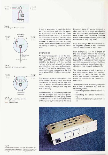
Fig. 13<br />
Remote power feeding unit with instruments for<br />
output voltage and current. <strong>The</strong> press buttons on<br />
the right are used when locating a cable break<br />
A fault in a repeater is located with the<br />
aid <strong>of</strong> an oscillator built into the repeater.<br />
Each oscillator is tuned to a fault<br />
location frequency which is individual<br />
for each repeater station. <strong>The</strong> fault location<br />
frequencies lie in the band 4800-<br />
5000 kHz at intervals <strong>of</strong> 2 kHz , and they<br />
can be measured in the receiving terminal<br />
using an ordinary selective instrument.<br />
Branching<br />
An important requirement for the category<br />
<strong>of</strong> line systems to which ZAX-ZAC<br />
120 T and 480 T belong is that it must be<br />
possible to branch <strong>of</strong>f the wanted<br />
number <strong>of</strong> channels at arbitrary places<br />
along the line, in an easy and economical<br />
way. This facility has already been<br />
exploited in many cases where the first<br />
generation <strong>of</strong> ZAX 120 T has been installed.<br />
<strong>The</strong> frequency plans that apply for the<br />
120 and 480-channel systems, where the<br />
modulation frequency for the high line<br />
band is always accessible on the line,<br />
makes it easy to arrange both stop and<br />
leak branching.<br />
Stop branching in two-wire systems can<br />
only be arranged at a four-wire point,<br />
which means that the line group bands<br />
in both directions are terminated in the<br />
ordinary way by translation to the basic<br />
frequency band. In such a station it is<br />
also possible to arrange equalization<br />
and remote power feeding and it is also<br />
easy to carry out frequency frogging,<br />
which is advantageous as regards noise<br />
in the case <strong>of</strong> very long lines.<br />
Stop branching 5 , which is also utilized<br />
on large line systems, is well known and<br />
will not be discussed in detail here.<br />
Leak branching can be arranged on<br />
two-wire systems without the necessity<br />
<strong>of</strong> terminating the line group band in the<br />
main through path. <strong>The</strong> main advantages<br />
<strong>of</strong> this method are that it requires<br />
very little extra equipment and that local<br />
arrangements and power losses do not<br />
affect the main through-going traffic.<br />
<strong>The</strong> disadvantage <strong>of</strong> leak branching is<br />
that the frequency band that has been<br />
branched <strong>of</strong>f cannot be used for new<br />
traffic after the branching point, which<br />
would be possible in the case <strong>of</strong> stop<br />
branching.<br />
Three types <strong>of</strong> leak branching are possible<br />
in the LM <strong>Ericsson</strong> 120 and 480channel<br />
systems:<br />
— branching for direct termination, fig.<br />
10<br />
— branching for remote termination,<br />
fig. 11<br />
— remotely fed branching terminal, fig.<br />
12.


