

Colour Display System SEMIGRAF 240 - The history of Ericsson
Colour Display System SEMIGRAF 240 - The history of Ericsson
Colour Display System SEMIGRAF 240 - The history of Ericsson

Create successful ePaper yourself
Turn your PDF publications into a flip-book with our unique Google optimized e-Paper software.
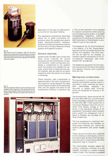
Fig. 16<br />
Housing for one line repeater, right. On the left is<br />
shown a cut-away view <strong>of</strong> a housing for a remotely<br />
fed branching terminal with the multiplex equipment<br />
at the top and the line repeater and DC/DC<br />
converter below<br />
Fig. 17<br />
<strong>The</strong> line repeater shelf for rack mounting accommodates<br />
three repeaters. <strong>The</strong> connection to the<br />
power input adapter and the termination box for<br />
coaxial cable can be seen above the various repeaters<br />
dependent on the type <strong>of</strong> cable and input<br />
points for the power feeding.<br />
<strong>The</strong> application possibilities described<br />
above are <strong>of</strong> great economical importance<br />
when the systems are used in<br />
public telecommunication networks,<br />
and they are <strong>of</strong>ten an essential condition<br />
for their use in military networks, railway<br />
systems and pipeline projects.<br />
Service channels<br />
<strong>System</strong>s ZAX 120-480 T also contain two<br />
extra carrier channels for service<br />
purposes and the transmission <strong>of</strong> special<br />
functions. <strong>The</strong>se connections constitute<br />
a complement to the systems<br />
when the systems are installed for railways,<br />
power lines or pipelines and can,<br />
for example, also be used for an alarm<br />
telephone when the system is run along<br />
a motorway.<br />
<strong>The</strong>se channels, with a bandwidth <strong>of</strong><br />
approximately 4 kHz each, are placed in<br />
the frequency range between the edge<br />
<strong>of</strong> the frequency band <strong>of</strong> the directional<br />
filter and the regular line band for the<br />
transmission direction in question, fig.<br />
4. One <strong>of</strong> the channels is only intended<br />
for speech connections when servicing<br />
and maintaining the system. A portable<br />
loudspeaking telephone containing<br />
equipment for sending and receiving in<br />
both directions <strong>of</strong> transmission is provided<br />
for use on this channel.<br />
<strong>The</strong> telephone, fig. 15, which is fed from<br />
a dry battery, is <strong>of</strong> the "handy-talkie"<br />
type and can be connected direct to the<br />
system line repeaters. <strong>The</strong> other channel<br />
can be used for, for example, an<br />
omnibus speech connection or for voice-frequency<br />
telegraphy, data transmission<br />
etc. as required.<br />
<strong>The</strong> additional equipment for this channel<br />
is permanently housed in the system<br />
line repeater housing, and is powered<br />
from the line.<br />
Mechanical construction<br />
<strong>The</strong> equipment in a terminal or powerfeeding<br />
intermediate repeater station is<br />
mounted in racks, whereas the dependent<br />
intermediate repeaters are<br />
mounted in sealed steel housings,<br />
which are designed for burying in the<br />
ground.<br />
<strong>The</strong> terminal rack, which can be the LM<br />
<strong>Ericsson</strong> M4 or M5 rack, accommodates<br />
three completely separate line systems<br />
for ZAX-ZAC 480 T. Each system has its<br />
own power feeding in the form <strong>of</strong> a converter<br />
from battery voltage to 12 V,<br />
which is the operating voltage <strong>of</strong> the<br />
equipment. Test outlets, alarm indicator<br />
and a switch for changeover from Aalarm<br />
to B-alarm are provided on the<br />
front <strong>of</strong> each unit.<br />
<strong>The</strong> line equipment in a terminal comprises<br />
line matching, line repeater, remote<br />
power feeding unit, central frequency<br />
generation and power supply<br />
unit.<br />
<strong>The</strong>se various functions are combined<br />
to form shelves or shelf stacks, which in<br />
principle makes possible arbitrary placing<br />
in the rack or combination with other<br />
equipment, figs. 6, 13 and 17.<br />
<strong>The</strong> intermediate repeater station for<br />
outdoor installation consists <strong>of</strong> a line<br />
repeater mounted in a sealed housing<br />
made <strong>of</strong> steel. <strong>The</strong> housing is available


