MANUAL DE INSTRUCCIONES INSTRUCTION MANUAL
MANUAL DE INSTRUCCIONES INSTRUCTION MANUAL
MANUAL DE INSTRUCCIONES INSTRUCTION MANUAL

You also want an ePaper? Increase the reach of your titles
YUMPU automatically turns print PDFs into web optimized ePapers that Google loves.
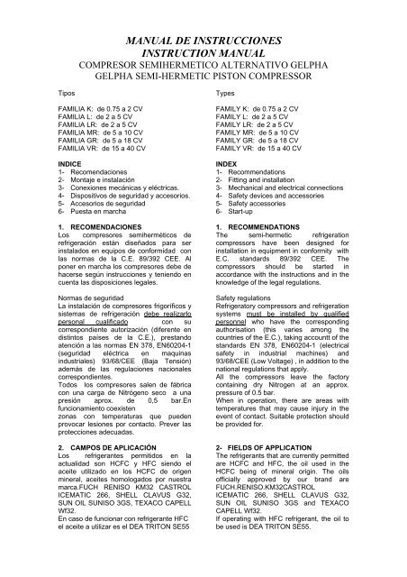
Tipos<br />
<strong>MANUAL</strong> <strong>DE</strong> <strong>INSTRUCCIONES</strong><br />
<strong>INSTRUCTION</strong> <strong>MANUAL</strong><br />
COMPRESOR SEMIHERMETICO ALTERNATIVO GELPHA<br />
GELPHA SEMI-HERMETIC PISTON COMPRESSOR<br />
FAMILIA K: de 0.75 a 2 CV<br />
FAMILIA L: de 2 a 5 CV<br />
FAMILIA LR: de 2 a 5 CV<br />
FAMILIA MR: de 5 a 10 CV<br />
FAMILIA GR: de 5 a 18 CV<br />
FAMILIA VR: de 15 a 40 CV<br />
INDICE<br />
1- Recomendaciones<br />
2- Montaje e instalación<br />
3- Conexiones mecánicas y eléctricas.<br />
4- Dispositivos de seguridad y accesorios.<br />
5- Accesorios de seguridad<br />
6- Puesta en marcha<br />
1. RECOMENDACIONES<br />
Los compresores semiherméticos de<br />
refrigeración están diseñados para ser<br />
instalados en equipos de conformidad con<br />
las normas de la C.E. 89/392 CEE. Al<br />
poner en marcha los compresores debe de<br />
hacerse según instrucciones y teniendo en<br />
cuenta las disposiciones legales.<br />
Normas de seguridad<br />
La instalación de compresores frigoríficos y<br />
sistemas de refrigeración debe realizarlo<br />
personal cualificado con su<br />
correspondiente autorización (diferente en<br />
distintos países de la C.E.), prestando<br />
atención a las normas EN 378, EN60204-1<br />
(seguridad eléctrica en maquinas<br />
industriales) 93/68/CEE (Baja Tensión)<br />
además de las regulaciones nacionales<br />
correspondientes.<br />
Todos los compresores salen de fábrica<br />
con una carga de Nitrógeno seco a una<br />
presión aprox. de 0,5 bar.En<br />
funcionamiento coexisten<br />
zonas con temperaturas que pueden<br />
provocar lesiones por contacto. Prever las<br />
protecciones adecuadas.<br />
2. CAMPOS <strong>DE</strong> APLICACIÓN<br />
Los refrigerantes permitidos en la<br />
actualidad son HCFC y HFC siendo el<br />
aceite utilizado en los HCFC de origen<br />
mineral, aceites homologados por nuestra<br />
marca.FUCH RENISO KM32 CASTROL<br />
ICEMATIC 266, SHELL CLAVUS G32,<br />
SUN OIL SUNISO 3GS, TEXACO CAPELL<br />
Wf32.<br />
En caso de funcionar con refrigerante HFC<br />
el aceite a utilizar es el <strong>DE</strong>A TRITON SE55<br />
Types<br />
FAMILY K: de 0.75 a 2 CV<br />
FAMILY L: de 2 a 5 CV<br />
FAMILY LR: de 2 a 5 CV<br />
FAMILY MR: de 5 a 10 CV<br />
FAMILY GR: de 5 a 18 CV<br />
FAMILY VR: de 15 a 40 CV<br />
IN<strong>DE</strong>X<br />
1- Recommendations<br />
2- Fitting and installation<br />
3- Mechanical and electrical connections<br />
4- Safety devices and accessories<br />
5- Safety accessories<br />
6- Start-up<br />
1. RECOMMENDATIONS<br />
The semi-hermetic refrigeration<br />
compressors have been designed for<br />
installation in equipment in conformity with<br />
E.C. standards 89/392 CEE. The<br />
compressors should be started in<br />
accordance with the instructions and in the<br />
knowledge of the legal regulations.<br />
Safety regulations<br />
Refrigeratory compressors and refrigeration<br />
systems must be installed by qualified<br />
personnel who have the corresponding<br />
authorisation (this varies among the<br />
countries of the E.C.), taking accountt of the<br />
standards EN 378, EN60204-1 (electrical<br />
safety in industrial machines) and<br />
93/68/CEE (Low Voltage) , in addition to the<br />
national regulations that apply.<br />
All the compressors leave the factory<br />
containing dry Nitrogen at an approx.<br />
pressure of 0.5 bar.<br />
When in operation, there are areas with<br />
temperatures that may cause injury in the<br />
event of contact. Suitable protection should<br />
be provided for.<br />
2- FIELDS OF APPLICATION<br />
The refrigerants that are currently permitted<br />
are HCFC and HFC, the oil used in the<br />
HCFC being of mineral origin. The oils<br />
officially approved by our brand are<br />
FUCH.RENISO.KM32CASTROL<br />
ICEMATIC 266, SHELL CLAVUS G32,<br />
SUN OIL SUNISO 3GS and TEXACO<br />
CAPELL Wf32.<br />
If operating with HFC refrigerant, the oil to<br />
be used is <strong>DE</strong>A TRITON SE55.
3- MONTAJE E INSTALACIÓN<br />
Los compresores deben colocarse de forma<br />
horizontal y a ser posible en lugares<br />
ventilados; si esto no es posible deben<br />
tomarse las medidas oportunas para evitar<br />
que la maquina sufra un sobre calentamiento<br />
y origine daños irreparables en la misma.<br />
Los compresores Gelpha deben montarse<br />
normalmente sobre los muelles suministrados<br />
por fábrica para evitar la transmisión de<br />
vibraciones.<br />
En caso de montarse de forma rígida,<br />
asegurarse de que no se produzcan ruidos o<br />
roturas.<br />
En el momento de envío del compresor o<br />
unidad, los compresores están bloqueados<br />
sobre escuadras (3) de hierro para evitar<br />
daños en el transporte. Fig.1<br />
FIG 1<br />
En caso de traslado la maquina debe fijarse<br />
apretando la tuerca (1) hasta que la placa (2)<br />
haga que la escuadra (3) quede aprisionada.<br />
En el momento de la instalación debe<br />
aflojarse la tuerca (1) hasta dejar la maquina<br />
completamente flotando. Fig.1<br />
3- MOUNTING AND INSTALLATION<br />
The compressors must be placed horizontally<br />
and, if possible, in well-aired places. If this is<br />
not possible, suitable measure must be taken<br />
to prevent the machine from overheating and<br />
being damaged irreparably.<br />
Gelpha compressors must normally be<br />
mounted on the springs supplied by the<br />
factory to prevent any transmission of<br />
vibration.<br />
If mounted in a rigid manner, make sure no<br />
noise or breakage is caused. When shipping<br />
the compressor or unit, the compressors<br />
must be blocked on iron squares (3) to avoid<br />
damage in transport. Fig 1.<br />
FIG 1<br />
When moving the machine, it must be fixed by<br />
tightening nut (1) until the plate (2) traps the<br />
square (3). When installing, the nut (1) must<br />
be loosened to leave the machine floating<br />
freely. Fig.1<br />
TABLA <strong>DE</strong> COMPRESORES SEGÚN COLOR <strong>DE</strong>L MUELLE<br />
TABLE OF COMPRESSORS ACCORDING TO THE SPRING COLOUR<br />
LADO MOTOR / MOTOR SI<strong>DE</strong> LADO CARTER / HOUSING SI<strong>DE</strong><br />
07K 3.2 ROJO / RED ROJO / RED<br />
07K 5.2 ROJO / RED ROJO / RED<br />
1K 5.2 ROJO / RED ROJO / RED<br />
1K7.2 ROJO / RED ROJO / RED<br />
1,5K7.2 ROJO / RED ROJO / RED<br />
1,5K8.2 ROJO / RED ROJO / RED<br />
1.5K9.2 ROJO / RED ROJO / RED<br />
2K8.2 ROJO / RED ROJO / RED<br />
2K9.2 ROJO / RED ROJO / RED<br />
2L9.2 AZUL CLARO / LIGHT BLUE MARRON / BROWN<br />
2L13.2 AZUL CLARO / LIGHT BLUE MARRON / BROWN<br />
3L13.2 MARRON / BROWN MARRON / BROWN<br />
3L17.2 MARRON / BROWN MARRON / BROWN<br />
3L19.2 MARRON / BROWN MARRON / BROWN<br />
4L17.2 MARRON / BROWN MARRON / BROWN<br />
4L19.2 MARRON / BROWN MARRON / BROWN<br />
4L23.2 MARRON / BROWN MARRON / BROWN<br />
5L23.2 MARRON / BROWN MARRON / BROWN<br />
3LR17.2 MARRON / BROWN MARRON / BROWN<br />
4LR17.2 MARRON / BROWN MARRON / BROWN<br />
4LR23.2 MARRON / BROWN MARRON / BROWN<br />
5LR23.2 MARRON / BROWN MARRON / BROWN<br />
6MR27.2 VER<strong>DE</strong> / GREEN ROJO / RED<br />
7MR27.2 VER<strong>DE</strong> / GREEN ROJO / RED<br />
7MR32.2 VER<strong>DE</strong> / GREEN ROJO / RED<br />
9MR32.2 VER<strong>DE</strong> / GREEN ROJO / RED<br />
6GR31.3 VER<strong>DE</strong> / GREEN ROJO / RED<br />
8GR31.3 VER<strong>DE</strong> / GREEN ROJO / RED<br />
8GR39.3 VER<strong>DE</strong> / GREEN ROJO / RED<br />
10GR39.3 ROJO / RED ROJO / RED<br />
10GR50.3 ROJO / RED ROJO / RED<br />
15GR50.3 NEGRO / BLACK NEGRO / BLACK<br />
12GR60.3 NEGRO / BLACK NEGRO / BLACK<br />
18GR60.3 NEGRO / BLACK NEGRO / BLACK<br />
15VR73.4 /25VR73.4 NEGRO / BLACK NEGRO / BLACK<br />
20VR83.4 /30VR83.4 NEGRO / BLACK NEGRO / BLACK<br />
22VR93.4 /33VR93.4 NEGRO / BLACK NEGRO / BLACK<br />
30VR118.4 /40VR118.4 NEGRO / BLACK NEGRO / BLACK
4.TUBOS <strong>DE</strong> CONEXIÓN<br />
El compresor se entrega bajo presión de<br />
Nitrógeno y es recomendable mantenerla<br />
justo hasta el inicio del proceso de vacío.<br />
En el momento de conectar los tubos<br />
deben estar los grifos de la maquina en<br />
posición de cerrado. Las conexiones están<br />
preparadas para poder utilizar tubos<br />
estándar según los distintos modelos de<br />
compresor.<br />
Los tubos a utilizar deben estar<br />
completamente limpios y el interior de los<br />
mismos secos (libre de virutas, oxido o<br />
recubrimientos de fosfato).<br />
Conexión presión Alta<br />
High pressure connection<br />
Conexión presión Baja<br />
Low pressure connection<br />
Vaciado de aceite<br />
Oil emptying<br />
Conexión P.D.A.<br />
P.D.A. Connection<br />
Filtro aceite<br />
Oil filter<br />
Kit inyección<br />
Injection Kit<br />
Carga aceite<br />
Oil charge<br />
Sonda temperatura<br />
Temperature probe<br />
Retorno Sep.Aceite<br />
Oil Sep. Return<br />
LA línea aspiración<br />
LA suction line<br />
LA1 conex. Manómetro<br />
LA1 Press. Gauge connection<br />
LD línea descarga<br />
Discharge line<br />
LD1 conex. Manómetro<br />
LD1 Press. Gauge connection<br />
4. CONNECTION PIPES<br />
The compressor is delivered under<br />
pressure with Nitrogen and it is best to<br />
maintain this pressure until just before the<br />
beginning of the emptying process.<br />
When connecting the pipes, the taps of the<br />
machine must be closed. The connections<br />
are prepared for the use of standard pipes,<br />
depending on the various compressor<br />
models.<br />
The pipes to be used must be completely<br />
clean and dry inside (free from chips, rust<br />
or phosphate linings)<br />
K-L LR-MR-GR-VR<br />
1/8” NPT 1/8” NPT<br />
1/8” NPT 1/8” NPT<br />
1/8” NPT 1/8” NPT<br />
- ¼” NPT<br />
- 2 x M8<br />
- -<br />
1/8” NPT ¼” NPT<br />
- -<br />
1/8” NPT 1/8” NPT<br />
- -<br />
OD ¼” (7/16 SAE) OD ¼” (7/16 SAE)<br />
- -<br />
OD ¼” (7/16 SAE) OD ¼” (7/16 SAE)<br />
MO<strong>DE</strong>LO / MO<strong>DE</strong>L LA Línea Aspiración LD LíneaDescarga<br />
LA Suction Line LD Discharge line<br />
07K3.2 / 07K5.2<br />
1/2 3/8<br />
1K5.2 / 1K7.2/ 1.5K7.2 / 1.5K8.2<br />
1.5K9.2 / 2K8.2/ 2K9.2<br />
5/8 1/2<br />
2L9.2 / 2L13.2 7/8 1/2<br />
3L13.2/ 4L17.2 7/8 5/8<br />
3L19.2 / 4L23.2/ 5L23.2 1”1/8 5/8<br />
3LR13.2 / 4LR17.2/ 5LR23.2<br />
1”1/8 5/8<br />
6MR27.2 / 6GR31.3 1”3/8 7/8<br />
7MR27.2 / 8GR31.3/ 8GR39.3<br />
1”3/8 1”1/8<br />
9MR32.2 / 10GR39.3 /10GR50.3 / 12GR60.3<br />
15GR50.3 / 18GR60.3 1”5/8 1”1/8<br />
15VR73.4<br />
1”5/8 1”1/8<br />
25VR73.4/ 20VR83.4 / 30VR83.4 2”1/8 1”1/8<br />
22VR93.4/ 33VR93.4 2”5/8 1”3/8
4.1- CONEXIONES ELECTRICAS<br />
Los compresores y accesorios eléctricos<br />
cumplen las normas 93/68/CEE de baja<br />
tensión.<br />
La instalación eléctrica de las maquinas<br />
debe hacerla personal autorizado<br />
siguiendo las normas de seguridad<br />
EN/60204/60355 en los países de la CE.<br />
Teniendo en cuenta además las normas<br />
nacionales vigentes.<br />
Norma de seguridad<br />
Las dimensiones de los contactos, cables y<br />
fusibles deben calcularse en base al<br />
régimen máximo que pueda trabajar el<br />
compresor. (Véase placa de datos del<br />
compresor)<br />
ATENCIÓN<br />
Antes de poner en marcha el compresor,<br />
hay que asegurarse de que la tensión de la<br />
red corresponda a la indicada en la placa<br />
del compresor.<br />
La conexión del motor debe hacerse de<br />
acuerdo con el esquema anexo.<br />
Una mala conexión implica el riesgo de<br />
deteriorar el motor.<br />
5 DISPOSITIVO <strong>DE</strong> SEGURIDAD<br />
Todos los motores incorporan en su<br />
bobinado una cadena de termostatos (uno<br />
por fase) que mediante la serie de control<br />
paran el compresor en caso de<br />
sobrecalentamiento del motor.<br />
Los compresores que incorporen bomba de<br />
aceite deben llevar un Presostato<br />
diferencial según esquema, que protegerá<br />
la maquina en caso de quedarse sin<br />
presión de aceite.<br />
Son necesarios para un correcto ajuste de<br />
la instalación los controles de presión (Alta<br />
y Baja) que limiten los regímenes de<br />
aplicación.<br />
6- ACCESORIOS <strong>DE</strong> SEGURIDAD<br />
Resistencia de cárter<br />
En períodos de inactividad impide la<br />
concentración de refrigerante en el aceite.<br />
Kit de inyección<br />
Sirve para mantener los limites de<br />
aplicación térmica si trabajamos con R22<br />
en baja temperatura.<br />
Su conexión se hace según indicaciones<br />
mecánicas y eléctricas indicadas en los<br />
esquemas.<br />
4.1. ELECTRICAL CONNECTIONS<br />
The compressors and electrical accessories<br />
comply with standards 93/68/CEE on low<br />
voltage.<br />
The electrical installation of the machines<br />
must be undertaken by authorised persons<br />
in accordance with safety standards<br />
EN/60204/60355 in countries of the E.U.,<br />
bearing in mind too all national standards in<br />
force.<br />
Safety Standard<br />
The sizes of the contacts, cables and fuses<br />
must be calculated on the basis of the<br />
maximum possible working rate of the<br />
compressor. (See compressor data plate).<br />
WARNING<br />
Before starting the compressor, we must<br />
make sure that the mains voltage<br />
corresponds to that indicated on the<br />
compressor plate.<br />
The motor connection must be carried out<br />
in accordance with the attached diagram.<br />
Poor connections may cause motor wear.<br />
5. SAFETY <strong>DE</strong>VICE<br />
The coiling of all motors includes a line of<br />
thermostats (one in each phase) which, by<br />
means of the control series, stop the<br />
compressor in the event of motor<br />
overheating.<br />
The compressor incorporating an oil pump<br />
must carry a differential Pressure gauge<br />
according to the diagram, which will protect<br />
the machine in the event of it losing oil<br />
pressure.<br />
For correct adjustment of the installation,<br />
the pressure (High and Low) controls<br />
restricting the application rates are needed.<br />
6. SAFETY ACCESSORIES<br />
Housing resistance<br />
In periods of inactivity, this prevents coolant<br />
from concentrating in the oil.<br />
Injection kit<br />
This serves to maintain the limits of thermal<br />
application if we are working with the R22<br />
at low temperatures.<br />
It is connected in accordance with the<br />
mechanical and electrical indications of the<br />
diagrams.
Como accesorio del kit se suministra una<br />
sonda termostática colocada en la culata,<br />
que controla el sistema en caso de<br />
sobrepasar los regímenes térmicos<br />
recomendados.<br />
Presostato diferencial de aceite<br />
En los compresores que incorporen bomba<br />
de aceite ( Modelos GLR, GMR y G9R) es<br />
necesario utilizar un presostato que<br />
interrumpa el funcionamiento de la maquina<br />
en el supuesto de falta de presión de aceite<br />
en la bomba.<br />
Su conexión eléctrica esta indicada en el<br />
esquema que se adjunta a continuación.<br />
As an accessory of the kit, a thermostatic<br />
probe is supplied, fitted to the head, which<br />
controls the system if the recommended<br />
thermal rates are exceeded.<br />
Oil differential pressure gauge<br />
The compressors including an oil pump<br />
(GLR, GMR and G9R Models) must have a<br />
pressure gauge to stop the machine from<br />
working in the event of a lack of pressure in<br />
the oil pump.<br />
The electrical connection of the gauge is<br />
indicated in the diagram attached below.<br />
ESQUEMAS ELECTRICOS / ELECTRICAL DIAGRAMS
7- PUESTA EN MARCHA<br />
Una vez verificada la instalación de<br />
posibles fugas (utilícese nitrógeno seco)<br />
debe vaciarse la instalación incluyendo el<br />
compresor (lleva también carga de<br />
nitrógeno seco) con bomba de vacío<br />
conectada a un tubo en presión de alta y el<br />
otro en baja, hasta alcanzar completamente<br />
el vacío.<br />
Debemos recordar que para hacer el vacío<br />
deben de estar las válvulas solenoides en<br />
posición de abiertas.<br />
NUNCA debe ponerse en marcha el<br />
compresor en vacío ni para probarlo.<br />
En caso de probar la instalación con aire<br />
seco, recuérdese que las válvulas de<br />
servicio del compresor deben de estar<br />
cerradas para evitar que se altere la<br />
estabilidad del aceite.<br />
7.1- Carga de refrigerante<br />
Para cargar de refrigerante, debe<br />
comprobarse que el nivel de aceite es el<br />
correcto y a continuación póngase en<br />
marcha la resistencia del cárter.<br />
El refrigerante puede ser cargado en forma<br />
líquida directamente al condensador o<br />
recipiente de la unidad, con el compresor<br />
parado aprovechando por ejemplo el vacío<br />
previo a la puesta en marcha. Si después<br />
de la puesta en marcha hace falta<br />
completar la carga, puede hacerse en fase<br />
gaseosa por aspiración (o forzosamente<br />
con líquido para los refrigerantes<br />
zeotrópicos) dosificando el caudal a fin de<br />
evitar un exceso de líquido que pueda<br />
comprometer las válvulas de aspiración o la<br />
propia carga de aceite<br />
7.2- Comprobaciones<br />
- El nivel de aceite debe estar según se<br />
muestra en la fig.5<br />
Cuando un compresor sea desmontado de<br />
la instalación para su sustitución, al montar<br />
el nuevo se debería comprobar si es<br />
necesario drenar parte del aceite inicial<br />
existente en el sistema.<br />
- La temperatura del compresor esta en su<br />
óptimo funcionamiento ( de 15ºC a 20ºC<br />
más que la temperatura ambiente)<br />
-Comprobar la funcionalidad de los<br />
dispositivos de seguridad<br />
- Reles de tiempo<br />
- Presostatos de alta y baja<br />
7. STARTING<br />
Once the installation has been checked for<br />
possible leaks (use dry nitrogen), the<br />
installation must be drained, including the<br />
compressor (this also is loaded with dry<br />
nitrogen) with the vacuum pump connected<br />
to a high and low pressure pipe, until the<br />
vacuum is completely formed.<br />
Remember that to make the vacuum, the<br />
solenoid valves must be open.<br />
NEVER start the compressor empty, even<br />
for testing purposes.<br />
If testing the installation with dry air,<br />
remember that the service valves of the<br />
compressor must be closed in order to<br />
avoid any change in the stability of the oil.<br />
7.1. Coolant loading<br />
To change the refrigerant, it must be made<br />
sure that the oil level is correct and then<br />
start the resistance of the housing.<br />
The refrigerant may be changed in liquid<br />
form directly into the condenser or recipient<br />
of the unit, with the compressor turned off,<br />
making use, for instance, of the vacuum<br />
available before starting. If after starting,<br />
the load has to be completed, it may be<br />
undertaken in gaseous phase by suction (or<br />
forcefully with liquids with zeotropic<br />
refrigerants), controlling the flow to make<br />
sure that no surplus liquid enters, which<br />
could damage the suction valves or the oil<br />
load itself.<br />
7.2. Checking<br />
- The oil level must be as we see in Fig. 5.<br />
When a compressor is disassembled from<br />
the installation for replacement, on fitting<br />
the new one we must check whether it is<br />
necessary to drain off part of the oil, there<br />
already being oil in the system.<br />
- The temperature of the compressor is at<br />
optimal working (from 15ºC to 20ºC above<br />
room temperature).<br />
- Check the working of the safety devices<br />
- Time relays<br />
- High and low pressure gauges.
FIG.5<br />
Comprobación nivel de aceite<br />
- El nivel de aceite deberá estar en la<br />
posición que se indica en la (Fig.5) y<br />
se deberá vigilar durante las primeras<br />
horas de funcionamiento para<br />
comprobar si se mantiene cuando se<br />
alcanza el régimen.<br />
- En el supuesto de los compresores<br />
con bomba, puede comprobarse la<br />
presión mediante un manómetro<br />
conectado a la misma, debiendo<br />
marcar 3,5 bar por encima de la<br />
presión de baja.<br />
- Control automático del interruptor de<br />
seguridad del presostato diferencial de<br />
aceite: (Este aparato para la maquina<br />
en caso de que la presión sea inferior a<br />
0,7 bar durante un período de 90<br />
segundos)<br />
CUIDADO!<br />
Si es necesario añadir grandes cantidades<br />
de aceite, existe el riesgo de golpes de<br />
líquido. (Contrólese el retorno de aceite)<br />
7.3- Comprobación de Funcionamiento e<br />
de evaporación<br />
- Temperatura de aspiración<br />
- Temperatura de condensación<br />
- Temperatura de descarga<br />
7.4- Vibraciones<br />
Compruébese que la maquina esta flotando<br />
sobre los muelles y que no se originan<br />
vibraciones extremas en los tubos de<br />
descarga y demás. (Si hay vibraciones, es<br />
posible que se produzca rotura por fatiga<br />
en los tubos)<br />
7.5- Cambio de aceite<br />
Es aconsejable un cambio de aceite en los<br />
primeros días de funcionamiento (120<br />
horas de trabajo) y no será necesario un<br />
nuevo cambio hasta transcurridas 15.000<br />
horas de trabajo.<br />
En caso de que la instalación funcione con<br />
aceite éster, por ser muy detergente e<br />
higroscópico, es aconsejable que se<br />
adopten muchas precauciones en su<br />
manipulación y que se cambie el aceite una<br />
vez al año.<br />
Checking the oil level<br />
- The oil level must be as (Fig. 5.) and<br />
we must watch the first few hours of<br />
working to make sure that it remains<br />
constant.<br />
- In the case of compressors with a<br />
pump, the pressure may be checked by<br />
means of a pressure gauge, and should<br />
mark 3.5 bar above the low pressure.<br />
- Automatic control of the security switch<br />
of the differential oil pressure gauge:<br />
(this apparatus stops the machine if the<br />
pressure falls below 0.7 bar for a period<br />
of 90 seconds).<br />
WARNING!<br />
If larger quantities of oil have to be added a<br />
danger of slugging exists; consequently the<br />
oil return must be checked.<br />
7.3. Checking Working and Installation<br />
- Evaporation temperature<br />
- Suction temperature<br />
- Condensation temperature<br />
- Discharge temperature<br />
7.4. Vibrations<br />
Make sure that the machine is floating on<br />
the springs and that extreme vibrations are<br />
not caused in the unloading pipes and<br />
others (if there are vibrations, the pipes<br />
might break due to fatigue).<br />
7.5. Oil change<br />
It is best to change the oil after the first few<br />
days working (120 hours working) and a<br />
further change will not be necessary until<br />
after 15,000 hours of work.<br />
Should the installation work with ester oil,<br />
as it is highly detergent and hygroscopic,<br />
we recommend great precaution in<br />
handling, and that the oil be changed once<br />
a year.