RC(U)6 Installation and Maintenance Manual - Marine Refrigeration ...
RC(U)6 Installation and Maintenance Manual - Marine Refrigeration ...
RC(U)6 Installation and Maintenance Manual - Marine Refrigeration ...

Create successful ePaper yourself
Turn your PDF publications into a flip-book with our unique Google optimized e-Paper software.
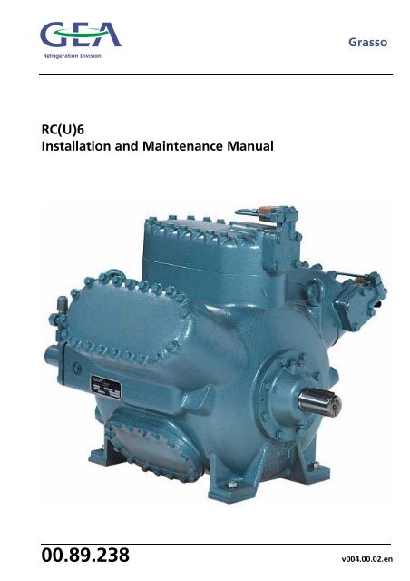
<strong>RC</strong>(U)6<br />
<strong>Installation</strong> <strong>and</strong> <strong>Maintenance</strong> <strong>Manual</strong><br />
00.89.238 v004.00.02.en
<strong>Refrigeration</strong> Division<br />
Grasso<br />
All rights reserved. No part of this publication may be copied or published by means of printing,<br />
photocopying, microfilm or otherwise without prior written consent of Grasso. This restriction<br />
also applies to the corresponding drawings <strong>and</strong> diagrams.<br />
For extra information as to adjustments, maintenance <strong>and</strong> repair, contact the Technical<br />
Departmentof your supplier.<br />
This publication has been written with great care. However, Grasso cannot be held responsible,<br />
neither for any errors occurring in this publication nor for their consequences.<br />
<strong>Installation</strong> <strong>and</strong> <strong>Maintenance</strong> <strong>Manual</strong> <strong>RC</strong>(U)6 v001.99.01.en
<strong>Refrigeration</strong> Division<br />
Grasso<br />
1. Document Information<br />
• This ’lnstallation <strong>and</strong> <strong>Maintenance</strong> manual’ will<br />
be supplied together with the compressor.<br />
• This manual is suitable for both end-user <strong>and</strong><br />
contractor <strong>and</strong> will provide information on how<br />
to transport, install, start-up <strong>and</strong> maintain the<br />
compressor (package). It also contains a number<br />
of "Engineering Data Sheets" <strong>and</strong> the current<br />
"Parts List".<br />
2. Additional Documentation<br />
In addition to the above the following is available<br />
for this series compressor:<br />
• Engineering Data Sheets Book;<br />
This book contains all engineering data for this<br />
series compressor <strong>and</strong> the corresponding<br />
recommended accessories. It is meant to be a<br />
guide to the selection of these components.<br />
• Parts book;<br />
This book contains all current parts of the<br />
compressor <strong>and</strong> accessories together with the<br />
design changes applicable to earlier supplied<br />
components ("History").<br />
• Mounting <strong>and</strong> <strong>Installation</strong> Instructions for<br />
Accessories;<br />
If compressor is supplied with accessories, all the<br />
relevant mounting <strong>and</strong> installation instructions<br />
<strong>and</strong> spare parts information for those<br />
accessories will be supplied together with the<br />
compressor.<br />
PREFACE<br />
v001.99.01.en <strong>Installation</strong> <strong>and</strong> <strong>Maintenance</strong> <strong>Manual</strong> <strong>RC</strong>(U)6 V
<strong>Refrigeration</strong> Division<br />
Grasso<br />
PREFACE<br />
VI <strong>Installation</strong> <strong>and</strong> <strong>Maintenance</strong> <strong>Manual</strong> <strong>RC</strong>(U)6 v001.99.01.en
<strong>Refrigeration</strong> Division<br />
This manual must be carefully read <strong>and</strong><br />
understood prior to installing the<br />
compressor (package)<br />
Installer-oriented information<br />
The compressor (package) is filled with nitrogen to<br />
prevent penetration of moisture. Therefore, keep<br />
the compressor closed until the compressor<br />
(package) is being installed. The compressor is not<br />
filled with oil. How to charge the compressor<br />
package with oil is discussed in Section A, §A2.3,<br />
"Initial oil charge".<br />
After the succesful initial run of the compressor<br />
(package) the warranty chart must be filled in <strong>and</strong><br />
returned to Grasso. A warranty chart is attached<br />
to each compressor.<br />
Safety<br />
This manual is written with great care, but the<br />
contractor/installer is held responsible to examine<br />
this information <strong>and</strong> to care of possible additional<br />
<strong>and</strong>/ or deviated safety measures.<br />
Safety instructions<br />
It is the task of the contractor/installer to inform<br />
<strong>and</strong> explain his client about the operation of the<br />
compressor (Package).<br />
Do respect all federal, state or local safety<br />
regulations/legislations during installing,<br />
connecting <strong>and</strong> operating this compressor<br />
(package).<br />
Typographic signs:<br />
Grasso<br />
Indicates a caution, note or procedure to<br />
which you should pay special attention.<br />
Read it carefully!<br />
Values Between [ ]<br />
Values between [ ] are read-outs of Grasso’s<br />
electronic control device Monitron.<br />
GENERAL SAFETY INSTRUCTIONS<br />
v001.99.01.en <strong>Installation</strong> <strong>and</strong> <strong>Maintenance</strong> <strong>Manual</strong> <strong>RC</strong>(U)6 VII
<strong>Refrigeration</strong> Division<br />
Grasso<br />
GENERAL SAFETY INSTRUCTIONS<br />
VIII <strong>Installation</strong> <strong>and</strong> <strong>Maintenance</strong> <strong>Manual</strong> <strong>RC</strong>(U)6 v001.99.01.en
<strong>Refrigeration</strong> Division<br />
General information<br />
Grasso<br />
Operating limits <strong>and</strong> switch settings<br />
(for values between [ ] brackets refer to the Instruction <strong>Manual</strong> of the Monitron)<br />
Timers Time interval refer to chapter:<br />
Switching frequency max. 6 starts per hour A2.10.1<br />
Time interval between stopping <strong>and</strong> re-starting min. 2 minutes A2.10.2<br />
Time interval between starting <strong>and</strong> re-starting min. 10 minutes A2.10.2<br />
Time interval between unloading <strong>and</strong> loading min. 3 minutes B1.2<br />
Oil system limits Value<br />
Oil level 25 - 75% crankcase sight glass B4<br />
Min. oil temperature warmer than surroundings <strong>and</strong> ≥ 20 °C (68 °F)<br />
for NH3 <strong>and</strong> ≥ 30 °C (86 °F) for halocarbons<br />
A2.8<br />
Max. oil temperature [max. Toil] see oil selection table in the appendix section B1.2<br />
Lubricating oil pressure difference [min dOil] between 1.5 <strong>and</strong> 2.5 bar<br />
Setting approx. 1.8 bar<br />
A2.5.2<br />
Temperature <strong>and</strong> pressure limits Value<br />
GENERAL INFORMATION AND SURVEY<br />
OF SETTINGS AND LIMITS<br />
Max. discharge temperature [max Tdis] 155 °C (311 °F) B1.2<br />
Pdischarge - Psuction < 24.0 bar<br />
Superheat [dTo] ≥ 5 K<br />
Cooling water inlet temperature of cylinder<br />
head cooling system<br />
≥Tcond + 10 K<br />
Pressure safety limits A2.5.2<br />
Subject Feature refer to chapter:<br />
Oil viscosity ≥ 10 cSt during operation at location of bearings<br />
Direction of rotation of compressor drive shaft Counterclockwise when facing shaft end A2.6<br />
v001.99.01.en <strong>Installation</strong> <strong>and</strong> <strong>Maintenance</strong> <strong>Manual</strong> <strong>RC</strong>(U)6 IX
<strong>Refrigeration</strong> Division<br />
Grasso<br />
GENERAL INFORMATION AND SURVEY<br />
OF SETTINGS AND LIMITS<br />
X <strong>Installation</strong> <strong>and</strong> <strong>Maintenance</strong> <strong>Manual</strong> <strong>RC</strong>(U)6 v001.99.01.en
<strong>Refrigeration</strong> Division<br />
Grasso<br />
SUBJECT Page no.:<br />
PREFACE ............................................................................................................................... V<br />
GENERAL SAFETY INSTRUCTIONS ................................................................................................. VII<br />
GENERAL INFORMATION AND SURVEY OF SETTINGS AND LIMITS .......................................... IX<br />
SECTION A: INSTALLATION AND PREPARATIONS FOR USE ....................................................... A1.1<br />
A1 INSTALLATION .......................................................................................................................... A1.1<br />
A1.1 Moving instructions <strong>and</strong> storage ................................................................................. A1.1<br />
A1.1.1 Hoisting <strong>and</strong> moving instructions ...................................................................... A1.1<br />
A1.1.2 Storage ............................................................................................................... A1.2<br />
A1.2 Required free space ....................................................................................................... A1.2<br />
A1.3 Foundation requirements .............................................................................................. A1.2<br />
A1.3.1 Concrete structure ............................................................................................. A1.3<br />
A1.3.2 Anchoring ........................................................................................................... A1.4<br />
A1.4 Concrete block mounting instructions .......................................................................... A1.4<br />
A1.4.1 Mounting bare compressor on a concrete block ............................................. A1.4<br />
A1.4.2 Mounting the base frame on a concrete block ................................................ A1.4<br />
A1.5 Connecting to refrigerating system pipework ............................................................. A1.5<br />
A1.6 Connecting the power supply ....................................................................................... A1.6<br />
A1.7 Earthing connections ..................................................................................................... A1.6<br />
A1.8 Separately delivered components.................................................................................. A1.6<br />
A2 PREPARATIONS FOR USE ......................................................................................................... A2.1<br />
A2.1 Leak test of compressor <strong>and</strong> system ............................................................................. A2.1<br />
A2.2 Evacuation/drying the refrigerating system ................................................................. A2.1<br />
A2.3 Initial oil charge .............................................................................................................. A2.1<br />
A2.4 Initial refrigerant charge ................................................................................................ A2.2<br />
A2.5 Adjustment of instruments <strong>and</strong> safety devices ............................................................ A2.2<br />
A2.5.1 Monitron ............................................................................................................. A2.2<br />
A2.5.2 Pressure safety switches ..................................................................................... A2.2<br />
A2.5.3 Re-adjustment of oil pressure regulator ........................................................... A2.3<br />
A2.6 Checking direction of rotation of motor shaft ............................................................. A2.4<br />
A2.7 Installing the (drive) guards .......................................................................................... A2.4<br />
A2.8 Initial oil warm-up .......................................................................................................... A2.4<br />
A2.9 Initial start-up ................................................................................................................. A2.4<br />
A2.9.1 Limitations part load operation <strong>and</strong> start-up.................................................... A2.4<br />
A2.9.2 Pre-start check list .............................................................................................. A2.4<br />
A2.10 Starting <strong>and</strong> stopping procedures ................................................................................ A2.4<br />
A2.10.1 Starting for the very first time ......................................................................... A2.4<br />
A2.10.2 Restart .............................................................................................................. A2.5<br />
A2.10.3 Starting after a seasonal (1 till 6 months) st<strong>and</strong>still or maintenance operations A2.5<br />
A2.10.4 Starting after a long st<strong>and</strong>still periode of time (more than 6 months) ........ A2.5<br />
A2.10.5 Stopping the compressor ................................................................................. A2.5<br />
SECTION B: INSPECTION, MAINTENANCE AND TROUBLE SHOOTING: .Table of contents ....... B.I<br />
SECTION C: APPENDIX : .......Table of contents ...... C.I<br />
SECTION D: STANDARD ILLUSTRATED SPARE PARTS LIST: ....................Table of contents ....... D.I<br />
For oil selection table refer to "Engineering Data"<br />
TABLE OF CONTENTS<br />
v001.99.01.en <strong>Installation</strong> <strong>and</strong> <strong>Maintenance</strong> <strong>Manual</strong> <strong>RC</strong>(U)6 III
<strong>Refrigeration</strong> Division<br />
Grasso<br />
TABLE OF CONTENTS<br />
IV <strong>Installation</strong> <strong>and</strong> <strong>Maintenance</strong> <strong>Manual</strong> <strong>RC</strong>(U)6 v001.99.01.en
<strong>Refrigeration</strong> Division<br />
The compressor is not charged with oil,<br />
therefore, DO NOT start the compressor<br />
before it has been installed <strong>and</strong> prepared<br />
according to the sections A1 <strong>and</strong> A2.<br />
A1 INSTALLATION<br />
Grasso<br />
This section contains instructions for the proper<br />
installation of a Grasso compressor (package).<br />
Before the compressor (package) is ready for the<br />
initial start up, the installation instructions in the<br />
following paragraphs must be followed:<br />
1. The Compressor (Package) should be levelled <strong>and</strong><br />
securely anchored to the foundation (see §A1.4).<br />
2. All piping should be completed as in §A1.5.<br />
3. The system <strong>and</strong> the compressor are to be pressure<br />
tested for leaks (see §A2.1).<br />
4. The system should be evacuated to remove air <strong>and</strong><br />
moisture (see §A2.2).<br />
5. The electric wiring should be completed as per<br />
wiring diagrams. Do not energize the main power<br />
control cabinet until oil is added <strong>and</strong> the direction<br />
of rotation has been checked.<br />
6. The compressor is to be filled with the correct type<br />
<strong>and</strong> amount of lubricating oil (see §A2.3).<br />
7. The drive coupling or V-belt drive system should be<br />
installed.<br />
8. The system should be charged with the correct<br />
amount of refrigerant.<br />
9. The oil should be warmed up above minimum start<br />
up oil temperature (see "Engineering Data").<br />
10. The control cabinet or Monitron CR should be<br />
energized to check the package control<br />
(see §A2.5).<br />
A: INSTALLATION AND PREPARATION FOR USE<br />
A1.1 Moving instructions <strong>and</strong> storage<br />
For loose component or compressor package<br />
weights, refer either to the relevant component<br />
type plate or package lay-out or to the suppliers<br />
document. For bare compressor weights, see<br />
"Engineering Data".<br />
Every precaution must be taken while<br />
moving the package to its final location.<br />
Pushing, pulling or climbing on any<br />
package component or piping, can easily<br />
create damage.<br />
A1.1.1 Hoisting <strong>and</strong> moving instructions<br />
Fig. A1.1 Hoisting a compressor-package<br />
Packaged base frame:<br />
The only places that can be used for safe hoisting<br />
of the package are the four hoisting eyes on the<br />
steel base frame as shown in the above figure.<br />
Prior to hoisting a compressor package with a<br />
V-belt drive arrangement, the factory mounted<br />
drive guard has to be removed. Attach spreader<br />
bars to the slings so as to prevent damage to<br />
piping <strong>and</strong> components.<br />
DO NOT use the component hoisting<br />
eyes to move the package!<br />
These hoisting eyes are intended for<br />
lifting loose components only <strong>and</strong> not for<br />
the entire package!<br />
v001.99.01.en <strong>Installation</strong> <strong>and</strong> <strong>Maintenance</strong> <strong>Manual</strong> <strong>RC</strong>(U)6 A1.1
<strong>Refrigeration</strong> Division<br />
Grasso<br />
Bare compressor or loose components:<br />
Determine the dead weight of the particular<br />
component (see "Engineering<br />
Data"), prior to moving a bare compressor<br />
or loose component. Use the hoisting<br />
eyes only to lift so, DO NOT sling<br />
from other compressor parts (see figure<br />
A1.1A).<br />
Fig. A1.1A Hoisting angle bare shaft compressor<br />
Moving by fork-lift truck<br />
The bare compressor or package can be<br />
transported with a fork-lift truck with the forks<br />
spread as much as possible between the skids. To<br />
simplify moving, the 2 wooden transport beams<br />
must still be mounted underneath the base frame<br />
<strong>and</strong> stored in this way, untill the package is<br />
positioned above its approximate location.<br />
A: INSTALLATION AND PREPARATION FOR USE<br />
A1.1.2 Storage<br />
The compressor (package) is filled with dry<br />
nitrogen. Keep the system closed until the<br />
package is<br />
installed. If the compressor (package) is stored, it<br />
should be kept at all times in a dry location to<br />
prevent corrosion damage. If the compressor<br />
(package) is to be stored for a prolonged period<br />
of time, it should be checked weekly to ensure<br />
that the holding charge of dry nitrogen remains<br />
above atmospheric pressure.<br />
A1.2 Required free space<br />
For easy operating, servicing <strong>and</strong> maintenance<br />
access, the compressor (package) should be at<br />
least installed with sufficient free space around it.<br />
A1.3 Foundation requirements<br />
This paragraph covers measures to be taken for a<br />
compressor (package) on a concrete floor.<br />
Two foundation arrangements are described:<br />
• Compressor package with steel base frame<br />
mounted on a concrete block.<br />
• Bare compressor direct mounted on a concrete<br />
block via grouted machined anchors (see<br />
"Engineering Data"). The mounting surfaces of<br />
these machined anchors must be level without<br />
any deviation <strong>and</strong> projecting at least 10 mm<br />
above the concrete base.<br />
COMPRESSOR AND COMPRESSOR<br />
PACKAGE TO BE MOUNTED ON A<br />
CONCRETE BLOCK<br />
On request, Grasso can calculate the<br />
exact dimensions of the concrete block,<br />
based on the compressor size <strong>and</strong><br />
operating conditions.<br />
A1.2 <strong>Installation</strong> <strong>and</strong> <strong>Maintenance</strong> <strong>Manual</strong> <strong>RC</strong>(U)6 v001.99.01.en
<strong>Refrigeration</strong> Division<br />
A1.3.1 Concrete structure<br />
The concrete block for compressor <strong>and</strong> motor or<br />
compressor package should have a profile as<br />
illustrated in fig. A1.2 <strong>and</strong> made according to the<br />
following recommendations:<br />
Fig. A1.2<br />
Grasso<br />
1 Corkboard<br />
2 Concrete base<br />
3 Basement floor<br />
• The concrete block should be set on firm<br />
footings or on a floor capable of carrying the<br />
weight of the concrete block <strong>and</strong> capable to<br />
absorb the free forces <strong>and</strong> gas forces of the<br />
compressor during operation. The ground under<br />
the concrete block should be horizontal <strong>and</strong> flat<br />
(refer to fig. A1.2).<br />
• The top surface of the block should be level <strong>and</strong><br />
even.<br />
• There should be sufficient free space around the<br />
block to install corkboard (or similar).<br />
• The block should be provided with anchor bolt<br />
recesses or holes (fig A1.3.) according to the<br />
anchor bolt spacing as per package lay out<br />
drawing.<br />
A: INSTALLATION AND PREPARATION FOR USE<br />
A Chemical anchor<br />
B Grouted anchor, grounded to reinforcing steel<br />
Fig. A1.3<br />
It is recommended to consult a concrete specialist/<br />
constructor for the following items:<br />
• The compounding of the concrete with/without<br />
reinforcement.<br />
• The exact grouting depth (dependent on the<br />
soil conditions).<br />
• Installing foundation onto an existing floor, with<br />
sealing corkboard or vibration isolators.<br />
v001.99.01.en <strong>Installation</strong> <strong>and</strong> <strong>Maintenance</strong> <strong>Manual</strong> <strong>RC</strong>(U)6 A1.3
<strong>Refrigeration</strong> Division<br />
A1.3.2 Anchoring<br />
Grasso<br />
After the concrete block has cured the anchors<br />
should be installed as shown in figs. A1.3 <strong>and</strong>/or<br />
A1.4 <strong>and</strong> in case of a package in accordance with<br />
the package lay out drawing. Templates should be<br />
made to locate the anchor bolts or chemical<br />
anchors to match the holes in the bottom flange<br />
of the base frame.<br />
Grout the mortar as given by the supplier<br />
instructions. Install chemical anchors as illustrated<br />
in figure A1.4 <strong>and</strong> according the instructions of<br />
the anchor supplier.<br />
A Drilled chemical anchor (thread size M16)<br />
B Grouted anchor recesses (thread size M16)<br />
Fig. A1.4 Anchoring details<br />
A1.4 Concrete block mounting instructions<br />
A1.4.1 Mounting bare compressor on a concrete<br />
block<br />
If no base frame is applied the compressor <strong>and</strong><br />
motor should be installed as discussed in §A1.3<br />
<strong>and</strong> "Engineering Data".<br />
A: INSTALLATION AND PREPARATION FOR USE<br />
1 Installed chemical anchor before placing the base frame<br />
2 Installing chemical anchor after placing the base frame (base<br />
frame cannot removed easily)<br />
3 Drilling angle<br />
A1.4.2 Mounting the base frame on a concrete<br />
block<br />
General<br />
After the space between base frame <strong>and</strong> concrete<br />
base is filled-up with a filling grout, the package<br />
base frame must be secured tightly to the<br />
foundation block or floor (refer to fig. A1.3).<br />
A1.4 <strong>Installation</strong> <strong>and</strong> <strong>Maintenance</strong> <strong>Manual</strong> <strong>RC</strong>(U)6 v001.99.01.en
<strong>Refrigeration</strong> Division<br />
Grasso<br />
Fig. A1.5 Grouting details<br />
• Levelling the base frame<br />
After the anchor filling mortar is completely cured<br />
the frame should be levelled with a space<br />
between block <strong>and</strong> lower frame flange of 3 - 5<br />
mm. This space largely depends on the sort of<br />
grout or mortar used. Determine this space as<br />
given in the instructions of the grout or mortar<br />
supplier. This space is necessary for levelling using<br />
the base frame adjusting bolts with metal washers<br />
(supplied separately). The base frame should be<br />
levelled on each frame side. Adjust the frame on<br />
each adjusting place until all frame sides are<br />
horizontal.<br />
• Finishing with a self-levelling grout (See figure A1.5)<br />
After levelling is completed the adjusting bolt<br />
ends must be greased to avoid bonding to the<br />
self-levelling grout. The space between concrete<br />
block <strong>and</strong> frame must be completely filled with<br />
the self-levelling grout to ensure that the<br />
complete bottom surface of the base frame will<br />
A: INSTALLATION AND PREPARATION FOR USE<br />
1 Self-levelling grout<br />
2 Adjusting bolt (4x)<br />
3 Washer<br />
4 Temporary barrier strip around <strong>and</strong> inside frame<br />
5 Complete cured concrete block<br />
6 Grout layer<br />
be supported. Therefore, it is not allowed to use<br />
shims between concrete base <strong>and</strong> base frame.<br />
Grouting must be carried out in accordance with<br />
the instructions provided by the grouting supplier.<br />
After complete de-aeration of the grouted layer,<br />
secure the base frame by tightening the anchor<br />
bolt nuts <strong>and</strong> remove all adjusting bolts. At this<br />
stage the drive system can be installed. These<br />
(accessories) installation instructions can be found<br />
in the order manual.<br />
A1.5 Connecting to refrigerating system pipework<br />
After the compressor (package) has been levelled<br />
<strong>and</strong> secured to the foundation, the system piping<br />
may be connected. The suction line(s) <strong>and</strong><br />
discharge line(s) should be installed <strong>and</strong> supported<br />
such that there is no load exerted on the<br />
compressor. The size <strong>and</strong> location of the suction<br />
<strong>and</strong> discharge connections, can be found in the<br />
"Engineering Data" (bare compressor) <strong>and</strong> in case<br />
of a package, the package lay out drawing.<br />
v001.99.01.en <strong>Installation</strong> <strong>and</strong> <strong>Maintenance</strong> <strong>Manual</strong> <strong>RC</strong>(U)6 A1.5
<strong>Refrigeration</strong> Division<br />
Grasso<br />
If an oil rectifier system is applied in the refrigeration<br />
system, the oil return line<br />
must be connected to the oil return connection.<br />
Never connect the oil rectifier return line to<br />
the suction line or to the suction gas filter.<br />
DO NOT ground through the compressor<br />
when arc welding<br />
Suspension of system pipework<br />
To eliminate vibration transmission to the system<br />
piping, the following is recommended:<br />
• Install all piping free of tension.<br />
• Secure the piping by clips or suspenders in two<br />
directions.<br />
• Install (stop) valves, piping <strong>and</strong> accessories such,<br />
that there is no load exerted on the compressor.<br />
A1.6 Connecting the power supply<br />
Before leaving the factory the compressor<br />
package is completely wired*. The connection to<br />
be made by the installer is between main power<br />
source <strong>and</strong> the Monitron CR (if ordered).<br />
Information about further electrical connections<br />
to be made (e.g. crankcase heater, drive motor<br />
starting equipment, thermal protection of drive<br />
motor, automatic start/ stop, motor current<br />
transducer <strong>and</strong> other external electrical devices)<br />
can be found in the order manual.<br />
* If the st<strong>and</strong>ard recommended Monitron CR is applied.<br />
A: INSTALLATION AND PREPARATION FOR USE<br />
A1.7 Earthing connections<br />
Grasso compressors <strong>and</strong> packages are equipped<br />
with litz-wires <strong>and</strong> earth connecting points.<br />
To avoid leakage current flowing through the<br />
components, disconnect all litz-wires when arcwelding.<br />
After all installation functions are<br />
completed, reconnect the litz-wires <strong>and</strong> ground<br />
the package to earth.<br />
A1.8 Separately delivered components<br />
Mount the separately delivered set-components<br />
e.g. oil charge <strong>and</strong> drain valve, according to the<br />
instruction enclosed in each individual set.<br />
A1.6 <strong>Installation</strong> <strong>and</strong> <strong>Maintenance</strong> <strong>Manual</strong> <strong>RC</strong>(U)6 v001.99.01.en
<strong>Refrigeration</strong> Division<br />
Grasso<br />
A2 PREPARATIONS FOR USE<br />
After the Compressor (Package) has been installed<br />
(excl. final connection of drive device), the<br />
following actions should be followed in the order<br />
given:<br />
A2.1 Leak test of compressor <strong>and</strong> system<br />
The compressor (package) has been pressure<br />
tested prior to leaving the factory. In case an<br />
additional leak test is required, this test is should<br />
be carried out with dry nitrogen under pressure<br />
up to a max. of 10 bar(a).<br />
Do NOT add oil to the compressor prior<br />
to pressure testing.<br />
A system leak test should be carried out over 24<br />
hours to ensure that the system is tightly sealed.<br />
Record during the pressure test, the pressure,<br />
ambient temperature <strong>and</strong> outside temperature.<br />
During the initial 6 hours a pressure drop of 2% is<br />
permissable. With respect to temperature<br />
variations, no further pressure loss should be<br />
detected in the remaining 18 hours.<br />
If the test pressure has not decreased by more<br />
than 5% the system can be considered leak free.<br />
A2.2 Evacuation/drying the refrigerating system<br />
For evacuation of compressor only, refer to §B5.<br />
Procedure to evacuate <strong>and</strong> to dry a system:<br />
a) STATUS: System is filled with nitrogen (refer to<br />
§A2.1) <strong>and</strong> no oil into the system (oil prevents any<br />
trapped moisture from boiling off).<br />
b) Verify that all valves in that part of the system to be<br />
evacuated are opened (refer also to the plant<br />
manual).<br />
c) Connect vacuum pump to the evacuation/purging<br />
valve(s) of the compressor (for location of these<br />
valves refer to the "Engineering Data" or to a<br />
connection as mentioned in the plant manual <strong>and</strong><br />
evacuate the system to approx.<br />
5 mm Hg (=6.6 mBar).<br />
A: INSTALLATION AND PREPARATIONS FOR USE<br />
d) Break vacuum by charging dry nitrogen into the<br />
system.<br />
e) Repeat step ’c’.<br />
f) Wait approx. 24 hours.<br />
g) If pressure has been increased (system still contains<br />
moisture), repeat steps ’d’, ’e’ <strong>and</strong> ’f’, otherwise,<br />
continue with the "Initial oil charge" procedure<br />
§A2.3.<br />
A2.3 Initial oil charge<br />
Used or filtered oil should NEVER BE<br />
added to a compressor under any<br />
circumstance.<br />
Use only new oil to be selected from the<br />
oil table (see "Engineering Data").<br />
a) STATUS: System is dried <strong>and</strong> still evacuated (refer to<br />
§A2.2).<br />
b) Close suction <strong>and</strong> discharge stop valves of<br />
compressor <strong>and</strong> oil return line of oil separator<br />
(if present).<br />
c) Fill the compressor crankcase with oil (for oil<br />
quantity see table overleaf) via the oil charge/ drain<br />
valve (for location of this valve refer to the<br />
"Engineering Data").<br />
d) Open evacuation/purging valve(s) of the<br />
compressor (for location of these valves refer to the<br />
"Engineering Data") to bring the compressor to<br />
atmospheric pressure.<br />
e) Fill the following components with oil as given in<br />
the table on the next page with/without prelubrication<br />
valves (explained hereafter) :<br />
- Shaft seal housing via the oil filling opening.<br />
- Oil pump housing via the oil filling opening.<br />
- Oil suction <strong>and</strong> discharge filter housings via the oil<br />
filling openings.<br />
v001.99.01.en <strong>Installation</strong> <strong>and</strong> <strong>Maintenance</strong> <strong>Manual</strong> <strong>RC</strong>(U)6 A2.1
<strong>Refrigeration</strong> Division<br />
A2.4 Initial refrigerant charge<br />
Refrigerant charging should be done in<br />
accordance to the plant manual by qualified<br />
refrigeration engineers.<br />
Oil charging via the suction line of the<br />
compressor is not allowed.<br />
A2.5 Adjustment of instruments <strong>and</strong> safety<br />
devices<br />
A2.5.1 Monitron<br />
Grasso<br />
For adjustments see table overleaf.<br />
A2.5.2 Pressure safety switches<br />
Refer to the table overleaf. Setting procedures are<br />
described in the Safety Switch supplier instructions.<br />
A: INSTALLATION AND PREPARATIONS FOR USE<br />
QUANTITY OF OIL TO BE FILLED (in dm3)<br />
Compressor series <strong>RC</strong>6 Shaft seal housing Oil filters Oil pump Crankcase<br />
<strong>RC</strong>46<br />
11<br />
<strong>RC</strong>66 ± 0.5 ± 1.0 ± 0.5<br />
12<br />
<strong>RC</strong>86 13<br />
A2.2 <strong>Installation</strong> <strong>and</strong> <strong>Maintenance</strong> <strong>Manual</strong> <strong>RC</strong>(U)6 v001.99.01.en
<strong>Refrigeration</strong> Division<br />
Grasso<br />
Settings of compulsory pressure safeties<br />
Read-out<br />
Monitron 1 )<br />
Description Min. value Max. value (pre)-Setting<br />
Psuc Suction pressure 0.3 bar (4.4 psia) NH3 6.2 bar (90 Psia) 5 °C (9 °F) below design<br />
R22 6.8 bar (99 Psia) evaporating temperature<br />
R134a 6.2 bar (90 Psia)<br />
R404A 6.0 bar (87 Psia)<br />
R507 5.8 bar (84 Psia)<br />
Pdis Discharge pressure > Psuc 26.0 bar (377 Psia) 5 °C (9 °F) above design<br />
condensing temperature<br />
Pdis-Psuc > 0 bar 24.0 bar (348 Psia) < 24.0 bar (348 Psia)<br />
dPoil Lubrication oil 1.5 bar (22 Psia) 2.5 bar (36 Psia) The oil pressure<br />
pressure difference<br />
regulator is adjusted at<br />
the works, but it may<br />
occur that this setting<br />
should be corrected<br />
during the initial run<br />
(see A2.5.3)<br />
1 )In case of Monitron the values are measured via pressure transducers, otherwise protection via switches is compulsory.<br />
A2.5.3 Re-adjustment of oil pressure regulator (refer<br />
to fig. A2.1)<br />
Re-adjustment procedure:<br />
a) Run the compressor for 15 minutes until the<br />
crankcase oil is at its stable operating temperature [Toil].<br />
b) Determine the oil pressure difference (difference<br />
between the pressure gauges of the oil <strong>and</strong> suction<br />
or [dOil]).<br />
c) After approx. 15 minutes of operatinf <strong>and</strong> an oil<br />
temperature of 50 °C, the oil pressure difference<br />
should be approx. 2.0-2.5 bar.<br />
During these first minutes the pressure should be<br />
slightly higher.<br />
Fig. A2.1 Oil pressure regulator<br />
A: INSTALLATION AND PREPARATIONS FOR USE<br />
d) Remove the cap nut (3) with alu ring (2), of the oil<br />
pressure regulator if the pressure needs to be<br />
re-adjusted.<br />
e) Turn the slotted pin (1) with a screwdriver clockwise<br />
or counter clockwise for a higher or lower oil<br />
pressure respectively, until the required oil pressure<br />
differences has been achieved.<br />
f) Replace the cap nut (3) with alu ring (2).<br />
1 slotted pin<br />
2 alu ring<br />
3 cap nut<br />
4 return from oil separator<br />
or oil rectifier<br />
5 oil pressure regulator<br />
v001.99.01.en <strong>Installation</strong> <strong>and</strong> <strong>Maintenance</strong> <strong>Manual</strong> <strong>RC</strong>(U)6 A2.3
<strong>Refrigeration</strong> Division<br />
A2.6 Checking direction of rotation of motor shaft<br />
Prior to installing the intermediate coupling element<br />
or V-belts, the direction of rotation of the motor<br />
shaft must be checked either by bumping the<br />
electrical drive motor or by measuring the rotation<br />
of the field (direction of rotation normally counter<br />
clockwise when facing compressor shaft end).<br />
A2.7 Installing the (drive) guards (if present)<br />
Only after the compressor is ready for the initial<br />
startup! Refer to the drive guard installing<br />
procedures included in the order documentation.<br />
A2.8 Initial oil warm up<br />
Prior to the initial start-up (refer to §A2.9), the<br />
crankcase heater (if present) must be energized. For<br />
the min. oil temperature (min. [Toil]) refer to page VII.<br />
A2.9 Initial start-up<br />
Grasso<br />
A2.9.1 Limitations of part load operation <strong>and</strong><br />
start-up<br />
The capacity control serves to adapt the compressor<br />
capacity at any moment as closely as possible to the<br />
refrigerating capacity. In order to adapt the capacity,<br />
a number of cylinders can be put in or out of action<br />
either individually or collectively.<br />
Due to start-up limitations <strong>and</strong> to<br />
limitations of part load operation it may<br />
be that not all available part load steps<br />
are allowed under certain conditions.<br />
Use of incorrect control steps can<br />
damage compressor <strong>and</strong>/or components.<br />
In the case of a Monitron Controller, all these<br />
limitations will be checked automatically.<br />
For a detailed description about these start-up<br />
<strong>and</strong> part load limitations refer to the "Engineering<br />
Data".<br />
A2.9.2 Pre-start check list<br />
The following Paragraph covers only the initial<br />
start of the compressor <strong>and</strong> not the complete<br />
refrigeration plant.<br />
A: INSTALLATION AND PREPARATIONS FOR USE<br />
Be sure that all necessary system valves are open<br />
<strong>and</strong> that the refrigeration system is ready for start<br />
up. Use the following check to guarantee that no<br />
items of importance regarding the compressor<br />
(package) have been overlooked.<br />
a) System is charged with refrigerant.<br />
b) Monitron (if present) is properly installed (refer to<br />
the Monitron Instruction <strong>Manual</strong>).<br />
c) Settings of safety limit switches are adjusted properly.<br />
d) Direction of rotation of compressor crankshaft is<br />
correct.<br />
e) Oil level established in sight glass.<br />
f) Stop valves to the pressure gauges are open (if<br />
present).<br />
g) Suction stop valve is closed (in case the evaporating<br />
temperature is much higher than the design<br />
evaporating temperature) <strong>and</strong> the discharge stop<br />
valve is open.<br />
h) Stop valve in the oil return line of the oil separator<br />
(if present) is closed.<br />
When all items a) through h) are verified, the<br />
compressor (package) is ready for the start-up.<br />
A2.10 Starting <strong>and</strong> stopping procedures<br />
When starting the compressor a distinction should<br />
be made between:<br />
A2.10.1 Starting for the very first time (between<br />
brackets [ ] are Monitron units)<br />
a) Notice §A2.9.2 "Pre-start check list", consult also the<br />
plant manual <strong>and</strong> verify the following items:<br />
- Check the oil temperature [Toil] (refer to the<br />
"Engineering Data").<br />
- Check crankcase oil level (refer to §B4.1).<br />
b) Start the compressor <strong>and</strong> check whether the oil<br />
pressure [Poil] increases.<br />
Maximum 6 starts per hour <strong>and</strong> at least 2<br />
minutes between stopping <strong>and</strong> starting<br />
<strong>and</strong> at least 10 minutes between starting<br />
<strong>and</strong> re-starting<br />
A2.4 <strong>Installation</strong> <strong>and</strong> <strong>Maintenance</strong> <strong>Manual</strong> <strong>RC</strong>(U)6 v001.99.01.en
<strong>Refrigeration</strong> Division<br />
Grasso<br />
c) Slowly open suction stop valve <strong>and</strong> watch suction<br />
pressure [Psuc], which may not exceed the max.<br />
value as given for each refrigerant in §A2.5.2.<br />
Refrigerant liquid hammer, will damage<br />
the compressor;<br />
Superheat is always necessary! [dTo]≥5 K<br />
d) More cylinders will be energized.<br />
Watch maximum allowable motor current<br />
[Imot] (refer to motor type plate).<br />
e) Adjust pressure gauge stop valves, in order to avoid<br />
vibration of the pointers (if present).<br />
f) Open the stop valve in the oil return line from the<br />
oil separator (if present).<br />
Retighten the coupling bolts or check or<br />
correct the tension of the V-belts <strong>and</strong><br />
retighten the foundation bolts (with<br />
due respect to the torque settings given<br />
by the supplier of the fasteners!) after<br />
50 hours of operation.<br />
A2.10.2 Restart (not within 2 minutes after a<br />
stop, respectively starting after a short<br />
st<strong>and</strong>still period of time [les than 1<br />
month]). If Monitron Controlled, refer to<br />
the Monitron Instruction manual)<br />
• Proceed to the starting procedure of §A2.10.1<br />
point a), b) <strong>and</strong> d).<br />
A2.10.3 Starting after a seasonal st<strong>and</strong>still (1 till<br />
6 months) or maintenance operations<br />
• Check settings of control <strong>and</strong> safety equipment<br />
(refer to §A2.5).<br />
• Proceed to the complete starting procedure of<br />
§A2.10.1, items a) through f).<br />
A: INSTALLATION AND PREPARATIONS FOR USE<br />
A2.10.4 Starting after a long st<strong>and</strong>still period of<br />
time (more than 6 months)<br />
Consult your supplier. Monitron "st<strong>and</strong>by" status<br />
(ready to operate during this long period of time)<br />
is not allowed! It is recommended to<br />
proceed with the "Initial start-up" procedure of<br />
§A2.10.1.<br />
A2.10.5 Stopping the compressor<br />
The compressor can be stopped at any moment,<br />
however, consult the supplier if further actions are<br />
required.<br />
v001.99.01.en <strong>Installation</strong> <strong>and</strong> <strong>Maintenance</strong> <strong>Manual</strong> <strong>RC</strong>(U)6 A2.5
<strong>Refrigeration</strong> Division<br />
Grasso<br />
A: INSTALLATION AND PREPARATIONS FOR USE<br />
A2.6 <strong>Installation</strong> <strong>and</strong> <strong>Maintenance</strong> <strong>Manual</strong> <strong>RC</strong>(U)6 v001.99.01.en
<strong>Refrigeration</strong> Division<br />
Grasso<br />
TABLE OF CONTENTS<br />
SUBJECT Page no.:<br />
SECTION B: INSPECTION, MAINTENANCE AND TROUBLE SHOOTING ....................................... B1.1<br />
B1 INSPECTION ................................................................................................................................ B1.1<br />
B1.1 Periodical inspection ......................................................................................................... B1.1<br />
B1.2 Survey of periodical inspections ....................................................................................... B1.1<br />
B2 MAINTENANCE .......................................................................................................................... B1.2<br />
B2.1 Post start-up maintenance ............................................................................................... B1.2<br />
B2.2 First maintenance ............................................................................................................. B1.3<br />
B3 STEPS FOR LONGER SHUT-DOWN PERIODS (more than 6 months) ....................................... B1.4<br />
B4 LUBRICATION DATA .................................................................................................................. B1.4<br />
B4.1 Topping up oil with compressor operating .................................................................... B1.4<br />
B5 EVACUATION OF THE COMPRESSOR ....................................................................................... B1.5<br />
B6 DRAINING AND CHANGE OF OIL ............................................................................................. B1.5<br />
B7 CLEANING OF OIL FILTERS ........................................................................................................ B1.5<br />
B8 CLEANING OF SUCTION GAS FILTER(S) .................................................................................... B1.6<br />
B9 DISMANTLING, INSPECTION AND RE-ASSEMBLY OF SUCTION AND DISCHARGE VALVES .. B1.6<br />
B10 COMPRESSOR PURGING ............................................................................................................ B1.7<br />
B11 TROUBLE SHOOTING TABLE ..................................................................................................... B1.7<br />
v001.99.01.en <strong>Installation</strong> <strong>and</strong> <strong>Maintenance</strong> <strong>Manual</strong> <strong>RC</strong>(U)6 B.I
<strong>Refrigeration</strong> Division<br />
Grasso<br />
TABLE OF CONTENTS<br />
B.II <strong>Installation</strong> <strong>and</strong> <strong>Maintenance</strong> <strong>Manual</strong> <strong>RC</strong>(U)6 v001.99.01.en
<strong>Refrigeration</strong> Division<br />
B1 INSPECTION<br />
B1.1 Periodical inspection<br />
These inspections should be made during the normal<br />
shut-down periods as much as possible, so the<br />
compressor is always ready to operate when required. If,<br />
at that time, the number of running hours slightly differs<br />
from the scheduled period below, the inspection should<br />
nevertheless be carried out.<br />
B1.2 Survey of periodical inspections ("check list")<br />
CHECK POINTS 1) FREQUENCY REMARKS<br />
Oil level in crankcase<br />
Colour of the oil<br />
Grasso<br />
Lubricating oil pressure difference<br />
[dOil]<br />
daily<br />
•<br />
•<br />
weekly<br />
monthly<br />
•<br />
B: INSPECTION, MAINTENANCE<br />
AND TROUBLE SHOOTING<br />
In this way it will not be necessary to stop the<br />
compressor at inconvenient times.<br />
The frequency of inspections is dependent on the type<br />
of installation <strong>and</strong> operating conditions. In the case of<br />
automatically controlled plants, the periodical inspection<br />
are particularly important. The table below sums up all<br />
the points on the compressor that have to be inspected<br />
or maintained along with inspection <strong>and</strong> maintenance<br />
frequencies.<br />
Between 25% <strong>and</strong> 75% height of the sight glass. For topping up oil, refer to<br />
§B4.1.<br />
The oil should be transparently clear. A disappearing white colour points to<br />
dissolved refrigerant. Refer to § B2.2 for oil analysis frequency.<br />
The indication of the oil pressure gauge should be 1.5 - 2.5 bar higher than<br />
the value shown by the suction pressure gauge.<br />
Oil temperature max. [Toil] • Refer to the "Engineering Data".<br />
Oil leakage of shaft seal max. • In case of more than 1 cc/hr contact supplier.<br />
Suction pressure [Psuc] • Check against design conditions. Refer to plant manual.<br />
Discharge pressure [Pdis]<br />
•<br />
Refer to plant manual. For the max. allowable discharge pressure refer to the<br />
technical data of compressor.<br />
Suction superheat [dTo]<br />
Intermediate superheat [dTm] •<br />
� 5 K<br />
Discharge temperature max. • 155 °C (311 °F)<br />
Cooling water temperature (if<br />
present) min.<br />
•<br />
Actual condensing temperature + 10 K.<br />
Oil temperature min. [Toil]<br />
•<br />
During compressor st<strong>and</strong>still the lower part of the crankcase must remain<br />
warmer than the surroundings: � 20 °C (NH3) <strong>and</strong>�30 °C (halocarbons).<br />
Condition of V-belts<br />
Check belts for:<br />
1) Wear (fraying, cuts etc.) <strong>and</strong> ensure that they do not touch the groove<br />
•<br />
bottom.<br />
2) Tension. Too low a tension gives rise to excessive flapping or oscillation in<br />
operation. For correct tension consult the instructions given by the V-belt<br />
supplier.<br />
Adjustment <strong>and</strong> operation of<br />
pressure safety switches<br />
•<br />
Refer to §A2.5 <strong>and</strong> to instructions of switch manufacturer.<br />
Capacity control<br />
•<br />
The time lag between the unloading <strong>and</strong> loading of one cylinder or cylinder<br />
group should generally be at least 3 - 5 minutes.<br />
Switching frequency of the compressor<br />
•<br />
The time interval between stopping <strong>and</strong> starting should be at least 2 minutes<br />
<strong>and</strong> between starting <strong>and</strong> restarting 10 minutes (see §A2.10.2).<br />
Number of operating hours<br />
•<br />
Check the number of operating hours in view of any maintenance operations<br />
to be carried out.<br />
Apart from the above check points, the sound produced by the compressor provides an indication or its mechanical condition. If<br />
abnormal sounds are audible, their cause should be traced <strong>and</strong> removed immediately in order to prevent serious breakdowns.<br />
1 ) During the first 50 operating hours the compressor should be checked regularly for all the points mentioned above, at least<br />
twice every 24 hours <strong>and</strong> more frequently in cases where irregularities are found.<br />
v001.99.01.en <strong>Installation</strong> <strong>and</strong> <strong>Maintenance</strong> <strong>Manual</strong> <strong>RC</strong>(U)6 B1.1
<strong>Refrigeration</strong> Division<br />
Grasso<br />
B2 MAINTENANCE (Contractor’s level)<br />
B2.1 Post start-up maintenance<br />
After the compressor has run for the initial 100<br />
operating hours:<br />
a) Drain the oil <strong>and</strong> refill the compressor with the<br />
correct amount of fresh oil.<br />
b) Exchange or clean the oil discharge filter element.<br />
c) Exchange or clean oil suction filter element (pos 24<br />
of fig. 2.1) as given in §B7.<br />
d) Clean suction gas filter.<br />
e) Check the compressor shaft seal for leakage.<br />
If excessive (more than 1 cc/hr) replace the seal.<br />
f) Check drive<br />
f1) Retighten the coupling mounting bolts with the<br />
torque settings as given by the coupling<br />
manufacturer.<br />
f2) Verify <strong>and</strong> if necessary, correct the tension of<br />
the V-belts as given in the V-belt supplier’s<br />
instructions.<br />
g) Verify <strong>and</strong> if necessary, correct the torque settings<br />
of all foundation bolts as given in § 7.2 of the<br />
Compressor Service Instruction <strong>Manual</strong>.<br />
B: INSPECTION, MAINTENANCE<br />
AND TROUBLE SHOOTING<br />
B1.2 <strong>Installation</strong> <strong>and</strong> <strong>Maintenance</strong> <strong>Manual</strong> <strong>RC</strong>(U)6 v001.99.01.en
<strong>Refrigeration</strong> Division<br />
B2.2 First maintenance<br />
The maintenance schedule below indicates after<br />
how many operating hours maintenance<br />
operations have to be carried out. This schedule<br />
can be regarded as a directive, based on the<br />
experience gained with a large number of<br />
compressors.<br />
For most of the maintenance operations the<br />
compressor must be put out of action. In order to<br />
avoid that this should take place at inconvenient<br />
times, the operations should as much as possible<br />
be affected during a st<strong>and</strong>-still period. The<br />
schedule has been drawn up in such a way that<br />
several operations can be carried out<br />
sumultaneously, which results in reduced<br />
maintenance costs.<br />
<strong>Maintenance</strong><br />
Grasso<br />
Number of<br />
operating<br />
hours<br />
Cleaning of oil suction filter <strong>and</strong><br />
renewal of oil discharge filter<br />
(ref. to par. 9.6).<br />
100 1 ) 2500 2 )<br />
MAINTENANCE SCHEDULE<br />
5000<br />
7500 2 )<br />
$ $<br />
10,000 10,100 12,500 2 )<br />
Major inspection to be carried<br />
out by installation engineer<br />
15,000<br />
17,500 2 )<br />
$ $<br />
Cleaning of suction gas strainer<br />
(ref. to par. 9.7). $ $ $ $<br />
Inspection of suction <strong>and</strong> discharge<br />
valves<br />
(ref. to par. 9.8)<br />
Draining <strong>and</strong> change of oil 3)<br />
(ref. to par. 9.5).<br />
$ $<br />
$ $ $ $<br />
B: INSPECTION, MAINTENANCE<br />
AND TROUBLE SHOOTING<br />
20,000 etc.<br />
1 ) time dependent on pollution.<br />
2 ) Only for NH3-compressors<br />
3 ) In the case of a possible rapid pollution of the oil, it should be drained <strong>and</strong> renewed sooner than at the times given<br />
v001.99.01.en <strong>Installation</strong> <strong>and</strong> <strong>Maintenance</strong> <strong>Manual</strong> <strong>RC</strong>(U)6 B1.3<br />
Major inspection to be carried<br />
out by installation engineer
<strong>Refrigeration</strong> Division<br />
Grasso<br />
B3 STEPS FOR LONGER SHUT-DOWN PERIODS<br />
(> 6 months)<br />
To shut down a compressor for long term periods,<br />
proceed as follows:<br />
a) Tightly shut both the suction <strong>and</strong> discharge stop<br />
valves <strong>and</strong> the stop valve of the oil return line (if<br />
present).<br />
b) Disconnect the power source from the compressor<br />
drive motor <strong>and</strong> the electrical control cabinet of the<br />
Monitron CR (if present).<br />
c) Place a moisture absorbing compound (eg a<br />
dessicant such as silica gel) inside the control cabinet.<br />
d) Place warning tags on the electric system <strong>and</strong> all<br />
closed stop valves.<br />
Prior to starting up after a shut down, change the oil<br />
(refer to §B6) <strong>and</strong> clean or exchange the oil filters (refer<br />
to §B7). Determine the starting <strong>and</strong> stopping<br />
procedure from §A2.10 prior to start the compressor.<br />
B4 LUBRICATION DATA<br />
Determine max Toil <strong>and</strong> set this value in the safety<br />
device (Monitron CR, if present).<br />
Change the oil as soon as an oil analysis (refer to<br />
§B2.2 for frequency) indicates contaminated oil.<br />
It is expressly pointed out that it is not<br />
permitted to mix different types of oil. If<br />
another type of oil is used, first remove<br />
all the stale oil in the filters, oil pump,<br />
crankcase, shaft seal, oil separator <strong>and</strong><br />
oil drains of the installation.<br />
B4.1 Topping up oil with compressor operating<br />
Topping up oil is permitted during compressor<br />
operation.<br />
Be sure that this oil is the same as in the plant<br />
(refer to §B4).<br />
B: INSPECTION, MAINTENANCE<br />
AND TROUBLE SHOOTING<br />
Without affecting the operation of the compressor,<br />
the oil may be topped up by means of a separate oil<br />
pump. This pump enables the oil to be forced into the<br />
crankcase via the oil charging valve, against suction<br />
pressure. If this oil pump is not available, oil can be<br />
charged by reducing the crankcase pressure to below<br />
atmospheric pressure.<br />
The procedure is as follows:<br />
a) Connect a hose to the oil charging valve after<br />
removing the cap nut.<br />
b) Fill the hose with oil <strong>and</strong> immerse its loose end in a<br />
reservoir containing sufficient oil.<br />
c) Close the suction stop valve so, that the suction<br />
pressure falls below the atmospheric pressure.<br />
d) Keep the oil charge valve open as long as the oil in<br />
the crankcase has attained the required level again.<br />
Take care that no air is being drawn into the<br />
crankcase.<br />
e) Slowly open the suction stop valve to avoid liquid<br />
hammer which may damage the compressor.<br />
f) Remove the hose <strong>and</strong> replace the cap nut with<br />
gasket onto the oil charging valve.<br />
Fig. B1 Oil level in compressor sight glass<br />
B1.4 <strong>Installation</strong> <strong>and</strong> <strong>Maintenance</strong> <strong>Manual</strong> <strong>RC</strong>(U)6 v001.99.01.en
<strong>Refrigeration</strong> Division<br />
Grasso<br />
B5 EVACUATION OF THE COMPRESSOR<br />
To evacuate the refrigeration system refer to §A2.2.<br />
Procedure to evacuate the compressor:<br />
a) Close the suction stop valve <strong>and</strong> the stop valve in<br />
the oil return line of the oil separator.<br />
b) Check that the discharge stop valve is open.<br />
c) Set suction pressure safety switch to 0.3 bar(a).<br />
d) Start the compressor (manual).<br />
e) Wait until the compressor will be cut out of<br />
operation either by the min. suction pressure safety<br />
switch [min Psuc] or the min. oil differential<br />
pressure safety switch [dOil].<br />
Do not start the compressor again, but close the<br />
discharge stop valve as soon as possible.<br />
Be sure the compressor will not start again!<br />
g) Remove the remainder of the refrigerant, via the<br />
evacuation/purging valve(s) as prescribed by local<br />
safety regulations. For the location of these valves<br />
refer to the "Engineering Data".<br />
h) Reset the suction pressure safety switch [Psuc].<br />
B6 DRAINING AND CHANGE OF OIL<br />
To top up oil see § B4.1.<br />
Oil changing procedure:<br />
a) Evacuate the compressor (refer to §B5).<br />
b) Drain the oil via the oil charging/drain valve.<br />
Remove the cover of one or more service openings<br />
on the compressor side.<br />
c) Clean the inside of the crankcase with a non-fibrous<br />
cloth (do not use cotton waste!).<br />
d) Replace the service cover(s) with a new gasket.<br />
e) Charge crankcase with clean or fresh oil in<br />
accordance with the procedure of §A2.3.<br />
B: INSPECTION, MAINTENANCE<br />
AND TROUBLE SHOOTING<br />
B7 CLEANING OF OIL FILTERS<br />
In most cases the oil filters have to be cleaned for<br />
the first time after 100 operating hours. Besides<br />
thorough cleaning of the strainer element of the<br />
oil suction filter, the paper filter element of the oil<br />
discharge filter should be renewed. Also after the<br />
installation has been extended or modified, the<br />
filters should be cleaned as if the compressor had<br />
just been put in operation. The time at which the<br />
next cleaning has to be carried out highly depends<br />
on the cleanliness of the installation.<br />
Small impurities in the refrigerant gas that are not<br />
retained by the suction strainer eventually find<br />
their way in the lubricating oil <strong>and</strong> may cause<br />
clogging of the oil suction filter. A strong pollution<br />
of this filter is indicated by a falling oil pressure; in<br />
this case it is necessary to clean the filter. It is<br />
recommended, therefore, regularly to check the<br />
oil pressure during the first 100 operating hours.<br />
When the filters remain practically clean, cleaning<br />
can take place simultaneously with the other<br />
maintenance operations.<br />
The oil filters can be cleaned as follows:<br />
a) Drain the oil via the oil charging valve.<br />
b) Purge the compressor (refer to par. B5)<br />
c) Remove the discharge filter housing <strong>and</strong> the<br />
released paper filter element. Catch up the<br />
remaining oil present in this housing. After draining<br />
the oil out of the crankcase, remove one of the side<br />
covers <strong>and</strong> remove the gauze filter element by<br />
unscrewing it from the internal suction pipe.<br />
d) Clean the gauze filter element of the oil suction<br />
filter in a receptacle containing oil or a solvent.<br />
After cleaning, thoroughly dry the element; if<br />
possible, blow through the filter element with<br />
compressed air against the normal oil flow direction.<br />
e) Clean the discharge filter housing <strong>and</strong> dry it with a<br />
non-fibrous cloth.<br />
f) Refit the gauze filter element <strong>and</strong> place a new filter<br />
element.<br />
g) Fit the discharge filter housing against the<br />
crankcase (do not forget the gasket); also check<br />
that the filter element is perfectly fit.<br />
h) Remove the plug on top of the shaft seal housing;<br />
fill this housing with fresh oil <strong>and</strong> replace the plug.<br />
j) Purge the compressor (refer to par. B10)<br />
k) Check oil level <strong>and</strong> top up oil as per par. B4.1.<br />
v001.99.01.en <strong>Installation</strong> <strong>and</strong> <strong>Maintenance</strong> <strong>Manual</strong> <strong>RC</strong>(U)6 B1.5
<strong>Refrigeration</strong> Division<br />
Grasso<br />
B8 CLEANING OF SUCTION GAS FILTER(S)<br />
a) Evacuate the compressor (refer to §B5).<br />
b) Remove the four bolts holding the suction stop valve<br />
<strong>and</strong> remove the valve.<br />
c) Pull the strainer element out of the suction strainer<br />
housing without damaging the gauze. (see also fig.<br />
<strong>RC</strong>6-11 on parts list page 12).<br />
d) Clean element by rinsing it in a solvent. Then<br />
thoroughly dry the element preferably with<br />
compressed air.<br />
e) Check the gauze for damage.<br />
f) Slide the strainer element again into the housing <strong>and</strong> fit<br />
the suction stop valve. Check the oilit gasket for proper<br />
condition.<br />
c) Purge the compressor (refer to §B10).<br />
B9 DISMANTLING, INSPECTION AND RE-ASSEM-<br />
BLY OF SUCTION AND DISCHARGE VALVES<br />
The suction <strong>and</strong> discharge valves of a refrigeration<br />
compressor are parts that are heavily loaded both<br />
mechanically <strong>and</strong> thermally. Wear <strong>and</strong> life time of the<br />
valves strongly depend on the operating conditions<br />
of the compressor. A high working temperature <strong>and</strong><br />
rapid temperature variations shorten the life time of<br />
the valves, which, for this reason, require regular<br />
inspection.<br />
For dismounting, inspection <strong>and</strong> re-assembly of<br />
the valves, proceed as follows:<br />
a) Evacuate the compressor (refer to par. B5).<br />
b) Remove the cylinder head covers.<br />
c) Remove the pressure ring <strong>and</strong> buffer spring.<br />
d) Lift the complete discharge valve out of the cylinder<br />
liner.<br />
e) Remove the suction valve ring <strong>and</strong> sinusoidal springs,<br />
which are loose on the collar of the cylinder liner.<br />
f) Unscrew <strong>and</strong> disassemble the discharge valve.<br />
g) Clean all valve parts <strong>and</strong> check them for break of<br />
damage.<br />
MIND! If it appears that valve parts are broken, also<br />
the cylinder liner <strong>and</strong> piston of the relevant cylinder<br />
must be checked for damage.<br />
B: INSPECTION, MAINTENANCE<br />
AND TROUBLE SHOOTING<br />
The valve rings <strong>and</strong> valve seats must be undamaged;<br />
even the slightest damage may easily cause breakage.<br />
Valve ring <strong>and</strong>/or seat should be replaced when, due<br />
to wear, the total score of valve ring <strong>and</strong> seat is over<br />
0.2 mm.<br />
The sinusoidal springs must also be undamaged <strong>and</strong><br />
must have sufficient slack height.<br />
REMARK! All valve parts can be obtained<br />
separately, except the discharge valve<br />
seat, stroke limitor <strong>and</strong> central bolt. If,<br />
for example, the discharge valve seat is<br />
to be renewed, a complete discharge<br />
valve (including stroke limitor, valve<br />
ring <strong>and</strong> sinusoidal springs) should be ordered<br />
(also refer to the parts list).<br />
h) Carefully clean all valve parts <strong>and</strong> slightly oil them with<br />
compressor oil; then re-assemble the discharge valve.<br />
j) After reassembling the discharge valve, check<br />
whether the valve ring <strong>and</strong> springs can be pressed<br />
against the stroke limitor, <strong>and</strong> when released, the<br />
valve ring is properly pressed back on its seat.<br />
k) Place the suction valve ring <strong>and</strong> the corresponding<br />
sinusoidal springs on the collar of the cylinder liner<br />
<strong>and</strong> install the discharge valve, buffer spring <strong>and</strong><br />
pressure ring.<br />
l) Check the gasket of the cylinder head cover <strong>and</strong> lay<br />
the cover onto the cylinder head.<br />
m) Screw all hexagonal bolts <strong>and</strong> firmly tighten them.<br />
n) Purge the compressor (refer to par. B10).<br />
REMARK! In order to reduce the downtime<br />
involved in this valve inspection, it<br />
is recommended to have as many complete<br />
valve assemblies in stock as there<br />
are cylinders on the compressor.<br />
The valves can then be exchanged with<br />
the valves to be checked. The original<br />
valves can then be inspected at leisure<br />
<strong>and</strong>, if necessary, repaired or replaced.<br />
B1.6 <strong>Installation</strong> <strong>and</strong> <strong>Maintenance</strong> <strong>Manual</strong> <strong>RC</strong>(U)6 v001.99.01.en
<strong>Refrigeration</strong> Division<br />
Grasso<br />
B10 COMPRESSOR PURGING<br />
Procedure to purge the compressor<br />
(after maintenance jobs):<br />
STATUS:<br />
Stop valves of suction, discharge <strong>and</strong> oil return line<br />
are still closed (refer to §B5) <strong>and</strong> compressor is<br />
filled with oil (refer to §B6).<br />
a) Connect a vacuum pump to the evacuation/<br />
purging valve(s) <strong>and</strong> evacuate as prescribed by local<br />
regulations. For the location of these valves refer to<br />
the "Engineering Data".<br />
b) When evacuation is completed open the discharge<br />
stop valve.<br />
c) Watch suction <strong>and</strong> discharge pressure.<br />
If suction pressure increases quickly, the<br />
discharge valve assy is leaking.<br />
d) Start compressor.<br />
e) Slowly open suction stop valve.<br />
f) Open the stop valve in the oil return line of the oil<br />
separator (if present).<br />
g) If a Self-Limiting Automatic Purger is not installed,<br />
purge the refrigerating system (refer to the plant<br />
manual).<br />
B11 TROUBLESHOOTING TABLE<br />
The troubleshooting table on the next pages may<br />
be helpful to quickly trace <strong>and</strong> remedy failures<br />
that interfere with the proper operation of the<br />
compressor. It is emphatically pointed out that the<br />
cause of a failure must often be sought in the<br />
refrigeration installation itself. Therefore, it is<br />
necessary besides this table also to consult the<br />
plant manual.<br />
For Monitron CR controlled installations refer also<br />
to its own trouble shooting table.<br />
B: INSPECTION, MAINTENANCE<br />
AND TROUBLE SHOOTING<br />
v001.99.01.en <strong>Installation</strong> <strong>and</strong> <strong>Maintenance</strong> <strong>Manual</strong> <strong>RC</strong>(U)6 B1.7
<strong>Refrigeration</strong> Division<br />
Grasso<br />
FAULT CAUSE REMEDY<br />
A Discharge pressure too high 1. Discharge stop valve not fully open 1. Open fully<br />
2. Discharge pressure gauge defective 2. Renew<br />
3. Non condensables in system 3. Purge system with<br />
Grasso Automatic<br />
Purger<br />
B Discharge temperature too high 1. Discharge pressure too high 1. See A<br />
2. Too many cylinders cut out 2. Cut in more cylinders<br />
3. Suction pressure too low 3. See D<br />
4. Exessive superheat of suction gas 4. Eliminate exessive<br />
superheat<br />
5. Room temperature too high 5. Ventilate engine room<br />
better<br />
6. Discharge valve defective 6. Renew<br />
7. Pressure relief valve leaking 7. Renew<br />
C Suction pressure too high 1. Capacity control does not operate 1. Repair<br />
2. Compressor capacity too small 2. Consult installation<br />
engineer<br />
3. Suction pressure gauge defective 3. Repair or renew<br />
4. One or more suction valves defective 4. Repair or renew<br />
5. One or more discharge valves defective 5. Repair or renew<br />
6. Pressure relief valve is leaking 6. Renew<br />
D Suction pressure too low (suction<br />
pressure safety switch may<br />
possibly become operative)<br />
E Crankcase frosted or wet just after<br />
starting, possibly also during<br />
operation<br />
B: INSPECTION, MAINTENANCE<br />
AND TROUBLE SHOOTING<br />
1. Suction stop valve not fully open 1. Open fully<br />
2. Suction gas strainer polluted 2. Clean<br />
3. Too little refrigerant in installation 3. Top-up refrigerant<br />
4. Suction pressure gauge defective 4. Renew<br />
1. Liquid refrigerant in crankcase due to: In the case of big<br />
amount of refrigerant:<br />
stop compressor <strong>and</strong><br />
contact installation<br />
engineer<br />
1a. Room temperature too low 1a. See 1a<br />
1b. Return from oil separator mainly consists 1b. Contact installation<br />
of liquid refrigerant<br />
engineer<br />
1c. <strong>Installation</strong> operates too wet 1c. Re-adjust installation<br />
<strong>and</strong> provide for<br />
superheat<br />
1d. Liquid separator too small 1d. Contact installation<br />
engineer<br />
B1.8 <strong>Installation</strong> <strong>and</strong> <strong>Maintenance</strong> <strong>Manual</strong> <strong>RC</strong>(U)6 v001.99.01.en
<strong>Refrigeration</strong> Division<br />
Grasso<br />
FAULT CAUSE REMEDY<br />
F Cylinders inactive while compressor<br />
is operating<br />
1. Incorrect wiring of capacity control 1. Refer to the "Engineering Data"<br />
G Too high oil consumption 1. Type of oil not according to oil lubrication oil<br />
table (too thin oil)<br />
1. Change oil type<br />
2. Compressor operates unloaded too frequently 2. Refer to design calculations<br />
3. No return from oil separator* 3. Check the operation of float<br />
valve in oil separator<br />
4. Tube of pressure equalizing obstructed 4. Clean tube<br />
5. Worn out oil scraper ring(s) 5. Replace ring(s)<br />
6. Loss of oil due to leakage 6. Repair<br />
7. Leaking shaft seal (max. 1 cc/hr) 7. Repair shaft seal<br />
8. Oil level in crankcase too high 8. Refer to §B2<br />
H Too high oil pressure during<br />
normal operation at working<br />
temperature<br />
1. Lubricating oil pressure regulator not adjusted<br />
properly or defective<br />
2. Defective oil pressure <strong>and</strong>/or suction pressure<br />
gauge (if present)<br />
1. Re-adjust or renew<br />
2. Repair or replace<br />
J Too low lubricating oil pressure 1. Too little oil in crankcase 1. Top up oil<br />
2. Disturbed oil circuit:<br />
Oil suction <strong>and</strong>/or discharge filter is dirty<br />
B: INSPECTION, MAINTENANCE<br />
AND TROUBLE SHOOTING<br />
2. Renew the element of oil<br />
suction filter <strong>and</strong>/or oil<br />
discharge filter<br />
3. Re-adjust or renew<br />
3. Lubricating oil pressure regulator not adjusted<br />
properly or defective<br />
4. Liquid refrigerant in crankcase 4. See E<br />
5. Defective oil pressure <strong>and</strong>/or suction pressure 5. Repair or renew<br />
gauge (if present)<br />
6. Worn bearings 6. Renew bearings<br />
*) During the initial start-up, the oil separator (if present) consumes oil before the first oil will be returned.<br />
v001.99.01.en <strong>Installation</strong> <strong>and</strong> <strong>Maintenance</strong> <strong>Manual</strong> <strong>RC</strong>(U)6 B1.9
<strong>Refrigeration</strong> Division<br />
Grasso<br />
B: INSPECTION, MAINTENANCE<br />
AND TROUBLE SHOOTING<br />
B1.10 <strong>Installation</strong> <strong>and</strong> <strong>Maintenance</strong> <strong>Manual</strong> <strong>RC</strong>(U)6 v001.99.01.en
<strong>Refrigeration</strong> Division<br />
SECTION C:<br />
Grasso<br />
TABLE OF CONTENTS<br />
Engineerings<br />
Data Sheet No.<br />
Description Remarks<br />
1 Description <strong>and</strong> operation of capacity control<br />
2 General data<br />
3 Limits of operation <strong>and</strong> fields of applications<br />
4 Drawings (design details)<br />
v001.99.01.en <strong>Installation</strong> <strong>and</strong> <strong>Maintenance</strong> <strong>Manual</strong> <strong>RC</strong>(U)6 C.I
<strong>Refrigeration</strong> Division<br />
Grasso<br />
TABLE OF CONTENTS<br />
C.II <strong>Installation</strong> <strong>and</strong> <strong>Maintenance</strong> <strong>Manual</strong> <strong>RC</strong>(U)6 v001.99.01.en
<strong>Refrigeration</strong> Division<br />
3.1 GENERAL<br />
Grasso<br />
The capacity control, i.e. the decrease in capacity<br />
at constant speed <strong>and</strong> under constant operating<br />
conditions, takes place stepwise by successively<br />
cutting out cylinders in pairs.<br />
This is effected by isolating the discharge space<br />
direct above the valves for each individual cylinder<br />
head from the common discharge chamber in the<br />
compressor housing <strong>and</strong> by putting it into<br />
communication with the common suction<br />
chamber, also located in the compressor housing.<br />
This socalled “internal recirculation control” is,<br />
apart from the flow resistance in valves <strong>and</strong><br />
channels, free from losses because the cut out<br />
cylinders do not compress gas but just circulate it<br />
under suction pressure.<br />
3.2 DESCRIPTION OF CAPACITY CONTROL<br />
As shown in figure 3.1, each controllable cylinder<br />
head cover is provided with a by-pass slide valve<br />
(item 9), which can move horizontally forward<br />
<strong>and</strong> backward in a guide bush (10) <strong>and</strong> is<br />
connected via a push rod (3) to a hot gas<br />
operated control piston (5) in a horizontal control<br />
cylinder (4). Slide valve, push rod <strong>and</strong> control<br />
piston form one integral steel part.<br />
Via a three-way solenoid valve (7,8), which is<br />
mounted outside on top of the cylinder head<br />
cover against the sealing cover (6) of the control<br />
cylinder, the space to the left of the control piston<br />
can be communicated either to suction pressure<br />
(via lines c <strong>and</strong> b, the former connected to the<br />
control cylinder <strong>and</strong> the latter to the by-pass<br />
chamber 2) or to discharge pressure (via lines a<br />
<strong>and</strong> c, the former connected to the permanent<br />
discharge chamber 12 in the cylinder head cover).<br />
Actually, only line a, coming from the top<br />
connection of the solenoid valve, is an external<br />
one; the two others b <strong>and</strong> c are internal bores<br />
provided in the sealing cover of the control<br />
cylinder <strong>and</strong> in the walls of the cylinder head<br />
cover. These internal bores are not indicated in<br />
the sections of figure 3.1.<br />
3.3 OPERATION OF CAPACITY CONTROL<br />
If the solenoid valve is not energized, line a is<br />
connected via line c to the control cylinder, so that<br />
hot gas from the permanent discharge chamber<br />
enters this cylinder <strong>and</strong>, as the diameter of the<br />
control piston is substantially larger than that of<br />
3. DESCRIPTION AND OPERATION<br />
OF CAPACITY CONTROL<br />
the slide valve, the combination piston-rod-valve<br />
will move to the rightmost position, causing the<br />
slide valve to shut off entirely the permanent<br />
discharge chamber from the space direct above<br />
the discharge valves (11) <strong>and</strong> the latter to be<br />
communicated via a ring of circular openings in<br />
the guide bush with the space between control<br />
piston <strong>and</strong> slide valve (by-pass chamber), which is<br />
in permanent communication with the common<br />
suction chamber (1) in the compressor housing.<br />
Both cylinders then operate unloaded as a result<br />
of the by-pass thus effected. This situation is<br />
shown in the upper part of figure 3.1.<br />
When the solenoid valve is being energized, line b<br />
is connected via line c to the control cylinder, so<br />
that there is no pressure difference across the<br />
control piston <strong>and</strong> the combination<br />
piston-rod-valve is kept in its leftmost position by<br />
the pressure prevailing in the permanent<br />
discharge chamber <strong>and</strong> exerted onto the<br />
righth<strong>and</strong> face of the slide valve. The space direct<br />
above the discharge valves then communicates,<br />
via the afore mentioned circular openings in the<br />
guide bush of the slide valve, with the permanent<br />
discharge chamber, so that both cylinders operate<br />
normally. This situation is shown in the lower part<br />
of figure 3.1.<br />
For the st<strong>and</strong>ard capacity control part-load steps of<br />
the various compressor types <strong>and</strong> the corresponding<br />
energizing sequence of the solenoid valves, refer to<br />
the figures 3.2, 3.4 <strong>and</strong> 3.5 for compressor types<br />
<strong>RC</strong>6 <strong>and</strong> to figures 3.6, 3.8 <strong>and</strong> 3.9 for compressor<br />
type <strong>RC</strong>6W.<br />
3.4 PARTIALLY UNLOADED STARTING<br />
In order to be sure that all controllable cylinder<br />
pairs always operate fully unloaded when there is<br />
no pressure difference between discharge <strong>and</strong><br />
suction, a spring is mounted between each sealing<br />
cover <strong>and</strong> control piston to ensure that in that<br />
case all control pistons <strong>and</strong> slide valves are kept in<br />
their rightmost position, regardless of whether the<br />
corresponding solenoid valves are energized or<br />
not.<br />
On the other h<strong>and</strong>, to create sufficient discharge<br />
pressure to operate all available capacity control<br />
slide valves when starting the compressor at zero<br />
pressure difference between discharge <strong>and</strong><br />
suction, one cylinder head cover of each<br />
compressor type is non-controllable, i.e. it has no<br />
built-in slide valve <strong>and</strong> control piston, but is<br />
v001.99.01.en <strong>Installation</strong> <strong>and</strong> <strong>Maintenance</strong> <strong>Manual</strong> <strong>RC</strong>(U)6 page C1.1
<strong>Refrigeration</strong> Division<br />
Grasso<br />
provided instead with only a simple vertical<br />
partition to keep the common suction <strong>and</strong><br />
discharge chambers in the compressor housing<br />
apart from each other.<br />
Consequently, when the discharge pressure is<br />
higher than the suction pressure, only partially<br />
unloaded starting is possible.<br />
Therefore, it is recommended to always check the<br />
electric drive motor in this respect, depending on<br />
compressor design speed <strong>and</strong> starting conditions,<br />
the procedure of which is set out in paragraph 4.7.<br />
3.5 ALTERNATIVES TO CAPACITY CONTROL<br />
The four-cylinder compressor types <strong>RC</strong>46 can also be<br />
delivered with an alternative capacity control,<br />
including three part-load steps (25, 50 <strong>and</strong> 75%)<br />
instead of only one (50%) in the st<strong>and</strong>ard version.<br />
For the switch sequence of cylinders <strong>and</strong> solenoid<br />
valves of this alternative capacity control, refer to<br />
figure 3.3 <strong>and</strong> figure 3.7 for compressor types<br />
<strong>RC</strong>46 <strong>and</strong> <strong>RC</strong>46W respectively.<br />
These additional steps are obtained by replacing<br />
the non-controllable cylinder head cover of<br />
cylinders nr. 1 <strong>and</strong> 3 (<strong>RC</strong>46 in fig. 3.3) or cylinders<br />
nr. 2 <strong>and</strong> 4 (<strong>RC</strong>46W in fig. 3.7) by a partly<br />
controllable one of special design, which means<br />
that it has a partition in the middle of the space<br />
direct above the discharge valves to separate the<br />
two adjacent cylinders entirely from each other,<br />
thereby causing the built-in control piston <strong>and</strong><br />
slide valve to be effective for cylinder nr. 1 (<strong>RC</strong>46)<br />
or cylinder nr. 2 (<strong>RC</strong>46W) only <strong>and</strong> the discharge<br />
valve of cylinder nr. 3 (<strong>RC</strong>46) or cylinder nr. 4<br />
(<strong>RC</strong>46W) to be always in communication with the<br />
permanent discharge chamber in the cylinder head<br />
cover <strong>and</strong> the common discharge chamber in the<br />
compressor housing.<br />
So, only this one cylinder nr. 3 (<strong>RC</strong>46) or cylinder nr.<br />
4 (<strong>RC</strong>46W) is always in operation, which has the<br />
extra advantage of also reducing the starting load<br />
from 50 to 25%.<br />
On special order, just by adding the symbol Z after<br />
the type designation, each st<strong>and</strong>ard compressor<br />
type can also be delivered without any capacity<br />
control. In that case not only one but all cylinder<br />
head covers are of the non-controllable type, i.e. not<br />
provided with built-in control piston <strong>and</strong> by-pass<br />
slide valve.<br />
However, the consequence of such a (cheaper)<br />
choice is that either fully loaded compressor<br />
3. DESCRIPTION AND OPERATION<br />
OF CAPACITY CONTROL<br />
starting has to be accepted, inevitably resulting in<br />
a more powerful electric motor to be installed, or<br />
special provisions are to be made by the installer<br />
in the field to overcome this inconvenience, for<br />
instance by applying an external line with solenoid<br />
valve (only open, so energized only during<br />
starting) between the suction <strong>and</strong> discharge line<br />
of the installation, combined with a non-return<br />
valve in the same discharge line.<br />
Important installation requirement!<br />
To prevent, during prolonged compressor<br />
st<strong>and</strong>-still, a gradual pressure equalisation<br />
between condenser <strong>and</strong> evaporator due to<br />
slow leakage of refrigerant gas via the<br />
slide valve, a non-return valve should all<br />
the times be mounted in the external<br />
discharge line.<br />
page C1.2 <strong>Installation</strong> <strong>and</strong> <strong>Maintenance</strong> <strong>Manual</strong> <strong>RC</strong>(U)6 v001.99.01.en
<strong>Refrigeration</strong> Division<br />
a<br />
7<br />
a<br />
7<br />
b b<br />
c<br />
6<br />
5<br />
4<br />
3<br />
2<br />
1<br />
b b<br />
c<br />
6<br />
5<br />
4<br />
3<br />
2<br />
1<br />
Grasso<br />
1. common suction chamber<br />
2. by-pass chamber<br />
3. push rod<br />
4. control cylinder<br />
5. control piston<br />
c<br />
c<br />
➙ ➙<br />
8<br />
8<br />
9 10<br />
9 10<br />
a<br />
a<br />
➙ ➙<br />
11 12<br />
11 12<br />
6. sealing cover<br />
7. three-way solenoid valve with LED indication<br />
(schematic indication)<br />
8. three-way solenoid valve (actual location) Grasso<br />
code 06.80.111, suitable for 200-240V <strong>and</strong> 50/60Hz<br />
Fig. 3.1 Principle of capacity control<br />
3. DESCRIPTION AND OPERATION<br />
OF CAPACITY CONTROL<br />
solenoid valve not energized<br />
CYLINDERS OUT OF OPERATION<br />
solenoid valve energized<br />
CYLINDERS IN OPERATION<br />
➙<br />
➙<br />
➙<br />
13<br />
13<br />
9. (by-pass) slide valve<br />
10. guide bush<br />
11. space direct above discharge valves<br />
12. permanent discharge chamber<br />
13. common discharge chamber<br />
v001.99.01.en <strong>Installation</strong> <strong>and</strong> <strong>Maintenance</strong> <strong>Manual</strong> <strong>RC</strong>(U)6 page C1.3
<strong>Refrigeration</strong> Division<br />
Grasso<br />
4<br />
4<br />
A<br />
2<br />
A<br />
2<br />
Number of solenoid valves: 1 (A,)<br />
Number of control steps: 2<br />
B<br />
1<br />
1<br />
3<br />
Fig. 3.2 St<strong>and</strong>ard capacity control of compressor <strong>RC</strong>46<br />
Number of solenoid valves: 2 (A,B)<br />
Number of control steps: 4<br />
3<br />
Fig. 3.3 Alternative capacity control of compressor <strong>RC</strong>46<br />
3. DESCRIPTION AND OPERATION<br />
OF CAPACITY CONTROL<br />
solenoid valves energized<br />
- A �<br />
�<br />
Electrical<br />
control<br />
50 100 % Capacity<br />
No. of operating cylinders<br />
1 1<br />
- 2<br />
3 3<br />
- 4<br />
solenoid valves energized<br />
- - A A �<br />
- B - B<br />
�<br />
<strong>RC</strong>46<br />
(st<strong>and</strong>ard)<br />
Electrical<br />
control<br />
25* 50 75* 100 % Capacity<br />
No. of operating cylinders<br />
- 1 - 1<br />
- - 2 2<br />
3 3 3 3<br />
- - 4 4<br />
* Optional (see paragraph 3.5)<br />
<strong>RC</strong>46<br />
(alternative)<br />
page C1.4 <strong>Installation</strong> <strong>and</strong> <strong>Maintenance</strong> <strong>Manual</strong> <strong>RC</strong>(U)6 v001.99.01.en
<strong>Refrigeration</strong> Division<br />
8<br />
6<br />
A<br />
4<br />
Grasso<br />
3<br />
A<br />
Number of solenoid valves: 2 (A,B)<br />
Number of control steps: 3<br />
Number of solenoid valves: 3 (A,B,C)<br />
Number of control steps: 4<br />
7<br />
B<br />
3<br />
5<br />
2<br />
B<br />
2<br />
C<br />
6<br />
1<br />
4<br />
Fig. 3.4 St<strong>and</strong>ard capacity control of compressor <strong>RC</strong>66<br />
1<br />
5<br />
Fig. 3.5 St<strong>and</strong>ard capacity control of compressor <strong>RC</strong>86<br />
3. DESCRIPTION AND OPERATION<br />
OF CAPACITY CONTROL<br />
solenoid valves energized<br />
- - A �<br />
- B B<br />
�<br />
Electrical<br />
control<br />
33.3 66.6 100 % Capacity<br />
No. of operating cylinders<br />
1 1 1<br />
- 2 2<br />
- - 3<br />
4 4 4<br />
- 5 5<br />
- - 6<br />
solenoid valves energized<br />
- - - A �<br />
- B B B<br />
- - C C<br />
�<br />
�<br />
<strong>RC</strong>66<br />
Electrical<br />
control<br />
25 50 75 100 % Capacity<br />
No. of operating cylinders<br />
1 1 1 1<br />
- - 2 2<br />
- 3 3 3<br />
- - - 4<br />
5 5 5 5<br />
- - 6 6<br />
- 7 7 7<br />
- - - 8<br />
v001.99.01.en <strong>Installation</strong> <strong>and</strong> <strong>Maintenance</strong> <strong>Manual</strong> <strong>RC</strong>(U)6 page C1.5<br />
<strong>RC</strong>86
<strong>Refrigeration</strong> Division<br />
Grasso<br />
2<br />
4<br />
4<br />
Number of solenoid valves: 2 (A,B)<br />
B<br />
2<br />
Number of solenoid valves: 1 (A)<br />
Number of control steps: 2<br />
Number of control steps: 4<br />
A<br />
A<br />
1<br />
1<br />
3<br />
Fig. 3.6 St<strong>and</strong>ard capacity control of compressor <strong>RC</strong>46W<br />
3<br />
solenoid valves energized<br />
Fig. 3.7 Alternative capacity control of compressor <strong>RC</strong>46W<br />
3. DESCRIPTION AND OPERATION<br />
OF CAPACITY CONTROL<br />
solenoid valves energized<br />
- A<br />
- B - B �<br />
- - A A<br />
�<br />
Electrical<br />
control<br />
25 50 75 100 % Capacity<br />
No. of operating cylinders<br />
- - 1 1<br />
- 2 - 2<br />
- - 3 3<br />
4 4 4 4<br />
�<br />
�<br />
Electrical<br />
control<br />
50 100 % Capacity<br />
No. of operating cylinders<br />
- 1<br />
2 2<br />
- 3<br />
4 4<br />
<strong>RC</strong>46W<br />
(st<strong>and</strong>ard)<br />
<strong>RC</strong>46W<br />
(alternative)<br />
page C1.6 <strong>Installation</strong> <strong>and</strong> <strong>Maintenance</strong> <strong>Manual</strong> <strong>RC</strong>(U)6 v001.99.01.en
<strong>Refrigeration</strong> Division<br />
4<br />
8<br />
3<br />
6<br />
Grasso<br />
Number of solenoid valves: 2 (A,B)<br />
Number of control steps: 3<br />
5<br />
B<br />
solenoid valves energized<br />
Fig. 3.8 St<strong>and</strong>ard capacity control of compressor <strong>RC</strong>66W<br />
Number of solenoid valves: 3 (A,B,C)<br />
2<br />
Number of control steps: 4<br />
7<br />
C<br />
3<br />
2<br />
B<br />
6<br />
A<br />
1<br />
A<br />
4<br />
1<br />
5<br />
- - B �<br />
- A A<br />
�<br />
Electrical<br />
control<br />
33.3 66.6 100 % Capacity<br />
No. of operating cylinders<br />
- - 1<br />
- 2 2<br />
3 3 3<br />
- - 4<br />
- 5 5<br />
6 6 6<br />
solenoid valves energized<br />
- - - C<br />
- B B B<br />
- - A A<br />
Fig. 3.9 St<strong>and</strong>ard capacity control of compressor <strong>RC</strong>86W<br />
3. DESCRIPTION AND OPERATION<br />
OF CAPACITY CONTROL<br />
�<br />
�<br />
�<br />
<strong>RC</strong>66W<br />
Electrical<br />
control<br />
25 50 75 100 % Capacity<br />
No. of operating cylinders<br />
- - - 1<br />
- 2 2 2<br />
- - 3 3<br />
4 4 4 4<br />
- - - 5<br />
- 6 6 6<br />
- - 7 7<br />
8 8 8 8<br />
<strong>RC</strong>86W<br />
v001.99.01.en <strong>Installation</strong> <strong>and</strong> <strong>Maintenance</strong> <strong>Manual</strong> <strong>RC</strong>(U)6 page C1.7
<strong>Refrigeration</strong> Division<br />
Grasso<br />
3. DESCRIPTION AND OPERATION<br />
OF CAPACITY CONTROL<br />
page C1.8 <strong>Installation</strong> <strong>and</strong> <strong>Maintenance</strong> <strong>Manual</strong> <strong>RC</strong>(U)6 v001.99.01.en
<strong>Refrigeration</strong> Division<br />
4.1 TECHNICAL DATA<br />
Table 4.1 Technical data<br />
COMPRESSOR TYPE <strong>RC</strong>F46/<strong>RC</strong>A46 <strong>RC</strong>F66/<strong>RC</strong>A66 <strong>RC</strong>F86/<strong>RC</strong>A86<br />
Number of cylinders z 4 6 8<br />
Cylinder arrangement 2 x V 2 x W 2 x VV<br />
Cylinder bore D mm 85<br />
Piston stroke S mm 66<br />
Direction of rotation both directions permitted<br />
Swept volume at full-load <strong>and</strong> n = 1450/min Vs m 3 /h 130.3 195.5 260.7<br />
St<strong>and</strong>ard compressor speeds (with V-belt drive)<br />
motor speed 1450/min (50 Hz)<br />
n min -1<br />
810 - 855 - 905 - 1015 - 1140 - 1215 - 1285 - 1450<br />
motor speed 1750/min (60 Hz) 800 - 875 - 980 - 1030 - 1095 - 1225 - 1380 - 1465<br />
St<strong>and</strong>ard steps of capacity control (expressed in<br />
percentage of full-load swept volume)<br />
1 ) % 100 - 50 100 - 67 - 33 100 - 75 - 50 - 25<br />
Main dimensions, connections <strong>and</strong> required free space Refer to par. 4.2.<br />
Mass of bare compressor (without<br />
flywheel <strong>and</strong> other accessories)<br />
Oil charge in crankcase (centre line of sight glass)<br />
2 ) dm 3<br />
kg 280 345 400<br />
9.2 (8.5) 10.0 (9.3) 10.8 (10.1)<br />
Oil type to be used Refer to par. 4.3.<br />
Starting torque Refer to par. 4.7.<br />
Friction power at n = 1450/min <strong>and</strong> 55 o C oil temperature 3 ) Pw kW 1.10 1.53 2.22<br />
Mass moment of inertia of crank mechanism<br />
(without flywheel)<br />
Centre of gravity <strong>and</strong> free forces <strong>and</strong> moments<br />
Torsional elastic substitute systems of crankshaft<br />
4 ) Id kg.m 2<br />
0.0361 0.0421 0.0478<br />
5 ) Refer to par. 4.4.<br />
6 ) Refer to par. 4.5.<br />
Sound rating Refer to par. 4.8.<br />
1 ) See also Chapter 3.<br />
Grasso<br />
2<br />
) The figures between brackets indicate the smaller oil charge for the<br />
<strong>RC</strong>A6W compressors due to the presence of an oil cooler.<br />
3<br />
) Pw is needed for calculating the condenser capacity Qc.<br />
See also paragraph 4.6.<br />
Pw = (n/1000).(0.02293.z 2 - 0.08207.z + 0.71931).<br />
4. GENERAL DATA<br />
4 ) The mass moment of inertia Id, expressed in SI-units, is required to<br />
determine the so-called coefficient of speed fluctuation.<br />
5<br />
) The centre of gravity <strong>and</strong> free forces <strong>and</strong> moments are of<br />
importance when calculating a vibration-free mounting of the<br />
compressor.<br />
6<br />
) These crankshaft substitute systems are required to carry out<br />
torsional vibration calculations in case the compressor is driven by<br />
an internal combustion engine.<br />
v001.99.01.en <strong>Installation</strong> <strong>and</strong> <strong>Maintenance</strong> <strong>Manual</strong> <strong>RC</strong>(U)6 page C2.1
<strong>Refrigeration</strong> Division<br />
Grasso<br />
4.2 MAIN DIMENSIONS AND SPACE REQUIREMENTS (for connections see table 4.2 ) All dimensions in mm.<br />
Fig. 4.1a Dimensioned sketch of compressor <strong>RC</strong>46<br />
Fig. 4.1b Dimensioned sketch of compressor <strong>RC</strong>46W<br />
4. GENERAL DATA<br />
For unobstructed removal of the crankcase inspection side covers,<br />
a block of at least 40 mm height should be placed under each foot<br />
when installing the compressor on a foundation or base frame.<br />
For unobstructed removal of the crankcase inspection side covers,<br />
a block of at least 40 mm height should be placed under each foot<br />
when installing the compressor on a foundation or base frame.<br />
page C2.2 <strong>Installation</strong> <strong>and</strong> <strong>Maintenance</strong> <strong>Manual</strong> <strong>RC</strong>(U)6 v001.99.01.en
<strong>Refrigeration</strong> Division<br />
Grasso<br />
Fig. 4.2a Dimensioned sketch of compressor <strong>RC</strong>66<br />
Fig. 4.2b Dimensioned sketch of compressor <strong>RC</strong>66W<br />
4. GENERAL DATA<br />
For unobstructed removal of the crankcase inspection side covers,<br />
a block of at least 40 mm height should be placed under each foot<br />
when installing the compressor on a foundation or base frame.<br />
For unobstructed removal of the crankcase inspection side covers,<br />
a block of at least 40 mm height should be placed under each foot<br />
when installing the compressor on a foundation or base frame.<br />
v001.99.01.en <strong>Installation</strong> <strong>and</strong> <strong>Maintenance</strong> <strong>Manual</strong> <strong>RC</strong>(U)6 page C2.3
<strong>Refrigeration</strong> Division<br />
Grasso<br />
Fig. 4.3a Dimensioned sketch of compressor <strong>RC</strong>86<br />
Fig. 4.3b Dimensioned sketch of compressor <strong>RC</strong>86W<br />
4. GENERAL DATA<br />
For unobstructed removal of the crankcase inspection side covers,<br />
a block of at least 40 mm height should be placed under each foot<br />
when installing the compressor on a foundation or base frame.<br />
For unobstructed removal of the crankcase inspection side covers,<br />
a block of at least 40 mm height should be placed under each foot<br />
when installing the compressor on a foundation or base frame.<br />
page C2.4 <strong>Installation</strong> <strong>and</strong> <strong>Maintenance</strong> <strong>Manual</strong> <strong>RC</strong>(U)6 v001.99.01.en
<strong>Refrigeration</strong> Division<br />
Grasso<br />
Table 4.2 Connections of <strong>RC</strong>6 <strong>and</strong> <strong>RC</strong>6W-compressors<br />
COMPRESSOR TYPE <strong>RC</strong>46(W) <strong>RC</strong>66(W) <strong>RC</strong>86(W)<br />
MAIN CONNECTIONS * outer pipe diameter of welding neck in flange<br />
suction 1 DN40 DN50 DN50<br />
discharge<br />
AUXILIARY CONNECTIONS<br />
2 DN32 DN40 DN50<br />
suction pressure 3<br />
1<br />
/4“ BSP<br />
discharge pressure 4<br />
1<br />
/4“ BSP<br />
oil pressure<br />
crankcase pressure<br />
5<br />
6<br />
1<br />
/8“ BSP<br />
1<br />
/4“ BSP<br />
Remark:<br />
return from oil separator or<br />
oil rectifier<br />
7<br />
1<br />
/4“ BSP<br />
connections 3, 4, 5, 6, 7, 9 <strong>and</strong> 10 are plugged off.<br />
oil charge <strong>and</strong> drain valve 8<br />
1<br />
/4“ BSP<br />
oil temperature 9<br />
1<br />
/4“ BSP<br />
crankcase heating 10 1 /2“ BSP female to suit thread of heating element<br />
oil leakage drain of rotary shaft seal 11 clamp coupling provided with Ø6 x 1 mm steel precision tube<br />
water inlet/outlet (<strong>RC</strong>A6W only) 12 Ø19 mm hose connector<br />
* Provided with a purging <strong>and</strong> evacuation stop valve type TAH8 (st<strong>and</strong>ard on discharge connection <strong>and</strong> optional on suction connection).<br />
Fig. 4.4 Dimensions of shaft end<br />
4. GENERAL DATA<br />
v001.99.01.en <strong>Installation</strong> <strong>and</strong> <strong>Maintenance</strong> <strong>Manual</strong> <strong>RC</strong>(U)6 page C2.5
<strong>Refrigeration</strong> Division<br />
4.3 LUBRICATING OILS (choice <strong>and</strong> recommendations)<br />
For lubrication of refrigeration compressors, several<br />
br<strong>and</strong>s <strong>and</strong> types of specially developed lubricating oils<br />
are on the market. The choice of oil depends not only<br />
on its good lubrication properties (viscosity) <strong>and</strong><br />
chemical stability at the operating conditions of the<br />
compressor, but also on the operating conditions of the<br />
refrigerating plant (solidifying <strong>and</strong> floc point, solubility).<br />
Grasso has tested <strong>and</strong> approved for use in its<br />
reciprocating-compressors the br<strong>and</strong>s <strong>and</strong> types of oil<br />
as listed in the adjacent table 4.4.<br />
The choice of the viscosity of the lubricating oil<br />
depends on the operating conditions of the<br />
compressor. The oil viscosity should always be more<br />
than 15 cSt (based on bearing construction<br />
requirements of the compressor). For the selection of<br />
the oil viscosity grade number, refer to table 4.3 below.<br />
A higher viscosity should be chosen, when a high oil<br />
temperature is expected, due to arduous operating<br />
condition such as:<br />
• high evaporating temperature;<br />
• large superheat of the refrigerant suction vapour;<br />
• prolonged part-load operation with a large number<br />
of cylinders cut-out;<br />
• a high surrounding temperature;<br />
• large pressure ratio.<br />
Remark<br />
For the oil types mentioned in the table 4.4, applied<br />
with the refrigerants R22, NH3 <strong>and</strong> R134a, the<br />
minimum requirement of the actual oil viscosity of<br />
15 cSt is fulfilled, but only when the maximum oil<br />
temperature as mentioned in the table 4.3 below is<br />
not exceeded.<br />
Refrigerant<br />
used<br />
Max.<br />
allowable<br />
evaporating<br />
temperature<br />
to,max. ( o C)<br />
Grasso<br />
Table 4.3 Oil selection table<br />
Maximum allowable<br />
crankcase oil temperature*<br />
ISO VG-number<br />
46 68 100<br />
NH3 - 60 68 76<br />
-64 59 68 76<br />
-30 56 66 74<br />
R22<br />
-20<br />
-10<br />
54<br />
51<br />
64<br />
62<br />
71<br />
68<br />
0 44 56 64<br />
+10 29 47 56<br />
-50 - 74 83<br />
-30 - 71 80<br />
R134a<br />
-20<br />
-10<br />
-<br />
-<br />
69<br />
67<br />
79<br />
77<br />
0 - 61 74<br />
+10 - 47 67<br />
* Data based on minimum oil viscosity of 15 cSt at the bearing<br />
surfaces, which is derived from the oil type, solubility of the<br />
refrigerant in the oil (halocarbon refrigerants only) <strong>and</strong> operating<br />
conditions. Assumed is that the oil temperature at the bearing<br />
surfaces = 6 K above crankcase oil temperature.<br />
The grey areas show the recommended ISO VG-numbered oils.<br />
Example: R22, to,max. = 0 o C : recommended oil type is ISO VG100<br />
NH3 under normal operating conditions, oil type with<br />
ISO VG68 is recommended.<br />
Refrigerant<br />
used<br />
NH3<br />
<strong>and</strong><br />
R22<br />
Br<strong>and</strong> Type designation<br />
ISO VG<br />
number 1 )<br />
AVIA Avilub FC 46/68<br />
2<br />
)<br />
BP<br />
Energol LPT-F 46<br />
Energol LPT-F 68<br />
46<br />
68<br />
CASTROL Icematic 299<br />
2<br />
)<br />
CPI CP-1009-68<br />
2<br />
) (NH3 only!)<br />
ELF Elfrima FR 68<br />
2<br />
)<br />
Zerice 46<br />
46<br />
ESSO<br />
Zerice 68<br />
Zerice S 46<br />
68<br />
46<br />
Zerice S 68<br />
68<br />
FINA Purfrigol MP 68 68<br />
FUCHS<br />
KC 46<br />
KC 68<br />
46<br />
68<br />
KROON OIL Carsinus FC 46/68<br />
2<br />
)<br />
MOBIL Arctic oil 300<br />
2<br />
)<br />
PETRO<br />
CANADA<br />
Reflo 68A<br />
2<br />
) (NH3 only!)<br />
Q 8<br />
Stravinsky B<br />
Stravinsky C<br />
2<br />
)<br />
2<br />
)<br />
SHELL<br />
SUN-OIL<br />
4. GENERAL DATA<br />
Table 4.4 Approved oil types for Grasso reciprocating<br />
compressors<br />
Clavus 46<br />
Clavus 68<br />
Clavus G 46<br />
Clavus G 68<br />
Clavus G 100<br />
Suniso 3.5 GS<br />
Suniso 4 GS<br />
Suniso 5 GS<br />
Suniso 4 SA<br />
46<br />
68<br />
46<br />
68<br />
100<br />
2 )<br />
2 )<br />
2 )<br />
2 ) (NH3 only!)<br />
TEXACO Capella WF 68 68<br />
2<br />
TOTAL Lunaria S 46/68<br />
)<br />
R134a<br />
<strong>and</strong><br />
R404A 3 CASTROL<br />
Icematic SW 68<br />
68<br />
Icematic SW 100 100<br />
2<br />
CPI<br />
Solest 68<br />
)<br />
2<br />
Solest 120<br />
)<br />
2<br />
Triton SE 55<br />
)<br />
2<br />
DEA Triton SE 80<br />
)<br />
2<br />
Triton SE 120<br />
)<br />
2<br />
ELF<br />
Planetelf ACD 68<br />
)<br />
2<br />
Planetelf ACD 100 )<br />
2<br />
FINA<br />
Purfrigol ST VG 68 )<br />
2<br />
Purfrigol ST VG 100 )<br />
FUCHS<br />
Reniso E 68<br />
68<br />
)<br />
Reniso E 100<br />
100<br />
2<br />
ICI<br />
Emkarte RL 68S<br />
)<br />
2<br />
Emkarte RL 100S<br />
)<br />
2<br />
MOBIL<br />
EAL Arctic 68<br />
)<br />
2<br />
EAL Arctic 100<br />
)<br />
2<br />
SHELL<br />
Clavus R68<br />
)<br />
2<br />
Clavus R100<br />
)<br />
2<br />
SUN-OIL Suniso Excel<br />
)<br />
TEXACO<br />
Capella HFC 68<br />
68<br />
Capella HFC 100 100<br />
Some of the oil types listed in the table may be marketed under other<br />
names <strong>and</strong>/or designations; these oils can also be used, provided<br />
their identity can be proved beyond any doubt. Application of other<br />
oils is not permitted without written consent of Grasso.<br />
1<br />
) Viscosity grade number designation according to ISO St<strong>and</strong>ard<br />
3448.<br />
2<br />
) Consult your oil supplier to determine the maximum allowable oil<br />
temperature at an oil viscosity of 15 cSt, under prevailing operating<br />
conditions <strong>and</strong> refrigerant used.<br />
3<br />
) In case of R404A always consult your oil supplier in advance for<br />
advise.<br />
page C2.6 <strong>Installation</strong> <strong>and</strong> <strong>Maintenance</strong> <strong>Manual</strong> <strong>RC</strong>(U)6 v001.99.01.en
<strong>Refrigeration</strong> Division<br />
5.1 INDIVIDUAL LIMITS OF OPERATION<br />
With an operating compressor several working<br />
conditions arise which one by one are bound to certain<br />
limits. These so-called “individual operation limits” are<br />
determined by structural limitations of the compressor<br />
itself or they are based on thermodynamic <strong>and</strong><br />
practical considerations. They apply to both single-stage<br />
<strong>and</strong> booster compressors.<br />
When operating the compressor, none of the limits of<br />
operation as stated in the table 5.1 below must be<br />
exceeded.<br />
Table 5.1<br />
Note:<br />
In practice it is not so much the individual limits<br />
of operation, described in this paragraph, as<br />
combinations of them that are decisive for the<br />
conditions under which a compressor may<br />
operate. To check the various possibilities in this<br />
respect, use should be made of the “fields of<br />
application” according to the figures 5.1 to 5.5.<br />
REFRIGERANT NH3 R22 R134a R404A<br />
Compressor speed n min -1 min. 800<br />
max. 1500<br />
Suction pressure<br />
= evaporating pressure<br />
= crankcase pressure<br />
Evaporating temperature<br />
= saturation temperature<br />
at suction pressure<br />
Actual suction temperature<br />
1 ) po bar(a)*<br />
1 ) to<br />
2 ) ta<br />
o C<br />
min. 0.3<br />
max. 6.2 6.8 6.2 6.0<br />
min. -55.1 -63.8 -50 -68.1<br />
max. +10.2 +10.0 +22.6 -0.1<br />
o C min. -50<br />
Suction superheat ∆to K min. 5<br />
Discharge pressure = condensing pressure<br />
3<br />
) pc bar(a)* max. 26<br />
Condensing temperature<br />
= saturation temperature at discharge pressure<br />
Discharge temperature<br />
Pressure ratio (pc/po)<br />
Pressure difference (pc-po)<br />
Grasso<br />
Oil temperature in crankcase<br />
* 1 bar = 10 5 N/m 2 = 100 kPa = 1.02 kgf/cm 2 = 14.5 psi.<br />
tc<br />
4 ) te<br />
o C max. +59.8 +63.2 +79.5 +55.6<br />
o C max. +155<br />
5<br />
) j -<br />
min. 1.5<br />
max. 10 15<br />
6<br />
) ∆p bar* max. 24<br />
7 ) toil<br />
1<br />
) The minimum values of po <strong>and</strong> to are only of importance for<br />
booster applications. In that case the maximum value of to also<br />
applies to the saturation intermediate temperature (tm).<br />
For halocarbon refrigerants the maximum values of po <strong>and</strong> to are<br />
based on a density of the suction gas of 30 kg/m 3 .<br />
During start-up <strong>and</strong> immediately thereafter, po,max. may be<br />
exceeded slightly [up to 11 bar(a) max.] <strong>and</strong> temporarily, but no<br />
longer than about 5 minutes.<br />
The maximum static crankcase pressure during compressor<br />
st<strong>and</strong>still is 21.5 bar(a).<br />
2<br />
) Only of importance for booster application.<br />
3<br />
) This pressure is also the maximum allowable pre-set value of the HP<br />
safety switch.<br />
4<br />
) This is the actual discharge temperature, measured directly in the<br />
gas flow inside the cylinder head covers, just above the discharge<br />
valves.<br />
o C<br />
5. LIMITS OF OPERATION AND<br />
FIELDS OF APPLICATIONS<br />
min. +20 +30<br />
max. refer to pragraph 4.3<br />
5<br />
) Pressure ratio limits are not absolute but arbitrary values based on<br />
practical considerations.<br />
6<br />
) The st<strong>and</strong>ard built-in overflow safety valve between suction <strong>and</strong><br />
discharge chamber in the compressor housing has been factory-set<br />
to 24.5 (+10%) bar to prevent advanced opening during normal<br />
operation at ∆p ≤ 24 bar.<br />
7 ) Indicated minimum value is the lowest oil temperature at which<br />
compressors are allowed to be started.<br />
The maximum oil temperature depends on the operating<br />
conditions of the compressor, the oil type used <strong>and</strong> (for halocarbon<br />
refrigerants only) the solvability of the refrigerant in the oil. A<br />
minimum actual oil viscosity of 15 cSt is always required.<br />
When using ammonia as refrigerant, the maximum oil temperature<br />
will be exceeded only when a combination occurs of high ambient<br />
temperature, high suction superheat <strong>and</strong> part-load operation. In<br />
that case an oil cooler is required. A water-cooled oil cooler always<br />
form part of the st<strong>and</strong>ard delivery of a <strong>RC</strong>6W-compressor.<br />
v001.99.01.en <strong>Installation</strong> <strong>and</strong> <strong>Maintenance</strong> <strong>Manual</strong> <strong>RC</strong>(U)6 page C3.1
<strong>Refrigeration</strong> Division<br />
Grasso<br />
5.2 FIELDS OF APPLICATION FOR SINGLE-STAGE<br />
AND BOOSTER OPERATION.<br />
The following 5 diagrams, related to the refrigerants<br />
R134a, R22, R404A <strong>and</strong> NH3 represent the fields of<br />
application at continuous operation with different<br />
conditions at any speed between 800 <strong>and</strong><br />
1500/min. In case of <strong>RC</strong>6 <strong>and</strong> booster application<br />
the compressor manufactuer should be consulted. In<br />
each diagram the area comprising all allowable<br />
combinations of evaporating temperature to <strong>and</strong><br />
condensing temperature tc (general field of<br />
application) is enclosed by a broken bold line, of<br />
which each line section corresponds to one of the<br />
individual operation limits as stated in table 5.1.<br />
Symbols used in diagrams:<br />
to = evaporating temperature<br />
po = evaporating pressure<br />
tc = condensing temperature<br />
pc = condensing pressure<br />
j = pressure ratio = (pc/po)<br />
∆p = pressure difference = (pc-po)<br />
∆to = suction superheat<br />
te = discharge temperature in cylinder head covers<br />
Vs = part-load swept volume (= part-load capacity)<br />
expressed in percentage of full-load (100%)<br />
Fig. 5.1 Field of application for <strong>RC</strong>6 with refrigerant R134a<br />
5. LIMITS OF OPERATION AND<br />
FIELDS OF APPLICATIONS<br />
Fig. 5.2 Field of application for <strong>RC</strong>6 with refrigerant R22<br />
Fig. 5.3 Field of application for <strong>RC</strong>6 with refrigerant R404A<br />
page C3.2 <strong>Installation</strong> <strong>and</strong> <strong>Maintenance</strong> <strong>Manual</strong> <strong>RC</strong>(U)6 v001.99.01.en
<strong>Refrigeration</strong> Division<br />
Grasso<br />
5.3 LIMITATIONS OF PART-LOAD OPERATION<br />
Fig. 5.4 Field of application for compressor type <strong>RC</strong>6 with NH3<br />
Fig. 5.5 Field of application for compressor type <strong>RC</strong>6W with NH3<br />
If a <strong>RC</strong>46 or <strong>RC</strong>86 is to be operated continuously<br />
at the minimum part-load step of 25%, the<br />
manufacturer should be consulted first to check<br />
whether this is allowed under the expected design<br />
conditions.<br />
In case of a <strong>RC</strong>6-compressor operating<br />
continuously at part-load, the general field of<br />
application is reduced in the sense that for each<br />
step of capacity reduction the limit line for te =<br />
155 o C moves to the right as shown in fig. 5.4, by<br />
four Vs-indications in percentage.<br />
5. LIMITS OF OPERATION AND<br />
FIELDS OF APPLICATIONS<br />
In case of a <strong>RC</strong>6W-compressor, however, there are<br />
no part-load restrictions. In other words, the<br />
general field of application as shown in fig. 5.5,<br />
also remains valid for part-load operation down to<br />
<strong>and</strong> including the st<strong>and</strong>ard minimum capacity<br />
control step of Vs = 25%.<br />
v001.99.01.en <strong>Installation</strong> <strong>and</strong> <strong>Maintenance</strong> <strong>Manual</strong> <strong>RC</strong>(U)6 page C3.3
<strong>Refrigeration</strong> Division<br />
Grasso<br />
5. LIMITS OF OPERATION AND<br />
FIELDS OF APPLICATIONS<br />
page C3.4 <strong>Installation</strong> <strong>and</strong> <strong>Maintenance</strong> <strong>Manual</strong> <strong>RC</strong>(U)6 v001.99.01.en
<strong>Refrigeration</strong> Division<br />
1<br />
2<br />
3<br />
4<br />
5<br />
Grasso<br />
31<br />
��������������<br />
��������������<br />
��������������<br />
��������������<br />
Fig. 2.1 Construction of st<strong>and</strong>ard bare compressor (<strong>RC</strong>66W)<br />
DESIGN DETAILS OF STANDARD<br />
BARE COMPRESSOR<br />
30<br />
33<br />
6<br />
7<br />
32<br />
8<br />
9<br />
10<br />
11<br />
12<br />
1. cylinder head cover<br />
(water-cooled)<br />
2. lifting eye<br />
3. suction connection<br />
4. oil differential pressure<br />
safety switch (optional)<br />
5. crankcase heater (optional)<br />
6. suction <strong>and</strong> discharge<br />
valve assembly<br />
7. cylinder liner<br />
8. piston <strong>and</strong> connecting rod<br />
9. discharge connection<br />
10. oil return check valve<br />
11. sight glass<br />
12. inspection side cover<br />
13. 3-way solenoid valve<br />
14. by-pass slide valve<br />
15. suction chamber<br />
16. tube for pressure equalizing<br />
17. rotary shaft seal<br />
18. crankshaft<br />
19. shaft seal housing<br />
20. oil leakage drain<br />
21. oil suction filter<br />
22. crankcase<br />
23. discharge chamber<br />
24. oil discharge filter<br />
25. oil filter housing<br />
26. oil pump<br />
27. bearing cover<br />
28. oil charge <strong>and</strong> drain valve<br />
29. oil cooler (water-cooled)<br />
30. cooling water hose<br />
31. water inlet connection<br />
32. water outlet connection<br />
‘ 33. cast-in channel<br />
for cooling water<br />
34. Plug cooling water channel<br />
v001.99.01.en <strong>Installation</strong> <strong>and</strong> <strong>Maintenance</strong> <strong>Manual</strong> <strong>RC</strong>(U)6 page C4.1
<strong>Refrigeration</strong> Division<br />
1<br />
2<br />
3<br />
4<br />
5<br />
6<br />
7<br />
8<br />
9<br />
10<br />
11<br />
7<br />
8<br />
9<br />
10<br />
Grasso<br />
11<br />
12<br />
�<br />
DISCHARGE<br />
1 2<br />
➙<br />
12 13<br />
➙<br />
➙<br />
Fig. 2.2 Rotary shaft seal<br />
�<br />
SUCTION<br />
Fig. 2.3 Suction <strong>and</strong> discharge valve assembly<br />
3<br />
4<br />
5<br />
6<br />
DESIGN DETAILS OF STANDARD<br />
BARE COMPRESSOR<br />
14<br />
1. shaft seal housing<br />
2. O-ring<br />
3. counter-slip ring<br />
4. slip ring<br />
5. flexible elastomer bellows<br />
6. spring<br />
7. spring holder<br />
8. driving b<strong>and</strong><br />
9. supporting ring<br />
10. retainer shell<br />
11. oil leakage drain<br />
12. main bearing bush<br />
13. crankcase<br />
14. oil supply from internal<br />
lubricating circuit in crankcase<br />
1. central bolt<br />
2. discharge valve stroke limitor<br />
3. pressure ring<br />
4. sinusoidal buffer spring<br />
5. discharge valve seat, also<br />
suction stroke limitor<br />
6. cylinder liner, also suction<br />
valve seat<br />
7. O-ring<br />
8. suction valve ring with two (<strong>RC</strong>F6) or<br />
one (<strong>RC</strong>A6) sinusoidal spring(s)<br />
9. discharge valve ring with two (<strong>RC</strong>F6)<br />
or one (<strong>RC</strong>A6) sinusoidal spring(s)<br />
10. O-ring in crankcase partition<br />
11. head plate<br />
12. crankcase partition<br />
page C4.2 <strong>Installation</strong> <strong>and</strong> <strong>Maintenance</strong> <strong>Manual</strong> <strong>RC</strong>(U)6 v001.99.01.en
<strong>Refrigeration</strong> Division<br />
➊<br />
� � � � � � � � � � � � � � � � � � � � � � � � � � � � � � � � �<br />
�<br />
�<br />
�<br />
�<br />
�<br />
�<br />
�<br />
�<br />
�<br />
�<br />
�<br />
�<br />
�<br />
�<br />
�<br />
�<br />
�<br />
�<br />
�<br />
�<br />
�<br />
�<br />
�<br />
�<br />
�<br />
�<br />
�<br />
�<br />
�<br />
�<br />
�<br />
�<br />
�<br />
�<br />
� � � � � � � � � � � � � � � � � � � � � � � � � � � � � � � �<br />
�<br />
�<br />
�<br />
�<br />
�<br />
�<br />
�<br />
�<br />
�<br />
�<br />
�<br />
�<br />
�<br />
�<br />
�<br />
�<br />
�<br />
�<br />
�<br />
�<br />
�<br />
�<br />
�<br />
�<br />
�<br />
�<br />
�<br />
�<br />
�<br />
�<br />
�<br />
�<br />
�<br />
�<br />
� � � � � � � � � � � � � � � � � � � � � � � � � � � � � � � �<br />
�<br />
� � � � � � � � � � � � � � � � � � � � � � � � � � � � � � � �<br />
�<br />
� � � � � � � � � � � � � � � � � � � � � � � � � � � � � � � �<br />
�<br />
� �<br />
�<br />
�<br />
�<br />
�<br />
�<br />
�<br />
�<br />
�<br />
�<br />
�<br />
�<br />
�<br />
�<br />
�<br />
�<br />
�<br />
�<br />
�<br />
�<br />
�<br />
�<br />
�<br />
�<br />
�<br />
�<br />
�<br />
�<br />
�<br />
�<br />
�<br />
�<br />
� � � � � � � � � � � � � � � � � � � � � � � � � � � � � � � �<br />
1. crankcase<br />
2. suction welding<br />
neck flange<br />
Grasso<br />
➌<br />
➍<br />
3. suction chamber<br />
4. strainer element<br />
Fig. 2.4 Suction gas strainer<br />
➋ ➊<br />
���������������������<br />
���������������������<br />
���������������������<br />
���������������������<br />
���������������������<br />
���������������������<br />
Fig. 2.6 Lubrication system<br />
DESIGN DETAILS OF STANDARD<br />
BARE COMPRESSOR<br />
➌ ➍ ➎<br />
1. crankcase<br />
2. discharge welding<br />
neck flange<br />
Fig. 2.5 Pressure relief valve<br />
➋<br />
3. suction chamber<br />
4. discharge chamber<br />
5. overflow safety valve<br />
1. oil discharge filter<br />
2. oil pump<br />
3. oil suction strainer<br />
4. connections for external<br />
oil return line with<br />
lubricating oil pressure<br />
regulator <strong>and</strong> for (optional)<br />
oil pressure safety switch<br />
5. oil leakage drain<br />
v001.99.01.en <strong>Installation</strong> <strong>and</strong> <strong>Maintenance</strong> <strong>Manual</strong> <strong>RC</strong>(U)6 page C4.3
<strong>Refrigeration</strong> Division<br />
Grasso<br />
DESIGN DETAILS OF STANDARD<br />
BARE COMPRESSOR<br />
page C4.4 <strong>Installation</strong> <strong>and</strong> <strong>Maintenance</strong> <strong>Manual</strong> <strong>RC</strong>(U)6 v001.99.01.en
<strong>Refrigeration</strong> Division<br />
Grasso<br />
TABLE OF CONTENTS<br />
SUBJECT Page no.:<br />
SECTION D: STANDARD ILLUSTRATED PARTS LIST .....................................................................<br />
D1 Spare parts list <strong>RC</strong>6 .................................................................................................................... C1 - C16<br />
....................................................................................................................................... A1 - A8<br />
v001.99.01.en <strong>Installation</strong> <strong>and</strong> <strong>Maintenance</strong> <strong>Manual</strong> <strong>RC</strong>(U)6 D.I
<strong>Refrigeration</strong> Division<br />
Grasso<br />
TABLE OF CONTENTS<br />
D.II <strong>Installation</strong> <strong>and</strong> <strong>Maintenance</strong> <strong>Manual</strong> <strong>RC</strong>(U)6 v001.99.01.en
<strong>Refrigeration</strong> Division<br />
Grasso<br />
The illustrated parts list on the following pages is meant for identification <strong>and</strong> accurate specification of<br />
spare parts. In order to facilitate quick retrieval of the required parts, the list <strong>and</strong> corresponding figures<br />
is divided into the following groups of parts:<br />
GROUP OF PARTS PARTS LIST<br />
Page:<br />
Figures<br />
All parts shown in the figures bear an item number.<br />
Assemblies are indicated by a dotted frame with<br />
separate item number around the parts included in<br />
that particular assembly;<br />
the parts themselves bear the same item number,<br />
followed by a sequence number (e.g. 2.1, 2.3, 2.3, etc.).<br />
Parts lists<br />
The parts are specified by the headings “Item”,<br />
“Description” “Ref. no.” <strong>and</strong> “Qty” (= Quantity).<br />
* If an asterisk is used instead of the Ref. no., this means<br />
that the relevant part cannot be obtained separa-<br />
STANDARD ILLUSTRATED PARTS LIST <strong>RC</strong>6<br />
CORRESPONDING FIGURE<br />
No.:<br />
• Compressor housing with connections 2 <strong>RC</strong>6-1<br />
• Main bearings 2 <strong>RC</strong>6-2<br />
• Crankshaft 5 <strong>RC</strong>6-3<br />
• Piston <strong>and</strong> connecting rod 5 <strong>RC</strong>6-4<br />
• Suction <strong>and</strong> discharge valve 6 <strong>RC</strong>6-5<br />
• Rotary shaft seal 9 <strong>RC</strong>6-6<br />
• Oil pump 9 <strong>RC</strong>6-7<br />
• Capacity control mechanism 10 <strong>RC</strong>6-8<br />
• Oil discharge filter 10 <strong>RC</strong>6-9<br />
• Flanged main connections 13 <strong>RC</strong>6-10<br />
• Suction gas strainer 13 <strong>RC</strong>6-11<br />
• Oil suction filter 14 <strong>RC</strong>6-12<br />
• Oil differential pressure safety switch 14 <strong>RC</strong>6-13<br />
• Oil pressure regulator 14 <strong>RC</strong>6-14<br />
• St<strong>and</strong>ard sets of parts <strong>and</strong> seals 16 ---------<br />
tely.<br />
When for some part no quantity has been given, the<br />
quantity required depends on the compressor size.<br />
When determining the required quantity of parts, it<br />
should be considered that the listed quantities relate<br />
to the corresponding figure <strong>and</strong> not to the compressor<br />
as a whole. When ordering, for example, valve<br />
rings for two discharge valves, the quantities stated<br />
in the relevant list must be doubled, because these<br />
apply to one discharge valve only.<br />
<strong>RC</strong>6W<br />
This is a <strong>RC</strong>6 compressor, including water cooled cylinder<br />
heads<br />
How to order!<br />
It is emphatically pointed out that a prompt despatch of the correct spare parts can be<br />
guaranteed only if the following information is given:<br />
1. Type designation of the compressor<br />
shown on the compressor name plate<br />
2. Serial number of the compressor<br />
3. Quantity, Description <strong>and</strong> Ref. No. of the required parts.<br />
0089238-v004.00.02.en <strong>RC</strong>6 C1
<strong>Refrigeration</strong> Division<br />
Item Description Ref. No. Qty Remarks<br />
COMPRESSOR HOUSING WITH CONNECTIONS FIG. <strong>RC</strong>6-1<br />
1 Cylinder head cover assy<br />
* — with capacity control<br />
1.1A Cylinder head cover <strong>RC</strong>6-2CR<br />
23.36.521 — with cap. control for 2 cyl.<br />
Cylinder head cover <strong>RC</strong>6-2CR<br />
23.36.525 — <strong>RC</strong>6W: with cap. control for 2 cyl.<br />
1.1B Cylinder head cover <strong>RC</strong>6-1CR<br />
23.36.510 — with cap. control for 1 cyl.<br />
Cylinder head cover <strong>RC</strong>6-1CR<br />
23.36.515 — <strong>RC</strong>6W: with cap. control for 1 cyl.<br />
1.2 Hex. head bolt M10x120<br />
01.10.512 2<br />
1.3A Oilit gasket 190x405x1.5-2CR<br />
09.07.192 — on item 1.1A<br />
1.3B Oilit gasket 190x405x1.5-1CR<br />
09.07.191 — on item 1.1B<br />
2<br />
2.1<br />
2.2<br />
3<br />
4<br />
5<br />
6<br />
7<br />
8<br />
9<br />
10<br />
11<br />
12<br />
13<br />
14<br />
15<br />
16<br />
17<br />
18<br />
19<br />
20<br />
21<br />
22<br />
23<br />
Cylinder head cover assy<br />
Cylinder head cover <strong>RC</strong>6-0CR<br />
Cylinder head cover <strong>RC</strong>6-0CR<br />
Oilit gasket 190x405x1.5-0CR<br />
Hex. head bolt M10x100<br />
Hex. head bolt M10x120<br />
Washer M10<br />
Crankcase<br />
Oilit gasket 175x290x1.5<br />
Inspection side cover 175x290<br />
Inspection side cover 175x290WK<br />
Hex. head bolt M10x40<br />
O-ring 2.62x32.99<br />
Sight glass 2.9x60<br />
Hex. head bolt M6x16<br />
Eye bolt M16<br />
Safety relief valve 26 5G33<br />
Plug G13S<br />
Crankcase heating element<br />
Stop valve TAH8-12<br />
Oil return orifice<br />
Alu sealing ring 21x25x1<br />
Plug G21<br />
Plug G21<br />
Alu sealing ring 21x27x2<br />
Alu sealing ring 13,5x20x1<br />
Nipple coupling 12G13<br />
Nipple coupling 12G21<br />
*<br />
23.36.500<br />
23.36.505<br />
09.07.190<br />
01.10.510<br />
01.10.512<br />
11.13.501<br />
*<br />
09.07.175<br />
05.30.175<br />
05.30.178<br />
01.10.540<br />
09.52.284<br />
12.24.029<br />
01.10.316<br />
01.18.812<br />
12.49.333<br />
01.36.134<br />
13.72.203<br />
06.07.011<br />
01.23.139<br />
09.12.021<br />
01.36.216<br />
01.36.216<br />
09.14.023<br />
09.12.014<br />
03.38.131<br />
03.38.211<br />
—<br />
—<br />
—<br />
20<br />
20<br />
36<br />
1<br />
1<br />
2<br />
2<br />
16<br />
1<br />
1<br />
3<br />
2<br />
1<br />
5<br />
1<br />
1<br />
2<br />
2<br />
3<br />
1<br />
1<br />
5<br />
1<br />
1<br />
without capacity control<br />
on type <strong>RC</strong>6W only<br />
18 on item 1 (for <strong>RC</strong>6 types only)<br />
18 on item 1 (for <strong>RC</strong>6W types only)<br />
<strong>RC</strong>6 (2x), <strong>RC</strong>6W (1x)<br />
<strong>RC</strong>6W (1x)<br />
if connection not in use<br />
in <strong>RC</strong>46(W) compressor only<br />
in types <strong>RC</strong>66(W) & <strong>RC</strong>86(W)<br />
MAIN BEARINGS FIG. <strong>RC</strong>6-2<br />
1<br />
2<br />
2.1<br />
2.2<br />
2.3<br />
2.4<br />
3<br />
4<br />
5<br />
Grasso<br />
Flange bearing 60x15x11.5<br />
Bearing assy<br />
Pump housing <strong>RC</strong>6<br />
O-ring 3.53x209.14<br />
Flange bearing 60x50xM10<br />
Socket head screw M10x100<br />
Washer M10<br />
Hex. head bolt M10x40<br />
Hex. head bolt M10x35<br />
11.43.600<br />
*<br />
––––-<br />
09.52.365<br />
11.43.651<br />
01.04.510<br />
11.13.501<br />
01.10.540<br />
01.10.535<br />
STANDARD ILLUSTRATED PARTS LIST <strong>RC</strong>6<br />
1<br />
1<br />
1<br />
1<br />
1<br />
4<br />
16<br />
8<br />
8<br />
driving end<br />
refer to page 9<br />
oil pump end from 95.08.1648<br />
C2 <strong>RC</strong>6 0089238-v004.00.02.en
<strong>Refrigeration</strong> Division<br />
1<br />
3<br />
5<br />
Grasso<br />
2<br />
2.3<br />
2.2<br />
STANDARD ILLUSTRATED PARTS LIST <strong>RC</strong>6<br />
2.1<br />
2.4<br />
4<br />
3<br />
<strong>RC</strong>6-1<br />
<strong>RC</strong>6-2<br />
0089238-v004.00.02.en <strong>RC</strong>6 C3
<strong>Refrigeration</strong> Division<br />
Grasso<br />
STANDARD ILLUSTRATED PARTS LIST <strong>RC</strong>6<br />
<strong>RC</strong>6-3<br />
<strong>RC</strong>6-4<br />
C4 <strong>RC</strong>6 0089238-v004.00.02.en
<strong>Refrigeration</strong> Division<br />
Item Description Ref. No. Qty Remarks<br />
CRANKSHAFT FIG. <strong>RC</strong>6-3<br />
1A<br />
1B<br />
1C<br />
1.1<br />
2<br />
3<br />
4<br />
Crankshaft E-<strong>RC</strong>6<br />
Crankshaft K-<strong>RC</strong>6 (with approval)<br />
Crankshaft E-<strong>RC</strong>6<br />
Crankshaft K-<strong>RC</strong>6 (with approval)<br />
Crankshaft E-<strong>RC</strong>6<br />
Crankshaft K-<strong>RC</strong>6 (with approval)<br />
Crankshaft E/K-<strong>RC</strong>6<br />
Key 14x9x70<br />
Carrier disc 60x5<br />
Socket head screw M10x25<br />
22.36.400<br />
22.36.410<br />
22.36.600<br />
22.36.610<br />
22.36.800<br />
22.36.810<br />
*<br />
11.02.570<br />
11.25.106<br />
01.04.525<br />
1<br />
1<br />
1<br />
1<br />
1<br />
1<br />
1<br />
1<br />
1<br />
2<br />
4-cylinder compressor<br />
6-cylinder compressor<br />
8-cylinder compressor<br />
from 95.08.1648<br />
PISTON AND CONNECTING ROD FIG. <strong>RC</strong>6-4<br />
1<br />
1.1<br />
1.2<br />
1.3<br />
1.4<br />
2<br />
2.1<br />
2.2<br />
2.3<br />
2.4<br />
Grasso<br />
Piston assy 85<strong>RC</strong>6<br />
Piston 85<strong>RC</strong>6H<br />
Gudgeon pin 26x18x69<strong>RC</strong>6<br />
Safety ring<br />
Set of piston rings 85<strong>RC</strong>6<br />
Connecting rod assy 60x170x<strong>RC</strong>6<br />
Con rod 170<strong>RC</strong>6<br />
Con rod bolt MF8x1<br />
Locking plate M8<br />
Hex. nut MF8x1<br />
24.36.010<br />
*<br />
24.36.260<br />
*<br />
09.74.084<br />
24.36.500<br />
*<br />
01.11.401<br />
11.39.400<br />
01.47.405<br />
STANDARD ILLUSTRATED PARTS LIST <strong>RC</strong>6<br />
0089238-v004.00.02.en <strong>RC</strong>6 C5<br />
1<br />
1<br />
1<br />
2<br />
1<br />
1<br />
1<br />
2<br />
2<br />
2
<strong>Refrigeration</strong> Division<br />
Item Description Ref. No. Qty Remarks<br />
SUCTION AND DISCHARGE VALVE FIG. <strong>RC</strong>6-5<br />
1<br />
2<br />
3<br />
4<br />
5<br />
5.1<br />
5.2<br />
5.3<br />
5.4<br />
5.5<br />
5.6<br />
5.7<br />
6<br />
7<br />
8<br />
9<br />
10<br />
11<br />
12L<br />
12H<br />
13<br />
Grasso<br />
Hex. head bolt M10x40<br />
Washer M10<br />
Pressure ring <strong>RC</strong>6<br />
Sinusoidal buffer spring 87x124x4<br />
Discharge valve assy <strong>RC</strong>6<br />
Locking nut M8<br />
Washer M8<br />
Discharge valve stroke limitor<br />
Sinusoidal spring 64x76x0.5<br />
Discharge valve ring 64x76x1<br />
Suction stroke limitor<br />
Fitted bolt M8x40<br />
Damper ring 108x87x4<br />
Sinusoidal spring 88x108x0.7<br />
Suction valve ring 88x108x0.7<br />
O-ring 3.53x117.07<br />
Cylinder liner 85<strong>RC</strong>6<br />
O-ring 3.53x91.67<br />
Discharge valve ring <strong>and</strong> spring(s) Option L<br />
Discharge valve ring <strong>and</strong> spring(s) Option H<br />
Suction valve ring, spring <strong>and</strong> damper ring<br />
Source of table below; 00.87.315<br />
STANDARD ILLUSTRATED PARTS LIST <strong>RC</strong>6<br />
01.10.540<br />
11.13.501<br />
27.36.410<br />
11.33.087<br />
27.36.113<br />
27.36.103<br />
01.45.400<br />
11.13.401<br />
*<br />
*<br />
*<br />
*<br />
*<br />
*<br />
*<br />
*<br />
09.52.362<br />
23.36.120<br />
09.52.361<br />
11.34.110<br />
11.34.105<br />
11.34.115<br />
4<br />
4<br />
1<br />
1<br />
1<br />
1<br />
1<br />
1<br />
1<br />
1<br />
2<br />
1<br />
1<br />
1<br />
1<br />
1<br />
1<br />
1<br />
1<br />
1<br />
1<br />
1<br />
1<br />
Option ’L’(Low)<br />
Option ’H’(High)<br />
Option ’L’ (Low)<br />
Option ’H’(High)<br />
refer<br />
table<br />
below<br />
C6 <strong>RC</strong>6 0089238-v004.00.02.en
<strong>Refrigeration</strong> Division<br />
Grasso<br />
<strong>RC</strong>6-5H <strong>RC</strong>6-5L<br />
STANDARD ILLUSTRATED PARTS LIST <strong>RC</strong>6<br />
0089238-v004.00.02.en <strong>RC</strong>6 C7
<strong>Refrigeration</strong> Division<br />
Grasso<br />
STANDARD ILLUSTRATED PARTS LIST <strong>RC</strong>6<br />
<strong>RC</strong>6-6<br />
<strong>RC</strong>6-7<br />
C8 <strong>RC</strong>6 0089238-v004.00.02.en
<strong>Refrigeration</strong> Division<br />
Item Description Ref. No. Qty Remarks<br />
ROTARY SHAFT SEAL FIG. <strong>RC</strong>6-6<br />
1<br />
2A<br />
2B<br />
3<br />
4<br />
5<br />
6<br />
7<br />
Shaft seal housing <strong>RC</strong>6<br />
Plug G13S<br />
Plug NPT13<br />
Nipple coupling 6N10<br />
O-ring 3.54x158.34<br />
Hex. head bolt M10x35<br />
Washer M10<br />
Shaft seal assy 54<strong>RC</strong>6<br />
26.36.100<br />
01.36.134<br />
03.65.513<br />
03.38.810<br />
09.52.364<br />
01.10.535<br />
11.13.501<br />
09.62.900<br />
OIL PUMP FIG. <strong>RC</strong>6-7<br />
1<br />
2<br />
3<br />
4<br />
5<br />
6<br />
7<br />
Grasso<br />
Pump cover <strong>RC</strong>6<br />
Pump element <strong>RC</strong>6<br />
Bearing<br />
Hex. head bolt M6x16<br />
O-ring 3.53x209.14<br />
O-ring 3.53x136.12<br />
Pump housing <strong>RC</strong>6<br />
STANDARD ILLUSTRATED PARTS LIST <strong>RC</strong>6<br />
26.36.700<br />
26.36.601<br />
26.36.710<br />
01.10.316<br />
09.52.365<br />
09.52.363<br />
26.36.503<br />
1<br />
1<br />
1<br />
1<br />
1<br />
8<br />
8<br />
1<br />
1<br />
1<br />
1<br />
3<br />
1<br />
1<br />
1 from 88.11.2400<br />
0089238-v004.00.02.en <strong>RC</strong>6 C9
<strong>Refrigeration</strong> Division<br />
Item Description Ref. No. Qty Remarks<br />
CAPACITY CONTROL MECHANISM FIG. <strong>RC</strong>6-8<br />
1<br />
2<br />
3<br />
4<br />
5<br />
6<br />
7<br />
8<br />
9<br />
10<br />
11A<br />
11.1A<br />
11.2A<br />
11B<br />
11.1B<br />
11.2B<br />
12<br />
13<br />
14<br />
15<br />
16<br />
Flange capacity control<br />
Cylinder head screw M4x10<br />
Piston<br />
Compression spring 1.25x10x11.5x51<br />
Rectangular ring 56x51.3x2<br />
Washer M10<br />
Hex. head bolt M10x40<br />
Oilit gasket 87x94x1.5<br />
Cylinder<br />
Rectangular ring 40x36.6x2<br />
Solenoid valve 110/120V<br />
Valve body<br />
Coil 110/120V 9W<br />
Solenoid valve 220/240V<br />
Valve body<br />
Coil 220/240V 9W<br />
Connector<br />
Nipple coupling 6G10<br />
Set screw M5x10<br />
Socket head scew M8x1<br />
O-ring<br />
27.36.702<br />
01.68.210<br />
27.36.600<br />
11.31.132<br />
09.70.056<br />
11.13.501<br />
01.10.540<br />
09.07.087<br />
27.36.500<br />
09.70.040<br />
*<br />
*<br />
13.16.311<br />
06.80.111<br />
*<br />
13.16.322<br />
13.16.610<br />
13.16.611<br />
13.16.615<br />
03.37.106<br />
01.23.010<br />
03.65.708<br />
09.51.093<br />
1<br />
4<br />
1<br />
1<br />
1<br />
4<br />
4<br />
1<br />
1<br />
1<br />
1<br />
1<br />
1<br />
1<br />
1<br />
1<br />
1<br />
1<br />
1<br />
1<br />
3<br />
2<br />
per controlled cylinder cover<br />
NH3/R<br />
for valves 11A/11B, without LED<br />
With 220 V-AC/DC LED<br />
With 48 V-AC/DC LED<br />
OIL DISCHARGE FILTER FIG. <strong>RC</strong>6-9<br />
1<br />
1.1<br />
1.2<br />
2<br />
3<br />
4<br />
5<br />
6<br />
Grasso<br />
Filter set<br />
O-ring 3.53x136.12<br />
Filter cartridge 480x15<br />
Hex. nut M6<br />
Stud M6x20<br />
Filter housing 130<br />
Hex. head bolt M10x75<br />
Washer M10<br />
STANDARD ILLUSTRATED PARTS LIST <strong>RC</strong>6<br />
07.11.900<br />
09.52.363<br />
*<br />
01.45.300<br />
01.51.320<br />
07.02.130<br />
01.10.575<br />
11.13.501<br />
C10 <strong>RC</strong>6 0089238-v004.00.02.en<br />
1<br />
1<br />
1<br />
1<br />
1<br />
6<br />
6
<strong>Refrigeration</strong> Division<br />
Grasso<br />
STANDARD ILLUSTRATED PARTS LIST <strong>RC</strong>6<br />
<strong>RC</strong>6-8<br />
<strong>RC</strong>6-9<br />
0089238-v004.00.02.en <strong>RC</strong>6 C11
<strong>Refrigeration</strong> Division<br />
Grasso<br />
STANDARD ILLUSTRATED PARTS LIST <strong>RC</strong>6<br />
� � � � � � � � � � � � � � � � � � � � � � �<br />
�<br />
� � � � � � � � � � � � � � � � � � � � � �<br />
�<br />
�<br />
�<br />
�<br />
�<br />
�<br />
�<br />
�<br />
�<br />
�<br />
�<br />
�<br />
�<br />
�<br />
�<br />
�<br />
�<br />
�<br />
�<br />
�<br />
�<br />
�<br />
�<br />
�<br />
�<br />
�<br />
�<br />
�<br />
�<br />
�<br />
�<br />
�<br />
�<br />
�<br />
�<br />
�<br />
�<br />
�<br />
�<br />
�<br />
�<br />
�<br />
�<br />
�<br />
�<br />
�<br />
�<br />
� � � � � � � � � � � � � � � � � � � � � �<br />
�<br />
� � � � � � � � � � � � � � � � � � � � � �<br />
�<br />
� � � � � � � � � � � � � � � � � � � � � �<br />
�<br />
<strong>RC</strong>6-10<br />
<strong>RC</strong>6-11<br />
C12 <strong>RC</strong>6 0089238-v004.00.02.en
<strong>Refrigeration</strong> Division<br />
Item Description Ref. No. Qty Remarks<br />
FLANGED MAIN CONNECTIONS FIG. <strong>RC</strong>6-10<br />
1A<br />
1B<br />
1C<br />
2<br />
3<br />
4<br />
Shoulder flange <strong>RC</strong>46<br />
Shoulder flange <strong>RC</strong>66<br />
Shoulder flange <strong>RC</strong>86<br />
Hex. head bolt M16x40<br />
Oilit ring 67x81x1.5<br />
Relief valve<br />
05.39.045<br />
05.39.051<br />
05.39.063<br />
01.10.840<br />
09.03.067<br />
12.49.333<br />
1<br />
1<br />
1<br />
4<br />
1<br />
per flanged connection<br />
per flanged connection<br />
SUCTION GAS STRAINER FIG. <strong>RC</strong>6-11<br />
1A<br />
1B<br />
2<br />
3<br />
Grasso<br />
Shoulder flange <strong>RC</strong>46<br />
Shoulder flange <strong>RC</strong>66/<strong>RC</strong>86<br />
Oilit ring 67x81x1.5<br />
Wired mesh filter 544x100<br />
STANDARD ILLUSTRATED PARTS LIST <strong>RC</strong>6<br />
05.39.048<br />
05.39.060<br />
09.03.067<br />
07.16.544<br />
0089238-v004.00.02.en <strong>RC</strong>6 C13<br />
1<br />
1<br />
2<br />
1
<strong>Refrigeration</strong> Division<br />
Item Description Ref. No. Qty Remarks<br />
OIL SUCTION FILTER FIG. <strong>RC</strong>6-12<br />
1<br />
2<br />
Oil filter 149x16<br />
Swivel coupling 16G21<br />
07.16.164<br />
03.39.216<br />
1<br />
1<br />
from 95.08.1648<br />
OIL DIFFERENTIAL PRESSURE SAFETY SWITCH FIG. <strong>RC</strong>6-13<br />
1<br />
2<br />
3<br />
4<br />
5<br />
6<br />
7<br />
8<br />
Oil pressure safety switch<br />
Bracket 63x115<br />
Angle coupling 6x6x6 (complete)<br />
Socket coupling 6G17 (complete)<br />
Union nut<br />
Steel precision pipe ø6x1 mm<br />
Nipple coupling 6G10<br />
Clamp but sleeve P6<br />
12.60.232<br />
12.61.232<br />
*<br />
03.40.406<br />
03.37.176<br />
03.10.006<br />
*<br />
03.38.106<br />
*<br />
1<br />
1<br />
1<br />
2<br />
2<br />
6<br />
2<br />
1<br />
8<br />
NH3<br />
R<br />
Possibly 6N13 (03.38.813) or 6G13<br />
(03.38.136) are applied<br />
OIL PRESSURE REGULATOR FIG. <strong>RC</strong>6-14<br />
1<br />
1.1<br />
1.2<br />
1.3<br />
1.4<br />
1.5<br />
1.6<br />
1.7<br />
1.8<br />
1.9<br />
2<br />
3<br />
Grasso<br />
Oil return line SAM <strong>RC</strong>6<br />
Steel precision pipe K12x1.5 <strong>and</strong> valve housing<br />
Alu sealing ring 21.5x27x1<br />
Ball W16<br />
Spring 1.25x14x9x35.5<br />
Thrust bolt G21x60S<br />
O-ring 1.78x8.73<br />
Nipple G21CxG21<br />
Alu sealing ring 10x18x1<br />
Cap nut GK21R<br />
Nipple coupling 12G13<br />
Nipple coupling 12G21<br />
STANDARD ILLUSTRATED PARTS LIST <strong>RC</strong>6<br />
12.41.140<br />
12.41.012<br />
09.12.022<br />
11.19.010<br />
11.31.134<br />
01.35.218<br />
09.52.184<br />
03.04.921<br />
09.12.010<br />
01.17.021<br />
----------<br />
----------<br />
1<br />
1<br />
1<br />
1<br />
1<br />
1<br />
1<br />
1<br />
1<br />
1<br />
1<br />
1<br />
lubricating oil pressure regulator<br />
included<br />
refer to fig. <strong>RC</strong>6-6<br />
refer to fig. <strong>RC</strong>6-1<br />
C14 <strong>RC</strong>6 0089238-v004.00.02.en
<strong>Refrigeration</strong> Division<br />
1<br />
Grasso<br />
<strong>RC</strong>6-12<br />
1.1<br />
3<br />
2<br />
1.2<br />
STANDARD ILLUSTRATED PARTS LIST <strong>RC</strong>6<br />
1.3 1.4 1.5 1.6 1.7 1.8 1.9<br />
<strong>RC</strong>6-13<br />
<strong>RC</strong>6-14<br />
0089238-v004.00.02.en <strong>RC</strong>6 C15
<strong>Refrigeration</strong> Division<br />
Item Description Ref. No. Qty Remarks<br />
STANDARD SETS OF PARTS, SEALS AND TOOLS FIG. <strong>RC</strong>6- (no figure)<br />
1<br />
2<br />
3<br />
4<br />
Grasso<br />
Set of gaskets <strong>and</strong> seals<br />
Set of spare parts (containing valve rings <strong>and</strong><br />
sinusoidal springs)<br />
Set of basic spare parts<br />
Tire clamp (coupling tool)<br />
STANDARD ILLUSTRATED PARTS LIST <strong>RC</strong>6<br />
09.90.046<br />
09.90.066<br />
09.90.086<br />
*<br />
*<br />
15.08.232<br />
15.08.244<br />
15.08.280<br />
1<br />
1<br />
1<br />
1<br />
1<br />
1<br />
1<br />
1<br />
for <strong>RC</strong>46<br />
for <strong>RC</strong>66<br />
for <strong>RC</strong>86<br />
for all types<br />
for coupling element 42<br />
for coupling element 61<br />
for coupling element 91<br />
C16 <strong>RC</strong>6 0089238-v004.00.02.en
<strong>Refrigeration</strong> Division<br />
The illustrated parts list of the accessories on the following pages is meant for identification <strong>and</strong><br />
accurate specification of current spare parts. In order to facilitate quick retrieval of the required parts,<br />
the list <strong>and</strong> corresponding figures is divided into the following groups of parts:<br />
GROUP OF PARTS<br />
Grasso<br />
PARTS LIST<br />
Page<br />
CORRESPONDING FIGURE<br />
No.:<br />
o Pressure gauges <strong>and</strong> safety switches 2 <strong>RC</strong>6-A1<br />
o Direct drive 5 <strong>RC</strong>6-A2<br />
o Cooling water device 6 <strong>RC</strong>6-A3<br />
Figures<br />
All parts shown in the figures bear an item number.<br />
Assemblies are indicated by a dotted frame with<br />
separate item number around the parts included in<br />
that particular assembly;<br />
the parts themselves bear the same item number,<br />
followed by a sequence number (e.g. 2.1, 2.3, 2.3, etc.).<br />
Parts lists<br />
The parts are specified by the headings “Item”,<br />
“Description” “Ref. no.” <strong>and</strong> “Qty” (= Quantity).<br />
* If an asterisk is used instead of the Ref. no., this means<br />
that the relevant part cannot be obtained separately.<br />
When for some part no quantity has been given, the<br />
quantity required depends on the compressor size.<br />
When determining the required quantity of parts, it<br />
should be considered that the listed quantities relate<br />
to the corresponding figure <strong>and</strong> not to the compressor<br />
as a whole. When ordering, for example, valve<br />
rings for two discharge valves, the quantities stated<br />
in the relevant list must be doubled, because these<br />
apply to one discharge valve only.<br />
<strong>RC</strong>6W<br />
This is a <strong>RC</strong>6 compressor, including water cooled cylinder<br />
heads<br />
How to order!<br />
It is emphatically pointed out that a prompt despatch of the correct spare parts can be<br />
guaranteed only if the following information is given:<br />
1. Type designation of the compressor<br />
shown on the compressor name plate<br />
2. Serial number of the compressor<br />
3. Quantity, Description <strong>and</strong> Ref. No. of the required parts.<br />
PARTS LIST <strong>RC</strong>6<br />
ACCESSORIES<br />
v002.99.05.en <strong>RC</strong>6 Accessories 1
<strong>Refrigeration</strong> Division<br />
Item Description Ref. No. Qty Remarks<br />
PRESSURE GAUGES AND SAFETY SWITCHES FIG. <strong>RC</strong>6-1A<br />
1a Pressure gauge <strong>and</strong> safety switch cabinet NH3 - std 12.08.301 1 with two safety switches<br />
R22 - std<br />
12.08.601 1 with an additional safety<br />
R134a - std 12.08.701 1 switch to meet German<br />
R404A - std 12.08.801 1 UVV-VBG20 regulations<br />
1b<br />
1.1<br />
1.2<br />
1.3<br />
1.4<br />
1.5a<br />
1.5b<br />
1.6<br />
Grasso<br />
Pressure gauge <strong>and</strong> safety switch cabinet NH3 - UVV-VB420<br />
Pressure gauge discharge pressure NH3 - R-P-63<br />
R22 - 63<br />
R134a - 63<br />
R404A<br />
Pressure gauge suction pressure NH3 - R-Z-63<br />
R22 - Z-63-12<br />
R134a - Z-63-12<br />
R404A - Z-63-12<br />
Pressure gauge oil pressure R-O-63<br />
Oil pressure safety switch type NH3 MP55A<br />
R MP55<br />
Combined suction <strong>and</strong> discharge pressure safety switch type<br />
NH3 KP15A<br />
R KP15<br />
Combined discharge pressure limitor <strong>and</strong> safety switch type<br />
NH3 kP7ABS<br />
R kP7BS<br />
Suction pressure safety switch type NH3 KP1A<br />
R KP1<br />
12.08.302<br />
12.08.602<br />
12.08.702<br />
12.08.802<br />
12.10.065<br />
12.12.065<br />
12.12.066<br />
12.12.067<br />
12.10.066<br />
12.12.068<br />
12.12.069<br />
12.12.070<br />
12.15.065<br />
12.60.232<br />
12.61.232<br />
12.60.615<br />
12.61.615<br />
12.60.618<br />
12.61.618<br />
12.60.608<br />
12.61.608<br />
1<br />
1<br />
1<br />
1<br />
1<br />
1<br />
1<br />
1<br />
1<br />
1<br />
1<br />
1<br />
1<br />
1<br />
1<br />
1<br />
1<br />
1<br />
1<br />
1<br />
1<br />
PARTS LIST <strong>RC</strong>6<br />
ACCESSORIES<br />
Accessories 2 <strong>RC</strong>6 v002.99.05.en
<strong>Refrigeration</strong> Division<br />
Grasso<br />
PARTS LIST <strong>RC</strong>6<br />
ACCESSORIES<br />
<strong>RC</strong>6-1A<br />
v002.99.05.en <strong>RC</strong>6 Accessories 3
<strong>Refrigeration</strong> Division<br />
2<br />
Grasso<br />
1.1<br />
1<br />
electric<br />
motor<br />
PARTS LIST <strong>RC</strong>6<br />
ACCESSORIES<br />
compressor<br />
<strong>RC</strong>6-2A<br />
Accessories 4 <strong>RC</strong>6 v002.99.05.en
<strong>Refrigeration</strong> Division<br />
Item Description Ref. No. Qty Remarks<br />
DIRECT DRIVE FIG. <strong>RC</strong>6-2A<br />
1a Coupling type 42 (complete)<br />
* 1 to facilitate mounting, a steel strip<br />
1.1a Coupling element 55<br />
19.18.842 1 is clamped around the coupling<br />
1b Coupling type 61 (complete)<br />
* 1 element, which must be removed<br />
1.1b Coupling element 80<br />
19.18.861 1 before putting the compressor into<br />
1c Coupling type 91 (complete)<br />
* 1 operation<br />
1.1c Coupling element 120<br />
19.18.891 1<br />
2<br />
Grasso<br />
Clamping sleeve<br />
*<br />
1<br />
PARTS LIST <strong>RC</strong>6<br />
ACCESSORIES<br />
v002.99.05.en <strong>RC</strong>6 Accessories 5
<strong>Refrigeration</strong> Division<br />
Item Description Ref. No. Qty Remarks<br />
COOLING WATER DEVICE FIG. <strong>RC</strong>6-3A<br />
1<br />
2<br />
3<br />
4<br />
5<br />
6<br />
6.1<br />
7<br />
8<br />
9<br />
10<br />
Grasso<br />
Hose, rubber 19W<br />
Hose clamp 19-28 mm<br />
Spigot nipple 19xG21<br />
Angle socket coupling G21xG21<br />
Socket nipple G21xG42<br />
Nipple coupling 16G21<br />
Clamping sleeve P16<br />
Coil cooler 16x1.5x64x280<br />
Water cooled cylinder cover without control<br />
Water cooled cylinder cover with control<br />
Side cover for oil cooler coil<br />
15.18.019<br />
15.08.600<br />
15.55.419<br />
03.72.441<br />
03.02.471<br />
03.38.212<br />
03.34.516<br />
04.10.364<br />
23.36.505<br />
23.36.515<br />
05.30.178<br />
1<br />
1<br />
1<br />
1<br />
1<br />
1<br />
1<br />
1<br />
1<br />
1<br />
1<br />
twice per hose<br />
per cyl. head cover connection<br />
per coil connection<br />
PARTS LIST <strong>RC</strong>6<br />
ACCESSORIES<br />
Accessories 6 <strong>RC</strong>6 v002.99.05.en
<strong>Refrigeration</strong> Division<br />
Grasso<br />
PARTS LIST <strong>RC</strong>6<br />
ACCESSORIES<br />
<strong>RC</strong>6-3A<br />
v002.99.05.en <strong>RC</strong>6 Accessories 7
<strong>Refrigeration</strong> Division<br />
Grasso<br />
PARTS LIST <strong>RC</strong>6<br />
ACCESSORIES<br />
Accessories 8 <strong>RC</strong>6 v002.99.05.en
<strong>Refrigeration</strong> Division<br />
Grasso
Please contact your office:<br />
Grasso Products B.V. P.O. Box 343 • 5201 AH ’s-Hertogenbosch • The Netherl<strong>and</strong>s<br />
Phone: +31 (0)73 - 6203 911 • Fax: +31 (0)73 - 6231 286 • E-Mail: products@grasso.nl<br />
Grasso GmbHHolzhauser Straße 165 • 13509 Berlin • Germany<br />
<strong>Refrigeration</strong> Technology Phone: +49 (0)30 - 43 592 6 • Fax: +49 (0)30 - 43 592 777