Template BA B168xH238 - Hörmann
Template BA B168xH238 - Hörmann
Template BA B168xH238 - Hörmann

Create successful ePaper yourself
Turn your PDF publications into a flip-book with our unique Google optimized e-Paper software.
TR10A033-E RE / 03.2010<br />
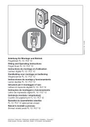
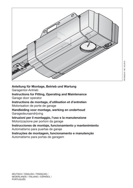
Anleitung für Montage, Betrieb und Wartung<br />
Garagentor-Antrieb<br />
Instructions for Fitting, Operating and Maintenance<br />
Garage door operator<br />
Instructions de montage, d’utilisation et d’entretien<br />
Motorisation de porte de garage<br />
Handleiding voor montage, werking en onderhoud<br />
Garagedeuraandrijving<br />
Istruzioni per il montaggio, l‘uso e la manutenzione<br />
Motorizzazione per portoni da garage<br />
Instrucciones de montaje, funcionamiento y mantenimiento<br />
Automatismo para puertas de garaje<br />
Instruções de montagem, funcionamento e manutenção<br />
Automatismo para portas de garagem<br />
Deutsch / English / Français /<br />
Nederlands / Italiano / Español /<br />
Português
2 TR10A033-E RE / 03.2010
DEUTSCH ........................ 4<br />
ENGLISH ........................ 22<br />
FRANÇAIS ....................... 39<br />
NEDERLANDS. ................... 58<br />
ESPAÑOL. ....................... 76<br />
ITALIANO. ....................... 95<br />
PORTUGUÊS. ................... 114<br />
................... 133<br />
TR10A033-E RE / 03.2010 3
DEUTSCH<br />
Inhaltsverzeichnis<br />
A Mitgelieferte Artikel................................................. 2<br />
B Benötigtes Werkzeug zur Montage....................... 2<br />
1 Zu dieser Anleitung................................................. 5<br />
1.1 Mitgeltende Unterlagen............................................. 5<br />
1.2 Verwendete Warnhinweise........................................ 5<br />
1.3 Verwendete Definitionen............................................ 5<br />
1.4 Verwendete Symbole................................................ 5<br />
1.5 Verwendete Abkürzungen......................................... 6<br />
2 Sicherheitshinweise......................................... 6<br />
2.1 Bestimmungsgemäße Verwendung.......................... 6<br />
2.2 Nicht bestimmungsgemäße Verwendung................. 6<br />
2.3 Qualifikation des Monteurs....................................... 6<br />
2.4 Sicherheitshinweise zur Montage, Wartung,<br />
Reparatur und Demontage der Toranlage................. 6<br />
2.5 Sicherheitshinweise zur Montage.............................. 6<br />
2.6 Sicherheitshinweise zur Inbetriebnahme<br />
und zum Betrieb........................................................ 7<br />
2.7 Sicherheitshinweise zum Gebrauch des<br />
Handsenders............................................................. 7<br />
2.8 Geprüfte Sicherheitseinrichtungen............................ 7<br />
2.9 Sicherheitshinweise zur Prüfung und Wartung......... 7<br />
3 Montage................................................................... 7<br />
3.1 Tor/Toranlage überprüfen.......................................... 7<br />
3.2 Benötigter Freiraum................................................... 7<br />
3.3 Garagentor-Antrieb montieren................................... 8<br />
3.4 Führungsschiene montieren...................................... 8<br />
3.5 Warnschild befestigen............................................... 9<br />
3.6 Garagentor-Antrieb elektrisch anschließen............... 9<br />
3.7 Zusatzkomponenten/Zubehör anschließen............. 10<br />
4 Inbetriebnahme...................................................... 10<br />
4.1 Antrieb in Betrieb nehmen....................................... 11<br />
4.2 Zusätzliche Funktionen über<br />
DIL-Schalter einstellen............................................ 12<br />
5 Funk........................................................................ 13<br />
5.1 Handsender HSM 4................................................. 13<br />
5.2 Integriertes Funkmodul........................................... 14<br />
5.3 Externer Empfänger ............................................... 14<br />
5.4 Auszug aus der Konformitätserklärung für<br />
Empfänger............................................................... 15<br />
6 Betrieb.................................................................... 15<br />
6.1 Benutzer einweisen................................................. 15<br />
6.2 Funktionsprüfung.................................................... 16<br />
6.3 Normal-Betrieb........................................................ 16<br />
6.4 Handbetrieb............................................................. 16<br />
6.5 Betrieb nach mechanischer Entriegelung............... 16<br />
6.6 Verhalten bei einem Spannungsausfall<br />
(ohne Not-Akku)...................................................... 16<br />
6.7 Verhalten nach einem Spannungsausfall<br />
(ohne Not-Akku)...................................................... 16<br />
6.8 Netzausfallüberbrückung mit Not-Akku.................. 16<br />
6.9 Meldungen der Antriebsbeleuchtung...................... 16<br />
6.10 Fehlermeldungen / Diagnose-LED.......................... 17<br />
7 Prüfung und Wartung............................................ 17<br />
7.1 Ersatzlampe............................................................. 17<br />
8 Optionales Zubehör............................................... 18<br />
9 Demontage und Entsorgung................................ 18<br />
10 Garantiebedingungen............................................ 18<br />
10.1 Leistung................................................................... 18<br />
11 Auszug aus der Einbauerklärung......................... 18<br />
12 Technische Daten.................................................. 18<br />
13 Übersicht DIL-Schalter-Funktionen..................... 20<br />
14 Übersicht Fehler und Fehlerbehebung................ 21<br />
Bildteil........................................................ 133<br />
Weitergabe sowie Vervielfältigung dieses Dokuments, Verwertung<br />
und Mitteilung seines Inhalts sind verboten, soweit<br />
nicht ausdrücklich gestattet. Zuwiderhandlungen verpflichten<br />
zu Schadenersatz. Alle Rechte für den Fall der Patent-,<br />
Gebrauchsmuster- oder Geschmacksmustereintragung<br />
vorbehalten. Änderungen vorbehalten.<br />
4 TR10A033-E RE / 03.2010
DEUTSCH<br />
Sehr geehrte Kundin, sehr geehrter Kunde,<br />
wir freuen uns, dass Sie sich für ein Qualitätsprodukt aus<br />
unserem Hause entschieden haben.<br />
1 Zu dieser Anleitung<br />
Diese Anleitung ist eine Originalbetriebsanleitung im Sinne<br />
der EG-Richtlinie 2006/42/EG. Lesen Sie die Anleitung<br />
sorgfältig und vollständig durch, sie enthält wichtige<br />
Informationen zum Produkt. Beachten Sie die Hinweise und<br />
befolgen Sie insbesondere die Sicherheits- und<br />
Warnhinweise.<br />
Bewahren Sie die Anleitung sorgfältig auf und stellen Sie<br />
sicher, dass sie jederzeit verfügbar und vom Benutzer des<br />
Produkts einsehbar ist.<br />
1.1 Mitgeltende Unterlagen<br />
Dem Endverbraucher müssen für die sichere Nutzung und<br />
Wartung der Toranlage folgende Unterlagen zur Verfügung<br />
gestellt werden:<br />
• diese Anleitung<br />
• beigefügtes Prüfbuch<br />
• die Anleitung des Garagentores<br />
1.2<br />
Verwendete Warnhinweise<br />
Das allgemeine Warnsymbol kennzeichnet eine<br />
Gefahr, die zu Verletzungen oder zum Tod führen kann. Im<br />
Textteil wird das allgemeine Warnsymbol in Verbindung mit<br />
den nachfolgend beschriebenen Warnstufen verwendet. Im<br />
Bildteil verweist eine zusätzlich Angabe auf die<br />
Erläuterungen im Textteil.<br />
GEFAHR<br />
Kennzeichnet eine Gefahr, die unmittelbar zum Tod oder zu<br />
schweren Verletzungen führt.<br />
WARNUNG<br />
Kennzeichnet eine Gefahr, die zum Tod oder zu schweren<br />
Verletzungen führen kann.<br />
VORSICHT<br />
Kennzeichnet eine Gefahr, die zu leichten oder mittleren<br />
Verletzungen führen kann.<br />
ACHTUNG<br />
Kennzeichnet eine Gefahr, die zur Beschädigung oder<br />
Zerstörung des Produkts führen kann.<br />
Impuls-Steuerung<br />
Bei jeder Tastenbetätigung wird das Tor entgegen der letzten<br />
Fahrtrichtung gestartet, oder eine Torfahrt wird gestoppt.<br />
Kraft-Lernfahrt<br />
Bei dieser Lernfahrt werden die Kräfte eingelernt, die für das<br />
Verfahren des Tores notwendig sind.<br />
Lichtschranke<br />
Bei Betätigung der Sicherheitseinrichtung Lichtschranke,<br />
während der Fahrt in Richtung Tor-Zu, stoppt das Tor und<br />
reversiert. Die Aufhaltezeit wird neu gestartet.<br />
Normal-Betrieb<br />
Verfahren des Tores mit den eingelernten Strecken und<br />
Kräften.<br />
Referenzfahrt<br />
Torfahrt in Richtung Endlage Tor-Auf, um die Grundstellung zu<br />
setzen.<br />
Reversierfahrt/Sicherheitsrücklauf<br />
Verfahren des Tores in Gegenrichtung beim Ansprechen der<br />
Sicherheitseinrichtung oder Kraftbegrenzung.<br />
Reversiergrenze<br />
Bis zur Reversiergrenze (max. 50 mm), kurz vor der Endlage<br />
Tor-Zu, wird beim Ansprechen einer Sicherheitseinrichtung<br />
eine Fahrt in Gegenrichtung (Reversierfahrt) ausgelöst. Beim<br />
Überfahren dieser Grenze gibt es dieses Verhalten nicht,<br />
damit das Tor ohne Fahrtunterbrechung sicher die Endlage<br />
erreicht.<br />
Strecken-Lernfahrt<br />
Torfahrt, die den Verfahrweg im Antrieb einlernt.<br />
Vorwarnzeit<br />
Die Zeit zwischen dem Fahrbefehl (Impuls) und dem Beginn<br />
der Torfahrt.<br />
Werksreset<br />
Zurücksetzen der eingelernten Werte in den<br />
Auslieferungszustand / die Werkseinstellung.<br />
1.4 Verwendete Symbole<br />
Im Bildteil wird die Antriebsmontage an einem Sectionaltor<br />
dargestellt. Bei Montageabweichungen am Schwingtor<br />
werden diese zusätzlich gezeigt. Hierbei werden folgende<br />
Buchstaben der Bildnummerierung zugeordnet:<br />
1.3<br />
Verwendete Definitionen<br />
a = Sectionaltor<br />
Aufhaltezeit<br />
Wartezeit vor der Zufahrt des Tores aus der Endlage Tor-Auf<br />
bei automatischem Zulauf.<br />
Automatischer Zulauf<br />
Selbsttätiges Schließen des Tores nach Ablauf einer Zeit, aus<br />
der Endlage Tor-Auf.<br />
b = Schwingtor<br />
DIL-Schalter<br />
Auf der Steuerungsplatine befindliche Schalter zum Einstellen<br />
der Steuerung.<br />
Hinweis:<br />
Alle Maßangaben im Bildteil sind in [mm].<br />
TR10A033-E RE / 03.2010 5
DEUTSCH<br />
Einige Bilder beinhalten dieses Symbol mit einem Verweis auf<br />
eine Stelle im Text. Dort erhalten Sie wichtige Informationen<br />
zur Montage und zum Betrieb des Garagentor-Antriebes.<br />
Im Beispiel bedeutet 2.2:<br />
2.2<br />
siehe Textteil, Kapitel 2.2<br />
Außerdem wird im Bild- sowie im Textteil an den Stellen, an<br />
denen die Menüs des Antriebes erklärt werden, das folgende<br />
Symbol dargestellt, welches die Werkseinstellung<br />
kennzeichnet:<br />
Werkseinstellung<br />
2.3 Qualifikation des Monteurs<br />
Nur die korrekte Montage und Wartung durch einen<br />
kompetenten/sachkundigen Betrieb oder eine kompetente/<br />
sachkundige Person in Übereinstimmung mit den Anleitungen<br />
kann die sichere und vorgesehene Funktionsweise einer<br />
Montage sicherstellen. Eine sachkundige Person ist gemäß<br />
EN 12635 eine Person, die über eine geeignete Ausbildung,<br />
qualifiziertes Wissen und praktische Erfahrung verfügt, um<br />
eine Toranlage richtig und sicher zu montieren, zu prüfen und<br />
zu warten.<br />
2.4<br />
Sicherheitshinweise zur Montage, Wartung,<br />
Reparatur und Demontage der Toranlage<br />
GEFAHR<br />
Ausgleichsfedern stehen unter hoher Spannung<br />
▶ Siehe Warnhinweis Kapitel 3.1<br />
1.5<br />
Verwendete Abkürzungen<br />
Farbcode für Leitungen, Einzeladern und Bauteile<br />
Die Abkürzungen der Farben für Leitung- und<br />
Aderkennzeichnung sowie Bauteilen folgen dem<br />
internationalen Farbcode nach IEC 757:<br />
BN Braun WH Weiß<br />
GN Grün YE Gelb<br />
Artikel-Bezeichnungen<br />
HE 1<br />
IT 1<br />
IT 1b<br />
EL 101<br />
EL 301<br />
STK<br />
PR 1<br />
HSM 4<br />
HNA 18<br />
2 Sicherheitshinweise<br />
1-Kanal-Empfänger<br />
Innentaster mit Impuls-Taste<br />
Innentaster mit beleuchteter<br />
Impuls-Taste<br />
Einweg-Lichtschranke<br />
Einweg-Lichtschranke<br />
Schlupftürkontakt<br />
Optionsrelais<br />
4-Tasten-Mini-Handsender<br />
Not-Akku<br />
2.1 Bestimmungsgemäße Verwendung<br />
Der Garagentor-Antrieb ist ausschließlich für den<br />
Impulsbetrieb von federausgeglichenen Sectional- und<br />
Schwingtoren im privaten/nichtgewerblichen Bereich<br />
vorgesehen.<br />
Beachten Sie die Herstellerangaben betreffend der<br />
Kombination von Tor und Antrieb. Mögliche Gefährdungen im<br />
Sinne der DIN EN 13241-1 werden durch die Konstruktion<br />
und Montage nach unseren Vorgaben vermieden. Toranlagen,<br />
die sich im öffentlichen Bereich befinden und nur über eine<br />
Schutzeinrichtung, z.B. Kraftbegrenzung verfügen, dürfen nur<br />
unter Aufsicht betrieben werden.<br />
Der Garagentor-Antrieb ist für den Betrieb in trockenen<br />
Räumen konstruiert.<br />
Die Montage, Wartung, Reparatur und Demontage der<br />
Toranlage und des Garagentor-Antriebes muss durch<br />
Sachkundige ausgeführt werden.<br />
▶ Bei Versagen des Garagentor-Antriebes unmittelbar einen<br />
Sachkundigen mit der Prüfung bzw. der Reparatur<br />
beauftragen.<br />
2.5 Sicherheitshinweise zur Montage<br />
Der Sachkundige muss darauf achten, dass bei der<br />
Durchführung der Montagearbeiten die geltenden Vorschriften<br />
zur Arbeitssicherheit sowie die Vorschriften für den Betrieb<br />
von elektrischen Geräten befolgt werden. Hierbei sind die<br />
nationalen Richtlinien zu beachten. Mögliche Gefährdungen<br />
im Sinne der DIN EN 13241-1 werden durch die Konstruktion<br />
und Montage nach unseren Vorgaben vermieden.<br />
Der Garagentor-Antrieb ist für den Betrieb in trockenen<br />
Räumen konstruiert und darf daher nicht im Freien montiert<br />
werden. Die Garagendecke muss so ausgelegt sein, dass eine<br />
sichere Befestigung des Antriebes gewährleistet ist. Bei zu<br />
hohen oder zu leichten Decken muss der Antrieb an<br />
zusätzlichen Streben befestigt werden.<br />
Netzspannung<br />
▶ Siehe Warnhinweis Kapitel 3.6<br />
gefahr<br />
WARNUNG<br />
Nicht geeignete Befestigungsmaterialien<br />
▶ Siehe Warnhinweis Kapitel 3.3<br />
Lebensgefahr durch Handseil<br />
▶ Siehe Warnhinweis Kapitel 3.3<br />
Verletzungsgefahr durch ungewollte Torbewegung<br />
▶ Siehe Warnhinweis Kapitel 3.3<br />
2.2 Nicht bestimmungsgemäße Verwendung<br />
Der Einsatz im gewerblichen Bereich ist nicht zulässig.<br />
Der Antrieb darf nicht bei Toren ohne Absturzsicherung<br />
verwendet werden.<br />
6 TR10A033-E RE / 03.2010
DEUTSCH<br />
2.6<br />
Sicherheitshinweise zur Inbetriebnahme und<br />
zum Betrieb<br />
WARNUNG<br />
Verletzungsgefahr bei Torbewegung<br />
▶ Siehe Warnhinweis Kapitel 4<br />
Vorsicht<br />
Quetschgefahr in der Führungsschiene<br />
▶ Siehe Warnhinweis Kapitel 4<br />
Verletzungsgefahr durch Seilglocke<br />
▶ Siehe Warnhinweis Kapitel 4<br />
Verletzungsgefahr durch heiße Lampe<br />
▶ Siehe Warnhinweis Kapitel 4, Kapitel 6 und Kapitel 7.1<br />
Verletzungsgefahr bei zu hoch eingestelltem Kraftwert<br />
▶ Siehe Warnhinweis Kapitel 4.1.3<br />
Verletzungsgefahr durch unkontrollierte Torbewegung<br />
in Richtung Tor-Zu bei Bruch der Torsionsfeder und<br />
Entriegelung des Führungsschlittens.<br />
▶ Siehe Warnhinweis Kapitel 3.4.1 und Kapitel 6<br />
2.7<br />
Sicherheitshinweise zum Gebrauch des<br />
Handsenders<br />
WARNUNG<br />
Verletzungsgefahr bei Torbewegung<br />
▶ Siehe Warnhinweis Kapitel 5.1<br />
Vorsicht<br />
Verletzungsgefahr durch unbeabsichtigte Torfahrt<br />
▶ Siehe Warnhinweis Kapitel 5.1<br />
2.8 Geprüfte Sicherheitseinrichtungen<br />
Sicherheitsrelevante Funktionen bzw. Komponenten der<br />
Steuerung, wie die Kraftbegrenzung, externe Lichtschranken,<br />
sofern vorhanden, wurden entsprechend Kategorie 2, PL „c“<br />
der EN ISO 13849-1:2008 konstruiert und geprüft.<br />
WARNUNG<br />
Verletzungsgefahr durch nicht funktionierende<br />
Sicherheitseinrichtungen<br />
▶ Siehe Warnhinweis Kapitel 4.1.2<br />
2.9<br />
Sicherheitshinweise zur Prüfung und Wartung<br />
WARNUNG<br />
Verletzungsgefahr durch unerwartete Torbewegung<br />
▶ Siehe Warnhinweis Kapitel 7<br />
3<br />
Montage<br />
3.1 Tor/Toranlage überprüfen<br />
GEFAHR<br />
Ausgleichsfedern stehen unter hoher Spannung<br />
Das Nachstellen oder Lösen der Ausgleichsfedern kann<br />
ernsthafte Verletzungen verursachen!<br />
▶ Lassen Sie zu Ihrer eigenen Sicherheit Arbeiten an den<br />
Ausgleichsfedern des Tores und falls erforderlich,<br />
Wartungs- und Reparaturarbeiten nur durch einen<br />
Sachkundigen ausführen!<br />
▶ Versuchen Sie niemals, die Ausgleichsfedern für den<br />
Gewichtsausgleich des Tores oder deren Halterungen<br />
selbst auszuwechseln, nachzustellen, zu reparieren<br />
oder zu versetzen.<br />
▶ Kontrollieren Sie außerdem die gesamte Toranlage<br />
(Gelenke, Lager des Tores, Seile, Federn und<br />
Befestigungsteile) auf Verschleiß und eventuelle<br />
Beschädigungen.<br />
▶ Überprüfen Sie auf vorhandenen Rost, Korrosion und<br />
Risse.<br />
Fehler in der Toranlage oder falsch ausgerichtete Tore<br />
können zu schweren Verletzungen führen!<br />
▶ Benutzen Sie die Toranlage nicht, wenn Reparaturoder<br />
Einstellarbeiten durchgeführt werden müssen!<br />
Die Konstruktion des Antriebes ist nicht für den Betrieb<br />
schwergängiger Tore, das heißt Tore, die nicht mehr oder nur<br />
schwer von Hand geöffnet oder geschlossen werden können,<br />
ausgelegt.<br />
Das Tor muss sich mechanisch in einem fehlerfreien Zustand<br />
und im Gleichgewicht befinden, so dass es auch von Hand<br />
leicht zu bedienen ist (EN 12604).<br />
▶ Heben Sie das Tor ca. einen Meter und lassen es los. Das<br />
Tor sollte in dieser Stellung stehen bleiben und sich<br />
weder nach unten noch nach oben bewegen. Bewegt<br />
sich das Tor doch in eine der beiden Richtungen, so<br />
besteht die Gefahr, dass die Ausgleichsfedern/Gewichte<br />
nicht richtig eingestellt oder defekt sind. In diesem Fall ist<br />
mit einer erhöhten Abnutzung und Fehlfunktionen der<br />
Toranlage zu rechnen.<br />
▶ Prüfen Sie, ob sich das Tor richtig öffnen und schließen<br />
lässt.<br />
▶ Setzen Sie die mechanischen Verriegelungen des Tores,<br />
die nicht für eine Betätigung mit einem Garagentor-<br />
Antrieb benötigt werden, außer Betrieb. Hierzu zählen<br />
insbesondere die Verriegelungsmechanismen des<br />
Torschlosses (siehe Kapitel 3.3 und Kapitel 3.6).<br />
▶<br />
Wechseln Sie für die Montage und Inbetriebnahme<br />
zum Bildteil. Beachten Sie den entsprechenden<br />
Textteil, wenn Sie durch das Symbol für den<br />
Textverweis darauf hingewiesen werden.<br />
3.2 Benötigter Freiraum<br />
Der Freiraum zwischen dem höchsten Punkt des Tores und<br />
der Decke muss (auch beim Öffnen des Tores) mindestens<br />
30 mm betragen (siehe Bilder 1.1a/1.1b).<br />
▶ Überprüfen Sie dieses Maß!<br />
Bei einem geringeren Freiraum kann, sofern genügend Platz<br />
vorhanden ist, der Antrieb auch hinter dem geöffneten Tor<br />
montiert werden. In diesen Fällen muss ein verlängerter<br />
Tormitnehmer eingesetzt werden, welcher separat zu<br />
bestellen ist. Außerdem kann der Garagentor-Antrieb<br />
TR10A033-E RE / 03.2010 7
DEUTSCH<br />
max. 50 cm außermittig angeordnet werden. Ausgenommen<br />
sind Sectionaltore mit einer Höherführung (H-Beschlag);<br />
hierbei ist jedoch ein Spezialbeschlag erforderlich. Die<br />
notwendige Steckdose zum elektrischen Anschluss sollte<br />
ca. 50 cm neben dem Antriebskopf montiert werden. Bitte<br />
überprüfen Sie diese Maße!<br />
3.3 Garagentor-Antrieb montieren<br />
WARNUNG<br />
Nicht geeignete Befestigungsmaterialien<br />
Die Verwendung nicht geeigneter Befestigungsmaterialien<br />
kann dazu führen, dass der Antrieb nicht sicher befestigt ist<br />
und sich lösen kann.<br />
▶ Die mitgelieferten Montagematerialien müssen auf Ihre<br />
Eignung für den vorgesehenen Montageort vom<br />
Einbauer überprüft werden.<br />
▶ Verwenden Sie das mitgelieferte Befestigungsmaterial<br />
(Dübel) nur für Beton ≥ B15 (siehe<br />
Bilder 1.6a/1.8b/2.4).<br />
WARNUNG<br />
Lebensgefahr durch Handseil<br />
Ein mitlaufendes Handseil kann zur Strangulierung führen.<br />
▶ Entfernen Sie bei der Antriebsmontage das Handseil<br />
(siehe Bild 1.2a).<br />
WARNUNG<br />
Verletzungsgefahr durch ungewollte<br />
Torbewegung<br />
Bei einer falschen Montage oder<br />
Handhabung des Antriebes können<br />
ungewollte Torbewegungen ausgelöst<br />
und dabei Personen oder Gegenstände<br />
eingeklemmt werden.<br />
▶ Befolgen Sie alle Anweisungen, die<br />
in dieser Anleitung enthalten sind.<br />
Bei falsch angebrachten<br />
Steuerungsgeräten (wie z. B. Taster)<br />
können ungewollte Torbewegungen<br />
ausgelöst und dabei Personen oder<br />
Gegenstände eingeklemmt werden.<br />
▶ Bringen Sie Steuergeräte in einer<br />
Höhe von mindestens 1,5 m an<br />
(außer Reichweite von Kindern).<br />
▶ Montieren Sie festinstallierte<br />
Steuerungsgeräte (wie z. B. Taster)<br />
in Sichtweite des Tores, aber<br />
entfernt von sich bewegenden<br />
Teilen.<br />
ACHTUNG<br />
Beschädigung durch Schmutz<br />
Bohrstaub und Späne können zu Funktionsstörungen<br />
führen.<br />
▶ Decken Sie bei Bohrarbeiten den Antrieb ab.<br />
Hinweis:<br />
Für Garagen ohne einen zweiten Zugang ist eine<br />
Notentriegelung erforderlich, die ein mögliches Aussperren<br />
verhindert; diese muss separat bestellt werden.<br />
▶ Überprüfen Sie die Notentriegelung monatlich auf ihre<br />
Funktionsfähigkeit.<br />
1. Demontieren Sie am Sectionaltor die mechanische<br />
Torverriegelung komplett (siehe Bild 1.3a).<br />
2. Bringen Sie bei Sectionaltoren mit einem mittigen<br />
Torverschluss das Sturzgelenk und den Mitnehmerwinkel<br />
außermittig an (siehe Bild 1.5a).<br />
3. Montieren Sie beim außermittigen Verstärkungsprofil am<br />
Sectionaltor den Mitnehmerwinkel am nächstgelegenen<br />
Verstärkungsprofil rechts oder links (siehe Bild 1.5a).<br />
Hinweis:<br />
Abweichend von Bild 1.5a: Verwenden Sie bei Holztoren die<br />
Holzschrauben 5 x 35 aus dem Beipack des Tores (Bohrung<br />
Ø 3 mm).<br />
4. Setzen Sie die mechanischen Tor-Verriegelungen am<br />
Schwingtor außer Betrieb (siehe Bilder 1.3b/1.4b/1.5b).<br />
Stellen Sie bei den hier nicht aufgeführten Tormodellen<br />
die Schnäpper bauseits fest.<br />
5. Abweichend von Bild 1.6b/1.7b: Bringen Sie bei<br />
Schwingtoren mit einem kunstschmiedeeisernen Torgriff<br />
das Sturzgelenk und den Mitnehmerwinkel außermittig<br />
an.<br />
Hinweis:<br />
Verwenden Sie bei N80-Toren mit Holzfüllung die unteren<br />
Löcher vom Sturzgelenk zur Montage (siehe Bild 1.7b).<br />
3.4<br />
Führungsschiene montieren<br />
Hinweise:<br />
• Bevor die Führungsschiene am Sturz bzw. unter der<br />
Decke montiert wird, muss der Führungsschlitten im<br />
eingekuppelten Zustand (siehe Kapitel 3.4.1) ca. 20 cm<br />
aus der Endlage Tor-Zu in die Richtung der Endlage<br />
Tor-Auf geschoben werden. Dieses ist nicht mehr im<br />
eingekuppelten Zustand möglich, sobald die<br />
Endanschläge und der Antrieb montiert sind (siehe<br />
Bild 2.1).<br />
• Verwenden Sie für die Garagentor-Antriebe – abhängig<br />
vom jeweiligen Einsatzzweck – ausschließlich die von uns<br />
empfohlenen Führungsschienen (siehe<br />
Produktinformation)!<br />
3.4.1 Betriebsarten der Führungsschiene<br />
Bei der Führungsschiene gibt es zwei verschiedene<br />
Betriebsarten:<br />
• Handbetrieb<br />
• Automatikbetrieb<br />
Handbetrieb<br />
▶ Siehe Bild 4<br />
Der Führungsschlitten ist vom Gurt-/Riemenschloss<br />
entkuppelt, sodass das Tor von Hand verfahren werden kann.<br />
Um den Führungsschlitten zu entkuppeln:<br />
▶ Ziehen Sie am Seil der mechanischen Entriegelung.<br />
8 TR10A033-E RE / 03.2010
DEUTSCH<br />
Vorsicht<br />
Verletzungsgefahr durch unkontrollierte Torbewegung<br />
in Richtung Tor-Zu bei Bruch der Torsionsfeder und<br />
Entriegelung des Führungsschlittens.<br />
Ohne die Montage eines Nachrüst-Sets kann der<br />
Führungsschlitten unkontrolliert entriegelt werden.<br />
▶ Der verantwortliche Monteur muss ein Nachrüst-Set<br />
am Führungsschlitten montieren, wenn folgende<br />
Voraussetzungen zutreffen:<br />
– es gilt die Norm DIN EN 13241-1<br />
– Der Garagentor-Antrieb wird von einem<br />
Sachkundigen an einem Hörmann Sectionaltor<br />
ohne Federbruchsicherung (BR30) nachgerüstet.<br />
Dieses Set besteht aus einer Schraube, die den<br />
Führungsschlitten vor dem unkontrollierten Entriegeln<br />
sichert sowie einem neuen Seilglocken-Schild, auf dem die<br />
Bilder zeigen, wie das Set und der Führungsschlitten für die<br />
zwei Betriebsarten von der Führungsschiene zu handhaben<br />
sind.<br />
Hinweis:<br />
Der Einsatz einer Notentriegelung bzw. eines<br />
Notentriegelungsschlosses ist in Verbindung mit dem<br />
Nachrüst-Set nicht möglich.<br />
Automatikbetrieb<br />
▶ Siehe Bild 6<br />
Das Gurt-/Riemenschloss ist im Führungsschlitten<br />
eingekuppelt, sodass das Tor mit dem Antrieb verfahren<br />
werden kann.<br />
Um den Führungsschlitten auf das Einkuppeln<br />
vorzubereiten:<br />
1. Drücken Sie den grünen Knopf.<br />
2. Verfahren Sie den Gurt/Riemen soweit in die Richtung<br />
des Führungsschlittens, bis das Gurt-/Riemenschloss in<br />
diesem einkuppelt.<br />
Vorsicht<br />
Quetschgefahr in der Führungsschiene<br />
Das Greifen in die Führungsschiene während der Torfahrt<br />
kann zu Quetschungen führen.<br />
▶ Greifen Sie während der Torfahrt nicht in die<br />
Führungsschiene<br />
3.4.2 Endlagen durch die Montage der Endanschläge<br />
festlegen<br />
1. Setzen Sie den Endanschlag für die Endlage Tor-Auf<br />
zwischen dem Führungsschlitten und dem Antrieb lose in<br />
die Führungsschiene ein.<br />
2. Schieben Sie das Tor per Hand in die Endlage Tor-Auf.<br />
Der Endanschlag wird dadurch in die richtige Position<br />
geschoben.<br />
3. Fixieren Sie den Endanschlag für die Endlage Tor-Auf<br />
(siehe Bild 5.1).<br />
Hinweis:<br />
Sollte das Tor in der Endlage Tor-Auf nicht die komplette<br />
Durchfahrtshöhe erreichen, kann der Endanschlag entfernt<br />
werden, sodass der integrierte Endanschlag (im Antriebskopf)<br />
zum Einsatz kommt.<br />
4. Setzen Sie den Endanschlag für die Endlage Tor-Zu<br />
zwischen dem Führungsschlitten und dem Tor lose in die<br />
Führungsschiene ein.<br />
5. Schieben Sie das Tor per Hand in die Endlage Tor-Zu.<br />
Der Endanschlag wird dadurch in die Nähe der richtigen<br />
Position geschoben.<br />
6. Schieben Sie nach Erreichen der Endlage Tor-Zu den<br />
Endanschlag ca. 1 cm weiter in die Richtung Tor-Zu und<br />
fixieren Sie den Endanschlag (siehe Bild 5.2).<br />
Hinweis:<br />
Wenn sich das Tor per Hand nicht einfach in die gewünschte<br />
Endlage Tor-Auf bzw. Tor-Zu schieben lässt, so ist die<br />
Tormechanik für den Betrieb mit dem Garagentor-Antrieb zu<br />
schwergängig und muss überprüft werden (siehe<br />
Kapitel 1.1.2)!<br />
3.4.3 Spannung des Zahngurtes/Zahnriemens<br />
Der Zahngurt/Zahnriemen der Führungsschiene besitzt eine<br />
werksseitige optimale Vorspannung. In der Anfahr- und<br />
Abbremsphase kann es bei großen Toren zu einem<br />
kurzzeitigen Heraushängen des Gurtes/Riemens aus dem<br />
Schienenprofil kommen. Dieser Effekt bringt jedoch keine<br />
technischen Einbußen mit sich und wirkt sich auch nicht<br />
nachteilig auf die Funktion und Lebensdauer des Antriebes<br />
aus.<br />
3.5 Warnschild befestigen<br />
Befestigen Sie das Warnschild gegen Einklemmen dauerhaft<br />
an einer auffälligen, gereinigten und entfetteten Stelle, zum<br />
Beispiel in der Nähe der festinstallierten Taster zum Verfahren<br />
des Antriebes.<br />
▶ Siehe Bild 8<br />
3.6 Garagentor-Antrieb elektrisch anschließen<br />
Netzspannung<br />
Gefahr<br />
Bei Kontakt mit der Netzspannung besteht die Gefahr eines<br />
tödlichen Stromschlags.<br />
Beachten Sie daher unbedingt folgende Hinweise:<br />
▶ Elektroanschlüsse dürfen nur von einer Elektrofachkraft<br />
durchgeführt werden.<br />
▶ Die bauseitige Elektroinstallation muss den jeweiligen<br />
Schutzbestimmungen entsprechen (230/240 V AC,<br />
50/60 Hz).<br />
▶ Ziehen Sie vor allen Arbeiten am Antrieb den<br />
Netzstecker.<br />
ACHTUNG<br />
Fremdspannung an den Anschlussklemmen<br />
Fremdspannung an den Anschlussklemmen der Steuerung<br />
führt zur Zerstörung der Elektronik.<br />
▶ Legen Sie an den Anschlussklemmen der Steuerung<br />
keine Netzspannung (230/240 V AC) an.<br />
Um Störungen zu vermeiden:<br />
▶ Verlegen Sie die Steuerleitungen des Antriebes (24 V DC)<br />
in einem getrennten Installationssystem zu anderen<br />
Versorgungsleitungen (230 V AC).<br />
TR10A033-E RE / 03.2010 9
DEUTSCH<br />
3.6.1<br />
Elektrischer Anschluss/Anschlussklemmen<br />
▶ Siehe Bild 9<br />
▶ Nehmen Sie die Steckerabdeckung ab, um die<br />
Anschlussklemmen zu erreichen.<br />
Hinweis:<br />
Alle Anschlussklemmen sind mehrfach belegbar. Beachten<br />
Sie jedoch folgende Stärken (siehe Bild 10):<br />
• Mindeststärke: 1 x 0,5 mm2<br />
• Maximalstärke: 1 x 2,5 mm2<br />
3.7<br />
Zusatzkomponenten/Zubehör anschließen<br />
Hinweis:<br />
Das gesamte Zubehör darf den Antrieb mit max. 100 mA<br />
belasten.<br />
3.7.1 Externe Taster *<br />
Externe Taster dienen zum Auslösen oder Stoppen von<br />
Torfahrten. Ein oder mehrere Taster mit Schließerkontakten<br />
(potenzialfrei), z. B. Innen- oder Schlüsseltaster, können<br />
parallel angeschlossen werden (siehe Bild 11/12).<br />
3.7.2 Zusätzlicher externer Funkempfänger *<br />
Zusätzlich oder anstatt eines integrierten Funkmoduls (siehe<br />
Kap. 5.2) kann ein externer Empfänger für die Funktion Impuls<br />
angeschlossen werden.<br />
▶ Stecker des Empfängers auf den entsprechenden<br />
Steckplatz stecken (siehe Bild 13).<br />
▶ Um den externen Empfänger in Betrieb zu nehmen, die<br />
Daten eines integrierten Funkmoduls löschen (siehe<br />
Kap. 5.2.2).<br />
3.7.3 2-Draht-Lichtschranke *<br />
▶ Schließen Sie Lichtschranken wie in Bild 14 gezeigt an.<br />
Nach dem Auslösen der Lichtschranke stoppt der Antrieb und<br />
es erfolgt ein Sicherheitsrücklauf des Tores in die Endlage<br />
Tor-Auf.<br />
Hinweis:<br />
Sender- und Empfänger-Gehäuse der Lichtschranke so nah<br />
wie möglich am Boden montieren, siehe Anleitung der<br />
Lichtschranke.<br />
3.7.4 Schlupftürkontakt STK *<br />
▶ Zwangsöffnenden Schlupftürkontakt mit Testung<br />
anschließen, wie in Bild 15 dargestellt.<br />
Durch das Öffnen des Schlupftürkontaktes werden Torfahrten<br />
sofort angehalten und dauerhaft unterbunden.<br />
3.7.5 Optionsrelais PR 1 *<br />
▶ Optionsrelais anschließen, wie in Bild 16 dargestellt.<br />
Das Optionsrelais PR 1 kann für die Endlagenmeldung Tor-Zu<br />
und die Lichtsteuerung verwendet werden.<br />
3.7.6 Not-Akku HNA 18 *<br />
▶ Not-Akku anschließen, wie in Bild 22 dargestellt.<br />
Um bei einem Netzausfall das Tor verfahren zu können, ist ein<br />
optionaler Not-Akku anschließbar. Die Umschaltung auf Akku-<br />
Betrieb bei Netzausfall erfolgt automatisch. Während des<br />
Akku-Betriebes bleibt die Antriebsbeleuchtung ausgeschaltet.<br />
WARNUNG<br />
Verletzungsgefahr durch unerwartete Torfahrt<br />
Zu einer unerwarteten Torfahrt kann es kommen, wenn trotz<br />
gezogenem Netzstecker noch der Not-Akku angeschlossen<br />
ist.<br />
▶ Ziehen Sie bei allen Arbeiten an der Toranlage den<br />
Netzstecker und den Stecker des Not-Akkus.<br />
4 Inbetriebnahme<br />
WARNUNG<br />
Verletzungsgefahr bei Torbewegung<br />
Im Bereich des Tores kann es bei<br />
fahrendem Tor zu Verletzungen oder<br />
Beschädigungen kommen.<br />
▶ Kinder dürfen nicht an der<br />
Toranlage spielen.<br />
▶ Stellen Sie sicher, dass sich im<br />
Bewegungsbereich des Tores keine<br />
Personen oder Gegenstände<br />
befinden.<br />
▶ Betreiben Sie den Garagentor-<br />
Antrieb nur, wenn Sie den<br />
Bewegungsbereich des Tores<br />
einsehen können und dieses nur<br />
über eine Sicherheitseinrichtung<br />
verfügt.<br />
▶ Überwachen Sie den Torlauf, bis<br />
das Tor die Endlage erreicht hat.<br />
▶ Durchfahren bzw. durchgehen Sie<br />
Toröffnungen von ferngesteuerten<br />
Toranlagen erst, wenn das<br />
Garagentor in der Endlage Tor‐Auf<br />
steht!<br />
▶ Bleiben Sie niemals unter dem<br />
geöffneten Tor stehen.<br />
Vorsicht<br />
Quetschgefahr in der Führungsschiene<br />
Das Greifen in die Führungsschiene während der Torfahrt<br />
kann zu Quetschungen führen.<br />
▶ Greifen Sie während der Torfahrt nicht in die<br />
Führungsschiene<br />
Vorsicht<br />
Verletzungsgefahr durch Seilglocke<br />
Wenn Sie sich an die Seilglocke hängen, können Sie<br />
abstürzen und sich verletzen. Der Antrieb kann abreißen<br />
und darunter befindliche Personen verletzen, Gegenstände<br />
beschädigen oder selbst zerstört werden.<br />
▶ Hängen Sie sich nicht mit dem Körpergewicht an die<br />
Seilglocke.<br />
* Zubehör, ist nicht in der Standard-Ausstattung enthalten!<br />
10 TR10A033-E RE / 03.2010
DEUTSCH<br />
Vorsicht<br />
Verletzungsgefahr durch heiße Lampe<br />
Das Anfassen der Lampe während oder direkt nach dem<br />
Betrieb kann zu Verbrennungen führen.<br />
▶ Fassen Sie die Lampe nicht an, wenn diese<br />
eingeschaltet ist bzw. unmittelbar nachdem diese<br />
eingeschaltet war.<br />
4.1 Antrieb in Betrieb nehmen<br />
Der Antrieb hat einen spannungsausfallsicheren Speicher, in<br />
dem beim Einlernen die torspezifischen Daten (Verfahrweg,<br />
während der Torfahrt benötigte Kräfte usw.) abgelegt und bei<br />
darauf folgenden Torfahrten aktualisiert werden. Diese Daten<br />
sind nur für dieses Tor gültig und müssen daher für einen<br />
Einsatz an einem anderen Tor oder wenn sich das Tor in<br />
seinem Laufverhalten stark geändert hat (z. B. bei<br />
nachträglichem Versetzen der Endanschläge oder dem Einbau<br />
neuer Federn usw.), gelöscht und wieder neu eingelernt<br />
werden.<br />
4.1.1 Tordaten löschen<br />
▶ Siehe Bild 18<br />
Im Auslieferungszustand sind keine Tordaten gespeichert und<br />
der Antrieb kann sofort eingelernt werden (siehe Kap. 4.1.2).<br />
Wenn ein erneutes Einlernen erforderlich ist, können die<br />
Tordaten wie folgt gelöscht werden:<br />
1. Netzstecker ziehen.<br />
2. Transparenten Taster im Gehäuse drücken und gedrückt<br />
halten.<br />
3. Netzstecker einstecken und den transparenten Taster im<br />
Gehäuse solange gedrückt halten, bis die<br />
Antriebsbeleuchtung einmal blinkt.<br />
Die Tordaten werden gelöscht und der Antrieb kann<br />
sofort eingelernt werden.<br />
4.1.2 Antrieb einlernen<br />
Beim Einlernen werden unter anderem der Verfahrweg und die<br />
während der Auf- bzw. Zufahrt benötigten Kräfte eingelernt<br />
und spannungsausfallsicher gespeichert.<br />
HinweisE:<br />
• Bevor der Antrieb erneut eingelernt werden kann, müssen<br />
vorhandene Tordaten gelöscht werden (siehe Kap. 4.1.1).<br />
• Beim Einlernen ist eine eventuell angeschlossene<br />
Lichtschranke nicht aktiv.<br />
Um den Antrieb einzulernen:<br />
1. Falls erforderlich, den ausgekuppelten Führungsschlitten<br />
durch Druck auf den grünen Knopf am Führungsschlitten<br />
zum Einkuppeln vorbereiten (siehe Bild 6). Dazu das Tor<br />
per Hand verfahren, bis der Führungsschlitten in das<br />
Gurtschloss einkuppelt.<br />
2. Falls erforderlich, den Netzstecker einstecken.<br />
Die Antriebsbeleuchtung blinkt dann zweimal<br />
(siehe Bild 19).<br />
3. Transparenten Taster in der Antriebshaube betätigen<br />
(siehe Bild 19).<br />
Das Tor fährt automatisch auf. Die Antriebsbeleuchtung<br />
blinkt.<br />
4. Transparenten Taster in der Antriebshaube erneut<br />
betätigen (siehe Bild 19).<br />
a. Das Tor fährt automatisch zu, auf, zu und wieder auf.<br />
Während dieser Fahrten blinkt die<br />
Antriebsbeleuchtung und der Verfahrweg und die<br />
benötigten Kräfte werden eingelernt.<br />
b. Das Tor bleibt in der Position Tor-Auf stehen und die<br />
Antriebsbeleuchtung leuchtet kontinuierlich.<br />
Der Antrieb ist betriebsbereit eingelernt.<br />
WARNUNG<br />
Verletzungsgefahr durch nicht funktionierende<br />
Sicherheitseinrichtungen<br />
Durch nicht funktionierende Sicherheitseinrichtungen kann<br />
es im Fehlerfall zu Verletzungen kommen.<br />
▶ Nach den Lernfahrten muss der Inbetriebnehmer die<br />
Funktion(en) der Sicherheitseinrichtung(en) sowie die<br />
Einstellungen überprüfen (siehe Kap. 4.2).<br />
Erst im Anschluss daran ist die Anlage betriebsbereit.<br />
HinweisE:<br />
• Wenn der Antrieb mit blinkender Beleuchtung stehen<br />
bleibt oder die Endanschläge nicht erreicht, sind die<br />
Maximalkräfte zu gering und müssen nachgestellt werden<br />
(siehe Kap. 4.1.3).<br />
• Der Einlernvorgang kann jederzeit durch einen<br />
Fahrtimpuls unterbrochen werden. Ein weiterer<br />
Fahrtimpuls startet den gesamten Einlernvorgang erneut.<br />
4.1.3<br />
Kräfte einstellen<br />
VORSICHT<br />
Verletzungsgefahr bei zu hoch eingestelltem Kraftwert<br />
(Potentiometer P1/P2)<br />
Bei einem zu hoch eingestellten Kraftwert ist die<br />
Kraftbegrenzung unempfindlicher. Dieses kann zu<br />
Verletzungen oder Beschädigungen führen.<br />
▶ Stellen Sie keinen zu hohen Kraftwert ein.<br />
Die beim Einlernen benötigten Kräfte werden auch bei den<br />
darauffolgenden Torfahrten automatisch nachgestellt. Es ist<br />
aus Sicherheitsgründen notwendig, dass sich die Kräfte bei<br />
langsam schlechter werdendem Laufverhalten des Tores<br />
(z. B. Nachlassen der Federspannung) nicht unbegrenzt<br />
nachstellen. Andernfalls können bei Handbetätigung des<br />
Tores Sicherheitsrisiken auftreten (z. B. Torabsturz).<br />
Aus diesem Grund wurden die für die Auf- und Zufahrt zur<br />
Verfügung stehenden Maximalkräfte im Auslieferzustand<br />
begrenzt voreingestellt (Mittelstellung der Potenziometer).<br />
Wenn beim Einlernen des Antriebs (siehe Kap. 4.1.2) eine<br />
oder beide Endlagen nicht erreicht wurden, müssen die Kräfte<br />
nachgestellt werden.<br />
Dazu stehen zwei Potenziometer zur Verfügung, die nach dem<br />
Abnehmen der Antriebshaube zugänglich sind (siehe Bild 20):<br />
• P1: Maximalkraft in Richtung Tor-Auf<br />
• P2: Maximalkraft in Richtung Tor-Zu<br />
Durch Drehen im Uhrzeigersinn werden die Kräfte erhöht und<br />
Drehen entgegen dem Uhrzeigersinn werden die Kräfte<br />
verringert.<br />
TR10A033-E RE / 03.2010 11
DEUTSCH<br />
Wenn der Endanschlag Tor-Auf nicht erreicht wird:<br />
1. P1 um eine Achteldrehung im Uhrzeigersinn verstellen<br />
(siehe Bild 20).<br />
2. Tor durch Drücken auf den transparenten Taster in die<br />
Endlage Tor-Zu fahren, vor dem Erreichen der Endlage<br />
Tor-Zu das Tor durch einen erneuten Tastendruck<br />
stoppen.<br />
3. Tor in Richtung Tor-Auf fahren.<br />
Wenn der Endanschlag Tor-Auf erneut nicht erreicht wird,<br />
Schritte 1 bis 3 wiederholen.<br />
Wenn der Endanschlag Tor-Zu nicht erreicht wird:<br />
1. P2 um eine Achteldrehung im Uhrzeigersinn verstellen<br />
(siehe Bild 20).<br />
2. Tordaten löschen.<br />
3. Antrieb erneut Einlernen (siehe Kap. 4.1.2).<br />
Wenn der Endanschlag Tor-Zu erneut nicht erreicht wird,<br />
Schritte 1 bis 3 wiederholen.<br />
Hinweis:<br />
Die am Potenziometer eingestellten Maximalkräfte haben<br />
einen geringen Einfluss auf die Empfindlichkeit der<br />
Kraftbegrenzung, da die tatsächlich benötigten Kräfte<br />
während der Einlernfahrt gespeichert wurden. Die werkseitig<br />
eingestellten Kräfte passen für den Betrieb von Standard-<br />
Toren.<br />
4.2 Zusätzliche Funktionen über DIL-Schalter<br />
einstellen<br />
Einige Funktionen des Antriebs werden mittels DIL-Schalter<br />
programmiert. Vor der ersten Inbetriebnahme befinden sich<br />
die DIL-Schalter in der Werkseinstellung, d. h. die Schalter<br />
stehen auf OFF (siehe Bild 9).<br />
Hinweis:<br />
Ändern Sie die DIL-Schaltereinstellungen nur, wenn der<br />
Antrieb ruht und kein Funk programmiert wird.<br />
Stellen Sie entsprechend der nationalen Vorschriften, den<br />
gewünschten Sicherheitseinrichtungen und den örtlichen<br />
Gegebenheiten die DIL-Schalter ein, wie nachfolgend<br />
beschrieben.<br />
4.2.1 Endlagenmeldung Tor-Zu: DIL-Schalter A und B<br />
▶ Siehe Bild 17.1<br />
A OFF<br />
B ON<br />
Endlagenmeldung Tor-Zu aktiviert<br />
Tab. 1: Funktion der Antriebsbeleuchtung und des<br />
Optionsrelais bei aktivierter Endlagenmeldung Tor-Zu<br />
Antriebsbeleuchtung<br />
Optionsrelais<br />
4.2.2<br />
▶ Siehe Bild 17.2<br />
A ON<br />
B OFF<br />
• Dauerlicht während der Torfahrt<br />
• Nachleuchtzeit nach Endlage<br />
Tor-Zu<br />
Endlagenmeldung Tor-Zu<br />
Vorwarnzeit: DIL-Schalter A und B<br />
Vorwarnzeit aktiviert<br />
Tab. 2: Funktion der Antriebsbeleuchtung und des<br />
Optionsrelais bei aktivierter Vorwarnzeit<br />
Antriebsbeleuchtung<br />
Optionsrelais<br />
• Schnelles Blinken während der<br />
Vorwarnzeit<br />
• Dauerlicht während der Torfahrt<br />
Taktet während der Torfahrt langsam<br />
(Funktion einer selbstblinkenden<br />
Warnleuchte)<br />
4.2.3 Externe Beleuchtung: DIL-Schalter A und B<br />
▶ Siehe Bild 17.3<br />
A OFF<br />
B OFF<br />
Externe Beleuchtung aktiviert<br />
Tab. 3: Funktion der Antriebsbeleuchtung und des<br />
Optionsrelais bei aktivierter externer Beleuchtung<br />
Antriebsbeleuchtung<br />
Optionsrelais<br />
• Dauerlicht während der Torfahrt<br />
• Nachleuchtzeit nach Endlage<br />
Tor-Zu<br />
Gleiche Funktion wie<br />
Antriebsbeleuchtung<br />
4.2.4 Automatischer Zulauf: DIL-Schalter A, B und D<br />
Nach Erreichen der Endlage Tor-Auf wird nach Ablauf der<br />
Aufhaltezeit von ca. 30 s der automatische Zulauf gestartet.<br />
Nach einem Impuls, einer Durchfahrt oder einem Durchgang<br />
der Lichtschranke wird die Aufhaltezeit automatisch um<br />
ca. 30 s verlängert.<br />
HinweisE:<br />
• Der automatische Zulauf darf im Gültigkeitsbereich der<br />
DIN EN 12453 nur aktiviert werden, wenn eine<br />
Sicherheitseinrichtung angeschlossen ist.<br />
• Das Einstellen des automatischen Zulaufes ist nur mit<br />
aktivierter Lichtschranke möglich (DIL Schalter D auf<br />
ON).<br />
▶ Siehe Bild 17.4<br />
A ON<br />
B ON<br />
D ON<br />
Automatischer Zulauf aktiviert<br />
Tab. 4: Funktion des Antriebes, der Antriebsbeleuchtung und<br />
des Optionsrelais bei aktiviertem automatischen Zulauf<br />
Antrieb<br />
Antriebsbeleuchtung<br />
Optionsrelais<br />
Nach Aufhaltezeit und Vorwarnzeit<br />
automatischer Zulauf aus Endlage<br />
Tor-Auf<br />
• Dauerlicht während der<br />
Aufhaltezeit und der Torfahrt<br />
• Blinkt während der Vorwarnzeit<br />
schnell<br />
• Dauerkontakt bei Aufhaltezeit<br />
• Taktet während der Vorwarnzeit<br />
schnell und während der<br />
Torfahrt langsam<br />
12 TR10A033-E RE / 03.2010
DEUTSCH<br />
4.2.5<br />
▶ Siehe Bild 17.5<br />
C ON<br />
C OFF<br />
4.2.6<br />
▶ Siehe Bild 17.6<br />
D ON<br />
D OFF<br />
Tortyp: DIL-Schalter C<br />
Schwingtor, lange Sanftstopp-Rampe<br />
Sectionaltor, kurze Sanftstopp-Rampe<br />
Lichtschranke: DIL-Schalter D<br />
Aktiviert, nach Auslösen der Lichtschranke<br />
reversiert das Tor bis in die Endlage<br />
Tor-Auf<br />
Nicht aktiviert, automatischer Zulauf nicht<br />
möglich (DIL-Schalter A/B)<br />
4.2.7 Halt-/Ruhestromkreis mit Testung:<br />
DIL‐Schalter E<br />
▶ Siehe Bild 17.7<br />
E ON<br />
E OFF<br />
Aktiviert, für Schlupftürkontakt mit Testung<br />
Nicht aktiviert<br />
Hinweis:<br />
Sicherheitseinrichtungen ohne Testung halbjährlich prüfen.<br />
4.2.8 Tor-Wartungsanzeige: DIL-Schalter F<br />
▶ Siehe Bild 17.8<br />
F ON<br />
F OFF<br />
Aktiviert, das Überschreiten des<br />
Wartungszyklus wird durch mehrmaliges<br />
Blinken der Antriebsbeleuchtung nach<br />
Ende jeder Torfahrt signalisiert.<br />
Nicht aktiviert, kein Signal nach<br />
Überschreiten des Wartungszyklus<br />
Das Wartungsintervall wird erreicht, wenn seit dem letzten<br />
Einlernen entweder der Antrieb länger als 1 Jahr betrieben<br />
wurde oder der Antrieb 2000 Torschließungen erreicht oder<br />
überschritten hat.<br />
Hinweis:<br />
Durch erneutes Einlernen des Antriebs (siehe Kap. 4.1.2)<br />
werden die Wartungsdaten zurückgesetzt.<br />
5 Funk<br />
5.1 Handsender HSM 4<br />
WARNUNG<br />
Verletzungsgefahr bei Torbewegung<br />
Wird der Handsender bedient, können<br />
Personen durch die Torbewegung<br />
verletzt werden.<br />
▶ Stellen Sie sicher, dass Handsender<br />
nicht in Kinderhände gelangen und<br />
nur von Personen benutzt werden,<br />
die in die Funktionsweise der ferngesteuerten<br />
Toranlage eingewiesen<br />
sind!<br />
▶ Sie müssen den Handsender<br />
generell mit Sichtkontakt zum Tor<br />
bedienen, wenn dieses nur über<br />
eine Sicherheitseinrichtung verfügt!<br />
▶ Durchfahren bzw. durchgehen Sie<br />
Toröffnungen von ferngesteuerten<br />
Toranlagen erst, wenn das<br />
Garagentor in der Endlage Tor‐Auf<br />
steht!<br />
▶ Bleiben Sie niemals unter dem<br />
geöffneten Tor stehen.<br />
▶ Beachten Sie, dass am Handsender<br />
versehentlich eine Taste betätigt<br />
werden kann (z. B. in der Hosen-/<br />
Handtasche) und es hierbei zu einer<br />
ungewollten Torfahrt kommen kann.<br />
Vorsicht<br />
Verletzungsgefahr durch unbeabsichtigte Torfahrt<br />
Während des Lernvorgangs am Funk-System kann es zu<br />
unbeabsichtigten Torfahrten kommen.<br />
▶ Achten Sie darauf, dass sich beim Einlernen des<br />
Funk‐Systems keine Personen oder Gegenstände im<br />
Bewegungsbereich des Tores befinden.<br />
ACHTUNG<br />
Beeinträchtigung der Funktion durch Umwelteinflüsse<br />
Bei Nichtbeachtung kann die Funktion beeinträchtigt werden!<br />
Schützen Sie den Handsender vor folgenden Einflüssen:<br />
• direkter Sonneneinstrahlung (zul.<br />
Umgebungstemperatur: -20 °C bis +60 °C)<br />
• Feuchtigkeit<br />
• Staubbelastung<br />
HinweisE:<br />
• Ist kein separater Zugang zur Garage vorhanden, so<br />
führen Sie jede Änderung oder Erweiterung von<br />
Programmierungen innerhalb der Garage durch.<br />
• Führen Sie nach dem Programmieren oder Erweitern des<br />
Funksystems eine Funktionsprüfung durch.<br />
• Verwenden Sie für die Inbetriebnahme oder die<br />
Erweiterung des Funksystems ausschließlich<br />
Originalteile.<br />
• Die örtlichen Gegebenheiten können Einfluss auf die<br />
Reichweite des Funk-Systems haben. Außerdem können<br />
GSM-900-Handys bei gleichzeitiger Benutzung die<br />
Reichweite beeinflussen.<br />
TR10A033-E RE / 03.2010 13
DEUTSCH<br />
5.1.1<br />
▶ Siehe Bild 23<br />
Beschreibung des Handsenders HSM 4<br />
1 LED<br />
2 Handsendertasten<br />
3 Batteriefachdeckel<br />
4 Batterie<br />
5 Reset-Taster<br />
6 Handsenderhalterung<br />
5.1.2<br />
Batterie einlegen/wechseln<br />
▶ Siehe Bild 23<br />
▶ Verwenden Sie ausschließlich den Batterie-Typ 23A<br />
5.1.3<br />
▶ Siehe Bild 23<br />
Wiederherstellen des Werkscodes<br />
Jeder Handsendertaste ist ein Funkcode hinterlegt. Der<br />
ursprüngliche Werkscode kann durch folgende Schritte<br />
wieder hergestellt werden.<br />
Hinweis:<br />
Nachfolgende Bedienschritte sind nur bei versehentlichen<br />
Erweiterungs- oder Lernvorgängen erforderlich.<br />
1. Öffnen Sie den Batteriefachdeckel.<br />
Der Reset-Taster (5) ist auf der Platine zugänglich.<br />
Achtung<br />
Zerstörung des Tasters<br />
▶ Verwenden Sie keine spitzen Gegenstände und drücken<br />
Sie nicht zu stark auf den Taster.<br />
2. Drücken Sie den Reset-Taster mit einem stumpfen<br />
Gegenstand vorsichtig und halten Sie ihn gedrückt.<br />
3. Drücken Sie die Handsendertaste, die codiert werden<br />
soll, und halten Sie diese gedrückt.<br />
Die LED des Senders blinkt langsam.<br />
4. Wenn Sie den kleinen Taster bis zum Ende des langsamen<br />
Blinkens gedrückt halten, wird die Handsendertaste<br />
wieder mit dem ursprünglichen Werkscode belegt und die<br />
LED beginnt schneller zu blinken.<br />
5. Schließen Sie den Batteriefachdeckel.<br />
Der Werkscode ist wieder hergestellt.<br />
5.1.4 Auszug aus der Konformitätserklärung für<br />
Handsender<br />
Die Übereinstimmung des oben genannten Produkts mit den<br />
Vorschriften der Richtlinien gem. Artikel 3 der R&TTE-<br />
Richtlinien 1999/5/EG wurde nachgewiesen durch die<br />
Einhaltung folgender Normen:<br />
• EN 60950:2000<br />
• EN 300 220-1<br />
• EN 300 220-3<br />
• EN 301 489-1<br />
• EN 300 489-3<br />
Die Original-Konformitätserklärung kann beim Hersteller<br />
angefordert werden.<br />
5.2 Integriertes Funkmodul<br />
Bei einem integrierten Funkmodul können die Funktionen<br />
Impuls (Auf-Stop-Zu-Stop) auf je max. 6 verschiedene<br />
Handsender eingelernt werden. Werden mehr als 6 Handsender<br />
eingelernt, werden die Funktionen auf dem zuerst<br />
eingelernten gelöscht.<br />
Um das Funkmodul zu programmieren oder seine Daten zu<br />
löschen, müssen folgende Vorraussetzungen erfüllt sind:<br />
• Die Antrieb ruht.<br />
• Keine Vorwarn- oder Aufhaltezeit ist aktiv.<br />
HinweisE:<br />
• Zum Betrieb des Antriebes mit Funk muss eine<br />
Handsendertaste auf ein integriertes Funkmodul oder<br />
einen externen Funkempfänger eingelernt werden.<br />
• Der Abstand zwischen Handsender und Antrieb sollte<br />
mindestens 1 m betragen.<br />
• GSM-900-Handys können bei gleichzeitiger Benutzung<br />
die Reichweite der Funkfernsteuerung beeinflussen.<br />
5.2.1 Einlernen der Funktion Impuls<br />
1. Taster P in der Antriebshaube einmal kurz drücken<br />
(siehe Bild 21). Weiteres zweimaliges Drücken des<br />
Tasters P beendet die Funk-Programmierbereitschaft<br />
sofort.<br />
Die rote LED im Taster der Antriebshaube blinkt nun 1x.<br />
In dieser Zeit kann eine Handsendertaste für die<br />
gewünschte Funktion programmiert werden.<br />
2. Die Handsendertaste, die programmiert werden soll, so<br />
lange drücken, bis die rote LED im Taster der<br />
Antriebshaube schnell blinkt.<br />
Der Funk-Code dieser Handsendertaste ist nun im<br />
integrierten Funkmodul gespeichert.<br />
5.2.2 Löschen aller Daten in einem integrierten<br />
Funkmodul<br />
1. Taster P in der Antriebshaube drücken und gedrückt<br />
halten.<br />
Die rote LED im Taster der Antriebshaube blinkt langsam<br />
und signalisiert die Löschbereitschaft.<br />
Das Blinken wechselt in einen schnelleren Rhythmus.<br />
Nun sind alle eingelernten Funk-Codes aller Handsender<br />
gelöscht.<br />
2. Taster P in der Antriebshaube loslassen.<br />
5.3 Externer Empfänger *<br />
Anstatt eines integrierten Funkmoduls kann zum Ansteuern<br />
des Garagentor-Antriebes ein externer Empfänger für die<br />
Funktion Impuls verwendet werden.<br />
5.3.1 Externen Empfänger anschließen<br />
1. Stecker eines externen Empfängers auf den<br />
entsprechenden Steckplatz stecken (siehe Bild 13).<br />
Die Adern des externen Empfängers müssen wie folgt<br />
angeschlossen sein:<br />
– GN an die Klemme 20 (0 V)<br />
– WH an die Klemme 21 (Signal für die Impulssteuerung<br />
Kanal 1)<br />
– BN an die Klemme 5 (+24 V)<br />
2. Die Daten eines integrierten Funkmoduls löschen, um<br />
Doppelbelegungen zu vermeiden (siehe Kap. 5.2.2).<br />
5.3.2 Einlernen von Handsendertasten<br />
▶ Funktion Impuls<br />
1. Die Handsendertaste für die Funktion Impuls (Kanal 1) an<br />
Hand der Bedienungsanleitung für den externen<br />
Empfänger einlernen.<br />
Hinweis:<br />
Die Antennenlitze vom externen Empfänger sollte nicht mit<br />
Gegenständen aus Metall (Nägel, Streben, usw.) in<br />
Verbindung kommen. Die beste Ausrichtung muss durch<br />
Versuche ermittelt werden. GSM-900-Handys können bei<br />
gleichzeitiger Benutzung die Reichweite der<br />
Funkfernsteuerung beeinflussen.<br />
* Zubehör, ist nicht in der Standard-Ausstattung enthalten!<br />
14 TR10A033-E RE / 03.2010
DEUTSCH<br />
5.4<br />
Auszug aus der Konformitätserklärung für<br />
Empfänger<br />
Die Übereinstimmung des oben genannten Produkts mit den<br />
Vorschriften der Richtlinien gem. Artikel 3 der R&TTE-<br />
Richtlinien 1999/5/EG wurde nachgewiesen durch die<br />
Einhaltung folgender Normen:<br />
• EN 60950:2000<br />
• EN 300 220-1<br />
• EN 300 220-3<br />
• EN 301 489-1<br />
• EN 300 489-3<br />
Die Original-Konformitätserklärung kann beim Hersteller<br />
angefordert werden.<br />
6 Betrieb<br />
WARNUNG<br />
Verletzungsgefahr bei Torbewegung<br />
Im Bereich des Tores kann es bei<br />
fahrendem Tor zu Verletzungen oder<br />
Beschädigungen kommen.<br />
▶ Kinder dürfen nicht an der<br />
Toranlage spielen.<br />
▶ Stellen Sie sicher, dass sich im<br />
Bewegungsbereich des Tores keine<br />
Personen oder Gegenstände<br />
befinden.<br />
▶ Betreiben Sie den Garagentor-<br />
Antrieb nur, wenn Sie den<br />
Bewegungsbereich des Tores<br />
einsehen können und dieses nur<br />
über eine Sicherheitseinrichtung<br />
verfügt.<br />
▶ Überwachen Sie den Torlauf, bis<br />
das Tor die Endlage erreicht hat.<br />
▶ Durchfahren bzw. durchgehen Sie<br />
Toröffnungen von ferngesteuerten<br />
Toranlagen erst, wenn das<br />
Garagentor in der Endlage Tor‐Auf<br />
steht!<br />
▶ Bleiben Sie niemals unter dem<br />
geöffneten Tor stehen.<br />
Vorsicht<br />
Quetschgefahr in der Führungsschiene<br />
Das Greifen in die Führungsschiene während der Torfahrt<br />
kann zu Quetschungen führen.<br />
▶ Greifen Sie während der Torfahrt nicht in die<br />
Führungsschiene<br />
Vorsicht<br />
Verletzungsgefahr durch Seilglocke<br />
Wenn Sie sich an die Seilglocke hängen, können Sie<br />
abstürzen und sich verletzen. Der Antrieb kann abreißen<br />
und darunter befindliche Personen verletzen, Gegenstände<br />
beschädigen oder selbst zerstört werden.<br />
▶ Hängen Sie sich nicht mit dem Körpergewicht an die<br />
Seilglocke.<br />
Vorsicht<br />
Verletzungsgefahr durch unkontrollierte Torbewegung<br />
in Richtung Tor-Zu bei Bruch der Torsionsfeder und<br />
Entriegelung des Führungsschlittens.<br />
Ohne die Montage eines Nachrüst-Sets kann der<br />
Führungsschlitten unkontrolliert entriegelt werden.<br />
▶ Der verantwortliche Monteur muss ein Nachrüst-Set<br />
am Führungsschlitten montieren, wenn folgende<br />
Voraussetzungen zutreffen:<br />
– es gilt die Norm DIN EN 13241-1<br />
– Der Garagentor-Antrieb wird von einem<br />
Sachkundigen an einem Hörmann Sectionaltor<br />
ohne Federbruchsicherung (BR30) nachgerüstet.<br />
Dieses Set besteht aus einer Schraube, die den<br />
Führungsschlitten vor dem unkontrollierten Entriegeln<br />
sichert sowie einem neuen Seilglocken-Schild, auf dem die<br />
Bilder zeigen, wie das Set und der Führungsschlitten für die<br />
zwei Betriebsarten von der Führungsschiene zu handhaben<br />
sind.<br />
Hinweis:<br />
Der Einsatz einer Notentriegelung bzw. eines<br />
Notentriegelungsschlosses ist in Verbindung mit dem<br />
Nachrüst-Set nicht möglich.<br />
Vorsicht<br />
Verletzungsgefahr durch heiße Lampe<br />
Das Anfassen der Lampe während oder direkt nach dem<br />
Betrieb kann zu Verbrennungen führen.<br />
▶ Fassen Sie die Lampe nicht an, wenn diese<br />
eingeschaltet ist bzw. unmittelbar nachdem diese<br />
eingeschaltet war.<br />
ACHTUNG<br />
Beschädigung durch Seil der mechanischen<br />
Entriegelung<br />
Sollte das Seil der mechanischen Entriegelung an einem<br />
Dachträgersystem oder sonstigen Vorsprüngen des<br />
Fahrzeuges oder des Tores hängen bleiben, so kann dies zu<br />
Beschädigungen führen.<br />
▶ Achten Sie darauf, dass das Seil nicht hängen bleiben<br />
kann.<br />
Hitzeentwicklung der Beleuchtung<br />
Durch die Hitzeentwicklung der Antriebsbeleuchtung kann<br />
es bei zu geringen Abständen zu einer Beschädigung<br />
kommen.<br />
▶ Der kleinste Abstand zu leicht entflammbaren<br />
Materialien oder wärmeempfindlichen Flächen muss<br />
mindestens 0,1 m betragen (siehe Bild 7).<br />
6.1 Benutzer einweisen<br />
▶ Weisen Sie alle Personen, die die Toranlage benutzen, in<br />
die ordnungsgemäße und sichere Bedienung des<br />
Garagentor-Antriebes ein.<br />
▶ Demonstrieren und testen Sie die mechanische<br />
Entriegelung sowie den Sicherheitsrücklauf.<br />
TR10A033-E RE / 03.2010 15
DEUTSCH<br />
6.2<br />
▶<br />
Funktionsprüfung<br />
▶<br />
Um den Sicherheitsrücklauf zu<br />
prüfen, halten Sie das Tor<br />
während es zufährt mit beiden<br />
Händen an.<br />
Die Toranlage muss anhalten<br />
und den Sicherheitsrücklauf<br />
einleiten. Ebenso muss während<br />
das Tor auffährt die Toranlage<br />
abschalten und das Tor stoppen.<br />
Beauftragen Sie bei Versagen des Sicherheitsrücklaufs<br />
unmittelbar einen Sachkundigen mit der Prüfung bzw. der<br />
Reparatur.<br />
6.3 Normal-Betrieb<br />
Der Garagentor-Antrieb arbeitet im Normal-Betrieb<br />
ausschließlich entsprechend der Impulsfolgesteuerung, wobei<br />
es unerheblich ist, ob ein externer Taster, eine<br />
einprogrammierte Handsendertaste oder der transparente<br />
Taster betätigt wurde.<br />
1. Impuls: Das Tor fährt in Richtung einer Endlage.<br />
2. Impuls: Das Tor stoppt.<br />
3. Impuls: Das Tor fährt in die Gegenrichtung.<br />
4. Impuls: Das Tor stoppt.<br />
5. Impuls: Das Tor fährt in Richtung der beim 1. Impuls<br />
gewählten Endlage.<br />
usw.<br />
Die Antriebsbeleuchtung leuchtet während einer Torfahrt und<br />
erlischt ca. 2 Minuten nach deren Beendigung automatisch.<br />
6.4 Handbetrieb<br />
Um das Tor von Hand zu verfahren, muss das Tor mechanisch<br />
entriegelt werden. Dabei wird der Führungsschlitten vom<br />
Gurtschloss entkuppelt.<br />
▶ Um das Tor mechanisch zu entriegeln, das Seil der<br />
mechanischen Entriegelung ziehen (siehe Bild 4).<br />
HinweisE:<br />
• Die Funktion der mechanischen Entriegelung monatlich<br />
überprüfen.<br />
• Die Seilglocke nur bei geschlossenem Tor betätigen,<br />
sonst besteht die Gefahr, dass das Tor bei schwachen,<br />
gebrochenen oder defekten Federn oder wegen<br />
mangelhaften Gewichtsausgleichs schnell zulaufen kann.<br />
6.5 Betrieb nach mechanischer Entriegelung<br />
Wurde z. B. wegen eines Netzspannungsausfalls die<br />
mechanische Entriegelung betätigt, muss für den<br />
Normal‐Betrieb der Führungsschlitten wieder in das<br />
Gurtschloss eingekuppelt werden:<br />
1. Antrieb verfahren, bis das Gurtschloss in der<br />
Führungsschiene für den Führungsschlitten gut<br />
erreichbar ist.<br />
2. Grünen Knopf am Führungsschlitten drücken<br />
(siehe Bild 6).<br />
3. Tor per Hand verfahren, bis der Führungsschlitten wieder<br />
in das Gurtschloss einkuppelt.<br />
4. Durch mehrere ununterbrochene Torfahrten überprüfen,<br />
ob das Tor seine geschlossene Stellung ganz erreicht und<br />
ob das Tor ganz öffnet (der Führungsschlitten bleibt kurz<br />
vor dem Endanschlag Tor-Auf stehen).<br />
Der Antrieb ist nun wieder für den Normal-Betrieb bereit.<br />
6.6 Verhalten bei einem Spannungsausfall<br />
(ohne Not-Akku)<br />
Um das Garagentor während eines Spannungsausfalls von<br />
Hand öffnen oder schließen zu können, muss der<br />
Führungsschlitten entkuppelt werden.<br />
▶ Siehe Kapitel 3.4.1<br />
Betriebsarten der Führungsschiene / Handbetrieb<br />
6.7 Verhalten nach einem Spannungsausfall<br />
(ohne Not-Akku)<br />
Nach Spannungsrückkehr muss der Führungsschlitten wieder<br />
eingekuppelt werden.<br />
▶ Siehe Kapitel 3.4.1<br />
Betriebsarten der Führungsschiene / Automatikbetrieb<br />
6.8 Netzausfallüberbrückung mit Not-Akku*<br />
Um bei einem Netzausfall das Tor verfahren zu können, ist ein<br />
optionaler Not-Akku anschließbar (siehe Bild 22).<br />
Die Umschaltung auf Akku-Betrieb bei Netzausfall erfolgt<br />
automatisch. Während des Akku-Betriebes bleibt die<br />
Antriebsbeleuchtung ausgeschaltet.<br />
Hinweis:<br />
Nur den Original-Not-Akku mit integrierter Ladeschaltung<br />
verwenden.<br />
6.9 Meldungen der Antriebsbeleuchtung<br />
Wenn der Netzstecker eingesteckt wird, ohne dass der<br />
transparente Taster (bei abgenommener Antriebshaube der<br />
Platinentaster T) gedrückt wird, blinkt die Antriebsbeleuchtung<br />
zwei-, drei- oder viermal.<br />
Zweimaliges Blinken<br />
Es liegen keine Tordaten vor oder die Tordaten wurden<br />
gelöscht (Auslieferungszustand). Der Antrieb kann sofort<br />
eingelernt werden.<br />
Dreimaliges Blinken<br />
Es liegen zwar gespeicherte Tordaten vor, aber die letzte<br />
Torposition ist nicht bekannt. Die nächste Fahrt ist deshalb<br />
eine Referenzfahrt Tor-Auf. Danach folgen normale Torfahrten.<br />
Viermaliges Blinken<br />
Es liegen sowohl gespeicherte Tordaten vor als auch die letzte<br />
Torposition ist bekannt, so dass sofort normale Torfahrten mit<br />
Berücksichtigung der Impulsfolgesteuerung (Auf-Stopp-Zu-<br />
Stopp-Auf usw.) folgen können (normales Verhalten nach dem<br />
erfolgreichen Einlernen und Stromausfall). Aus<br />
Sicherheitsgründen wird nach einem Stromausfall während<br />
einer Torfahrt mit dem ersten Impulsbefehl immer aufgefahren.<br />
* Zubehör, ist nicht in der Standard-Ausstattung enthalten!<br />
16 TR10A033-E RE / 03.2010
DEUTSCH<br />
6.10<br />
▶ Siehe Bild 9.1<br />
Fehlermeldungen / Diagnose-LED<br />
Die rote Diagnose-LED ist durch den transparenten Taster<br />
auch bei geschlossenem Gehäuse sichtbar. Mit dieser LED<br />
können Ursachen für den nicht erwartungsgemäßen Betrieb<br />
einfach identifiziert werden. Im eingelernten Zustand (Normal-<br />
Betrieb) leuchtet diese LED kontinuierlich und erlischt,<br />
solange ein extern angeschlossener Impuls ansteht.<br />
Hinweis:<br />
Durch das hier beschriebene Verhalten kann ein Kurzschluss<br />
in der Anschlussleitung des externen Tasters oder ein<br />
Kurzschluss des Tasters selber erkannt werden, wenn sonst<br />
ein normaler Betrieb des Garagentor-Antriebs mit dem<br />
Funkmodul oder dem transparenten Taster möglich ist.<br />
LED<br />
Ursache<br />
Behebung<br />
LED<br />
Ursache<br />
Behebung<br />
LED<br />
Ursache<br />
Behebung<br />
LED<br />
Ursache<br />
Behebung<br />
LED<br />
Ursache<br />
Behebung<br />
LED<br />
Ursache<br />
Behebung<br />
blinkt 2 x<br />
Lichtschranke wurde unterbrochen oder<br />
ist nicht angeschlossen.<br />
Lichtschranke überprüfen und<br />
gegebenenfalls anschließen oder<br />
auswechseln.<br />
blinkt 3 x<br />
Kraftbegrenzung Tor-Zu hat<br />
angesprochen, der Sicherheitsrücklauf<br />
hat stattgefunden.<br />
Hindernis beseitigen. Falls der<br />
Sicherheitsrücklauf ohne erkennbaren<br />
Grund stattgefunden hat, die<br />
Tormechanik überprüfen. Gegebenenfalls<br />
die Tordaten löschen und neu einlernen.<br />
blinkt 4 x<br />
Ruhestromkreis oder Schlupftürkontakt<br />
ist geöffnet oder wurde während einer<br />
Torfahrt geöffnet.<br />
Angeschlossene Einheit überprüfen,<br />
Stromkreis schließen.<br />
blinkt 5 x<br />
Kraftbegrenzung Tor-Auf hat<br />
angesprochen. Das Tor hat bei der Tor-<br />
Auffahrt angehalten.<br />
Hindernis beseitigen. Falls das Tor ohne<br />
Grund vor der Endlage Tor-Auf<br />
angehalten hat, die Tormechanik<br />
überprüfen. Gegebenenfalls die Tordaten<br />
löschen und neu einlernen.<br />
blinkt 6 x<br />
Antriebsfehler/Störung im Antriebssystem<br />
Gegebenenfalls die Tordaten löschen und<br />
neu einlernen. Falls der Antriebsfehler<br />
wiederholt auftritt, den Antrieb<br />
auswechseln.<br />
blinkt 7 x<br />
Antrieb ist noch nicht eingelernt. Das ist<br />
ein Hinweis und kein Fehler.<br />
Lernfahrt durch einen externen Taster,<br />
das Funkmodul oder den transparenten<br />
Taster (bei abgenommener Antriebshaube<br />
den Platinentaster T) auslösen.<br />
LED<br />
Ursache<br />
Behebung<br />
blinkt 8 x<br />
Der Antrieb benötigt eine Referenzfahrt<br />
Tor-Auf.<br />
Dies ist der normale Zustand nach einem<br />
Netzspannungsausfall, wenn keine<br />
Tordaten vorliegen bzw. diese gelöscht<br />
sind und/oder die letzte Torposition nicht<br />
bekannt ist.<br />
Referenzfahrt Tor-Auf durch einen<br />
externen Taster, das Funkmodul oder den<br />
transparenten Taster (bei abgenommener<br />
Antriebshaube den Platinentaster T)<br />
auslösen.<br />
7 Prüfung und Wartung<br />
Der Garagentor-Antrieb ist wartungsfrei.<br />
Zur Ihrer eigenen Sicherheit empfehlen wir jedoch, die<br />
Toranlage nach Herstellerangaben durch einen Sachkundigen<br />
prüfen und warten zu lassen.<br />
WARNUNG<br />
Verletzungsgefahr durch unerwartete Torfahrt<br />
Zu einer unerwarteten Torfahrt kann es kommen, wenn es<br />
bei Prüfung und Wartungsarbeiten an der Toranlage zum<br />
versehentlichen Wiedereinschalten durch Dritte kommt.<br />
▶ Ziehen Sie bei allen Arbeiten an der Toranlage den<br />
Netzstecker und ggf. den Stecker des Not-Akkus.<br />
▶ Sichern Sie die Toranlage gegen unbefugtes<br />
Wiedereinschalten.<br />
Eine Prüfung oder eine notwendige Reparatur darf nur von<br />
einer sachkundigen Person durchgeführt werden. Wenden Sie<br />
sich hierzu an Ihren Lieferanten.<br />
Eine optische Prüfung kann vom Betreiber durchgeführt<br />
werden.<br />
▶ Prüfen Sie alle Sicherheits- und Schutzfunktionen<br />
monatlich.<br />
▶ Vorhandenen Fehler bzw. Mängel müssen sofort<br />
behoben werden.<br />
7.1 Ersatzlampe<br />
Vorsicht<br />
Verletzungsgefahr durch heiße Lampe<br />
Das Anfassen der Lampe während oder direkt nach dem<br />
Betrieb kann zu Verbrennungen führen.<br />
▶ Fassen Sie die Lampe nicht an, wenn diese<br />
eingeschaltet ist bzw. unmittelbar nachdem diese<br />
eingeschaltet war.<br />
Um die Lampe zu wechseln:<br />
1. Tor schließen.<br />
2. Netzstecker ziehen.<br />
3. Lampe abkühlen lassen.<br />
4. Lampe 24 V/10 W B(a) 15 s wechseln (siehe Bild 24).<br />
5. Netzstecker einstecken.<br />
Die Antriebsbeleuchtung blinkt viermal.<br />
TR10A033-E RE / 03.2010 17
DEUTSCH<br />
8<br />
Optionales Zubehör<br />
Optionales Zubehör ist nicht im Lieferumfang enthalten.<br />
Das gesamte elektrische Zubehör darf den Antrieb mit max.<br />
100 mA belasten.<br />
Folgendes Zubehör kann am Antrieb angeschlossen werden:<br />
• Einweg-Lichtschranke<br />
• Externer Funk-Empfänger<br />
• Externe Impuls-Taster (z. B. Schlüsseltaster)<br />
• Not-Akku für Notstromversorgung<br />
• Schlupftürkontakt<br />
• Signalleuchte<br />
9<br />
Demontage und Entsorgung<br />
Hinweis:<br />
Beachten Sie beim Abbau alle geltenden Vorschriften der<br />
Arbeitssicherheit.<br />
Lassen Sie den Garagentor-Antrieb von einem Sachkundigen<br />
nach dieser Anleitung sinngemäß in umgekehrter Reihenfolge<br />
demontieren und fachgerecht entsorgen.<br />
10<br />
Garantiebedingungen<br />
Gewährleistung<br />
Wir sind von der Gewährleistung und der Produkthaftung<br />
befreit, wenn ohne unsere vorherige Zustimmung<br />
eigenebauliche Veränderungen vorgenommen oder<br />
unsachgemäße Installationen gegen unsere vorgegebenen<br />
Montagerichtlinien ausgeführt bzw. veranlasst werden.<br />
Weiterhin übernehmen wir keine Verantwortung für den<br />
versehentlichen oder unachtsamen Betrieb des Antriebes und<br />
des Zubehörs sowie für die unsachgemäße Wartung des<br />
Tores und dessen Gewichtsausgleich. Batterien und<br />
Glühlampen sind ebenfalls von den<br />
Gewährleistungsansprüchen ausgenommen.<br />
Dauer der Garantie<br />
Zusätzlich zur gesetzlichen Gewährleistung des Händlers aus<br />
dem Kaufvertrag leisten wir folgende Teilegarantie ab<br />
Kaufdatum:<br />
• 5 Jahre auf die Antriebsmechanik, Motor und<br />
Motorsteuerung<br />
• 2 Jahre auf Funk, Zubehör und Sonderanlagen<br />
Kein Garantieanspruch besteht bei Verbrauchsmitteln (z. B.<br />
Sicherungen, Batterien, Leuchtmitteln). Durch die<br />
Inanspruchnahme der Garantie verlängert sich die<br />
Garantiezeit nicht. Für Ersatzlieferungen und<br />
Nachbesserungsarbeiten beträgt die Garantiefrist sechs<br />
Monate, mindestens aber die laufende Garantiefrist.<br />
Voraussetzungen<br />
Der Garantieanspruch gilt nur für das Land, in dem das Gerät<br />
gekauft wurde. Die Ware muss auf dem von uns<br />
vorgegebenen Vertriebsweg erstanden worden sein. Der<br />
Garantieanspruch besteht nur für Schäden am<br />
Vertragsgegenstand selbst. Die Erstattung von Aufwendungen<br />
für Aus- und Einbau, Überprüfung entsprechender Teile,<br />
sowie Forderungen nach entgangenem Gewinn und<br />
Schadensersatz sind von der Garantie ausgeschlossen.<br />
Der Kaufbeleg gilt als Nachweis für Ihren Garantieanspruch.<br />
10.1 Leistung<br />
Für die Dauer der Garantie beseitigen wir alle Mängel am<br />
Produkt, die nachweislich auf einen Material- oder<br />
Herstellungsfehler zurückzuführen sind. Wir verpflichten uns,<br />
nach unserer Wahl die mangelhafte Ware unentgeltlich gegen<br />
mangelfreie zu ersetzen, nachzubessern oder durch einen<br />
Minderwert zu ersetzen.<br />
Ausgeschlossen sind Schäden durch:<br />
• unsachgemäßen Einbau und Anschluss<br />
• unsachgemäße Inbetriebnahme und Bedienung<br />
• äußere Einflüsse, wie Feuer, Wasser, anormale<br />
Umweltbedingungen<br />
• mechanische Beschädigungen durch Unfall, Fall, Stoß<br />
• fahrlässige oder mutwillige Zerstörung<br />
• normale Abnutzung oder Wartungsmangel<br />
• Reparatur durch nicht qualifizierte Personen<br />
• Verwendung von Teilen fremder Herkunft<br />
• Entfernen oder Unkenntlichmachen des Typenschildes<br />
Ersetzte Teile werden unser Eigentum.<br />
11 Auszug aus der Einbauerklärung<br />
(im Sinne der EG-Maschinenrichtlinie 2006/42/EG für den<br />
Einbau einer unvollständigen Maschine gemäß Anhang II,<br />
Teil B).<br />
Das auf der Rückseite beschriebene Produkt ist entwickelt,<br />
konstruiert und gefertigt in Übereinstimmung mit der:<br />
• EG-Richtlinie Maschinen 2006/42/EG<br />
• EG-Richtlinie Bauprodukte 89/106/EWG<br />
• EG-Richtlinie Niederspannung 2006/95/EG<br />
• EG-Richtlinie Elektromagnetische Veträglichkeit<br />
2004/108/EG<br />
Angewandte und herangezogene Normen:<br />
• EN ISO 13849-1, PL „c“, Cat. 2<br />
Sicherheit von Maschinen – Sicherheitsbezogene Teile<br />
von Steuerungen – Teil 1: Allgemeine Gestaltungsleitsätze<br />
• EN 60335-1/2, soweit zutreffend<br />
Sicherheit von elektrischen Geräten / Antrieben für Tore<br />
• EN 61000-6-3<br />
Elektomagnetische Verträglichkeit – Störaussendung<br />
• EN 61000-6-2<br />
Elektromagnetische Verträglichkeit – Störfestigkeit<br />
Unvollständige Maschinen im Sinne der EG-Richtlinie<br />
2006/42/EG sind nur dazu bestimmt, in andere Maschinen<br />
oder in andere unvollständige Maschinen oder Anlagen<br />
eingebaut oder mit ihnen zusammengefügt zu werden, um<br />
zusammen mit ihnen eine Maschine im Sinne der o.g.<br />
Richtlinie zu bilden.<br />
Deshalb darf dieses Produkt erst dann in Betrieb genommen<br />
werden, wenn festgestellt wurde, dass die gesamte<br />
Maschine/Anlage, in der es eingebaut wurde, den<br />
Bestimmungen der o.g. EG-Richtlinie entspricht.<br />
12<br />
Technische Daten<br />
Netzanschluss<br />
230/240 V, 50/60 Hz<br />
Stand-by ca. 5 W<br />
Schutzart<br />
Nur für trockene Räume<br />
Temperaturbereich -20 °C bis +60 °C<br />
Ersatzlampe<br />
24 V / 10 W B(a) 15s<br />
Motor<br />
Gleichstrommotor mit<br />
Hallsensor<br />
18 TR10A033-E RE / 03.2010
DEUTSCH<br />
Transformator<br />
Anschluss<br />
Fernsteuerung<br />
Abschaltautomatik<br />
Endlagen-Abschaltung/<br />
Kraftbegrenzung<br />
Führungsschiene<br />
Torlaufgeschwindigkeit<br />
Nennlast<br />
Zug- und Druckkraft<br />
Kurzzeitige Spitzenlast<br />
Sonderfunktionen<br />
Notentriegelung<br />
Universalbeschlag<br />
Luftschallemission<br />
Garagentorantrieb<br />
Verwendung<br />
Torzyklen<br />
Mit Thermoschutz<br />
Schraubenlose<br />
Anschlusstechnik für externe<br />
Geräte mit<br />
Sicherheitskleinspannung<br />
24 V DC, wie z. B. Innen- und<br />
Außentaster für Impulsbetrieb<br />
Betrieb mit internem oder<br />
externem Funk-Empfänger<br />
Wird für beide Richtungen<br />
automatisch getrennt<br />
eingelernt. Selbstlernend,<br />
verschleißfrei, da ohne<br />
mechanische Schalter<br />
Bei jedem Torlauf<br />
nachjustierende<br />
Abschaltautomatik<br />
Extrem flach (30 mm)<br />
Mit integrierter<br />
Aufschiebesicherung<br />
Mit wartungsfreiem,<br />
patentiertem Zahngurt mit<br />
automatischer Gurtspannung<br />
Abhängig von Torgröße und<br />
Gewicht, ca. 13 cm/s<br />
Siehe Typenschild<br />
Siehe Typenschild<br />
Siehe Typenschild<br />
Antriebsbeleuchtung,<br />
2-Minutenlicht ab Werk<br />
Stopp-/Ausschalter<br />
anschließbar<br />
Lichtschranke anschließbar<br />
Optionsrelais für Warnleuchte,<br />
zusätzliche externe<br />
Beleuchtung anschließbar<br />
Schlupftürkontakt mit Testung<br />
Bei Stromausfall von innen mit<br />
Zugseil zu betätigen<br />
Für Schwing- und Sectionaltore<br />
≤ 70 dB (A)<br />
Ausschließlich für private<br />
Garagen<br />
Für industrielle/gewerbliche<br />
Nutzung nicht geeignet.<br />
Siehe Produktinformation<br />
TR10A033-E RE / 03.2010 19
DEUTSCH<br />
13<br />
Übersicht DIL-Schalter-Funktionen<br />
DIL A DIL B Funktion Funktion Optionsrelais<br />
OFF ON Endlagenmeldung Tor-Zu aktiviert Relais zieht bei Endlage Tor-Zu an<br />
(Funktion Tor-Zu-Meldung)<br />
ON OFF Vorwarnzeit aktiviert Relais taktet bei Vorwarnzeit schnell und bei<br />
Torfahrt normal (Funktion Warnleuchte)<br />
OFF OFF Externe Beleuchtung aktiviert Relais wie Antriebsbeleuchtung (Funktion<br />
externe Beleuchtung)<br />
DIL A DIL B DIL D Funktion Funktion Optionsrelais<br />
ON ON ON Automatischer Zulauf aktiviert,<br />
Lichtschranke muss vorhanden sein<br />
Relais taktet bei Vorwarnzeit schnell,<br />
während der Torfahrt normal,<br />
Dauerkontakt bei Aufhaltezeit<br />
DIL C<br />
ON<br />
OFF<br />
Tortyp<br />
Schwingtor, lange Sanftstopp-Rampe<br />
Sectionaltor, kurze Sanftstopp-Rampe<br />
DIL D<br />
ON<br />
OFF<br />
Lichtschranke<br />
Lichtschranke aktiviert, nach Auslösen der Lichtschranke reversiert das Tor bis in die Endlage Tor-Auf<br />
(automatischer Zulauf ist nur mit Lichtschranke möglich)<br />
Lichtschranke nicht aktiviert (kein automatischer Zulauf möglich)<br />
DIL E<br />
ON<br />
OFF<br />
Haltkreis mit Testung<br />
Schlupftürkontakt mit Testung aktiviert. Testung wird vor jeder Torfahrt überprüft (Betrieb nur mit einem<br />
testbaren Schlupftürkontakt möglich)<br />
Sicherheitseinrichtung ohne Testung<br />
DIL F<br />
ON<br />
OFF<br />
Tor-Wartungsanzeige<br />
Aktiviert, das Überschreiten des Wartungszyklus wird durch mehrmaliges Blinken der Antriebsbeleuchtung<br />
nach Ende jeder Torfahrt signalisiert<br />
Nicht aktiviert, kein Signal nach Überschreiten des Wartungszyklus<br />
20 TR10A033-E RE / 03.2010
DEUTSCH<br />
14<br />
Übersicht Fehler und Fehlerbehebung<br />
Anzeige Fehler/Warnung Mögliche Ursache Behebung<br />
Sicherheitseinrichtung Lichtschranke wurde unterbrochen, ist nicht<br />
angeschlossen.<br />
▶ Lichtschranke prüfen, ggf.<br />
auswechseln.<br />
Kraftbegrenzung in<br />
Fahrtrichtung Tor-Zu<br />
Ein Hindernis befindet sich im Torbereich.<br />
▶ Hindernis beseitigen.<br />
▶ eventuell neu einlernen.<br />
Ruhestromkreis<br />
Schlupftürkontakt<br />
Schlupftürkontakt unterbrochen.<br />
▶ Schlupftür überprüfen.<br />
Kraftbegrenzung in<br />
Fahrtrichtung Tor-Auf<br />
Ein Hindernis befindet sich im Torbereich.<br />
▶ Hindernis beseitigen.<br />
▶ eventuell neu einlernen.<br />
Antriebsfehler<br />
Antriebsfehler<br />
Meldung, kein Fehler<br />
Erneute Impulsgabe durch einen externen Taster,<br />
das Funkmodul oder den transparenten Taster<br />
(bei abgenommener Antriebshaube den<br />
Platinentaster T) – es erfolgt eine Auffahrt<br />
(Referenzfahrt AUF).<br />
Der Antrieb ist noch nicht eingelernt.<br />
▶<br />
Tordaten löschen, bei<br />
wiederholtem Auftreten<br />
Antrieb auswechseln.<br />
▶ Antrieb einlernen.<br />
Kein Referenzpunkt<br />
Netzausfall<br />
Der Antrieb benötigt eine Referenzfahrt.<br />
▶<br />
Referenzfahrt in Richtung<br />
Tor-Auf.<br />
TR10A033-E RE / 03.2010 21
ENGLISH<br />
Table of contents<br />
A Articles supplied...................................................... 2<br />
B Tools needed for assembly..................................... 2<br />
1 About These Instructions..................................... 23<br />
1.1 Further applicable documents................................ 23<br />
1.2 Warnings used......................................................... 23<br />
1.3 Definitions used....................................................... 23<br />
1.4 Symbols used.......................................................... 23<br />
1.5 Abbreviations used.................................................. 24<br />
2 Safety Instructions.......................................... 24<br />
2.1 Intended use............................................................ 24<br />
2.2 Non-intended use.................................................... 24<br />
2.3 Fitter qualification.................................................... 24<br />
2.4 Safety instructions for fitting,<br />
maintenance, repairs and<br />
disassembly of the door system............................. 24<br />
2.5 Safety instructions for fitting................................... 24<br />
2.6 Safety instructions for initial<br />
start-up and for operation....................................... 25<br />
2.7 Safety instructions for using<br />
the hand transmitter................................................ 25<br />
2.8 Approved safety devices......................................... 25<br />
2.9 Safety instructions for inspection<br />
and maintenance..................................................... 25<br />
3 Fitting...................................................................... 25<br />
3.1 Inspect door/door system....................................... 25<br />
3.2 Clearance required.................................................. 25<br />
3.3 Fitting the garage door operator............................. 26<br />
3.4 Fitting the operator boom....................................... 26<br />
3.5 Fixing the warning sign........................................... 27<br />
3.6 Garage door operator electrical connection........... 27<br />
3.7 Connecting additional<br />
components/accessories........................................ 27<br />
4 Putting into Service............................................... 28<br />
4.1 Putting the operator into service............................. 28<br />
4.2 Setting additional functions<br />
via the DIL switches................................................ 29<br />
5 Radio....................................................................... 31<br />
5.1 Hand transmitter HSM 4......................................... 31<br />
5.2 Integral radio module.............................................. 32<br />
5.3 External receiver ..................................................... 32<br />
5.4 Excerpt from the declaration<br />
of conformity for the receiver.................................. 32<br />
6 Operation............................................................... 32<br />
6.1 Instructing users...................................................... 33<br />
6.2 Function check........................................................ 33<br />
6.3 Normal operation..................................................... 33<br />
6.4 Manual operation.................................................... 33<br />
6.5 Operating after a mechanical release...................... 33<br />
6.6 Behaviour during a power failure<br />
(without emergency battery).................................... 34<br />
6.7 Behaviour following a power failure<br />
(without emergency battery).................................... 34<br />
6.8 Mains failure bridging using<br />
an emergency battery ............................................. 34<br />
6.9 Operator light messages......................................... 34<br />
6.10 Error messages/diagnostic LED.............................. 34<br />
7 Inspection and Maintenance................................ 35<br />
7.1 Replacement bulb................................................... 35<br />
8 Optional Accessories............................................ 35<br />
9 Dismantling and Disposal..................................... 35<br />
10 Warranty Conditions............................................. 35<br />
10.1 Performance............................................................ 36<br />
11 Excerpt from the Declaration<br />
of Incorporation..................................................... 36<br />
12 Technical Data....................................................... 36<br />
13 Overview of DIL Switch Functions....................... 37<br />
14 Overview of Errors and Error Elimination........... 38<br />
Illustrated Section..................................... 133<br />
Dissemination as well as duplication of this document and the<br />
use and communication of its content are prohibited unless<br />
explicitly permitted. Noncompliance will result in damage<br />
compensation obligations. All rights reserved in the event of<br />
patent, utility model or design model registration. Subject to<br />
changes.<br />
22 TR10A033-E RE / 03.2010
ENGLISH<br />
Dear customer,<br />
We are delighted that you have chosen a high-quality product<br />
from our company.<br />
1 About These Instructions<br />
These instructions are original operating instructions as<br />
outlined in the EC Directive 2006/42/EC. Read through all of<br />
the instructions carefully, as they contain important<br />
information about the product. Pay attention to and follow the<br />
instructions provided, particularly the safety instructions and<br />
warnings.<br />
Please keep these instructions in a safe place and make sure<br />
that they are available to all users at all times.<br />
1.1 Further applicable documents<br />
The following documents for safe handling and maintenance<br />
of the door system must be placed at the disposal of the end<br />
user:<br />
• These instructions<br />
• The enclosed<br />
• The instructions of the garage door<br />
1.2<br />
Warnings used<br />
The general warning symbol indicates a danger that<br />
can lead to injury or death. In the text, the general warning<br />
symbol will be used in connection with the caution levels<br />
described below. In the illustrated Section, an additional<br />
instruction refers back to the explanation in the text.<br />
DANGER<br />
Indicates a danger that leads directly to death or serious<br />
injuries.<br />
WARNING<br />
Indicates a danger that can lead to death or serious injuries.<br />
CAUTION<br />
Indicates a danger that can lead to minor or moderate<br />
injuries.<br />
ATTENTION<br />
Indicates a danger that can lead to damage or destruction<br />
of the product.<br />
Force learning cycle<br />
A learning run during which the necessary forces for moving<br />
the door are taught in.<br />
Photocell<br />
When actuating the photocell safety device during the<br />
movement in the CLOSE direction, the door stops and<br />
reverses. The hold-open phase is re-started.<br />
Normal operation<br />
Door movement with the taught-in travel distances and<br />
forces.<br />
Reference run<br />
Door cycle towards the OPEN end-of-travel position in order<br />
to set the home position.<br />
Reverse cycle/safety reversal<br />
Door travel in the opposite direction when the safety device or<br />
force limit is activated.<br />
Reversal limit<br />
If the safety equipment is activated, gate travel is triggered in<br />
the opposite direction (reverse cycle) up to the reversal limit<br />
(max. 50 mm) shortly before the CLOSE end-of-travel<br />
position. If this limit is passed, no reversal occurs to ensure<br />
that the gate reaches the end-of-travel position without<br />
disrupting travel.<br />
Distance learning cycle<br />
Door cycle with which the operator is taught the path of<br />
travel.<br />
Pre-warning time<br />
The time between the travel command (impulse) and the start<br />
of travel.<br />
Factory reset<br />
Resetting the taught-in values to the delivery status/ex factory<br />
setting<br />
1.4 Symbols used<br />
The illustrated Section shows how to fit an operator on a<br />
Sectional door. Deviations for fitting with an up-and-over door<br />
are also shown. For this purpose, the following letters are<br />
assigned to the Figures:<br />
1.3<br />
Definitions used<br />
a = Sectional door<br />
Hold-open phase<br />
Waiting phase at the OPEN end-of-travel position before the<br />
door closes during automatic timed closing<br />
Automatic timed closing<br />
Automatic timed closing of the door after a set time has<br />
elapsed and after reaching the OPEN end-of-travel position.<br />
b = Up-and-over door<br />
DIL switches<br />
Switches on the control print for setting the control.<br />
Impulse control<br />
With each push of the button, the door is started against the<br />
previous direction of travel, or the motion of the door is<br />
stopped.<br />
Note:<br />
All dimensions in the illustrated Section are in [mm].<br />
TR10A033-E RE / 03.2010 23
ENGLISH<br />
Some Figures include this symbol with a reference to a<br />
Section of the text. There you will find important information<br />
on the fitting and operation of the garage door operator.<br />
In the example, 2.2 means:<br />
2.2<br />
See text Section 2.2<br />
In addition, in both the text Section and the illustrated Section<br />
at the points where the menu of the operators are explained,<br />
the following symbol is shown that indicates the factory<br />
settings:<br />
1.5<br />
Factory setting<br />
Abbreviations used<br />
Colour code for cables, single conductors and<br />
components<br />
The abbreviations of the colours for identifying the cables,<br />
conductors and components comply with the international<br />
colour code according to IEC 757:<br />
BN Brown WH White<br />
GN Green YE Yellow<br />
Article designations<br />
HE 1<br />
IT 1<br />
IT 1b<br />
EL 101<br />
EL 301<br />
STK<br />
PR 1<br />
HSM 4<br />
HNA 18<br />
2 Safety Instructions<br />
2.1 Intended use<br />
1-channel receiver<br />
Internal push button with<br />
impulse button<br />
Internal push button with<br />
illuminated impulse button<br />
One-way photocell<br />
One-way photocell<br />
Wicket door contact<br />
Option relay<br />
4-button mini hand<br />
transmitter<br />
Emergency battery<br />
The garage door operator is intended exclusively for the<br />
impulse operation of spring-compensated Sectional and<br />
up-and-over garage doors in the private/non-commercial<br />
sector.<br />
Note the manufacturer's specifications regarding the door and<br />
operator combination. Potential hazards as outlined in<br />
DIN EN 13241-1 are prevented by the design itself and by<br />
carrying out fitting in accordance with our guidelines.<br />
Door systems that are located in a public area and only have<br />
one protective device, such as a force limit, may only be<br />
operated under supervision.<br />
The garage door operator is designed for operation in dry<br />
areas.<br />
2.2 Non-intended use<br />
Use in the commercial sector is prohibited.<br />
The operator must not be used for doors without a catch<br />
safety device.<br />
2.3 Fitter qualification<br />
Only correct fitting and maintenance in compliance with the<br />
instructions by a competent/specialist company or a<br />
competent/qualified person ensures safe and flawless<br />
operation of the system. According to EN 12635, a specialist<br />
is a person with suitable training, specialist knowledge and<br />
practical experience sufficient to correctly and safely fit, test,<br />
and maintain a door system.<br />
2.4<br />
Safety instructions for fitting, maintenance,<br />
repairs and disassembly of the door system<br />
DANGER<br />
Compensating springs are under high tension<br />
▶ See warning in Section 3.1<br />
Fitting, maintenance, repairs, and disassembly of the door<br />
system and garage door operator must be performed by a<br />
specialist.<br />
▶ In the event of a failure of the garage door operator, a<br />
specialist must be commissioned immediately for the<br />
inspection or repair work.<br />
2.5 Safety instructions for fitting<br />
The specialist must ensure that the applicable regulations on<br />
occupational safety, as well as the regulations on the<br />
operation of electrical devices, are followed during assembly<br />
work. In the process, the relevant national guidelines must be<br />
observed. Potential hazards as outlined in DIN EN 13241-1<br />
are prevented by the design itself and by carrying out fitting in<br />
accordance with our guidelines.<br />
The garage door operator is designed for operation in dry<br />
areas and therefore must not be fitted outdoors. The garage<br />
ceiling must guarantee secure fastening of the operator. For<br />
ceilings which are too high or too light, the operator must be<br />
fastened on additional struts.<br />
Mains voltage<br />
▶ See warning in Section 3.6<br />
Unsuitable fixing material<br />
▶ See warning in Section 3.3<br />
Danger to life from the rope<br />
▶ See warning in Section 3.3<br />
Danger<br />
WARNING<br />
Danger of injury due to unwanted door travel<br />
▶ See warning in Section 3.3<br />
24 TR10A033-E RE / 03.2010
ENGLISH<br />
2.6<br />
Safety instructions for initial start-up and for<br />
operation<br />
WARNING<br />
Danger of injury during door travel<br />
▶ See warning in Section 4<br />
Caution<br />
Danger of crushing in the side guide<br />
▶ See warning in Section 4<br />
Danger of injury from the cord knob<br />
▶ See warning in Section 4<br />
Danger of injuries due to the hot lamp<br />
▶ See warning in Section 4, Section 6 and Section 7.1<br />
Danger of injury due to the force value being set too<br />
high<br />
▶ See warning in Section 4.1.3<br />
Danger of injury resulting from uncontrolled door<br />
movement in the CLOSE direction if the torsion spring<br />
breaks and the slide carriage is released.<br />
▶ See warning in Section 3.4.1 and Section 6<br />
2.7<br />
Safety instructions for using the hand<br />
transmitter<br />
WARNING<br />
Danger of injury during door travel<br />
▶ See warning in Section 5.1<br />
Caution<br />
Danger of injuries due to unwanted door travel<br />
▶ See warning in Section 5.1<br />
2.8 Approved safety devices<br />
Safety relevant functions or components of the control, such<br />
as the power limit, external photocells, when installed, have<br />
been designed and approved in accordance with category 2,<br />
PL "c" of EN ISO 13849-1:2008.<br />
WARNING<br />
Danger of injuries due to faulty safety equipment<br />
▶ See warning in Section 4.1.2<br />
2.9<br />
Safety instructions for inspection and<br />
maintenance<br />
WARNING<br />
Danger of injury due to unexpected gate travel<br />
▶ See warning in section 7<br />
3<br />
Fitting<br />
3.1 Inspect door/door system<br />
DANGER<br />
Compensating springs are under high tension<br />
Serious injuries may occur while adjusting or loosening the<br />
compensating springs!<br />
▶ For your own safety, only have a specialist conduct<br />
work on the door compensating springs and, if<br />
necessary, maintenance and repair work!<br />
▶ Never try to replace, adjust, repair or reposition the<br />
compensating springs for the counterbalance of the<br />
door or the spring mountings yourself.<br />
▶ Furthermore, inspect the entire door system (joints,<br />
door bearings, cables, springs and fastening parts)<br />
for wear and possible damage.<br />
▶ Check for the presence of rust, corrosion, and cracks.<br />
A fault in the door system or an incorrectly aligned door<br />
may lead to serious injuries!<br />
▶ Do not use the door system if repair or adjustment<br />
work must be conducted!<br />
The design of the operator is not suitable nor intended for the<br />
opening and closing of sluggish doors, i.e. doors that can no<br />
longer be opened or closed manually, or can only be opened/<br />
closed manually with difficulty.<br />
The door must be in perfect mechanical condition and<br />
balanced, so that it is easy to operate by hand (EN 12604).<br />
▶ Lift the door by approx. one meter and let it go. The door<br />
should stay in this position and neither move downward<br />
nor upward. If the door does move in either direction,<br />
there is a danger that the compensating springs/weights<br />
are not properly adjusted or are defective. In this case,<br />
increased wear and malfunctioning of the door system<br />
can be expected.<br />
▶ Check whether the door can be opened and closed<br />
correctly.<br />
▶ The mechanical locking devices of the door that are not<br />
needed with a garage door operator must be put out of<br />
commission. This especially includes the locking<br />
mechanisms of the door lock (see Section 3.3 and<br />
Section 3.6).<br />
▶<br />
Change to the illustrated Section for the fitting and<br />
initial operation. Observe the respective text Section<br />
when you are prompted to by the symbol for the text<br />
reference.<br />
3.2 Clearance required<br />
The clearance between the highest point of the door and the<br />
ceiling (also when opening the door) must be at least 30 mm<br />
(see Figures 1.1a/1.1b).<br />
▶ Check this dimension!<br />
If the clearance is smaller, the operator can also be mounted<br />
behind the opened door if enough space is available. In such<br />
cases, an extended fitting bracket has to be used, which must<br />
be ordered separately. In addition, the garage door operator<br />
can be arranged up to max. 50 cm off-centre. Exceptions are<br />
Sectional doors with a high-lift (high-lift track application H);<br />
a special fitting is required for this arrangement. The electrical<br />
outlet necessary for the electrical connection should be fitted<br />
approx. 50 cm from the operator head. Please check these<br />
dimensions!<br />
TR10A033-E RE / 03.2010 25
ENGLISH<br />
3.3 Fitting the garage door operator<br />
WARNING<br />
Unsuitable fixing material<br />
Use of unsuitable fixing material may mean that the<br />
operator is insecurely attached and could come loose.<br />
▶ The fitter must check that the fitting materials supplied<br />
are suitable for the purpose and the intended fitting<br />
location.<br />
▶ Only use the provided fixing materials (plugs) in<br />
concrete ≥ B15 (see Figures 1.6a/1.8b/2.4).<br />
WARNING<br />
Danger to life from the rope<br />
A running rope may lead to strangulation.<br />
▶ Remove the rope while fitting the operator<br />
(see Figure 1.2a).<br />
WARNING<br />
Danger of injury due to unwanted<br />
door travel<br />
Incorrect assembly or handling of the<br />
operator, may trigger unwanted door<br />
travel that may result in persons or<br />
objects being trapped.<br />
▶ Follow all the instructions provided<br />
in this manual.<br />
Incorrectly attached control devices<br />
(e.g. buttons) may trigger unwanted door<br />
travel. Persons or objects may be<br />
trapped as a result.<br />
▶ Install control devices at a height of<br />
at least 1.5 m (out of the reach of<br />
children).<br />
▶ Fit permanently installed control<br />
devices (such as buttons, etc.)<br />
within sight of the door, but away<br />
from moving parts.<br />
ATTENTION<br />
Damage caused by dirt<br />
Drilling dust and chippings can lead to malfunctions.<br />
▶ Cover the operator during drilling work.<br />
Note:<br />
An emergency release is necessary for garages without a<br />
second entrance that prevents the possibility of being locked<br />
out; this must be ordered separately.<br />
▶ Check the emergency release monthly for proper<br />
function.<br />
1. Completely disassemble the mechanical door locking on<br />
the Sectional door (see Figure 1.3a).<br />
2. For Sectional doors with centre door locking, arrange the<br />
lintel joint and link bracket off-centre (see Figure 1.5a).<br />
3. With an off-centre reinforcement profile on the Sectional<br />
door, fit the link bracket on the nearest reinforcement<br />
profile to the left or right (see Figure 1.5a).<br />
Note:<br />
In a deviation from Figure 1.5a: Use the 5 x 35 woodscrews<br />
from the door accessory pack (hole Ø 3 mm) for timber doors.<br />
4. The mechanical door locking on an up-and-over door<br />
must be rendered inoperable (see Figures 1.3b/1.4b/1.5b).<br />
For door models not covered here, block the catches on<br />
site.<br />
5. In a deviation from the Figures 1.6b/1.7b. The lintel joint<br />
and link bracket must be attached off-centre for up-andover<br />
doors with ornamental iron door handles.<br />
Note:<br />
Use the bottom holes on the lintel joint for fitting N80 doors<br />
with timber infill (see Figure 1.7b).<br />
3.4<br />
Fitting the operator boom<br />
Note:<br />
• Before the boom is fitted on the lintel and under the<br />
ceiling, the engaged slide carriage must be moved<br />
approx. 20 cm from the CLOSE end-of-travel position in<br />
the OPEN direction (see Section 3.4.1). This is no longer<br />
possible with an engaged carriage as soon as the end<br />
stops and operator have been fitted (see Figure 2.1).<br />
• Only use the booms recommended by us for the garage<br />
door operators – depending on the respective purpose of<br />
use (see product information)!<br />
3.4.1 Boom operating modes<br />
There are two different operating modes with the boom:<br />
• Manual operation<br />
• Automated operation<br />
Manual operation<br />
▶ See Figure 4<br />
The slide carriage is disengaged from the belt lock to enable<br />
the door to be moved by hand.<br />
For disengaging the slide carriage:<br />
▶ Pull on the cord of the mechanical release.<br />
Caution<br />
Danger of injury resulting from uncontrolled door<br />
movement in the CLOSE direction if the torsion spring<br />
breaks and the slide carriage is released.<br />
The slide carriages may decouple automatically unless a<br />
retrofit set is fitted.<br />
▶ The fitter responsible must install a retrofit set on the<br />
slide carriage if the following prerequisites are at hand:<br />
– The standard DIN EN 13241-1 applies<br />
– The garage door operator is retrofitted to a<br />
Hörmann Sectional door without spring safety<br />
device (BR30) by a technical expert.<br />
This set comprises a screw that secures the slide carriage<br />
against uncontrolled unlocking as well as a new cord knob<br />
sign where the images show how the set and the slide<br />
carriage can be handled for the two operating modes of the<br />
operator boom.<br />
Note:<br />
The use of an emergency release or an emergency release<br />
lock is not possible in conjunction with the retrofit set.<br />
26 TR10A033-E RE / 03.2010
ENGLISH<br />
Automated operation<br />
▶ See Figure 6<br />
The belt lock is engaged in the slide carriage to enable the<br />
door to be moved with the operator.<br />
For preparing the slide carriage for engaging:<br />
1. Press the green knob.<br />
2. Move the belt in the direction of the slide carriage until<br />
the belt lock engages.<br />
Caution<br />
Danger of crushing in the side guide<br />
Do not reach into the side guide with your fingers during<br />
door run, as this can cause crushing.<br />
▶ Do not reach into the side guide during the door run<br />
3.4.2 Determining the door end-of-travel positions by<br />
fitting the end stops<br />
1. Loosely position the end stop for the OPEN end-of-travel<br />
position in the boom between the slide carriage and<br />
operator.<br />
2. Push the door into the OPEN end-of-travel position by<br />
hand.<br />
This will push the end stop into the correct position.<br />
3. Tighten the end stop for the OPEN end-of-travel position<br />
(see Figure 5.1).<br />
Note:<br />
If the door should not reach the complete passage height in<br />
the OPEN end-of-travel position, the end stop can be<br />
removed so that the integrated end stop (in the operator<br />
head) is used.<br />
4. Loosely position the end stop for the CLOSE end-oftravel<br />
position in the boom between the slide carriage<br />
and door.<br />
5. Push the door into the CLOSE end-of-travel position by<br />
hand. This will push the end stop near to the correct<br />
position.<br />
6. After reaching the CLOSE end-of-travel position move<br />
the end stop by approx. 1 cm in the CLOSE direction and<br />
fix the end stop (see Figure 5.2).<br />
Note:<br />
If the door cannot easily be pushed manually into the desired<br />
OPEN or CLOSE end-of-travel position, this means that the<br />
door mechanism is too stiff for operation with the garage door<br />
operator and must be inspected (see Section 1.1.2)!<br />
3.4.3 Tension of the toothed belt<br />
The toothed belt of the operator boom is tensioned optimally<br />
ex-factory. During the start-up and slow-down phase, with<br />
larger doors it is possible that the belt will briefly hang out of<br />
the boom profile. However, this does not result in any<br />
technical consequences and does not negatively affect the<br />
function and service life of the operator.<br />
3.5 Fixing the warning sign<br />
Fix the sign warning about getting trapped in a noticeable,<br />
cleaned and degreased place, for example, near to the<br />
permanently installed button for moving the operator.<br />
▶ See Figure 8<br />
3.6 Garage door operator electrical connection<br />
Mains voltage<br />
Danger<br />
Contact with the mains voltage presents the danger of a<br />
deadly electric shock.<br />
For that reason, observe the following warnings under all<br />
circumstances:<br />
▶ Electrical connections may only be made by a qualified<br />
electrician.<br />
▶ The on-site electrical installation must conform to the<br />
applicable protective regulations (230/240 V AC,<br />
50/60 Hz)!<br />
▶ The mains plug must be disconnected before any work<br />
is performed on the operator.<br />
ATTENTION<br />
External voltage on the connecting terminals<br />
External voltage on the connecting terminals of the control<br />
will destroy the electronics.<br />
▶ Do not apply any mains voltage (230/240 V AC) to the<br />
connecting terminals on the control.<br />
To prevent malfunctions:<br />
▶ The connection cables of the operator (24 V DC) must be<br />
laid in a separate installation system from the other<br />
supply cables (230 V AC).<br />
3.6.1 Electrical connection/connecting terminals<br />
▶ See Figure 9<br />
▶ Remove the plug cover to access the connecting<br />
terminals.<br />
Note:<br />
All connecting terminals can be assigned several times.<br />
However, observe the following thicknesses (see Figure 10):<br />
• Minimum thickness: 1 x 0.5 mm2<br />
• Maximum thickness: 1 x 2.5 mm2<br />
3.7<br />
Connecting additional components/accessories<br />
Note:<br />
Loading of the operator by all accessories: max. 100 mA.<br />
3.7.1 External buttons *<br />
External buttons are used to trigger or stop door cycles. One<br />
or more buttons with normally open contacts (volt-free), such<br />
as internal push buttons or key switches, can be connected in<br />
parallel (see Figure 11/12).<br />
3.7.2 Additional external radio receiver *<br />
In addition to, or instead of, an integral radio module<br />
(see Section 5.2), an external radio receiver can be connected<br />
for the impulse function.<br />
▶ Insert the plug of the receiver in the corresponding slot<br />
(see Figure 13).<br />
▶ For putting the external receiver into operation, delete the<br />
data of an integrated radio module (see Section 5.2.2).<br />
* Accessory, not included as standard equipment!<br />
TR10A033-E RE / 03.2010 27
ENGLISH<br />
3.7.3 2-wire photocell *<br />
▶ Connect the photocell as shown in Figure 14.<br />
After the photocell triggers, the operator stops and a safety<br />
reversal of the door is performed to the OPEN end-of-travel<br />
position.<br />
Note:<br />
Mount the transmitter and receiver housings as close to the<br />
floor as possible – see the instructions for the photocell.<br />
3.7.4 Wicket door contact STK *<br />
▶ Connect the forced opening wicket door contact with<br />
self-testing, as displayed in Figure 15.<br />
Door cycles are immediately halted and permanently<br />
prevented when the wicket door contact is opened.<br />
3.7.5 Option relay PR 1 *<br />
▶ Connect the option relay, as displayed in Figure 16.<br />
The option relay PR 1 can be used for the CLOSE limit switch<br />
reporting and the light control.<br />
3.7.6 Emergency battery HNA 18 *<br />
▶ Connect the emergency battery, as displayed in<br />
Figure 22.<br />
To enable door movement in the event of a mains failure, an<br />
optional emergency battery can be connected. In the case of<br />
a mains failure, the system automatically switches to battery<br />
operation. During battery operation, the operator light remains<br />
switched off.<br />
WARNING<br />
Danger of injury due to unexpected door travel<br />
Unexpected door travel can result when the emergency<br />
battery is still connected despite the mains plug being<br />
pulled out.<br />
▶ Disconnect the mains plug and the plug of the<br />
emergency battery whenever performing work on the<br />
door system.<br />
4 Putting into Service<br />
WARNING<br />
Danger of injury during door travel<br />
If people or objects are in the area<br />
around the door while the door is in<br />
motion, this can lead to injuries or<br />
damage.<br />
▶ Children are not allowed to play<br />
near the door system.<br />
▶ Make sure that no persons or<br />
objects are in the door's travel<br />
range.<br />
▶ If the door has only one safety<br />
feature, only operate the garage<br />
door operator if you are within sight<br />
of the door's area of travel.<br />
▶ Monitor the door travel until the<br />
door has reached the end-of-travel<br />
position.<br />
▶ Only drive or pass through remote<br />
control door systems if the door is<br />
in the OPEN end-of-travel position!<br />
▶ Never stay standing under the open<br />
door.<br />
Caution<br />
Danger of crushing in the side guide<br />
Do not reach into the side guide with your fingers during<br />
door run, as this can cause crushing.<br />
▶ Do not reach into the side guide during the door run<br />
Caution<br />
Danger of injury from the cord knob<br />
If you hang on the cord knob, you may fall and injure<br />
yourself. The operator could break away and injure persons<br />
or damage objects that are located underneath, or the<br />
operator itself could be destroyed.<br />
▶ Do not hang on the cord knob with your body weight.<br />
Caution<br />
Danger of injuries due to the hot lamp<br />
Touching the lamp during or immediately following<br />
operation can lead to burns.<br />
▶ Do not touch the lamp if it is switched on or was<br />
recently switched on.<br />
4.1 Putting the operator into service<br />
The operator has a power failure-proof memory in which the<br />
door-specific data (travel, forces needed during door travel,<br />
etc.) is stored during the teach-in process and updated during<br />
subsequent door travels. This data is only valid for this door<br />
and must thus be deleted and taught in again for use with<br />
another door or if the door's travel behaviour has changed<br />
significantly (i.e. in the event of subsequent displacement of<br />
the end stops or fitting of new springs, etc.).<br />
28 TR10A033-E RE / 03.2010
ENGLISH<br />
4.1.1 Deleting door data<br />
▶ See Figure 18<br />
In the delivery condition, no door data has been stored and<br />
the operator can be immediately taught in (see Section 4.1.2).<br />
If it is necessary to teach in again, the door data can be<br />
deleted as follows:<br />
1. Disconnect the mains plug.<br />
2. Push and hold the transparent button in the housing.<br />
3. Connect the mains plug and keep the transparent button<br />
in the housing pushed until the operator light flashes<br />
once.<br />
The door data are deleted and the operator can be taught<br />
in immediately.<br />
4.1.2 Teaching in the operator<br />
Among other things, the travel and forces needed during the<br />
opening and closing runs are taught in and saved in a power<br />
failure-proof manner during the teach-in process.<br />
Notes:<br />
• Before the operator can be taught in again, the existing<br />
door data must be deleted (see Section 4.1.1).<br />
• If connected, the photocell is not active during the<br />
teach-in process.<br />
To teach in the operator:<br />
1. If necessary, prepare the disengaged slide carriage for<br />
engagement by pushing the green button on the slide<br />
carriage (see Figure 6). To do this, move the door<br />
manually until the slide carriage snaps into the belt lock.<br />
2. If necessary, plug in the mains plug.<br />
The operator light will then flash twice (see Figure 19).<br />
3. Actuate the transparent button on the operator cover<br />
(see Figure 19).<br />
The door will open automatically. The operator light will<br />
flash.<br />
4. Actuate the transparent button on the operator cover<br />
again (see Figure 19).<br />
a. The door will automatically close, open, close and<br />
then open again. The operator light will flash during<br />
the run and the travel and the required forces are<br />
taught in.<br />
b. The door remains in the OPEN position and the<br />
operator light will then light up continually.<br />
The operator has been taught in and is ready for<br />
operation.<br />
WARNING<br />
Danger of injuries due to faulty safety equipment<br />
In the event of a malfunction, there is a danger of injuries<br />
due to faulty safety equipment<br />
▶ After the learning runs, the person commissioning must<br />
check the function(s) of the safety equipment as well as<br />
the settings (see Section 4.2).<br />
The system is ready for operation only after this.<br />
Notes:<br />
• When the operator remains standing with flashing light or<br />
the end stops have not been reached, the maximum<br />
forces are insufficient and must be readjusted<br />
(see Section 4.1.3).<br />
• The teach-in procedure can be interrupted by a run<br />
impulse at any time. A further run impulse re-starts the<br />
entire teach-in procedure.<br />
4.1.3 Adjusting the forces<br />
CAUTION<br />
Danger of injury due to the force value being set too<br />
high (potentiometers P1/P2)<br />
When the force value is set too high, the force limit is less<br />
sensitive. This could lead to injury or damage.<br />
▶ Do not set a force value that is too high.<br />
The forces required when teaching-in are readjusted<br />
automatically during the subsequent door cycles. For safety<br />
reasons, it is necessary that the forces should not be<br />
readjusted indefinitely when the travel behaviour of the door<br />
becomes worse (e.g. the spring tension weakens). Otherwise<br />
risks to safety may arise with manual operation of the door<br />
(e.g. the door may fall down).<br />
For this purpose, the maximum forces provided for opening<br />
and closing have a limited presetting in delivery condition<br />
(centre position of the potentiometers).<br />
When teaching-in the operator (see Section 4.1.2), the forces<br />
must be readjusted when one or both end-of-travel positions<br />
are not reached.<br />
Two potentiometers are available for this purpose that can be<br />
accessed when removing the operator cover (see Figure 20):<br />
• P1: Maximum force in the OPEN direction<br />
• P2: Maximum force in the CLOSE direction<br />
Turning clockwise increases the force, turning anticlockwise<br />
reduces the forces.<br />
If the OPEN end stop is not reached:<br />
1. Adjust P1 by rotating clockwise by an eighth of a turn<br />
(see Figure 20).<br />
2. Move the door to the CLOSE end-of-travel position by<br />
pressing the transparent button and before reaching the<br />
CLOSE end-of-travel position, stop the door by pressing<br />
the button again.<br />
3. Move the door in the OPEN direction.<br />
If the OPEN end stop is not reached again, repeat<br />
steps 1 to 3.<br />
If the CLOSE end stop is not reached:<br />
1. Adjust P2 by rotating clockwise by an eighth of a turn<br />
(see Figure 20).<br />
2. Delete the door data.<br />
3. Teach the operator in again (see Section 4.1.2).<br />
If the CLOSE end stop is not reached again, repeat<br />
steps 1 to 3.<br />
Note:<br />
The maximum forces set in the potentiometer have only little<br />
influence on the sensitivity of the force limit, as the actual<br />
forces required are saved during the teaching run. The forces<br />
set at the factory can be used for operating standard doors.<br />
4.2 Setting additional functions via the DIL<br />
switches<br />
Several of the operator's functions must be programmed<br />
using the DIL switches. Before initial start-up, the DIL<br />
switches are in factory settings, i.e. the switches are in the<br />
OFF position (see Figure 9).<br />
Note:<br />
Only change the DIL switch settings when the operator is at a<br />
rest and no radio codes are being programmed.<br />
TR10A033-E RE / 03.2010 29
ENGLISH<br />
Set the DIL switches as described below in accordance with<br />
national regulations, the desired safety devices and the<br />
on-site conditions.<br />
4.2.1 CLOSE limit switch reporting: DIL switches<br />
A and B<br />
▶ See Figure 17.1<br />
A OFF<br />
B ON<br />
CLOSE limit switch reporting activated<br />
Tab. 1: Function of the operator light and the option relay with<br />
activated CLOSE limit switch reporting<br />
Operator light<br />
Option relay<br />
• Permanent light during the door<br />
run<br />
• Switch-off delay after CLOSE<br />
end-of-travel position<br />
CLOSE limit switch reporting<br />
activated<br />
4.2.2 Pre-warning time: DIL switch A and B<br />
▶ See Figure 17.2<br />
A ON<br />
B OFF<br />
Pre-warning time activated<br />
Tab. 2: Function of the operator light and the option relay with<br />
activated pre-warning time<br />
Operator light<br />
Option relay<br />
• Quick flashing during the prewarning<br />
time<br />
• Permanent light during the door<br />
run<br />
Clocks slowly during the door run<br />
(function of an auto-flashing warning<br />
lamp)<br />
4.2.3 External illumination: DIL switch A and B<br />
▶ See Figure 17.3<br />
A OFF<br />
B OFF<br />
External light activated<br />
Tab. 3: Function of the operator light and the option relay with<br />
external illumination<br />
Operator light<br />
Option relay<br />
• Permanent light during the door<br />
run<br />
• Switch-off delay after CLOSE<br />
end-of-travel position<br />
Same function as operator light<br />
4.2.4 Automatic timed closing: DIL switch A, B and D<br />
When the door reaches the OPEN end-of-travel position and<br />
a hold-open phase of approx. 30 seconds has elapsed,<br />
automatic timed closing will start. After an impulse or after the<br />
photocell has been passed, the hold-open phase will be<br />
extended automatically by approx. 30 s.<br />
Notes:<br />
• In the scope of the DIN EN 12453, automatic timed<br />
closing must only be activated if a safety device is<br />
connected.<br />
• Setting the automatic timed closing is only possible if the<br />
photocell is active (DIL switch D to ON).<br />
▶ See Figure 17.4<br />
A ON<br />
B ON<br />
D ON<br />
Automatic timed closing activated<br />
Tab. 4: Function of the operator, the operator light and the<br />
option relay with activated automatic timed closing<br />
Operator<br />
Operator light<br />
Option relay<br />
4.2.5 Door type: DIL switch C<br />
▶ See Figure 17.5<br />
C ON<br />
C OFF<br />
4.2.6 Photocell: DIL switch D<br />
▶ See Figure 17.6<br />
D ON<br />
D OFF<br />
After hold-open phase and prewarning<br />
time, automatic timed<br />
closing from the OPEN end-of-travel<br />
position<br />
• Permanent light during the holdopen<br />
phase and the door run<br />
• Flashes during the pre-warning<br />
time<br />
• Permanent contact during the<br />
hold-open phase<br />
• Clocks rapidly during the<br />
pre‐warning time and slowly<br />
during the door run<br />
Up-and-over door, long soft-stop rampdown<br />
phase<br />
Sectional door, short soft-stop ramp-down<br />
phase<br />
Activated, if the photocell is activated, the<br />
door reverses to the OPEN end-of-travel<br />
position.<br />
Not activated, automatic timed closing not<br />
possible (DIL switch A/B)<br />
4.2.7 Hold/static current circuit with self-testing:<br />
DIL switch E<br />
▶ See Figure 17.7<br />
E ON<br />
E OFF<br />
Activated, for wicket door contact with<br />
self-testing<br />
Not activated<br />
Note:<br />
Check safety devices without self-testing every six months.<br />
30 TR10A033-E RE / 03.2010
ENGLISH<br />
4.2.8<br />
▶ See Figure 17.8<br />
F ON<br />
F OFF<br />
Door maintenance display: DIL switch F<br />
Activated, exceeding the maintenance<br />
cycle is signalled by the operator light<br />
flashing at the end of every door run.<br />
Not activated, no signal after the<br />
maintenance cycle is exceeded<br />
The maintenance interval is reached when the operator has<br />
been in operation for more than 1 year since the last<br />
teaching-in or the operator has reached or exceeded more<br />
than 2000 door closing actions.<br />
Note:<br />
The maintenance data is reset by teaching-in the operator<br />
again (see Section 4.1.2).<br />
5 Radio<br />
5.1 Hand transmitter HSM 4<br />
WARNING<br />
Danger of injury during door travel<br />
Persons may be injured by door travel if<br />
the hand transmitter is actuated.<br />
▶ Make sure that the hand<br />
transmitters are kept away from<br />
children and can only be used by<br />
people who have been instructed<br />
on how the remote-control door<br />
functions!<br />
▶ If the door has only one safety<br />
feature, only operate the hand<br />
transmitter if you are within sight of<br />
the door!<br />
▶ Only drive or pass through remote<br />
control door systems if the door is<br />
in the OPEN end-of-travel position!<br />
▶ Never stay standing under the open<br />
door.<br />
▶ Please note that unwanted gate<br />
cycles may occur if a hand transmitter<br />
button is accidentally pressed<br />
(e.g. if stored in a pocket/handbag).<br />
Caution<br />
Danger of injuries due to unwanted door travel<br />
Unwanted door travel may occur while teaching in the radio<br />
system.<br />
▶ Pay attention that no persons or objects are in the<br />
door's travel range when teaching in the radio system.<br />
ATTENTION<br />
Functional disturbances caused by environmental<br />
conditions<br />
These conditions can impair function!<br />
Protect the hand transmitter from the following conditions:<br />
• Direct sunlight (perm. ambient temperature: -20°C to<br />
+60°C)<br />
• Moisture<br />
• Dust<br />
Notes:<br />
• If there is no separate garage entrance, perform all<br />
programming changes and extensions while standing in<br />
the garage.<br />
• Perform a functional check after programming or<br />
extending the remote control system.<br />
• Only use original components for the initial start-up or for<br />
extending the remote control system.<br />
• Local conditions may affect the range of the radio<br />
system. Moreover, when used at the same time,<br />
GSM 900 mobile phones can affect the range.<br />
5.1.1 Description of the hand transmitter HSM 4<br />
▶ See Figure 23<br />
1 LED<br />
2 Hand transmitter button<br />
3 Battery compartment cover<br />
4 Battery<br />
5 Reset button<br />
6 Hand transmitter holder<br />
5.1.2 Inserting/changing the battery<br />
▶ See Figure 23<br />
▶ Use only the battery type 23A.<br />
5.1.3 Restoring the factory coding<br />
▶ See Figure 23<br />
A radio code is stored for each hand transmitter button. The<br />
original factory code can be restored by going through the<br />
following steps.<br />
Note:<br />
The following steps are only required in the case of<br />
inadvertent extension or teach-in processes.<br />
1. Open the battery compartment cover.<br />
The reset button (5) is accessible on the circuit board.<br />
ATTENTION<br />
Destruction of the button<br />
▶ Do not use any pointed objects or excessive force when<br />
pressing the button.<br />
2. Carefully press the reset button with a blunt object and<br />
keep it pressed.<br />
3. Press the hand transmitter button to be coded and keep<br />
it pressed.<br />
The transmitter LED will flash slowly.<br />
4. If you keep the small button pressed until the slow<br />
flashing stops, the hand transmitter button will be<br />
assigned with the original factory coding and the LED will<br />
start to flash faster.<br />
5. Close the battery compartment cover.<br />
The factory code is now restored.<br />
5.1.4 Excerpt from the declaration of conformity for<br />
the hand transmitter<br />
Conformity of the abovementioned product with the<br />
requirements of the directives according to article 3 of the<br />
R & TTE directives 1999/5/EC was verified by compliance<br />
with the following standards:<br />
• EN 60950:2000<br />
• EN 300 220-1<br />
• EN 300 220-3<br />
• EN 301 489-1<br />
• EN 300 489-3<br />
The original declaration of conformity can be requested from<br />
the manufacturer.<br />
TR10A033-E RE / 03.2010 31
ENGLISH<br />
5.2 Integral radio module<br />
With an integral radio module, the function Impulse (OPEN-<br />
STOP-CLOSE-STOP) function can be taught to a maximum of<br />
6 different hand transmitters. If more than 6 hand transmitters<br />
are taught, the functions on the one taught first are deleted.<br />
For programming the radio module or to delete its data, the<br />
following conditions must be fulfilled:<br />
• The operator is at rest.<br />
• The pre-warning or hold-open phase is not active.<br />
Notes:<br />
• For actuating the operator with remote control, a hand<br />
transmitter button must be taught-in to an integral radio<br />
module or an external radio receiver.<br />
• There must be a distance of at least 1 m between the<br />
hand transmitter and the operator.<br />
• When used at the same time, GSM 900 mobile phones<br />
can affect the range of the radio remote control.<br />
5.2.1 Teaching in the Impulse function<br />
1. Briefly press the P button on the operator cover once<br />
(see Figure 21). Pressing the P button again twice will<br />
immediately end radio programming.<br />
The red LED in the button on the operator cover now<br />
flashes once. During this time, a hand transmitter button<br />
can be programmed in for the desired function.<br />
2. Hold the hand transmitter button that should be<br />
programmed down until the red LED in the button on the<br />
operator cover begins flashing rapidly.<br />
The radio code of this hand transmitter button is now<br />
stored in the integral radio module.<br />
5.2.2 Deleting all data in an integral radio module<br />
1. Press and hold the P button on the operator cover.<br />
The red LED in the button of the operator cover flashes<br />
slowly, signalling the readiness for deletion.<br />
The flashing then becomes more rapid.<br />
Now the data of all the hand transmitters' learned radio<br />
codes is deleted.<br />
2. Release the P button on the operator cover.<br />
5.3 External receiver *<br />
Instead of an integral radio module, an external radio receiver<br />
can be used for the Impulse function to control the garage<br />
door operator.<br />
5.3.1 Connecting an external receiver<br />
1. Insert the plug of an external receiver in the<br />
corresponding slot (see Figure 13). The wires of the<br />
external receiver must be connected as follows:<br />
– GN to terminal 20 (0 V)<br />
– WH to terminal 21 (channel 1 signal for the impulse<br />
control)<br />
– BN to terminal 5 (+24 V)<br />
2. Delete the data of an integral radio module to prevent<br />
double allocation (see Section 5.2.2).<br />
5.3.2<br />
▶<br />
Teaching in hand transmitter buttons<br />
Impulse function<br />
1. Teach in the hand transmitter button for the Impulse<br />
function (channel 1) using the operating instructions for<br />
the external receiver as a basis.<br />
Note:<br />
The aerial wire of the external receiver should not come into<br />
contact with metal objects (nails, bracing, etc.). The best<br />
orientation to achieve an optimum range must be established<br />
by trial and error. When used at the same time, GSM 900<br />
mobile phones can affect the range of the radio remote<br />
control.<br />
5.4 Excerpt from the declaration of conformity for<br />
the receiver<br />
Conformity of the abovementioned product with the<br />
requirements of the directives according to article 3 of the<br />
R & TTE directives 1999/5/EC was verified by compliance<br />
with the following standards:<br />
• EN 60950:2000<br />
• EN 300 220-1<br />
• EN 300 220-3<br />
• EN 301 489-1<br />
• EN 300 489-3<br />
The original declaration of conformity can be requested from<br />
the manufacturer.<br />
6 Operation<br />
WARNING<br />
Danger of injury during door travel<br />
If people or objects are in the area<br />
around the door while the door is in<br />
motion, this can lead to injuries or<br />
damage.<br />
▶ Children are not allowed to play<br />
near the door system.<br />
▶ Make sure that no persons or<br />
objects are in the door's travel<br />
range.<br />
▶ If the door has only one safety<br />
feature, only operate the garage<br />
door operator if you are within sight<br />
of the door's area of travel.<br />
▶ Monitor the door travel until the<br />
door has reached the end-of-travel<br />
position.<br />
▶ Only drive or pass through remote<br />
control door systems if the door is<br />
in the OPEN end-of-travel position!<br />
▶ Never stay standing under the open<br />
door.<br />
Caution<br />
Danger of crushing in the side guide<br />
Do not reach into the side guide with your fingers during<br />
door run, as this can cause crushing.<br />
▶ Do not reach into the side guide during the door run<br />
* Accessory, not included as standard equipment!<br />
32 TR10A033-E RE / 03.2010
ENGLISH<br />
Caution<br />
Danger of injury from the cord knob<br />
If you hang on the cord knob, you may fall and injure<br />
yourself. The operator could break away and injure persons<br />
or damage objects that are located underneath, or the<br />
operator itself could be destroyed.<br />
▶ Do not hang on the cord knob with your body weight.<br />
6.2<br />
Function check<br />
▶<br />
To check the safety reversal,<br />
stop the door with both hands<br />
while it is closing. The door<br />
system must stop and initiate<br />
the safety reversal. The gate<br />
system must also switch off and<br />
stop the gate while it is opening.<br />
Caution<br />
Danger of injury resulting from uncontrolled door<br />
movement in the CLOSE direction if the torsion spring<br />
breaks and the slide carriage is released.<br />
The slide carriages may decouple automatically unless a<br />
retrofit set is fitted.<br />
▶ The fitter responsible must install a retrofit set on the<br />
slide carriage if the following prerequisites are at hand:<br />
– The standard DIN EN 13241-1 applies<br />
– The garage door operator is retrofitted to a<br />
Hörmann Sectional door without spring safety<br />
device (BR30) by a technical expert.<br />
This set comprises a screw that secures the slide carriage<br />
against uncontrolled unlocking as well as a new cord knob<br />
sign where the images show how the set and the slide<br />
carriage can be handled for the two operating modes of the<br />
operator boom.<br />
Note:<br />
The use of an emergency release or an emergency release<br />
lock is not possible in conjunction with the retrofit set.<br />
Caution<br />
Danger of injuries due to the hot lamp<br />
Touching the lamp during or immediately following<br />
operation can lead to burns.<br />
▶ Do not touch the lamp if it is switched on or was<br />
recently switched on.<br />
ATTENTION<br />
Damage due to the cord of the mechanical release<br />
If the cord of the mechanical release becomes caught on a<br />
roof carrier system or anything projecting from the vehicle<br />
or door, this can lead to damages.<br />
▶ Make sure that the cord cannot become caught.<br />
Heat generation of the illumination<br />
As a result of heat being generated by the operator light,<br />
there is a risk of damage if inadequate spacing is<br />
maintained.<br />
▶ The smallest distance to easily inflammable materials<br />
or heat sensitive surfaces must be at least 0.1 m<br />
(see Figure 7).<br />
6.1 Instructing users<br />
▶ Instruct all persons who use the door system on the<br />
proper and safe use of the garage door operator.<br />
▶ Demonstrate and test the mechanical release as well as<br />
the safety reversal.<br />
▶<br />
In the event of a failure of the safety reversal, a specialist<br />
must be commissioned immediately for the inspection<br />
and repair work.<br />
6.3 Normal operation<br />
In normal operation, the garage door operator works<br />
exclusively according to the impulse sequence control. It does<br />
not matter whether an external button, a programmed hand<br />
transmitter button or the transparent button has been actuated.<br />
1st impulse:<br />
2nd impulse:<br />
3rd impulse:<br />
4th impulse:<br />
5th impulse:<br />
etc.<br />
The door runs towards an end-of-travel<br />
position.<br />
The door stops.<br />
The door runs in the opposite direction.<br />
The door stops.<br />
The door runs in the direction of the end-oftravel<br />
position selected in the 1st impulse.<br />
The operator light will light up during a door run and<br />
automatically goes out approx. 2 minutes after the door run<br />
ends.<br />
6.4 Manual operation<br />
The door must be mechanically released in order to operate it<br />
manually. To do this, the slide carriage is disengaged from the<br />
belt lock.<br />
▶ To release the door, pull the cord of the mechanical<br />
release (see Figure 4).<br />
Notes:<br />
• Inspect the function of the mechanical release monthly.<br />
• Only pull the cord knob when the door is closed;<br />
otherwise, there is a danger that the door will close<br />
rapidly if the springs are weak, broken or defective or if<br />
the counterbalance is inadequate.<br />
6.5 Operating after a mechanical release<br />
If, for example, the mechanical release is actuated due to a<br />
mains power failure, the slide carriage must be snapped back<br />
into the belt lock to resume normal operation.<br />
1. Move the operator until the belt lock can be easily<br />
reached in the operator boom for the slide carriage.<br />
2. Push the green button on the slide carriage<br />
(see Figure 6).<br />
3. Move the door manually until the slide carriage snaps<br />
back into the belt lock.<br />
4. Check whether the door completely reaches its closed<br />
position and opens completely by conducting multiple<br />
uninterrupted door runs (the slide carriage stops shortly<br />
before the OPEN end stop).<br />
Now, the operator is ready for normal operation again.<br />
TR10A033-E RE / 03.2010 33
ENGLISH<br />
6.6<br />
Behaviour during a power failure<br />
(without emergency battery)<br />
To be able to open or close the garage door by hand during a<br />
power failure, it must be disengaged from the slide carriage.<br />
▶ See Section 3.4.1<br />
Boom operating modes / Manual operation<br />
6.7 Behaviour following a power failure<br />
(without emergency battery)<br />
After the power returns, the slide carriage must be<br />
re-engaged.<br />
▶ See Section 3.4.1<br />
Boom operating modes / Automated operation<br />
6.8 Mains failure bridging using an emergency<br />
battery *<br />
To enable door movement in the event of a mains failure, an<br />
optional emergency battery can be connected (see Figure 22).<br />
In the case of a mains failure, the system automatically<br />
switches to battery operation. During battery operation, the<br />
operator light remains switched off.<br />
Note:<br />
Only use the original emergency battery with integrated<br />
charging circuit.<br />
6.9 Operator light messages<br />
If the mains plug is plugged in without the transparent button<br />
having been pushed (the circuit board button T when the<br />
operator cover has been removed), the operator light will flash<br />
two, three or four times.<br />
Two flashes<br />
No door data is present or the door data has been deleted<br />
(delivery condition). The operator can be taught in<br />
immediately.<br />
Three flashes<br />
Saved door data is present, but the last door position is not<br />
known. For this reason, the next run will be an OPEN<br />
reference run. Afterwards, normal door runs will follow.<br />
Four flashes<br />
Saved door data is present and the last door position is<br />
sufficiently known, i.e. normal door runs that take the impulse<br />
sequence control (OPEN-STOP-CLOSE-STOP-OPEN, etc.)<br />
into account can proceed immediately (normal behaviour after<br />
a successful teach-in and power failure). For safety reasons,<br />
the door will always open upon the first impulse command<br />
after a power failure during a door run.<br />
6.10 Error messages/diagnostic LED<br />
▶ See Figure 9.1<br />
The red diagnostic LED is visible through the transparent<br />
button even when the housing is closed. This LED helps to<br />
easily identify causes when operation does not go according<br />
to plan. In a taught-in condition (normal mode), the LED lights<br />
up continually and goes out as long as an externally<br />
connected impulse is present.<br />
Note:<br />
If normal operation of the garage door operator with the radio<br />
module or the transparent button is otherwise possible, a<br />
short circuit in the external button's connecting lead or in the<br />
button itself can be recognised through the behaviour<br />
described here.<br />
* Accessory, not included as standard equipment!<br />
LED<br />
Cause<br />
Remedy<br />
LED<br />
Cause<br />
Remedy<br />
LED<br />
Cause<br />
Remedy<br />
LED<br />
Cause<br />
Remedy<br />
LED<br />
Cause<br />
Remedy<br />
LED<br />
Cause<br />
Remedy<br />
LED<br />
Cause<br />
Remedy<br />
Flashes 2x<br />
Photocell was interrupted or is not<br />
connected.<br />
Check the photocell and connect or<br />
replace if necessary.<br />
Flashes 3x<br />
The CLOSE force limit was activated; a<br />
safety reversal took place.<br />
Remove the obstruction. If the safety<br />
reversal took place for no apparent<br />
reason, check the door mechanism.<br />
If necessary, delete the door data and<br />
teach it in again.<br />
Flashes 4x<br />
The static current circuit or wicket door<br />
contact is open or was opened during a<br />
door run.<br />
Check the unit connected, close the<br />
circuit.<br />
Flashes 5x<br />
The OPEN force limit has been activated.<br />
The door stopped while opening.<br />
Remove the obstruction. If the door<br />
stopped before the OPEN end-of-travel<br />
position for no apparent reason, check<br />
the door mechanism. If necessary, delete<br />
the door data and teach it in again.<br />
Flashes 6x<br />
Operator error/malfunction in operator<br />
system<br />
If necessary, delete the door data and<br />
teach it in again. If the operator error<br />
occurs again, replace the operator.<br />
Flashes 7x<br />
Operator has not been taught in yet.<br />
This is just a message and is not an error.<br />
Initiate a learning run via an external<br />
button, the radio module or the<br />
transparent button (circuit board button T<br />
when the operator cover is removed).<br />
Flashes 8x<br />
The operator requires an OPEN reference<br />
run.<br />
This is the normal status after a power<br />
failure if no door data is present or has<br />
been deleted and/or the last door position<br />
is not sufficiently known.<br />
Initiate an OPEN reference run via an<br />
external button, the radio module or the<br />
transparent button (circuit board T button<br />
when the operator cover is removed).<br />
34 TR10A033-E RE / 03.2010
ENGLISH<br />
7 Inspection and Maintenance<br />
The garage door operator is maintenance-free.<br />
For your own safety, however, we recommend having the<br />
door system checked and maintained by a specialist in<br />
accordance with the manufacturer's specifications.<br />
WARNING<br />
Danger of injury due to unexpected gate travel<br />
Unexpected gate travel can result during inspection and<br />
maintenance work if the gate system is inadvertently<br />
actuated by other persons.<br />
▶ Disconnect the mains plug and, if applicable, the plug<br />
of the emergency battery when performing all work on<br />
the gate system.<br />
▶ Safeguard the gate system against being switched on<br />
again without authorisation.<br />
An inspection or necessary repairs may only be carried out by<br />
a qualified person. Contact your supplier for this purpose.<br />
A visual inspection may be carried out by the operator.<br />
▶ Check all safety and protective functions monthly.<br />
▶ Malfunctions and/or defects at hand must be rectified<br />
immediately.<br />
7.1 Replacement bulb<br />
Caution<br />
Danger of injuries due to the hot lamp<br />
Touching the lamp during or immediately following<br />
operation can lead to burns.<br />
▶ Do not touch the lamp if it is switched on or was<br />
recently switched on.<br />
To change the bulb:<br />
1. Close the door<br />
2. Disconnect the mains plug.<br />
3. Allow the bulb to cool<br />
4. Change the 24 V/10 W B(a) 15 s bulb (see Figure 24).<br />
5. Connect the mains plug.<br />
The operator light will flash four times.<br />
8 Optional Accessories<br />
Optional accessories are not included in the scope of delivery.<br />
Loading of the operator by all electrical accessories: max.<br />
100 mA.<br />
The following accessories can be connected to the operator:<br />
• One-way photocell<br />
• External radio receiver<br />
• External impulse buttons (e.g. key switch)<br />
• Emergency battery for emergency power supply<br />
• Wicket door contact<br />
• Warning lights<br />
9<br />
Dismantling and Disposal<br />
Note:<br />
When disassembling, observe the applicable regulations<br />
regarding occupational safety.<br />
Have a specialist dismantle the garage door operator in the<br />
reverse order of these instructions and dispose of it properly.<br />
10<br />
Warranty Conditions<br />
Warranty<br />
We shall be exempt from our warranty obligations and<br />
product liability in the event that the customer carries out his<br />
own structural alterations or undertakes improper installation<br />
work or arranges for same to be carried out by others without<br />
our prior approval and contrary to the fitting guidelines we<br />
have provided. Moreover, we shall accept no responsibility for<br />
the inadvertent or negligent use of the operator and the<br />
accessories nor for improper maintenance of the door and its<br />
counterbalance. Batteries and light bulbs are also not covered<br />
by the warranty.<br />
Warranty period<br />
In addition to the statutory warranty provided by the dealer in<br />
the sales contract, we grant the following warranty for parts<br />
from the date of purchase:<br />
• 5 years for the operator mechanics, motor and motor<br />
control<br />
• 2 years on radio equipment, accessories and special<br />
systems<br />
There is no warranty on consumables (e.g. fuses, batteries,<br />
lamps). Claims made under the warranty do not extend the<br />
warranty period. For replacement parts and repairs the<br />
warranty period is six months or at least the remainder of the<br />
warranty period.<br />
Prerequisites<br />
A claim under this warranty is only valid for the country in<br />
which the equipment was bought. The product must have<br />
been purchased through our authorised distribution channels.<br />
A claim under this warranty exists only for damage to the<br />
object of the contract itself. Reimbursement of expenditure<br />
for dismantling and fitting, testing of corresponding parts, as<br />
well as demands for lost profits and compensation for<br />
damages, are excluded from the warranty.<br />
The receipt of purchase substantiates your right to claim<br />
under the warranty.<br />
TR10A033-E RE / 03.2010 35
ENGLISH<br />
10.1 Performance<br />
For the duration of the warranty we shall eliminate any<br />
product defects that are proven to be attributable to a<br />
material or manufacturing fault. We pledge to replace free of<br />
charge and at our discretion the defective goods with nondefective<br />
goods, to carry out repairs, or to grant a price<br />
reduction.<br />
Damages caused by the following are excluded:<br />
• Improper fitting and connection<br />
• Improper initial start-up and operation<br />
• External factors such as fire, water, abnormal<br />
environmental conditions<br />
• Mechanical damage caused by accidents, falls, impacts<br />
• Negligent or intentional destruction<br />
• Normal wear or deficient maintenance<br />
• Repairs conducted by unqualified persons<br />
• Use of non-original parts<br />
• Removal or defacing of the data label<br />
Replaced parts become our property.<br />
11 Excerpt from the Declaration of<br />
Incorporation<br />
(as defined in EC Machinery Directive 2006/42/EC for<br />
incorporation of partly completed machinery according to<br />
annex II, part B)<br />
The product described on the rear side has been developed,<br />
constructed and produced in accordance with the:<br />
• EC Machinery Directive 2006/42 EC<br />
• EC Construction Products Directive 89/106/EEC<br />
• EC Low-Voltage Directive 2006/95/EC<br />
• EC Electromagnetic Compatibility Directive 2004/108/EC<br />
Applied and consulted standards:<br />
• EN ISO 13849-1, PL "c", Cat. 2<br />
Safety of machinery – Safety-related parts of control<br />
systems – Part 1: General principles<br />
• EN 60335-1/2, when applicable<br />
Safety of electrical appliances/Operators for doors<br />
• EN 61000-6-3<br />
Electromagnetic compatibility – Electromagnetic radiation<br />
• EN 61000-6-2<br />
Electromagnetic compatibility – Interference immunity<br />
Partly completed machinery as defined in the EC Directive<br />
2006/42/EC is only intended to be incorporated into or<br />
assembled with other machinery or other partly completed<br />
machinery or equipment, thereby forming machinery to which<br />
this Directive applies.<br />
This is why this product must only be put into operation after<br />
it has been determined that the entire machine / system in<br />
which it will be installed corresponds with the guidelines of<br />
the EC Directive mentioned above.<br />
Connection<br />
Remote control<br />
Automatic safety<br />
cut-out<br />
End-of-travel position<br />
cut-out force limit<br />
Operator boom<br />
Door travel speed<br />
Rated load<br />
Pull and push force<br />
Short-term peak load<br />
Special functions<br />
Emergency release<br />
Universal fittings<br />
Airborne sound<br />
emission of the garage<br />
door operator<br />
Use<br />
Door cycles<br />
No-screw connection<br />
technology for external<br />
equipment with 24 V DC low<br />
safety voltage, such as internal<br />
and external buttons with<br />
impulse operation<br />
Operation with internal or<br />
external radio receiver<br />
Is automatically taught in for<br />
both directions separately.<br />
Self‐learning, wear-free, as it<br />
has no mechanical switches.<br />
Automatic safety cut-out,<br />
readjusting at every door run.<br />
Extremely flat (30 mm)<br />
With integrated door security kit<br />
With maintenance-free,<br />
patented toothed belt with<br />
automatic belt tensioner<br />
Dependent on door size and<br />
weight, approx. 13 cm/s<br />
See data label<br />
See data label<br />
See data label<br />
Operator light, 2-minute light<br />
ex factory<br />
Stop/off switch can be<br />
connected<br />
Photocell can be connected<br />
Option relay for warning lamp,<br />
additional external illumination<br />
can be connected<br />
Wicket door contact with<br />
testing<br />
Actuated from inside with pull<br />
cord in the event of a power<br />
failure<br />
For up-and-over doors and<br />
Sectional doors<br />
≤ 70 dB (A)<br />
Exclusively for private garages<br />
Not intended for industrial/<br />
commercial use<br />
See product information<br />
12<br />
Mains voltage<br />
Technical Data<br />
Protection category<br />
Temperature range<br />
Replacement bulb<br />
Motor<br />
Transformer<br />
230/240 V, 50/60 Hz,<br />
Stand-by approx. 5 W<br />
Only for dry rooms<br />
-20°C to +60°C<br />
24 V / 10 W B(a) 15s<br />
Direct current motor with hall<br />
sensor<br />
With thermal protection<br />
36 TR10A033-E RE / 03.2010
ENGLISH<br />
13<br />
Overview of DIL Switch Functions<br />
DIL A DIL B Function Option relay function<br />
OFF ON CLOSE limit switch reporting activated The relay picks up in the CLOSE end-of-travel<br />
position (CLOSE reporting function)<br />
ON OFF Pre-warning time activated Relay clocks rapidly during the pre-warning<br />
time and normally during the door run (warning<br />
lamp function)<br />
OFF OFF External light activated Relay the same as operator light (external light<br />
function)<br />
DIL A DIL B DIL D Function Option relay function<br />
ON ON ON Automatic timed closing activated,<br />
photocell must be installed<br />
Relay clocks rapidly during the<br />
pre‐warning time, normally during the<br />
travel phase and has permanent contact<br />
during the hold-open phase<br />
DIL C<br />
ON<br />
OFF<br />
Door type<br />
Up-and-over door, long soft-stop ramp-down phase<br />
Sectional door, short soft-stop ramp-down phase<br />
DIL D<br />
ON<br />
OFF<br />
Photocell<br />
Photocell is activated, after triggering the photocell, the door reverses to the OPEN end-of-travel position<br />
(automatic timed closing is only possible with a photocell)<br />
Photocell not activated (automatic timed closing not possible)<br />
DIL E<br />
ON<br />
OFF<br />
Stop circuit with self testing<br />
Wicket door contact with self-testing activated. The self-testing is checked before each door run<br />
(operation only possible with a wicket door contact that can be tested)<br />
Safety device without self-testing<br />
DIL F<br />
ON<br />
OFF<br />
Door maintenance display<br />
Activated, exceeding the maintenance cycle is signalled by the operator light flashing at the end of every<br />
door run<br />
Not activated, no signal after the maintenance cycle is exceeded<br />
TR10A033-E RE / 03.2010 37
ENGLISH<br />
14<br />
Overview of Errors and Error Elimination<br />
Display Error/warning Possible cause Remedy<br />
Safety device Photocell was interrupted, is not connected. ▶ Check photocell, replace<br />
if necessary.<br />
Force limit in CLOSE<br />
direction<br />
Obstruction in door area.<br />
▶<br />
▶<br />
Remove the obstruction.<br />
Teach in again if required<br />
Wicket door contact<br />
static current circuit<br />
Interrupted wicket door contact.<br />
▶<br />
Check the wicket door.<br />
Force limit in OPEN<br />
direction<br />
Obstruction in door area.<br />
▶<br />
▶<br />
Remove the obstruction.<br />
Teach in again if required<br />
Operator error<br />
Operator error<br />
Message, no fault<br />
Renewed impulse input by means of an external<br />
button, the radio module or the transparent button<br />
(circuit board T button when the operator cover is<br />
removed) – an opening run will take place<br />
(OPEN reference run).<br />
The operator has not been taught in yet.<br />
▶<br />
▶<br />
Delete door data, replace<br />
operator if this recurs<br />
several times.<br />
Teach in the operator.<br />
No reference point<br />
Power failure<br />
The operator requires a reference run.<br />
▶<br />
Reference run in the<br />
OPEN direction.<br />
38 TR10A033-E RE / 03.2010
FRANÇAIS<br />
Table des matières<br />
A Articles fournis......................................................... 2<br />
B Outils nécessaires au montage.............................. 2<br />
1 A propos de ce mode d’emploi............................ 40<br />
1.1 Documents valables................................................ 40<br />
1.2 Consignes de sécurité utilisées............................... 40<br />
1.3 Définitions utilisées.................................................. 40<br />
1.4 Symboles utilisés..................................................... 40<br />
1.5 Abréviations utilisées............................................... 41<br />
2 Consignes de sécurité.................................... 41<br />
2.1 Utilisation appropriée.............................................. 41<br />
2.2 Utilisation non appropriée....................................... 41<br />
2.3 Qualification du monteur......................................... 41<br />
2.4 Consignes de sécurité concernant<br />
le montage, la maintenance, la réparation<br />
et le démontage de l’installation de porte............... 41<br />
2.5 Consignes de sécurité concernant<br />
le montage............................................................... 41<br />
2.6 Consignes de sécurité concernant<br />
la mise en service et le fonctionnement.................. 42<br />
2.7 Consignes de sécurité concernant<br />
l’utilisation de l’émetteur......................................... 42<br />
2.8 Dispositifs de blocage contrôlés............................. 42<br />
2.9 Consignes de sécurité concernant<br />
l’inspection et la maintenance................................. 42<br />
3 Montage................................................................. 42<br />
3.1 Contrôle de la porte................................................ 42<br />
3.2 Espace libre nécessaire........................................... 43<br />
3.3 Montage de la motorisation<br />
de porte de garage.................................................. 43<br />
3.4 Montage du rail de guidage.................................... 44<br />
3.5 Fixation du panneau d’avertissement..................... 44<br />
3.6 Raccordement électrique de<br />
la motorisation de porte de garage......................... 45<br />
3.7 Raccordement de composants<br />
supplémentaires / d’accessoires............................. 45<br />
4 Mise en service...................................................... 46<br />
4.1 Mise en service de la motorisation.......................... 46<br />
4.2 Réglage de fonctions supplémentaires<br />
par commutateurs DIL............................................. 47<br />
5 Radio....................................................................... 49<br />
5.1 Emetteur HSM 4...................................................... 49<br />
5.2 Module radio intégré............................................... 50<br />
5.3 Récepteur externe .................................................. 50<br />
5.4 Extrait de la déclaration<br />
de conformité pour récepteurs................................ 50<br />
6 Fonctionnement..................................................... 51<br />
6.1 Instruction des utilisateurs...................................... 51<br />
6.2 Essai de fonctionnement......................................... 52<br />
6.3 Fonctionnement normal.......................................... 52<br />
6.4 Fonctionnement manuel.......................................... 52<br />
6.5 Fonctionnement après<br />
déverrouillage mécanique....................................... 52<br />
6.6 Comportement lors d’une panne<br />
d’électricité (sans batterie de secours).................... 52<br />
6.7 Comportement après une panne<br />
d’électricité (sans batterie de secours).................... 52<br />
6.8 Fonctionnement en cas de panne<br />
de courant par la batterie de secours .................... 52<br />
6.9 Signaux de la lampe de motorisation...................... 52<br />
6.10 Messages d’erreur / DEL de diagnostic.................. 53<br />
7 Inspection et maintenance................................... 53<br />
7.1 Ampoule de remplacement..................................... 54<br />
8 Accessoires optionnels......................................... 54<br />
9 Démontage et élimination.................................... 54<br />
10 Conditions de garantie.......................................... 54<br />
10.1 Prestations.............................................................. 54<br />
11 Extrait de la déclaration d’incorporation............. 55<br />
12 Données techniques............................................. 55<br />
13 Aperçu des fonctions<br />
des commutateurs DIL......................................... 56<br />
14 Aperçu des erreurs et de leur résolution............. 57<br />
Partie illustrée........................................... 133<br />
Toute transmission ou reproduction de ce document, toute<br />
exploitation ou communication de son contenu sont<br />
interdites, sauf autorisation expresse. Tout manquement à<br />
cette règle est illicite et expose son auteur au versement de<br />
dommages et intérêts. Tous droits réservés en cas de dépôt<br />
d’un brevet, d’un modèle d’utilité ou d’agrément.<br />
Changements de construction réservés.<br />
TR10A033-E RE / 03.2010 39
FRANÇAIS<br />
Cher client,<br />
Nous vous remercions d’avoir opté pour un produit de qualité<br />
de notre société.<br />
1 A propos de ce mode d’emploi<br />
Ces instructions sont des instructions d’utilisation<br />
originales au sens de la directive 2006/42/CE. Lisez<br />
attentivement et entièrement les présentes instructions. Elles<br />
contiennent d’importantes informations concernant ce<br />
produit. Veuillez tenir compte des remarques et en particulier<br />
respecter toutes les consignes de sécurité et de danger.<br />
Conservez précieusement les présentes instructions et<br />
assurez-vous que tous les utilisateurs puissent les consulter à<br />
tout moment.<br />
1.1 Documents valables<br />
Afin de garantir une utilisation et une maintenance sûres de<br />
l’installation de porte, les documents suivants doivent être<br />
mis à la disposition de l’utilisateur final :<br />
• Présentes instructions<br />
• Carnet d’essai joint<br />
• Instructions de la porte de garage<br />
1.2<br />
Consignes de sécurité utilisées<br />
Ce symbole général d’avertissement désigne un<br />
danger susceptible de causer des blessures graves ou la<br />
mort. Dans la partie texte, le symbole général<br />
d’avertissement est utilisé en association avec les degrés<br />
de danger décrits ci-dessous. Dans la partie illustrée, une<br />
indication supplémentaire renvoie aux explications du texte.<br />
DANGER<br />
Désigne un danger provoquant immanquablement la mort<br />
ou des blessures graves.<br />
AVERTISSEMENT<br />
Désigne un danger susceptible de provoquer la mort ou des<br />
blessures graves.<br />
ATTENTION<br />
Désigne un danger susceptible de provoquer des blessures<br />
légères à moyennes.<br />
ATTENTION<br />
Désigne un danger susceptible d’endommager ou de<br />
détruire le produit.<br />
Commande à impulsion<br />
A chaque pression sur une touche, la porte part dans la<br />
direction opposée du dernier trajet de porte ou stoppe<br />
celui-ci.<br />
Trajet d’apprentissage de l’effort<br />
Trajet d’apprentissage permettant d’apprendre l’effort requis<br />
pour le déplacement de la porte.<br />
Cellule photoélectrique<br />
En cas d’activation de la cellule photoélectrique agissant en<br />
tant que dispositif de blocage durant le trajet de porte dans le<br />
sens Fermé, la porte s’arrête et repart en sens inverse. Le<br />
temps d’ouverture est relancé.<br />
Fonctionnement normal<br />
Mouvement de porte suivant les trajets et les efforts appris.<br />
Trajet de référence<br />
Trajet de porte en direction de la position finale Ouvert pour<br />
régler la position initiale.<br />
Trajet inverse / rappel automatique de sécurité<br />
Mouvement de la porte dans la direction opposée lors de la<br />
sollicitation du dispositif de blocage ou du limiteur d’effort.<br />
Limite d’inversion<br />
Jusqu’à la limite d’inversion (max. 50 mm), juste avant la<br />
position finale Fermé, un trajet est déclenché dans le sens<br />
opposé (trajet inverse) en cas de sollicitation d’un dispositif<br />
de sécurité. En cas de dépassement de cette limite, ce<br />
comportement est supprimé afin que le portail atteigne la<br />
position finale en toute sécurité, sans interruption de trajet.<br />
Trajet d’apprentissage de course<br />
Trajet de porte qui enseigne le déplacement dans la<br />
motorisation.<br />
Temps d’avertissement<br />
Délai entre l’instruction de démarrage (impulsion) et le début<br />
du trajet de porte.<br />
Remise à l’état de livraison<br />
Réinitialisation des valeurs apprises à l’état de livraison / au<br />
réglage d’usine.<br />
1.4 Symboles utilisés<br />
La partie illustrée présente le montage de la motorisation sur<br />
une porte sectionnelle. Si le montage sur une porte<br />
basculante diverge, ces différences seront aussi affichées.<br />
Pour une meilleure visualisation, les lettres suivantes sont<br />
attribuées à la numérotation des figures :<br />
1.3<br />
Définitions utilisées<br />
Temps d’ouverture<br />
Temps d’attente avant la fermeture de la porte depuis la<br />
position finale Ouvert en cas de fermeture automatique.<br />
a = porte sectionnelle<br />
Fermeture automatique<br />
Fermeture automatique de la porte après un certain temps<br />
depuis la position finale Ouvert.<br />
Commutateurs DIL<br />
Commutateurs placés sur la platine de commande et destinés<br />
au réglage de la commande.<br />
b = porte basculante<br />
40 TR10A033-E RE / 03.2010
FRANÇAIS<br />
Remarque :<br />
Toutes les dimensions dans la partie illustrée sont en [mm].<br />
Certaines figures contiennent ce symbole avec un renvoi à un<br />
passage précis de la partie texte. Vous y trouverez des<br />
informations importantes pour le montage et l’utilisation de la<br />
motorisation de porte de garage.<br />
Dans l’exemple, 2.2 signifie :<br />
2.2<br />
Voir partie texte, chapitre 2.2<br />
De surcroît, le symbole suivant, représentant les réglages<br />
d’usine, apparaît aussi bien dans la partie illustrée que dans la<br />
partie texte, à tous les endroits présentant une explication<br />
des menus de la motorisation.<br />
Réglage d’usine<br />
disposant que d’un seul dispositif de sécurité, par exemple un<br />
limiteur d’effort, ne doivent être commandées que sous<br />
surveillance.<br />
La motorisation de porte de garage a été développée pour<br />
une utilisation en zone sèche.<br />
2.2 Utilisation non appropriée<br />
Toute utilisation dans le domaine industriel est interdite.<br />
La motorisation ne doit pas être utilisée pour des portes sans<br />
sécurité parachute.<br />
2.3 Qualification du monteur<br />
Seuls un montage et un entretien corrects par une<br />
société / personne compétente ou spécialisée, conformément<br />
aux instructions, peuvent garantir un fonctionnement fiable et<br />
adapté des équipements installés. Conformément à la norme<br />
EN 12635, un spécialiste est une personne qualifiée qui<br />
dispose de la formation appropriée, des connaissances<br />
spécifiques et de l’expérience nécessaires pour un montage,<br />
une inspection et une maintenance corrects et sûrs d’une<br />
installation de porte.<br />
1.5<br />
Abréviations utilisées<br />
2.4<br />
Consignes de sécurité concernant le montage,<br />
la maintenance, la réparation et le démontage<br />
de l’installation de porte<br />
Code de couleurs pour câbles, conducteurs et<br />
composants<br />
Les abréviations des couleurs pour l’identification des<br />
câbles, des conducteurs et des composants sont<br />
conformes aux codes internationaux de couleurs, selon la<br />
norme IEC 757 :<br />
BN Marron WH Blanc<br />
GN Vert YE Jaune<br />
Désignations des articles<br />
HE 1<br />
IT 1<br />
IT 1b<br />
EL 101<br />
EL 301<br />
STK<br />
PR 1<br />
HSM 4<br />
HNA 18<br />
Récepteur à 1 canaux<br />
Bouton-poussoir avec<br />
touche d’impulsion<br />
Bouton-poussoir avec<br />
touche d’impulsion éclairée<br />
Cellule photoélectrique à<br />
faisceau unique<br />
Cellule photoélectrique à<br />
faisceau unique<br />
Contact de portillon<br />
incorporé<br />
Relais d’option<br />
Mini-émetteur à 4 touches<br />
Batterie de secours<br />
2 Consignes de sécurité<br />
2.1 Utilisation appropriée<br />
La motorisation de porte de garage est exclusivement conçue<br />
pour la commande à impulsion de portes sectionnelles ou<br />
basculantes équilibrées par ressort dans le domaine privé et<br />
non industriel.<br />
Concernant la combinaison porte / motorisation, veuillez tenir<br />
compte des indications du fabricant. Le respect de nos<br />
instructions quant à la construction et au montage permet<br />
d’éviter les risques définis par la norme DIN EN 13241‐1. Les<br />
installations de porte utilisées dans le domaine public et ne<br />
DANGER<br />
Les ressorts d’équilibrage sont sous tension élevée<br />
▶ Voir avertissement au chapitre 3.1<br />
Le montage, la maintenance, la réparation et le démontage de<br />
l’installation de porte doivent être exécutés par un spécialiste.<br />
▶ En cas de défaillance de la motorisation de porte de<br />
garage, il convient de confier directement la<br />
vérification / réparation à un spécialiste.<br />
2.5 Consignes de sécurité concernant le montage<br />
Lors des travaux de montage, le spécialiste doit s’assurer que<br />
les prescriptions valables en matière de sécurité sur le lieu de<br />
travail, ainsi que les prescriptions relatives à l’utilisation<br />
d’appareils électriques sont bien observées. Les directives<br />
nationales doivent être également prises en compte. Le<br />
respect de nos instructions quant à la construction et au<br />
montage permet d’éviter les risques définis par la norme<br />
DIN EN 13241‐1.<br />
La motorisation de porte de garage a été développée pour<br />
une utilisation en zone sèche. Pour cette raison, elle ne doit<br />
pas être montée à l’extérieur. Le plafond du garage doit être<br />
dans un état tel qu’une fixation sûre de la motorisation est<br />
assurée. Si le plafond est trop haut ou trop léger, la<br />
motorisation doit être fixée à l’aide d’entretoises<br />
supplémentaires.<br />
Tension secteur<br />
danger<br />
▶ Voir avertissement au chapitre 3.6<br />
TR10A033-E RE / 03.2010 41
FRANÇAIS<br />
AVERTISSEMENT<br />
Matériaux de fixation inappropriés<br />
▶ Voir avertissement au chapitre 3.3<br />
Danger de mort en raison de la corde manuelle<br />
▶ Voir avertissement au chapitre 3.3<br />
Risque de blessure en raison d’un mouvement de porte<br />
involontaire<br />
▶ Voir avertissement au chapitre 3.3<br />
2.6<br />
Consignes de sécurité concernant la mise en<br />
service et le fonctionnement<br />
AVERTISSEMENT<br />
Risque de blessure en raison d’un mouvement de porte<br />
▶ Voir avertissement au chapitre 4<br />
ATTENTION<br />
Risque d’écrasement dans le rail de guidage<br />
▶ Voir avertissement au chapitre 4<br />
Risque de blessure en raison de la tirette à corde<br />
▶ Voir avertissement au chapitre 4<br />
Risque de blessure en raison de l’ampoule brûlante<br />
▶ Voir avertissement aux chapitres 4, 6 et 7.1<br />
Risque de blessure en raison d’un réglage trop élevé de<br />
l’effort<br />
▶ Voir avertissement au chapitre 4.1.3<br />
Risque de blessure en raison de mouvements de porte<br />
incontrôlés dans le sens Fermé et en cas de rupture du<br />
ressort de torsion et de déverrouillage du chariot de<br />
guidage<br />
▶ Voir avertissement aux chapitres 3.4.1 et 6<br />
2.7<br />
Consignes de sécurité concernant l’utilisation<br />
de l’émetteur<br />
AVERTISSEMENT<br />
Risque de blessure en raison de mouvements de porte<br />
▶ Voir avertissement au chapitre 5.1<br />
ATTENTION<br />
Risque de blessure en raison d’un trajet de porte<br />
involontaire<br />
▶ Voir avertissement au chapitre 5.1<br />
2.8 Dispositifs de blocage contrôlés<br />
Les fonctions et composants de la commande importants<br />
pour la sécurité, tels que le limiteur d’effort, les cellules<br />
photoélectriques externes, si disponibles, ont été fabriqués et<br />
contrôlés conformément à la catégorie 2, PL „c“ de la norme<br />
EN ISO 13849-1:2008.<br />
AVERTISSEMENT<br />
Risque de blessure en raison de dispositifs de blocage<br />
défectueux<br />
▶ Voir avertissement au chapitre 4.1.2<br />
2.9<br />
Consignes de sécurité concernant l’inspection<br />
et la maintenance<br />
AVERTISSEMENT<br />
Risque de blessure en raison d’un trajet de portail<br />
inattendu<br />
▶ Voir avertissement au chapitre 7<br />
3<br />
Montage<br />
3.1 Contrôle de la porte<br />
DANGER<br />
Les ressorts d’équilibrage sont sous tension élevée<br />
Le repositionnement ou le desserrage des ressorts<br />
d’équilibrage peut causer des blessures graves !<br />
▶ Pour votre propre sécurité, confiez les travaux relatifs<br />
aux ressorts d’équilibrage de la porte et, au besoin, les<br />
travaux de maintenance et de réparation uniquement à<br />
un spécialiste !<br />
▶ N’essayez en aucun cas de changer, régler, réparer ou<br />
déplacer vous-même les ressorts d’équilibrage du<br />
système d’équilibrage de la porte.<br />
▶ En outre, contrôlez l’installation de porte dans son<br />
ensemble (pièces articulées, paliers de porte, câbles,<br />
ressorts et pièces de fixation) quant à l’usure ou à<br />
d’éventuels dommages.<br />
▶ Vérifiez la présence de rouille, de corrosion et de<br />
fissures.<br />
Des défauts dans l’installation de porte ou un alignement<br />
incorrect de la porte peuvent provoquer des blessures<br />
graves !<br />
▶ L’installation de porte ne doit pas être utilisée tant<br />
celle-ci requiert des travaux de réparation ou de<br />
réglage !<br />
La construction de la motorisation n’est pas conçue pour le<br />
fonctionnement de portes à manœuvrabilité difficile, c.-à-d.<br />
pour les portes qu’il est devenu impossible ou difficile d’ouvrir<br />
et de fermer à la main.<br />
La porte doit être équilibrée et dans un état de marche<br />
mécanique irréprochable, de sorte à pouvoir être utilisée<br />
manuellement sans difficultés (norme EN 12604).<br />
42 TR10A033-E RE / 03.2010
FRANÇAIS<br />
▶<br />
▶<br />
▶<br />
▶<br />
Relevez la porte d’environ un mètre, puis relâchez-la.<br />
La porte devrait s’immobiliser dans cette position et ne<br />
se déplacer ni vers le haut, ni vers le bas. Si la porte se<br />
déplace dans l’une des deux directions, il est possible<br />
que les ressorts d’équilibrage / contrepoids ne soient pas<br />
réglés correctement ou qu’ils soient défectueux. Dans ce<br />
cas, on peut s’attendre à une usure accélérée et à un<br />
mauvais fonctionnement de l’installation de porte.<br />
Vérifiez que la porte s’ouvre et se ferme correctement.<br />
Les verrouillages mécaniques de la porte, qui ne sont pas<br />
nécessaires pour un actionnement avec une<br />
motorisation, doivent être mis hors service. Il s’agit ici<br />
principalement des mécanismes de verrouillage de la<br />
serrure (voir chapitres 3.3 et 3.6).<br />
Pour le montage et la mise en service, passez à la<br />
partie illustrée. Respectez la partie illustrée<br />
respective lorsque le symbole du renvoi textuel vous<br />
l’indique.<br />
3.2 Espace libre nécessaire<br />
L’espace libre entre le point le plus haut de la porte et le<br />
plafond (également lors de l’ouverture de la porte) doit être<br />
d’au minimum 30 mm (voir figures 1.1a / 1.1b).<br />
▶ Vérifiez cette dimension !<br />
Si l’espace libre est plus petit, la motorisation peut également<br />
être montée derrière la porte ouverte, si l’espace est suffisant.<br />
Dans ce cas, il faut utiliser un entraîneur de porte allongé à<br />
commander séparément. En outre, la motorisation de porte<br />
de garage peut être excentrée d’au maximum 50 cm. Les<br />
portes sectionnelles avec rehaussement (ferrure H) en sont<br />
exclues. Pour ce cas de figure, une ferrure spéciale est<br />
nécessaire. La prise de courant nécessaire au raccordement<br />
électrique doit être montée à environ 50 cm du bloc-moteur.<br />
Veuillez vérifier ces dimensions !<br />
3.3 Montage de la motorisation de porte de garage<br />
AVERTISSEMENT<br />
Matériaux de fixation inappropriés<br />
L’utilisation de matériaux de fixation inappropriés peut<br />
causer la fixation incorrecte et non sécurisée de la<br />
motorisation, qui peut alors se détacher.<br />
▶ Le monteur doit vérifier l’utilisation des accessoires de<br />
montage compris dans la livraison et plus précisément<br />
s’assurer qu’ils sont adaptés au site de montage prévu.<br />
▶ N’utilisez les accessoires de fixation compris dans la<br />
livraison (chevilles) que pour du béton ≥ B15<br />
(voir figures 1.6a/1.8b/2.4).<br />
AVERTISSEMENT<br />
Danger de mort en raison de la corde manuelle<br />
Une corde manuelle en mouvement peut provoquer un<br />
étranglement.<br />
▶ Lors du montage de la motorisation, retirez la corde<br />
manuelle (voir figure 1.2.a)<br />
AVERTISSEMENT<br />
Risque de blessure en raison d’un<br />
mouvement de porte involontaire<br />
En cas de montage ou de maniement<br />
erroné des appareils de commande de<br />
la motorisation, des mouvements de<br />
porte involontaires peuvent se<br />
déclencher et coincer des personnes ou<br />
des objets.<br />
▶ Suivez toutes les consignes des<br />
présentes instructions.<br />
En cas de montage erroné des appareils<br />
de commande (par exemple un<br />
contacteur), des mouvements de porte<br />
involontaires peuvent se déclencher et<br />
coincer des personnes ou des objets.<br />
▶ Montez les appareils de commande<br />
à une hauteur minimale de 1,5 m<br />
(hors de portée des enfants).<br />
▶ Montez des appareils de<br />
commande à installation fixe (par<br />
ex. un contacteur) à portée de vue<br />
de la porte, mais éloignés des<br />
parties mobiles.<br />
ATTENTION<br />
Endommagement dû à la saleté<br />
La poussière de forage et les copeaux sont susceptibles de<br />
provoquer des dysfonctionnements.<br />
▶ Lors des travaux de forage, couvrez la motorisation.<br />
Remarque :<br />
Les garages ne possédant pas d’accès secondaire doivent<br />
être équipés d’un débrayage de secours pour éviter d’être<br />
enfermé à l’intérieur. Le débrayage de secours doit être<br />
commandé séparément.<br />
▶ Son bon fonctionnement doit également faire l’objet<br />
d’une vérification mensuelle.<br />
1. Le verrouillage mécanique de la porte sectionnelle doit<br />
être entièrement démonté (voir figure 1.3a).<br />
2. Pour les portes sectionnelles à verrouillage central,<br />
montez la pièce articulée de linteau et la cornière<br />
d’entraînement de manière excentrée (voir figure 1.5a).<br />
3. Pour le profil de renfort excentré sur la porte sectionnelle,<br />
la cornière d’entraînement doit être montée le plus<br />
proche possible à gauche ou à droite du profil de renfort<br />
(voir figure 1.5a).<br />
Remarque :<br />
Contrairement à la figure 1.5a pour les portes en bois<br />
(trou Ø 3 mm), il convient d’utiliser les vis à bois 5 x 35 du set<br />
d’accessoires de la porte.<br />
4. Mettez les verrouillages mécaniques de la porte<br />
basculante hors service (voir figures 1.3b/1.4b/1.5b).<br />
Pour les modèles de porte non mentionnés ici, les<br />
gâches doivent être fixées par l’utilisateur.<br />
5. Contrairement à la figure 1.6b / 1.7b, la pièce articulée de<br />
linteau et la cornière d’entraînement doivent être<br />
excentrées d’au maximum 50 cm pour les portes<br />
basculantes avec poignée en ferronnerie d’art.<br />
TR10A033-E RE / 03.2010 43
FRANÇAIS<br />
Remarque :<br />
Pour les portes N80 avec remplissage bois, utilisez les<br />
forages inférieurs de la pièce articulée de linteau pour le<br />
montage (voir figure 1.7b).<br />
3.4<br />
Montage du rail de guidage<br />
Remarques :<br />
• Avant le montage du rail de guidage au linteau ou sous le<br />
plafond, le chariot de guidage doit être inséré sur environ<br />
20 cm à l’état embrayé (voir chapitre 3.4.1), dans le sens<br />
de direction de la position finale Fermé à la position finale<br />
Ouvert. Cela n’est plus possible à l’état embrayé dès lors<br />
que les butées et la motorisation sont montées (voir<br />
figure 2.1).<br />
• Pour les motorisations de porte de garage (en fonction<br />
de l’application qui leur est réservée), utilisez<br />
exclusivement les rails de guidage que nous<br />
recommandons (voir information produit) !<br />
3.4.1 Modes de service du rail de guidage<br />
Le rail de guidage dispose de deux modes de service :<br />
• Fonctionnement manuel<br />
• Fonctionnement automatique<br />
Fonctionnement manuel<br />
▶ Voir figure 4<br />
Le chariot de guidage est débrayé du fermoir de la<br />
courroie / sangle de sorte qu’un trajet manuel de la porte est<br />
possible.<br />
Débrayage du chariot de guidage :<br />
▶ Tirez le câble du déverrouillage mécanique.<br />
ATTENTION<br />
Risque de blessure en raison de mouvements de porte<br />
incontrôlés dans le sens Fermé et en cas de rupture du<br />
ressort de torsion et de déverrouillage du chariot de<br />
guidage<br />
Le chariot de guidage peut se déverrouiller de manière<br />
incontrôlée si aucun set d’extension n’est monté.<br />
▶ Le monteur responsable doit monter un set d’extension<br />
sur le chariot de guidage lorsque les conditions<br />
suivantes sont pertinentes :<br />
– La norme DIN EN 13241-1 s’applique<br />
– La motorisation de porte de garage doit être<br />
montée ultérieurement par un spécialiste sur une<br />
porte sectionnelle sans sécurité rupture de<br />
ressort (série 30).<br />
Ce set se compose d’une vis sécurisant le chariot de<br />
guidage de tout déverrouillage incontrôlé et d’un panneau<br />
pour tirette à corde, dont les images décrivent la façon de<br />
manier le set et le chariot de guidage pour les deux modes<br />
de service du rail de guidage.<br />
Remarque :<br />
L’utilisation d’un débrayage de secours ou d’un verrou de<br />
débrayage de secours est impossible en combinaison avec<br />
le set d’extension.<br />
Fonctionnement automatique<br />
▶ Voir figure 6<br />
Le fermoir de la courroie / sangle est embrayé dans le chariot<br />
de guidage de sorte qu’un trajet motorisé de la porte est<br />
possible.<br />
Préparation à l’embrayage du chariot de guidage :<br />
1. Appuyez sur le bouton vert.<br />
2. Déplacez la courroie / sangle dans le sens du chariot de<br />
guidage jusqu’à ce que le fermoir de la courroie / sangle<br />
s’encliquette dans celui-ci.<br />
ATTENTION<br />
Risque d’écrasement dans le rail de guidage<br />
Toute manipulation du rail de guidage durant le trajet de<br />
porte comporte un risque d’écrasement.<br />
▶ Durant un trajet de porte, n’introduisez jamais les<br />
doigts dans le rail de guidage.<br />
3.4.2 Détermination des positions finales par le biais<br />
du montage des butées<br />
1. Afin de déterminer la position finale Ouvert, insérez la<br />
butée non assemblée dans le rail de guidage entre le<br />
chariot de guidage et la motorisation.<br />
2. Amenez manuellement la porte en position Ouvert.<br />
La butée coulisse alors dans la position correcte.<br />
3. Fixez la butée de la position finale Ouvert (voir figure 5.1).<br />
Remarque :<br />
Si la porte en position finale Ouvert n’atteint pas entièrement<br />
le passage libre en hauteur, vous pouvez retirez la butée afin<br />
d’utiliser la butée intégrée (au bloc-moteur).<br />
4. Afin de déterminer la position finale Fermé, insérez la<br />
butée non assemblée dans le rail de guidage entre le<br />
chariot de guidage et la motorisation.<br />
5. Amenez manuellement la porte en position Fermé.<br />
Cela permet de faire coulisser la butée non loin de la<br />
position correcte.<br />
6. Une fois la position finale Fermé atteint, la butée doit être<br />
déplacée d’environ 1 cm dans la direction Fermé, puis<br />
fixée (voir figure 5.2).<br />
Remarque :<br />
S’il est difficile d’amener manuellement la porte en position<br />
finale Ouvert ou Fermé, cela signifie que la mécanique de la<br />
porte permettant de faire fonctionner la motorisation de porte<br />
de garage est trop lourde à la manœuvre et doit être contrôlée<br />
(voir chapitre 1.1.2) !<br />
3.4.3 Vérification de la tension de la sangle / courroie<br />
crantée<br />
En sortie d’usine, la sangle / courroie crantée du rail de<br />
guidage possède une tension auxiliaire optimale. Durant la<br />
phase de démarrage et de ralentissement de grandes portes,<br />
il se peut que la sangle / courroie pende brièvement hors du<br />
profil de rail. Cependant, cet effet n’entraîne aucune perte sur<br />
le plan technique et n’a aucune répercussion négative sur le<br />
fonctionnement ou la longévité de la motorisation.<br />
3.5 Fixation du panneau d’avertissement<br />
Le panneau d’avertissement quant aux risques de pincement<br />
doit être installé de façon permanente à un endroit bien en<br />
vue, nettoyé et dégraissé, par exemple à proximité des<br />
boutons fixes permettant de faire fonctionner la motorisation !<br />
▶ Voir figure 8<br />
44 TR10A033-E RE / 03.2010
FRANÇAIS<br />
3.6 Raccordement électrique de la motorisation de<br />
porte de garage<br />
Tension secteur<br />
Danger<br />
Tout contact avec la tension secteur peut entraîner une<br />
décharge électrique mortelle.<br />
Par conséquent, veuillez impérativement respecter les<br />
consignes suivantes :<br />
▶ Les raccordements électriques doivent uniquement<br />
être effectués par un électricien professionnel.<br />
▶ L’installation électrique par l’utilisateur doit satisfaire à<br />
toutes les dispositions de protection (230/240 V CA,<br />
50/60 Hz) !<br />
▶ Avant tout travail sur la motorisation, débranchez la<br />
fiche secteur.<br />
ATTENTION<br />
Courant étranger aux bornes de raccordement<br />
Un courant étranger aux bornes de raccordement de la<br />
commande entraîne une destruction de l’électronique.<br />
▶ Ne raccordez aucune tension secteur (230/240 V CA)<br />
aux bornes de raccordement provenant de la<br />
commande.<br />
Afin d’éviter tout dysfonctionnement :<br />
▶ Posez les câbles de commande de la motorisation<br />
(24 V CC) vers les autres câbles d’alimentation (230 V CA)<br />
avec tension secteur dans un système d’installation<br />
séparé.<br />
3.6.1 Raccordement électrique / Bornes de<br />
raccordement<br />
▶ Voir figure 9<br />
▶ Pour atteindre les bornes de raccordement, retirez le<br />
cache de la fiche.<br />
Remarque :<br />
Il est possible d’affecter plusieurs fois les bornes de<br />
raccordement. Cependant, respectez les forces suivantes<br />
(voir figure 10) :<br />
• Force minimale : 1 x 0,5 mm2<br />
• Force maximale : 1 x 2,5 mm2<br />
3.7<br />
Raccordement de composants<br />
supplémentaires / d’accessoires<br />
3.7.2 Récepteur radio externe supplémentaire *<br />
Il est possible de raccorder un récepteur radio externe pour<br />
les fonction Implusion en plus ou à la place du module radio<br />
intégré (voir chap. 5.2).<br />
▶ Enfichez la fiche du récepteur dans l’emplacement<br />
correspondant (voir figure 13).<br />
▶ Pour mettre le récepteur externe en service, supprimez<br />
les données du module radio intégré (voir chap. 5.2.2).<br />
3.7.3 Cellule photoélectrique à 2 fils *<br />
▶ Raccordez les cellules photoélectriques comme décrit à<br />
la figure 14.<br />
Une fois déclenchée, la cellule photoélectrique stoppe la<br />
motorisation puis s’ensuit un rappel automatique de sécurité<br />
de la porte vers la position finale Ouvert.<br />
Remarque :<br />
Lors du montage d’une cellule photoélectrique, notez que le<br />
boîtier émetteur / récepteur doit être monté aussi près que<br />
possible du sol, voir instructions de la cellule photoélectrique.<br />
3.7.4 Contact de portillon incorporé STK *<br />
▶ Raccordez le contact de portillon incorporé à ouverture<br />
forcée avec test, tel que décrit à la figure 15.<br />
L’ouverture du contact de portillon incorporé entraîne l’arrêt<br />
immédiat et le blocage de tout trajet de la porte.<br />
3.7.5 Relais d’option PR 1 *<br />
▶ Raccordez le relais d’option tel que décrit à la figure 16.<br />
Le relais d’option PR 1 peut être utilisé pour le signal de<br />
position finale Fermé ainsi que pour le réglage de l’éclairage.<br />
3.7.6 Batterie de secours HNA 18 *<br />
▶ Raccordez la batterie de secours tel que décrit à la<br />
figure 22.<br />
Afin d’assurer le déplacement de la porte en cas panne de<br />
courant, il est possible de raccorder un batterie de secours<br />
optionnelle. En cas de panne de courant, le passage en<br />
fonctionnement batterie a lieu automatiquement. Durant ce<br />
service, la lampe de motorisation demeure inactive.<br />
AVERTISSEMENT<br />
Risque de blessure en raison d’un trajet de porte<br />
inattendu<br />
Un trajet de porte inattendu peut se déclencher lorsque<br />
la batterie de secours est raccordée, même si la fiche<br />
secteur est débranchée.<br />
▶ Avant tout travail sur l’installation de porte, débranchez<br />
la fiche secteur et la fiche de la batterie de secours.<br />
Remarque :<br />
La charge maximale de l’ensemble des accessoires<br />
électriques sur la motorisation ne doit pas excéder<br />
100 mA max.<br />
3.7.1 Boutons externes *<br />
Les boutons externes servent au déclenchement ou à l’arrêt<br />
de trajets de porte. Un ou plusieurs bouton(s)-poussoir(s)<br />
avec contacts de fermeture (sans potentiel), tel que boutonpoussoir<br />
ou contacteur à clé, peu(ven)t être raccordé(s) en<br />
parallèle (voir figures 11 / 12).<br />
* Accessoires non compris dans l’équipement standard !<br />
TR10A033-E RE / 03.2010 45
FRANÇAIS<br />
4 Mise en service<br />
AVERTISSEMENT<br />
Risque de blessure en raison d’un<br />
mouvement de porte<br />
Le mouvement de porte est susceptible<br />
d’entraîner des dommages corporels ou<br />
matériels dans la zone de déplacement.<br />
▶ Les enfants ne doivent pas jouer à<br />
proximité de l’installation de porte.<br />
▶ Assurez-vous qu’aucune personne<br />
et qu’aucun objet ne se trouve dans<br />
la zone de déplacement de la porte.<br />
▶ Faites fonctionner la motorisation<br />
de porte de garage uniquement<br />
lorsque vous pouvez voir la zone de<br />
déplacement de la porte et lorsque<br />
la porte ne dispose que d’un<br />
dispositif de blocage.<br />
▶ Surveillez le trajet de porte jusqu’à<br />
ce que cette dernière ait atteint sa<br />
position finale.<br />
▶ N’empruntez l’ouverture de porte<br />
télécommandée en véhicule ou à<br />
pied que lorsque la porte de garage<br />
s’est immobilisée en position finale<br />
Ouvert !<br />
▶ Ne restez jamais sous la porte<br />
lorsqu’elle est ouverte.<br />
ATTENTION<br />
Risque d’écrasement dans le rail de guidage<br />
Toute manipulation du rail de guidage durant le trajet de<br />
porte comporte un risque d’écrasement.<br />
▶ Durant un trajet de porte, n’introduisez jamais les<br />
doigts dans le rail de guidage.<br />
ATTENTION<br />
Risque de blessure en raison de la tirette à corde<br />
Si vous vous suspendez à la tirette à corde, cette dernière<br />
peut céder et vous pouvez vous blesser. La motorisation<br />
peut se détacher et blesser les personnes se trouvant en<br />
dessous, endommager des objets ou se détériorer en<br />
chutant.<br />
▶ Ne vous suspendez pas à la tirette à corde.<br />
ATTENTION<br />
Risque de blessure en raison de l’ampoule brûlante<br />
Toute manipulation de l’ampoule pendant ou directement<br />
après l’exploitation est susceptible d’entraîner des brûlures.<br />
▶ Ne touchez pas l’ampoule lorsque celle-ci est allumée<br />
ou vient d’être éteinte.<br />
4.1 Mise en service de la motorisation<br />
La motorisation est dotée d’une mémoire à tolérance de<br />
panne dans laquelle sont stockées les données spécifiques à<br />
la porte (déplacement, effort fourni durant un trajet, etc.)<br />
durant l’apprentissage qui sont ensuite actualisées durant les<br />
trajets suivants. Ces spécifications ne sont valables que pour<br />
cette porte. En cas d’utilisation sur une autre porte ou si la<br />
porte a fortement changé de comportement durant les<br />
courses (par ex. en cas de déplacement ultérieur des butées<br />
ou de pose de nouveaux ressorts, etc.), les données doivent<br />
être effacées et faire l’objet d’un nouvel apprentissage.<br />
4.1.1 Suppression des spécifications de porte<br />
▶ Voir figure 18<br />
A la livraison, aucune spécification de porte n’est enregistrée<br />
et l’apprentissage de la motorisation peut commencer<br />
immédiatement (voir chap. 4.1.2).<br />
Lorsqu’un nouvel apprentissage s’avère nécessaire, les<br />
spécifications peuvent être effacées de la manière suivante :<br />
1. Retirez la fiche secteur.<br />
2. Appuyez et maintenez enfoncé le bouton transparent du<br />
boîtier.<br />
3. Branchez la fiche secteur et maintenez le bouton<br />
transparent du boîtier enfoncé jusqu’à ce que la lampe<br />
de motorisation clignote une fois.<br />
Les spécifications de porte sont supprimées.<br />
L’apprentissage de la motorisation peut commencer<br />
immédiatement.<br />
4.1.2 Apprentissage de la motorisation<br />
Durant l’apprentissage les déplacements et les efforts<br />
nécessaires lors des trajets d’ouverture et de fermeture seront<br />
en autres appris et enregistrés dans la mémoire à tolérance<br />
de panne.<br />
Remarques :<br />
• Avant de pouvoir procéder à un nouvel apprentissage de<br />
la motorisation, les spécifications de porte existantes<br />
doivent être effacées (voir chap. 4.1.1).<br />
• Lors de l’apprentissage, une cellule photoélectrique<br />
éventuellement raccordée ne sera pas active.<br />
Apprentissage de la motorisation<br />
1. En cas de besoin, le chariot de guidage décliqueté doit<br />
être préparé à l’encliquetage en appuyant sur le bouton<br />
vert du chariot de guidage (voir figure 6). Déplacez la<br />
porte manuellement jusqu’à ce que le chariot de guidage<br />
s’encliquette dans le fermoir de la courroie.<br />
2. En cas de besoin, branchez la fiche secteur.<br />
La lampe de motorisation clignote ensuite deux fois<br />
(voir figure 19).<br />
3. Actionnez le bouton transparent situé sur le capot de<br />
motorisation (voir figure 19).<br />
La porte s’ouvre automatiquement. La lampe de<br />
motorisation clignote.<br />
4. Actionnez à nouveau le bouton transparent situé sur le<br />
capot de motorisation (voir figure 19).<br />
a. La porte se ferme automatiquement, s’ouvre, se<br />
referme puis s’ouvre à nouveau. Pendant ces trajets,<br />
la lampe de motorisation clignote tandis que le<br />
déplacement et les efforts nécessaires sont en cours<br />
d’apprentissage.<br />
b. La porte s’immobilise en position Ouvert et la lampe<br />
de motorisation est allumée de façon continue.<br />
La motorisation a effectué son apprentissage et est<br />
prête à fonctionner.<br />
46 TR10A033-E RE / 03.2010
FRANÇAIS<br />
AVERTISSEMENT<br />
Risque de blessure en raison de dispositifs de blocage<br />
défectueux<br />
En cas de dysfonctionnement, des dispositifs de blocage<br />
en panne peuvent provoquer des blessures.<br />
▶ Une fois les trajets d’apprentissage terminés, le<br />
responsable de la mise en service doit contrôler la / les<br />
fonction(s) du / des dispositif(s) de blocage ainsi que<br />
les réglages (voir chap. 4.2).<br />
Ce n’est que lorsque ces opérations sont achevées que<br />
l’installation est opérationnelle.<br />
Remarques :<br />
• Si la motorisation s’immobilise ou n’atteint pas les butées<br />
tandis que l’éclairage clignote, cela signifie que les efforts<br />
maximum sont trop faibles et doivent être à nouveau<br />
réglés (voir chap. 4.1.3).<br />
• Il est à tout moment possible d’interrompre le processus<br />
d’apprentissage à l’aide d’une impulsion de trajet. Une<br />
seconde impulsion redémarre le processus<br />
d’apprentissage complet.<br />
4.1.3 Réglage des efforts<br />
ATTENTION<br />
Risque de blessure en raison d’un réglage trop élevé de<br />
l’effort (potentiomètre P1 / P2)<br />
En cas de réglage trop élevé de l’effort, la sensibilité du<br />
limiteur d’effort faiblit. Cela peut provoquer des blessures<br />
ou des dommages matériels.<br />
▶ Ne réglez pas l’effort de manière trop élevée.<br />
Les efforts requis lors de l’apprentissage se règlent<br />
automatiquement après chaque trajet de porte. Pour des<br />
raisons de sécurité, il est impératif que les efforts soient<br />
réglés avec une limitation en cas d’altération progressive du<br />
comportement de la porte (par exemple distension des<br />
ressorts). Si tel n’est pas le cas, des risques liés à la sécurité<br />
peuvent apparaître en cas de commande manuelle de la porte<br />
(par exemple chute de la porte).<br />
C’est pourquoi les efforts maximum admis pour l’ouverture et<br />
la fermeture sont livrés préréglés avec une limitation<br />
(potentiomètre en position centrale).<br />
Si l’une voire les deux positions finales ne sont pas atteintes<br />
lors de l’apprentissage de la motorisation (voir chap. 4.1.2), il<br />
est impératif de procéder à un nouveau réglage des efforts.<br />
Pour cela, deux potentiomètres accessibles après avoir retirer<br />
le capot de motorisation (voir figure 20) sont disponibles :<br />
• P1 : effort maximal dans le sens Ouvert<br />
• P2 : effort maximal sans le sens Fermé<br />
En tournant dans le sens des aiguilles d’une montre, les<br />
efforts augmentent et, en tournant dans le sens contraire des<br />
aiguilles d’une montre, les efforts diminuent.<br />
Si la butée Ouvert n’est pas atteinte :<br />
1. Déplacez P1 de 45° dans le sens des aiguilles d’une<br />
montre (voir figure 20).<br />
2. Amenez la porte en position finale Fermé en appuyant<br />
sur le bouton transparent puis stoppez-la avant qu’elle<br />
n’atteigne la position finale Fermé en appuyant à<br />
nouveau sur le bouton.<br />
3. Déplacez la porte dans le sens Ouvert.<br />
Si la butée Ouvert n’est toujours pas atteinte, répétez les<br />
étapes 1 à 3 :<br />
Si la butée Fermé n’est pas atteinte :<br />
1. Déplacez P2 de 45° dans le sens des aiguilles d’une<br />
montre (voir figure 20).<br />
2. Supprimez les spécifications de porte.<br />
3. Procédez à un nouvel apprentissage de la motorisation<br />
(voir chap. 4.1.2).<br />
Si la butée Fermé n’est toujours pas atteinte, répétez les<br />
étapes 1 à 3.<br />
Remarque :<br />
Les efforts maximum réglés sur le potentiomètre n’influent<br />
que faiblement la sensibilité du limiteur d’effort car les efforts<br />
véritablement requis sont enregistrés lors du trajet<br />
d’apprentissage. Les efforts réglés en usine sont adaptés au<br />
fonctionnement de portes standards.<br />
4.2 Réglage de fonctions supplémentaires par<br />
commutateurs DIL<br />
Certaines fonctions de la motorisation doivent être<br />
programmées par le biais des commutateurs DIL. Avant la<br />
première mise en service, les commutateurs DIL ont leur<br />
réglage d’usine, c’est-à-dire que les commutateurs sont<br />
positionnés sur OFF (voir figure 9).<br />
Remarque :<br />
Ne modifiez les réglages des commutateurs DIL que lorsque<br />
la motorisation est à l’arrêt et qu’aucun programme n’est<br />
lancé.<br />
Conformément aux prescriptions nationales, aux dispositifs<br />
de blocage souhaités et aux impératifs locaux, vous devez<br />
régler les commutateurs DIL comme suit :<br />
4.2.1 Signal de position finale Fermé : commutateurs<br />
DIL A et B<br />
▶ Voir figure 17.1<br />
A OFF<br />
B ON<br />
Signal de position finale Fermé activé<br />
Tab. 1: Fonction de la lampe de motorisation et du relais<br />
d’option en cas de signal de position finale Fermé activé<br />
Lampe de<br />
motorisation<br />
Relais d’option<br />
• Allumage permanent lors du<br />
trajet de porte<br />
• Temps de persistance de<br />
luminescence après position<br />
finale Fermé<br />
Signal de position finale Fermé<br />
TR10A033-E RE / 03.2010 47
FRANÇAIS<br />
4.2.2<br />
Temps d’avertissement : commutateurs DIL<br />
A et B<br />
▶ Voir image 17.2<br />
A ON<br />
B OFF<br />
Temps d’avertissement activé<br />
Tab. 2: Fonction de la lampe de motorisation et du relais<br />
d’option en cas de temps d’avertissement activé<br />
Lampe de<br />
motorisation<br />
Relais d’option<br />
• Clignotement rapide pendant le<br />
temps d’avertissement<br />
• Allumage permanent lors du<br />
trajet de porte<br />
Le relais commute lentement<br />
pendant le trajet de porte (fonction<br />
de lampe d’avertissement<br />
autoclignotante)<br />
4.2.3 Eclairage externe : commutateurs DIL A et B<br />
▶ Voir figure 17.3<br />
A OFF<br />
B OFF<br />
Eclairage extérieur activé<br />
Tab. 3: Fonction de la lampe de motorisation et du relais<br />
d’option en cas d’éclairage externe activé<br />
Lampe de<br />
motorisation<br />
Relais d’option<br />
• Allumage permanent lors du<br />
trajet de porte<br />
• Temps de persistance de<br />
luminescence après position<br />
finale Fermé<br />
Même fonction que la lampe de<br />
motorisation<br />
4.2.4 Fermeture automatique : commutateurs DIL A,<br />
B et D<br />
Après que la porte a atteint la position finale Ouvert et que le<br />
temps d’ouverture de 30 secondes est écoulé, la fermeture<br />
automatique est activée. Après une impulsion ou le<br />
franchissement de la cellule photoélectrique, le temps<br />
d’ouverture est automatiquement prolongé de 30 secondes.<br />
Remarques :<br />
• Dans le cadre du domaine de validité de la norme<br />
DIN EN 12453, la fermeture automatique ne doit être<br />
activée que lorsqu’un dispositif de blocage est raccordé.<br />
• Le réglage de la fermeture automatique n’est possible<br />
que lorsque la cellule photoélectrique est activée<br />
(commutateur DIL D sur ON).<br />
▶ Voir figure 17.4<br />
A ON<br />
B ON<br />
D ON<br />
Fermeture automatique activée<br />
Tab. 4: Fonction de la motorisation, de la lampe de<br />
motorisation et du relais d’option en cas de fermeture<br />
automatique<br />
Motorisation<br />
Lampe de<br />
motorisation<br />
Relais d’option<br />
Au terme du temps d’ouverture et du<br />
temps d’avertissement, fermeture<br />
automatique à partir de la position<br />
finale Ouvert<br />
• Allumage permanent durant le<br />
temps d’ouverture et le trajet de<br />
porte<br />
• Clignotement rapide durant le<br />
temps d’avertissement<br />
• Contact continu lors du temps<br />
d’ouverture<br />
• Commutation rapide lors du<br />
temps d’avertissement et lent<br />
lors du trajet de porte<br />
4.2.5 Type de porte : commutateur DIL C<br />
▶ Voir figure 17.5<br />
C ON<br />
C OFF<br />
Porte basculante, longue zone<br />
d’amortissement à arrêt progressif<br />
Porte sectionnelle, courte zone<br />
d’amortissement à arrêt progressif<br />
4.2.6 Cellule photoélectrique : commutateur DIL D<br />
▶ Voir figure 17.6<br />
D ON<br />
D OFF<br />
Activé, après déclenchement de la cellule<br />
photoélectrique, la porte se déplace en<br />
direction inverse jusqu’à la position finale<br />
Ouvert<br />
Non activé, fermeture automatique<br />
impossible (commutateur DIL A et B)<br />
4.2.7 Circuit de veille / de maintien avec test :<br />
commutateur DIL E<br />
▶ Voir figure 17.7<br />
E ON<br />
E OFF<br />
Activé, pour contact de portillon incorporé<br />
avec test<br />
Non activé<br />
Remarque :<br />
Inspectez les dispositifs de blocage sans test tous les six<br />
mois.<br />
4.2.8 Affichage de maintenance de la porte :<br />
commutateur DIL F<br />
▶ Voir figure 17.8<br />
F ON<br />
F OFF<br />
Activé, le dépassement du cycle de<br />
maintenance est signalé par plusieurs<br />
clignotements de la lampe de motorisation<br />
au terme de chaque trajet de porte.<br />
Désactivé, aucun signal après le<br />
dépassement du cycle de maintenance<br />
L’intervalle de maintenance est atteint après plus d’1 an de<br />
fonctionnement de la motorisation ou lorsqu’elle a atteint ou<br />
dépassé 2000 fermetures à partir du dernier apprentissage.<br />
48 TR10A033-E RE / 03.2010
FRANÇAIS<br />
Remarque :<br />
Les données de maintenance se réinitialisent à chaque nouvel<br />
apprentissage (voir chap. 4.1.2).<br />
5 Radio<br />
5.1 Emetteur HSM 4<br />
AVERTISSEMENT<br />
Risque de blessure en raison d’un<br />
mouvement de porte<br />
L’utilisation de l’émetteur est susceptible<br />
de blesser des personnes en raison du<br />
mouvement de porte.<br />
▶ Assurez-vous que les émetteurs<br />
restent hors de portée des enfants<br />
et qu’ils sont uniquement utilisés<br />
par des personnes déjà initiées au<br />
fonctionnement de l’installation de<br />
porte télécommandée !<br />
▶ Vous devez en règle générale<br />
commander l’émetteur avec contact<br />
visuel direct à la porte si cette<br />
dernière ne dispose que d’un<br />
dispositif de blocage !<br />
▶ N’empruntez l’ouverture de porte<br />
télécommandée en véhicule ou à<br />
pied que lorsque la porte de garage<br />
s’est immobilisée en position finale<br />
Ouvert !<br />
▶ Ne restez jamais sous la porte<br />
lorsqu’elle est ouverte.<br />
▶ Veuillez observer que l’une des<br />
touches d’émetteur peut être<br />
actionnée par mégarde (par ex.<br />
dans une poche / un sac à main) et<br />
ainsi provoquer un trajet de portail<br />
involontaire.<br />
ATTENTION<br />
Risque de blessure en raison d’un trajet de porte<br />
involontaire<br />
Pendant la procédure d’apprentissage du système radio,<br />
des trajets de porte involontaires peuvent se déclencher.<br />
▶ Il convient de s’assurer qu’aucune personne ni aucun<br />
objet ne se trouve dans la zone de déplacement de la<br />
porte lors de l’apprentissage du système radio.<br />
ATTENTION<br />
Altération du fonctionnement dû à des influences<br />
environnementales<br />
En cas de non respect, le fonctionnement peut être altéré !<br />
Protégez l’émetteur des influences suivantes :<br />
• Exposition directe au soleil (température ambiante<br />
autorisée : -20 °C à +60 °C)<br />
• Humidité<br />
• Poussière<br />
Remarques :<br />
• Si le garage ne dispose pas d’un accès séparé, toute<br />
modification ou extension des programmations doit avoir<br />
lieu à l’intérieur même du garage.<br />
• Après la programmation ou l’extension du système radio,<br />
procédez toujours à un essai de fonctionnement.<br />
• Pour la mise en service ou l’extension du système radio,<br />
utilisez exclusivement des pièces d’origine.<br />
• Les impératifs locaux peuvent exercer une influence sur<br />
la portée du système radio. De plus, l’utilisation<br />
simultanée de téléphones portables GSM 900 peut<br />
affecter la portée.<br />
5.1.1 Description de l’émetteur HSM 4<br />
▶ Voir figure 23<br />
1 DEL<br />
2 Touches d’émetteur<br />
3 Couvercle du logement des batteries<br />
4 Batterie<br />
5 Bouton de réinitialisation<br />
6 Support pour émetteur<br />
5.1.2 Changement / Introduction de la pile<br />
▶ Voir figure 23<br />
▶ Utilisez exclusivement une pile de type 23A.<br />
5.1.3 Réinitialisation du code à l’état d’usine<br />
▶ Voir figure 23<br />
Un code radio est affecté à chaque touche de l’émetteur. Le<br />
code affecté en usine peut être restauré en effectuant les<br />
étapes suivantes.<br />
Remarque :<br />
Les étapes d’utilisation suivantes ne sont nécessaires qu’en<br />
cas de processus d’extension ou d’apprentissage involontaires.<br />
1. Ouvrez le couvercle du logement des batteries.<br />
Le bouton de réinitialisation (5) est accessible sur la platine.<br />
Attention<br />
Détérioration du bouton<br />
▶ N’utilisez aucun objet pointu et n’appuyez pas trop fort<br />
sur le bouton.<br />
2. Appuyez légèrement sur le bouton de réinitialisation à<br />
l’aide d’un objet contondant et maintenez-le enfoncé.<br />
3. Appuyez sur la touche d’émetteur devant être codée et<br />
maintenez-la enfoncée.<br />
La DEL de l’émetteur clignote lentement.<br />
4. Si vous maintenez le petit bouton enfoncé jusqu’à la fin<br />
du clignement lent, le code d’usine original sera de<br />
nouveau affecté à la touche de l’émetteur et la DEL<br />
commencera à clignoter plus rapidement.<br />
5. Refermez le couvercle du logement des batteries.<br />
Le code d’usine est restauré.<br />
5.1.4 Extrait de la déclaration de conformité pour<br />
émetteurs<br />
La conformité du produit nommé ci-dessus aux dispositions<br />
de l’article 3 des directives R&TTE 1999/5/CE a été<br />
démontrée par le respect des normes suivantes :<br />
• EN 60950:2000<br />
• EN 300 220-1<br />
• EN 300 220-3<br />
• EN 301 489-1<br />
• EN 300 489-3<br />
Vous pouvez demander la déclaration de conformité originale<br />
auprès du fabricant.<br />
TR10A033-E RE / 03.2010 49
FRANÇAIS<br />
5.2 Module radio intégré<br />
Avec un module radio intégré, les fonctions<br />
Impulsion (Ouvert - Arrêt - Fermé - Arrêt) peuvent être<br />
apprises sur max. 6 émetteurs différents. Si plus de<br />
6 émetteurs sont initiés par apprentissage, les fonctions sont<br />
effacées dans le premier émetteur initié.<br />
Pour programmer le module radio ou supprimer ses données,<br />
les conditions suivantes doivent être remplies :<br />
• La motorisation est au repos.<br />
• Aucun temps d’avertissement ou d’ouverture n’est actif.<br />
Remarques :<br />
• Une touche d’émetteur doit être apprise sur un module<br />
radio intégré ou un récepteur radio externe, en vue du<br />
fonctionnement de la motorisation par ondes radio.<br />
• La distance minimale entre l’émetteur et la motorisation<br />
est d’1 m.<br />
• L’utilisation simultanée de téléphones portables GSM 900<br />
peut affecter la portée de la télécommande radio.<br />
5.2.1 Apprentissage de la fonction Impulsion<br />
1. Appuyez brièvement sur le bouton P situé sur le capot de<br />
motorisation (voir figure 21). Une seconde pression du<br />
bouton P interrompt immédiatement le mode de<br />
programmation radio.<br />
La DEL rouge du bouton situé sur le capot de<br />
motorisation clignote 1 x. Pendant ce temps, il est<br />
possible de programmer la fonction souhaitée sur une<br />
touche d’émetteur.<br />
2. Appuyez sur la touche d’émetteur à programmer jusqu’à<br />
ce que la DEL rouge du bouton situé sur le capot de<br />
motorisation se mette à clignoter rapidement.<br />
Le code radio de cette touche d’émetteur est à présent<br />
mémorisé dans le module radio intégré.<br />
Remarque :<br />
En cas d’utilisation de plusieurs émetteurs, la position<br />
Ouverture partielle de la touche programmée en dernier est<br />
reprise pour toutes les touches Ouverture partielle apprises.<br />
Si la porte se trouve en ouverture partielle, elle se déplace en<br />
position finale Fermé à l’aide du bouton d’ouverture partielle<br />
et en position finale Ouvert à l’aide de la touche d’impulsion.<br />
5.2.2 Suppression de toutes les données d’un<br />
récepteur radio intégré<br />
1. Enfoncez le bouton P du capot de motorisation et<br />
maintenez-le enfoncé.<br />
La DEL rouge du bouton situé sur le capot de<br />
motorisation clignote lentement et signale le mode<br />
d’effacement.<br />
Le rythme de clignotement s’accélère.<br />
Tous les codes radio appris de tous les émetteurs sont à<br />
présent effacés.<br />
2. Relâchez le bouton P du capot de motorisation.<br />
5.3 Récepteur externe *<br />
A la place d’un module radio intégré, il est possible d’utiliser,<br />
pour la commande de la motorisation de porte de garage, un<br />
récepteur radio externe pour les fonction Impulsion.<br />
5.3.1 Raccordement du récepteur externe<br />
1. Enfichez la fiche d’un récepteur externe dans<br />
l’emplacement correspondant (voir figure 13).<br />
Les fils du récepteur externe doivent être raccordés<br />
comme suit :<br />
– GN à la borne 20 (0 V)<br />
– WH à la borne 21 (signal pour la commande par<br />
impulsion, canal 1)<br />
– BN à la borne 5 (+24 V)<br />
2. Afin d’éviter toute double affectation, supprimez les<br />
données du module radio intégré (voir chap. 5.2.2).<br />
5.3.2 Apprentissage de touches d’émetteur<br />
▶ Fonction Impulsion<br />
1. Effectuez l’apprentissage de la touche d’émetteur pour la<br />
fonction Impulsion (canal 1) en suivant les instructions<br />
d’utilisation du récepteur externe.<br />
Remarque :<br />
Il faut éviter le contact du câble d’antenne d’un récepteur<br />
radio avec des objets métalliques (clous, montants, etc.).<br />
La meilleure orientation doit être déterminée par des tests.<br />
L’utilisation simultanée de téléphones portables GSM 900<br />
peut affecter la portée de la télécommande radio.<br />
5.4 Extrait de la déclaration de conformité pour<br />
récepteurs<br />
La conformité du produit nommé ci-dessus aux dispositions<br />
de l’article 3 des directives R&TTE 1999/5/CE a été<br />
démontrée par le respect des normes suivantes :<br />
• EN 60950:2000<br />
• EN 300 220-1<br />
• EN 300 220-3<br />
• EN 301 489-1<br />
• EN 300 489-3<br />
Vous pouvez demander la déclaration de conformité originale<br />
auprès du fabricant.<br />
* Accessoires non compris dans l’équipement standard !<br />
50 TR10A033-E RE / 03.2010
FRANÇAIS<br />
6 Fonctionnement<br />
AVERTISSEMENT<br />
Risque de blessure en raison d’un<br />
mouvement de porte<br />
Le mouvement de porte est susceptible<br />
d’entraîner des dommages corporels ou<br />
matériels dans la zone de déplacement.<br />
▶ Les enfants ne doivent pas jouer à<br />
proximité de l’installation de porte.<br />
▶ Assurez-vous qu’aucune personne<br />
et qu’aucun objet ne se trouve dans<br />
la zone de déplacement de la porte.<br />
▶ Faites fonctionner la motorisation<br />
de porte de garage uniquement<br />
lorsque vous pouvez voir la zone de<br />
déplacement de la porte et lorsque<br />
la porte ne dispose que d’un<br />
dispositif de blocage.<br />
▶ Surveillez le trajet de porte jusqu’à<br />
ce que cette dernière ait atteint sa<br />
position finale.<br />
▶ N’empruntez l’ouverture de porte<br />
télécommandée en véhicule ou à<br />
pied que lorsque la porte de garage<br />
s’est immobilisée en position finale<br />
Ouvert !<br />
▶ Ne restez jamais sous la porte<br />
lorsqu’elle est ouverte.<br />
ATTENTION<br />
Risque d’écrasement dans le rail de guidage<br />
Toute manipulation du rail de guidage durant le trajet de<br />
porte comporte un risque d’écrasement.<br />
▶ Durant un trajet de porte, n’introduisez jamais les<br />
doigts dans le rail de guidage.<br />
ATTENTION<br />
Risque de blessure en raison de la tirette à corde<br />
Si vous vous suspendez à la tirette à corde, cette dernière<br />
peut céder et vous pouvez vous blesser. La motorisation<br />
peut se détacher et blesser les personnes se trouvant en<br />
dessous, endommager des objets ou se détériorer en<br />
chutant.<br />
▶ Ne vous suspendez pas à la tirette à corde.<br />
ATTENTION<br />
Risque de blessure en raison de mouvements de porte<br />
incontrôlés dans le sens Fermé et en cas de rupture du<br />
ressort de torsion et de déverrouillage du chariot de<br />
guidage.<br />
Le chariot de guidage peut se déverrouiller de manière<br />
incontrôlée si aucun set d’extension n’est monté.<br />
▶ Le monteur responsable doit monter un set d’extension<br />
sur le chariot de guidage lorsque les conditions<br />
suivantes sont pertinentes :<br />
– La norme DIN EN 13241-1 s’applique<br />
– La motorisation de porte de garage doit être<br />
montée ultérieurement par un spécialiste sur une<br />
porte sectionnelle sans sécurité rupture de<br />
ressort (série 30).<br />
Ce set se compose d’une vis sécurisant le chariot de<br />
guidage de tout déverrouillage incontrôlé et d’un panneau<br />
pour tirette à corde, dont les images décrivent la façon de<br />
manier le set et le chariot de guidage pour les deux modes<br />
de service du rail de guidage.<br />
Remarque :<br />
L’utilisation d’un débrayage de secours ou d’un verrou de<br />
débrayage de secours est impossible en combinaison avec<br />
le set d’extension.<br />
ATTENTION<br />
Risque de blessure en raison de l’ampoule brûlante<br />
Toute manipulation de l’ampoule pendant ou directement<br />
après l’exploitation est susceptible d’entraîner des brûlures.<br />
▶ Ne touchez pas l’ampoule lorsque celle-ci est allumée<br />
ou vient d’être éteinte.<br />
ATTENTION<br />
Endommagement dû au câble de déverrouillage<br />
mécanique<br />
Tout accrochage accidentel du câble de déverrouillage<br />
mécanique dans la galerie de toit ou dans une quelconque<br />
saillie du véhicule ou de la porte est susceptible d’entraîner<br />
des dégâts matériels.<br />
▶ Veillez à ce que le câble ne puisse rester accroché.<br />
Surchauffe de l’éclairage<br />
La surchauffe de la lampe de motorisation peut entraîner<br />
des dommages matériels en cas de distance rapprochée.<br />
▶ La distance minimale aux matériaux inflammables ou<br />
aux surfaces sensibles à la chaleur doit être d’au<br />
minimum 0,1 m (voir figure 7).<br />
6.1 Instruction des utilisateurs<br />
▶ Initiez toutes les personnes utilisant l’installation de porte<br />
à la commande sûre et conforme de la motorisation de<br />
porte de garage.<br />
▶ Faites-leur une démonstration et un test du<br />
déverrouillage mécanique, ainsi que du rappel<br />
automatique de sécurité.<br />
TR10A033-E RE / 03.2010 51
FRANÇAIS<br />
6.2<br />
▶<br />
Essai de fonctionnement<br />
▶<br />
Afin de vérifier le rappel<br />
automatique de sécurité, retenez<br />
la porte avec les deux mains<br />
pendant que ce dernier se<br />
ferme. L’installation de porte doit<br />
s’immobiliser et amorcer le<br />
rappel automatique de sécurité.<br />
De même, lorsque la porte<br />
s’ouvre, l’installation de porte<br />
doit s’interrompre et bloquer la<br />
porte.<br />
En cas de défaillance du rappel automatique de sécurité,<br />
confiez directement la vérification / réparation à un<br />
spécialiste.<br />
6.3 Fonctionnement normal<br />
En fonctionnement normal, la motorisation de porte de garage<br />
travaille uniquement selon la commande séquentielle à<br />
impulsion, peu importe si c’est un bouton extérieur, une<br />
touche d’émetteur programmée ou le bouton transparent qui<br />
est actionné.<br />
1ère impulsion : La porte se déplace en direction d’une<br />
position finale.<br />
2ème impulsion : La porte s’arrête.<br />
3ème impulsion : La porte repart dans la direction opposée.<br />
4ème impulsion : La porte s’arrête.<br />
5ème impulsion : La porte se déplace à nouveau dans la<br />
direction de la position finale choisie lors de<br />
la 1ère impulsion.<br />
etc.<br />
La lampe de motorisation clignote lors de chaque trajet de<br />
porte et s’éteint automatiquement environ 2 minutes après la<br />
fin du trajet.<br />
6.4 Fonctionnement manuel<br />
Afin de déplacer la porte manuellement, celle-ci doit être<br />
déverrouillée mécaniquement. Ce faisant, le chariot de<br />
guidage est décliqueté du fermoir de la courroie.<br />
▶ Pour déverrouiller mécaniquement la porte, tirez sur le<br />
câble de déverrouillage mécanique (voir figure 4).<br />
Remarques :<br />
• Le fonctionnement du déverrouillage mécanique doit être<br />
vérifié chaque mois.<br />
• La tirette à corde doit uniquement être actionnée lorsque<br />
la porte est fermée, sans quoi cette dernière pourrait se<br />
fermer rapidement si des ressorts étaient trop lâches,<br />
cassés ou défectueux ou si le système d’équilibrage était<br />
défectueux.<br />
6.5 Fonctionnement après déverrouillage<br />
mécanique<br />
Si le déverrouillage mécanique a été actionné, par ex. suite à<br />
une panne de la tension secteur, le chariot de guidage doit<br />
être à nouveau encliqueté dans le fermoir de la courroie afin<br />
de reprendre un fonctionnement normal :<br />
1. Déplacez la motorisation jusqu’à ce que le fermoir de la<br />
courroie dans le rail de guidage soit facilement<br />
accessible pour le chariot de guidage.<br />
2. Appuyez sur le bouton vert sur le chariot de guidage<br />
(voir figure 6).<br />
3. Déplacez la porte manuellement jusqu’à ce que le chariot<br />
de guidage s’encliquette à nouveau dans le fermoir de la<br />
courroie.<br />
Après plusieurs trajets de porte ininterrompus, vérifiez<br />
que la porte atteint bien sa position fermée et que la<br />
porte s’ouvre entièrement (le chariot de guidage s’arrête<br />
juste devant la butée Ouvert).<br />
A présent, la motorisation est de nouveau prête pour un<br />
fonctionnement normal.<br />
6.6 Comportement lors d’une panne d’électricité<br />
(sans batterie de secours)<br />
Pour pouvoir ouvrir ou fermer la porte de garage<br />
manuellement durant une panne d’électricité, celle-ci doit être<br />
débrayée du chariot de guidage.<br />
▶ Voir chapitre 3.4.1<br />
Modes de service du rail de guidage / Fonctionnement<br />
manuel<br />
6.7 Comportement après une panne d’électricité<br />
(sans batterie de secours)<br />
Une fois l’électricité revenue, le chariot de guidage doit à<br />
nouveau être embrayé.<br />
▶ Voir chapitre 3.4.1<br />
Modes de service du rail de guidage / Fonctionnement<br />
automatique<br />
6.8 Fonctionnement en cas de panne de courant<br />
par la batterie de secours *<br />
Afin d’assurer le déplacement de la porte en cas panne de<br />
courant, il est possible de raccorder un batterie de secours<br />
optionnelle (voir figure 22).<br />
En cas de panne de courant, le passage en fonctionnement<br />
batterie a lieu automatiquement. Durant ce service, la lampe<br />
de motorisation demeure inactive.<br />
Remarque :<br />
Utilisez exclusivement la batterie de secours originale avec<br />
raccordement intégré pour la charge.<br />
6.9 Signaux de la lampe de motorisation<br />
Si la fiche secteur est raccordée sans que le bouton<br />
transparent (si le capot de motorisation est retiré, le bouton T)<br />
n’ait été enfoncé, la lampe de motorisation clignote deux,<br />
trois ou quatre fois.<br />
Double clignotement<br />
Il n’y a aucune spécification de porte ou les spécifications de<br />
porte ont été effacées (état à la livraison). L’apprentissage de<br />
la motorisation peut alors commencer aussitôt.<br />
* Accessoires non compris dans l’équipement standard !<br />
52 TR10A033-E RE / 03.2010
FRANÇAIS<br />
Triple clignotement<br />
Il existe certes des spécifications de porte enregistrées, mais<br />
la dernière position de porte n’est pas apprise. C’est pourquoi<br />
le trajet suivant est un trajet de référence Ouvert. Cette phase<br />
est suivie de trajets de porte normaux.<br />
Quadruple clignotement<br />
Des spécifications de porte enregistrées existent et la<br />
dernière position de porte est connue, si bien que les trajets<br />
de porte normaux, en prenant en considération la commande<br />
séquentielle à impulsion (Ouvert-Arrêt-Fermé-Arrêt-Ouvert,<br />
etc.), peuvent être effectués (comportement normal après<br />
l’apprentissage réussi ou une panne de courant). Pour des<br />
raisons de sécurité, après une panne de courant durant un<br />
trajet de porte, le premier ordre de commande à impulsion<br />
doit toujours correspondre à une ouverture.<br />
6.10 Messages d’erreur / DEL de diagnostic<br />
▶ Voir figure 9.1<br />
La DEL de diagnostic rouge reste visible même lorsque le<br />
boîtier est fermé au travers du bouton transparent. Cette DEL<br />
permet d’identifier simplement les causes d’un<br />
fonctionnement inattendu. En état post-apprentissage<br />
(fonctionnement normal), cette DEL est allumée<br />
continuellement et s’éteint dès qu’une impulsion est<br />
raccordée extérieurement.<br />
Remarque :<br />
Avec le comportement décrit dans ce chapitre, un courtcircuit<br />
dans le câble de raccordement du bouton extérieur ou<br />
du bouton lui-même peut être reconnu lorsqu’un<br />
fonctionnement normal de la motorisation de porte de garage<br />
est possible avec le module radio ou le bouton transparent.<br />
DEL<br />
Cause<br />
Dépannage<br />
DEL<br />
Cause<br />
Dépannage<br />
DEL<br />
Cause<br />
Dépannage<br />
DEL<br />
Cause<br />
Dépannage<br />
Clignote 2 x<br />
La cellule photoélectrique a été<br />
interrompue ou n’est pas raccordée.<br />
Vérifiez la cellule photoélectrique et<br />
raccordez-la ou changez-la le cas<br />
échéant.<br />
Clignote 3 x<br />
Déclenchement du limiteur d’effort Fermé<br />
puis rappel automatique de sécurité.<br />
Ecartez l’obstacle. Si le rappel<br />
automatique de sécurité s’est déclenché<br />
sans raison apparente, vérifiez la<br />
mécanique de la porte. Le cas échéant,<br />
effacez les spécifications de porte et<br />
procédez à un nouvel apprentissage.<br />
Clignote 4 x<br />
Le circuit de veille ou le contact de<br />
portillon incorporé est ouvert ou a été<br />
ouvert durant le trajet de porte.<br />
Vérifiez l’unité raccordée et fermez le<br />
circuit électrique.<br />
Clignote 5 x<br />
Déclenchement du limiteur d’effort<br />
Ouvert. Arrêt de la porte en cours<br />
d’ouverture.<br />
Ecartez l’obstacle. Si la porte s’est<br />
arrêtée avant la position finale Ouvert<br />
sans raison apparente, vérifiez la<br />
mécanique de la porte. Le cas échéant,<br />
effacez les spécifications de porte et<br />
procédez à un nouvel apprentissage.<br />
DEL<br />
Cause<br />
Dépannage<br />
DEL<br />
Cause<br />
Dépannage<br />
DEL<br />
Cause<br />
Dépannage<br />
Clignote 6 x<br />
Erreur / dysfonctionnement de la<br />
motorisation dans le système<br />
d’entraînement.<br />
Le cas échéant, effacez les spécifications<br />
de porte et procédez à un nouvel<br />
apprentissage. Si l’erreur de motorisation<br />
apparaît à nouveau, remplacez la<br />
motorisation.<br />
Clignote 7 x<br />
La motorisation n’est pas encore apprise.<br />
Il s’agit uniquement d’une remarque et<br />
non d’une erreur.<br />
Déclenchez le trajet d’apprentissage par<br />
le biais d’un bouton extérieur, du module<br />
radio ou du bouton transparent (et du<br />
bouton-poussoir de platine T si le capot<br />
de motorisation est retiré).<br />
Clignote 8 x<br />
La motorisation requiert un trajet de<br />
référence Ouvert.<br />
Il s’agit de l’état normal après une panne<br />
de courant, lorsqu’il n’existe pas de<br />
spécifications de porte ou que celles-ci<br />
ont été effacées et/ou lorsque la dernière<br />
position de porte n’est pas connue.<br />
Déclenchez le trajet de référence Ouvert<br />
par le biais d’un bouton extérieur, du<br />
module radio ou du bouton transparent<br />
(et du bouton-poussoir de platine T si le<br />
capot de motorisation est retiré).<br />
7 Inspection et maintenance<br />
La motorisation de porte de garage est sans entretien.<br />
Pour votre propre sécurité, nous vous recommandons<br />
cependant de faire inspecter et entretenir l’installation de<br />
porte par un spécialiste, conformément aux spécifications du<br />
fabricant.<br />
AVERTISSEMENT<br />
Risque de blessure en raison d’un trajet de portail<br />
inattendu<br />
Un trajet de portail inattendu peut survenir si de tierces<br />
personnes remettent l’installation de portail en marche par<br />
inadvertance lors de travaux d’inspection et de<br />
maintenance.<br />
▶ Avant tout travail sur l’installation de portail,<br />
débranchez la fiche secteur et la fiche de la batterie de<br />
secours.<br />
▶ Protégez l’installation de portail de toute remise en<br />
marche intempestive.<br />
Toute inspection ou réparation nécessaire ne doit être<br />
effectuée que par un spécialiste. Pour cela, adressez-vous à<br />
votre fournisseur.<br />
L’exploitant peut cependant procéder au contrôle visuel.<br />
▶ Contrôlez toutes les fonctions de sécurité et de<br />
protection mensuellement.<br />
▶ Toute défaillance et tout défaut doivent être réparés<br />
immédiatement.<br />
TR10A033-E RE / 03.2010 53
FRANÇAIS<br />
7.1 Ampoule de remplacement<br />
ATTENTION<br />
Risque de blessure en raison de l’ampoule brûlante<br />
Toute manipulation de l’ampoule pendant ou directement<br />
après l’exploitation est susceptible d’entraîner des brûlures.<br />
▶ Ne touchez pas l’ampoule lorsque celle-ci est allumée<br />
ou vient d’être éteinte.<br />
Pour changer l’ampoule :<br />
1. Fermez la porte.<br />
2. Retirez la fiche secteur.<br />
3. Laissez l’ampoule refroidir.<br />
4. Changez l’ampoule 24 V / 10 W B(a) 15 s (voir figure 24).<br />
5. Branchez la fiche secteur.<br />
La lampe de motorisation clignote quatre fois.<br />
8 Accessoires optionnels<br />
Les accessoires optionnels ne sont pas compris dans le<br />
matériel livré.<br />
La charge maximale de l’ensemble des accessoires<br />
électriques sur la motorisation ne doit pas excéder 100 mA.<br />
Les accessoires suivants peuvent être raccordés à la<br />
motorisation :<br />
• Cellule photoélectrique à faisceau unique<br />
• Récepteur radio externe<br />
• Bouton externe à impulsion (par ex. contacteur à clé)<br />
• Batterie de secours pour alimentation de secours<br />
• Contact de portillon incorporé<br />
• Feu de signalisation<br />
9<br />
Démontage et élimination<br />
Remarque :<br />
Lors du démontage, respectez toutes les prescriptions en<br />
matière de sécurité sur le lieu de travail.<br />
Faites démonter et éliminer la motorisation de porte de<br />
garage par un spécialiste selon les présentes instructions<br />
dans l’ordre inverse des étapes de montage.<br />
10<br />
Conditions de garantie<br />
Garantie<br />
Nous déclinons toute responsabilité et n’appliquons aucune<br />
garantie produit au cas où, sans accord préalable de notre<br />
part, vous effectueriez des modifications structurelles ou<br />
procéderiez à des installations inappropriées, contraires aux<br />
directives de montage que nous avons fixées. En outre, nous<br />
ne saurions être tenus responsables en cas de<br />
fonctionnement accidentel ou impropre de la motorisation et<br />
des accessoires, d’une maintenance incorrecte de la porte et<br />
de son système d’équilibrage. Les batteries et les ampoules<br />
sont également exclues de la garantie.<br />
Durée de la garantie<br />
Outre la garantie légale du vendeur inhérente au contrat de<br />
vente, nous accordons, à compter de la date d’achat, les<br />
garanties suivantes sur les pièces :<br />
• 5 ans de garantie sur la partie mécanique du blocmoteur,<br />
le moteur et la commande moteur<br />
• 2 ans sur la radio, les accessoires et les équipements<br />
spéciaux<br />
Il n’est pas accordé de garantie sur les consommables<br />
(par ex. fusibles, batteries, ampoules). Le recours à la garantie<br />
ne prolonge pas le délai de garantie. Pour la livraison de<br />
pièces de rechange et les travaux de remise en état, le délai<br />
de garantie est de 6 mois et couvre au moins le délai de<br />
garantie initial.<br />
Conditions préalables<br />
La garantie n’est applicable que dans le pays d’achat de<br />
l’appareil. Les marchandises doivent avoir été achetées au<br />
travers du canal de distribution spécifié par notre société.<br />
La garantie porte uniquement sur les dommages subis par<br />
l’objet du contrat lui-même. Le remboursement de frais pour<br />
le démontage et le montage, le contrôle de ces pièces, ainsi<br />
que les revendications de perte de bénéfice et<br />
d’indemnisations, sont exclus de la garantie.<br />
La preuve d’achat sert de preuve pour la garantie.<br />
10.1 Prestations<br />
Pendant la période de garantie, nous remédions à tous les<br />
défauts du produit résultant incontestablement d’un vice de<br />
matériaux ou de production. Selon notre choix, nous nous<br />
engageons à échanger le produit défectueux contre un<br />
produit sans défaut, à l’améliorer ou à convenir d’une moinsvalue.<br />
En sont exclus, les dommages causés par :<br />
• un montage et un raccordement non conformes<br />
• une mise en service et une commande non conformes<br />
• des influences extérieures, telles que feu, eau ou toutes<br />
conditions environnementales anormales<br />
• des détériorations mécaniques par le biais d’accident, de<br />
chute ou de choc<br />
• une destruction volontaire ou involontaire<br />
• une usure normale ou un manque de maintenance<br />
• des réparations effectuées par des personnes non<br />
qualifiées<br />
• une utilisation de pièces d’origine étrangère<br />
• un retrait ou une détérioration de la plaque signalétique<br />
Les pièces remplacées deviennent notre propriété.<br />
54 TR10A033-E RE / 03.2010
FRANÇAIS<br />
11<br />
Extrait de la déclaration<br />
d’incorporation<br />
(Suivant la directive sur les machines 2006/42/CE pour le<br />
montage d’une machine incomplète, conformément à<br />
l’annexe II, partie B.)<br />
Le produit décrit au dos est développé, construit et fabriqué<br />
en conformité avec les :<br />
• Directive CE Machines 2006/42/CE<br />
• Directive CE sur les produits de construction 89/106/CEE<br />
• Directive CE Basse tension 2006/95/CE<br />
• Directive CE Compatibilité électromagnétique<br />
2004/108/CE<br />
Normes apparentées et connexes :<br />
• EN ISO 13849-1, PL « c », cat. 2<br />
Sécurité des machines – Parties des systèmes de<br />
commande relatives à la sécurité – Partie 1 : principes<br />
généraux de conception<br />
• EN 60335-1/2, si applicable<br />
Sécurité des appareils électroniques / Motorisations de<br />
porte de garage<br />
• EN 61000-6-3<br />
Compatibilité électromagnétique – Emissions parasites<br />
• EN 61000-6-2<br />
Compatibilité électromagnétique – Résistance aux<br />
parasitages<br />
Les machines incomplètes au sens de la directive 2006/42/CE<br />
sont uniquement destinées à être intégrées à d’autres<br />
machines, machines incomplètes ou installations, ou à être<br />
assemblées avec celles-ci afin de former une machine au<br />
sens de la directive susmentionnée.<br />
C’est pourquoi ce produit ne doit être mis en service que<br />
lorsque le respect des dispositions de la directive CE<br />
mentionnée plus haut par la machine / installation entière et<br />
par le produit dans laquelle il est intégré a été constaté.<br />
12<br />
Données techniques<br />
Connexion secteur 230/240 V, 50/60 Hz<br />
Veille env. 5 W<br />
Indice de protection Uniquement pour zones sèches<br />
Plage de température De -20 °C à +60 °C<br />
Ampoule de<br />
24 V / 10 W B(a) 15s<br />
remplacement<br />
Moteur<br />
Moteur à courant continu avec<br />
capteur Hall<br />
Transformateur<br />
Avec protection thermique<br />
Raccordement<br />
Système de raccordement sans<br />
vis pour appareils externes<br />
avec une tension de sécurité<br />
basse 24 V CC, tels que<br />
boutons-poussoirs intérieur et<br />
extérieur pour commande à<br />
impulsion<br />
Télécommande<br />
Exploitation avec récepteur<br />
intérieur ou extérieur<br />
Automatisme d’arrêt Appris automatiquement de<br />
façon séparée pour les deux<br />
directions. A apprentissage<br />
automatique et inusable,<br />
puisque sans commutateur<br />
mécanique<br />
Coupure de position<br />
finale / limiteur d’effort<br />
Rail de guidage<br />
Vitesse de déplacement<br />
de porte<br />
Charge nominale<br />
Force de traction et de<br />
poussée<br />
Brève charge de pointe<br />
Fonctions spéciales<br />
Débrayage de secours<br />
Ferrure universelle<br />
Bruit aérien de la<br />
motorisation de porte<br />
de garage<br />
Utilisation<br />
Cycles de porte<br />
Pour chaque trajet de porte,<br />
automatisme d’arrêt postajustable<br />
Extra plat (30 mm)<br />
Avec sécurité anti-relevage<br />
intégrée<br />
Avec sangle crantée brevetée<br />
et sans entretien avec tension<br />
de courroie automatique<br />
Selon la taille et le poids de la<br />
porte, 13 cm/s<br />
Voir plaque signalétique<br />
Voir plaque signalétique<br />
Voir plaque signalétique<br />
Lampe de motorisation,<br />
2 minutes d’éclairage réglage<br />
d’usine<br />
Possibilité de raccordement<br />
d’un déclencheur stop / d’arrêt<br />
Cellule photoélectrique<br />
raccordable<br />
Possibilité de raccordement<br />
d’un relais d’option pour lampe<br />
d’avertissement, éclairage<br />
externe supplémentaire<br />
Contact de portillon incorporé<br />
avec test<br />
En cas de panne de courant,<br />
doit être actionné de l’extérieur<br />
via un câble de traction<br />
Pour portes sectionnelles et<br />
basculantes<br />
≤ 70 dB (A)<br />
Exclusivement à l’usage de<br />
garages privés<br />
Ne convient pas à une<br />
utilisation industrielle/<br />
professionnelle<br />
Voir information produit<br />
TR10A033-E RE / 03.2010 55
FRANÇAIS<br />
13<br />
Aperçu des fonctions des commutateurs DIL<br />
DIL A DIL B Fonction Fonction relais d’option<br />
OFF ON Signal de position finale Fermé activé Le relais se déclenche en position finale Fermé<br />
(fonction signal de position finale Fermé)<br />
ON OFF Temps d’avertissement activé Le relais commute rapidement pendant le<br />
temps d’avertissement et normalement pendant<br />
le trajet de porte (fonction de lampe<br />
d’avertissement)<br />
OFF OFF Eclairage extérieur activé Relais avec fonction identique à la lampe de<br />
motorisation (fonction d’éclairage extérieur)<br />
DIL A DIL B DIL D Fonction Fonction relais d’option<br />
ON ON ON Fermeture automatique activée, une<br />
cellule photoélectrique doit être présente<br />
Le relais commute rapidement pendant le<br />
temps d’avertissement, normalement<br />
pendant le trajet de porte et est en contact<br />
continu pendant le temps d’ouverture<br />
DIL C<br />
ON<br />
OFF<br />
Type de porte<br />
Porte basculante, longue zone d’amortissement à arrêt progressif<br />
Porte sectionnelle, courte zone d’amortissement à arrêt progressif<br />
DIL D<br />
ON<br />
OFF<br />
Cellule photoélectrique<br />
Cellule photoélectrique activée, après déclenchement de la cellule photoélectrique, la porte se déplace en<br />
direction inverse jusqu’à la position finale Ouvert (fermeture automatique uniquement possible avec cellule<br />
photoélectrique).<br />
Cellule photoélectrique non activée (fermeture automatique impossible)<br />
DIL E<br />
ON<br />
OFF<br />
Circuit d’arrêt avec test<br />
Contact de portillon incorporé avec test activé. Le test est vérifié avant chaque trajet de porte<br />
(fonctionnement uniquement possible avec un contact de portillon incorporé pouvant être testé)<br />
Dispositif de blocage sans test<br />
DIL F<br />
ON<br />
OFF<br />
Affichage de maintenance de la porte<br />
Activé, le dépassement du cycle de maintenance est signalé par plusieurs clignotements de la lampe de<br />
motorisation au terme de chaque trajet de porte.<br />
Désactivé, aucun signal après le dépassement du cycle de maintenance<br />
56 TR10A033-E RE / 03.2010
FRANÇAIS<br />
14<br />
Aperçu des erreurs et de leur résolution<br />
Affichage Erreur / Avertissement Cause possible Dépannage<br />
Dispositif de blocage La cellule photoélectrique a été interrompue ou ▶ Vérifiez la cellule<br />
n’est pas raccordée.<br />
photoélectrique et, le cas<br />
échéant, remplacez-la.<br />
Limiteur d’effort dans le<br />
sens de déplacement<br />
Fermé<br />
Un obstacle se trouve dans la zone de<br />
déplacement de la porte.<br />
▶<br />
▶<br />
Ecartez l’obstacle.<br />
Procédez éventuellement<br />
à un nouvel<br />
apprentissage.<br />
Circuit de veille du<br />
contact de portillon<br />
incorporé<br />
Le contact de portillon incorporé a été interrompu.<br />
▶<br />
Vérifiez le portillon<br />
incorporé.<br />
Limiteur d’effort dans le<br />
sens de déplacement<br />
Ouvert<br />
Un obstacle se trouve dans la zone de<br />
déplacement de la porte.<br />
▶<br />
▶<br />
Ecartez l’obstacle.<br />
Procédez éventuellement<br />
à un nouvel<br />
apprentissage.<br />
Erreur de la motorisation<br />
Erreur de la motorisation<br />
Signal, aucune erreur<br />
Nouvelle impulsion par le biais d’un bouton<br />
extérieur, du récepteur radio ou du bouton<br />
transparent (et du bouton-poussoir de platine T en<br />
cas de capot de motorisation retiré) – un trajet<br />
d’ouverture a lieu (trajet de référence Ouvert).<br />
La motorisation n’est pas encore apprise.<br />
▶<br />
▶<br />
Effacez les spécifications<br />
de porte et remplacez la<br />
motorisation si l’erreur<br />
survient à nouveau.<br />
Effectuez l’apprentissage<br />
de la motorisation.<br />
Aucun point de référence<br />
Panne du réseau secteur<br />
La motorisation requiert un trajet de référence.<br />
▶<br />
Trajet de référence dans<br />
le sens Ouvert.<br />
TR10A033-E RE / 03.2010 57
NEDERLANDS<br />
Inhoud<br />
A Meegeleverde artikelen.......................................... 2<br />
B Benodigde werktuigen bij de montage................. 2<br />
1 Over deze handleiding.......................................... 59<br />
1.1 Geldende documenten............................................ 59<br />
1.2 Gebruikte waarschuwingen..................................... 59<br />
1.3 Gebruikte definities................................................. 59<br />
1.4 Gebruikte symbolen................................................ 59<br />
1.5 Gebruikte afkortingen.............................................. 60<br />
2 Veiligheidsrichtlijnen...................................... 60<br />
2.1 Doelmatig gebruik................................................... 60<br />
2.2 Ondoelmatig gebruik............................................... 60<br />
2.3 Kwalificatie van de monteur.................................... 60<br />
2.4 Veiligheidsrichtlijnen voor montage,<br />
onderhoud, herstelling en demontage<br />
van de deurinstallatie.............................................. 60<br />
2.5 Veiligheidsrichtlijnen bij de montage....................... 60<br />
2.6 Veiligheidsrichtlijnen voor<br />
inbedrijfstelling en bediening................................... 61<br />
2.7 Veiligheidsrichtlijnen voor<br />
gebruik van de handzender..................................... 61<br />
2.8 Geteste veiligheidsvoorzieningen............................ 61<br />
2.9 Veiligheidsrichtlijnen voor<br />
controle en onderhoud............................................ 61<br />
3 Montage................................................................. 61<br />
3.1 Garagedeur/deurinstallatie controleren................... 61<br />
3.2 Benodigde vrije ruimte............................................ 62<br />
3.3 Garagedeuraandrijving monteren............................ 62<br />
3.4 Geleidingsrail monteren........................................... 63<br />
3.5 Waarschuwingsbordje monteren............................. 63<br />
3.6 Garagedeuraandrijving elektrisch aansluiten.......... 64<br />
3.7 Extra componenten / toebehoren aansluiten.......... 64<br />
4 Inbedrijfstelling...................................................... 65<br />
4.1 Inbedrijfstelling van de aandrijving.......................... 65<br />
4.2 Bijkomende functies met behulp van<br />
DIL‐schakelaars instellen........................................ 66<br />
5 Radio....................................................................... 68<br />
5.1 Handzender HSM 4................................................. 68<br />
5.2 Geïntegreerde radiomodule..................................... 69<br />
5.3 Externe ontvanger .................................................. 69<br />
5.4 Uittreksel uit de verklaring<br />
van overeenstemming voor ontvangers.................. 69<br />
6 Bediening............................................................... 69<br />
6.1 Gebruikers inwerken............................................... 70<br />
6.2 Functietest............................................................... 70<br />
6.3 Normale werking..................................................... 70<br />
6.4 Handbediening........................................................ 70<br />
6.5 Werking na de bediening<br />
van de mechanische ontgrendeling........................ 71<br />
6.6 Handelingen bij een spanningsuitval<br />
(zonder noodaccu)................................................... 71<br />
6.7 Handelingen na een spanningsuitval<br />
(zonder noodaccu)................................................... 71<br />
6.8 Overbrugging van stroomuitval<br />
met een noodaccu ................................................. 71<br />
6.9 Meldingen van de aandrijvingsverlichting............... 71<br />
6.10 Foutmeldingen / diagnose-LED.............................. 71<br />
7 Controle en onderhoud......................................... 72<br />
7.1 Vervanglamp............................................................ 72<br />
8 Optionele toebehoren........................................... 72<br />
9 Demontage en berging......................................... 72<br />
10 Garantievoorwaarden........................................... 72<br />
10.1 Prestatie.................................................................. 73<br />
11 Uittreksel uit de inbouwverklaring....................... 73<br />
12 Technische gegevens............................................ 73<br />
13 Overzicht DIL-schakelaarfuncties....................... 74<br />
14 Overzicht fouten en<br />
verhelpen van fouten............................................. 75<br />
Illustraties.................................................. 133<br />
Doorgeven of kopiëren van dit document, gebruik en<br />
mededeling van de inhoud ervan zijn verboden indien niet<br />
uitdrukkelijk toegestaan. Overtredingen verplichten tot<br />
schadevergoeding. Alle rechten voor het inschrijven van een<br />
patent, een gebruiksmodel of een monster voorbehouden.<br />
Wijzigingen onder voorbehoud.<br />
58 TR10A033-E RE / 03.2010
NEDERLANDS<br />
Geachte klant,<br />
wij verheugen ons dat u gekozen hebt voor een<br />
kwaliteitsproduct van onze firma.<br />
1 Over deze handleiding<br />
Deze handleiding is een originele gebruiksaanwijzing in de zin<br />
van EG-richtlijn 2006/42/EG. Lees de handleiding zorgvuldig<br />
en volledig, zij bevat belangrijke informatie over het product.<br />
Neem de opmerkingen in acht en volg in het bijzonder de<br />
veiligheids- en waarschuwingsrichtlijnen op.<br />
Bewaar de handleiding zorgvuldig en verzeker u ervan dat<br />
deze altijd beschikbaar is en door de gebruiker van het<br />
product kan worden geraadpleegd.<br />
1.1 Geldende documenten<br />
Voor een veilig gebruik en onderhoud van de deurinstallatie<br />
moeten volgende documenten ter beschikking van de<br />
eindgebruiker worden gesteld:<br />
• deze handleiding<br />
• bijgevoegd controleboek<br />
• de handleiding van de garagedeur<br />
1.2<br />
Gebruikte waarschuwingen<br />
Het algemene waarschuwingssymbool kentekent<br />
een gevaar dat kan leiden tot lichamelijke letsels of tot de<br />
dood. In de tekst wordt het algemene waarschuwingssymbool<br />
gebruikt met betrekking tot de volgende<br />
beschreven waarschuwingsstappen. In de illustraties<br />
verwijst een bijkomende aanduiding naar de verklaringen in<br />
de tekst.<br />
GEVAAR<br />
Kentekent een gevaar dat onmiddellijk leidt tot de dood of<br />
tot zware letsels.<br />
WAARSCHUWING<br />
Kentekent een gevaar dat kan leiden tot de dood of tot<br />
zware letsels.<br />
VOORZICHTIG<br />
Kentekent een gevaar dat kan leiden tot lichte of<br />
middelmatige letsels.<br />
OPGELET<br />
Kentekent een gevaar dat kan leiden tot beschadiging of<br />
vernieling van het product.<br />
Impulsbesturing<br />
Bij elke druk op een toets wordt de deur in de tegengestelde<br />
richting t.o.v. de laatste richting gestart of wordt een<br />
deurbeweging gestopt.<br />
Kracht-leercyclus<br />
Bij deze leercyclus worden de krachten aangeleerd die voor<br />
het functioneren van de deur noodzakelijk zijn.<br />
Fotocel<br />
Bij bediening van de veiligheidsvoorziening fotocel, tijdens de<br />
beweging in richting deur dicht, stopt de deur en beweegt<br />
daarna weer open. De openingstijd wordt opnieuw gestart.<br />
Normale werking<br />
Bewegingen van de deur met de aangeleerde trajecten en<br />
krachten.<br />
Referentiecyclus<br />
Deurbeweging in de richting van de eindpositie deur open om<br />
de basispositie in te stellen.<br />
Terugkeercyclus/Veiligheidsreset<br />
Deurbeweging in tegengestelde richting bij het activeren van<br />
de veiligheidsvoorziening of van de krachtbegrenzing.<br />
Terugkeergrens<br />
Tot aan de terugkeergrens (max. 50 mm), kort voor de<br />
eindpositie Deur-dicht, wordt bij het activeren van een<br />
veiligheidsvoorziening een beweging in tegengestelde richting<br />
(terugkeercyclus) geactiveerd. Bij het overrijden van deze<br />
grens bestaat dit gedrag niet, zodat de deur zonder<br />
onderbreking van de beweging veilig de eindpositie bereikt.<br />
Leercyclus traject<br />
Deurbeweging die het traject in de aandrijving aanleert.<br />
Waarschuwingstijd<br />
De tijd tussen het bewegingsbevel (impuls) en het begin van<br />
de deurbeweging.<br />
Fabrieksinstelling<br />
Naar de aangeleerde waarden in de leveringstoestand /<br />
de fabrieksinstelling terugzetten.<br />
1.4 Gebruikte symbolen<br />
In de illustraties wordt de montage van de aandrijving<br />
weergegeven bij een sectionaaldeur. Bij afwijkende<br />
montagestappen aan een kanteldeur worden deze bijkomend<br />
getoond. Hierbij worden voor de illustratienummering de<br />
volgende letters gebruikt:<br />
1.3 Gebruikte definities<br />
Openingstijd<br />
Wachttijd voor de sluitbeweging van de deur uit de<br />
eindpositie deur open bij automatische sluiting.<br />
(a) = sectionaaldeur<br />
Automatische sluiting<br />
Automatische sluiting van de deur na verloop van tijd, vanuit<br />
de eindpositie deur open.<br />
DIL-schakelaars<br />
Schakelaars op de besturingsprintplaat voor de instelling van<br />
de besturing.<br />
(b) = kanteldeur<br />
TR10A033-E RE / 03.2010 59
NEDERLANDS<br />
Opmerking:<br />
Alle maataanduidingen in de illustraties zijn in [mm].<br />
Bij enkele illustraties staat dit symbool met een verwijzing<br />
naar een plaats in het tekstdeel. Daar vindt u belangrijke<br />
informatie voor de montage en de bediening van de<br />
garagedeuraandrijving.<br />
In het voorbeeld betekent 2.2:<br />
2.2<br />
Zie tekst, hoofdstuk 2.2<br />
Daarenboven wordt het volgende symbool, dat de<br />
fabrieksinstelling kenmerkt, zowel in het afbeeldings- als in<br />
het tekstgedeelte weergegeven op die plaatsen, waar de<br />
menu's van de aandrijving uitgelegd worden:<br />
1.5<br />
Fabrieksinstelling<br />
Gebruikte afkortingen<br />
Kleurcode voor leidingen, kabels en constructiedelen<br />
De afkortingen van de kleuren voor zowel leiding- en<br />
kabelmarkeringen als constructiedelen volgen de<br />
internationale kleurcode volgens IEC 757:<br />
BN Bruin WH Wit<br />
GN Groen YE Geel<br />
Artikelbenamingen<br />
HE 1<br />
IT 1<br />
IT 1b<br />
EL 101<br />
EL 301<br />
STK<br />
PR 1<br />
HSM 4<br />
HNA 18<br />
2 Veiligheidsrichtlijnen<br />
2.1 Doelmatig gebruik<br />
1-kanalen-ontvanger<br />
Binnendrukknopschakelaar<br />
met impulstoets<br />
Binnendrukknopschakelaar<br />
met verlichte impulstoets<br />
Éénrichtingsfotocel<br />
Éénrichtingsfotocel<br />
Loopdeurcontact<br />
Optierelais<br />
4-toetsen-mini-handzender<br />
Noodaccu<br />
De garagedeuraandrijving is uitsluitend voorzien voor<br />
impulsbediening van door veren uitgebalanceerde sectionaalen<br />
kanteldeuren voor privaat en niet-industrieel gebruik.<br />
Let op de aanwijzingen van de fabrikant aangaande de<br />
combinatie van deur en aandrijving. Eventueel gevaar in de<br />
zin van DIN EN 13241-1 wordt door de constructie en door de<br />
montage volgens onze aanwijzingen vermeden.<br />
Deurinstallaties, die zich in het openbaar bevinden en slechts<br />
over één veiligheidsvoorziening, bv. krachtbegrenzing<br />
beschikken, mogen alleen onder toezicht worden bediend.<br />
De garagedeuraandrijving is voor de werking in droge ruimten<br />
geconstrueerd.<br />
2.2 Ondoelmatig gebruik<br />
Aanwending voor industrieel gebruik is niet toegelaten.<br />
De aandrijving mag niet bij deuren zonder valbeveiliging<br />
worden gebruikt.<br />
2.3 Kwalificatie van de monteur<br />
Alleen met een correcte montage en onderhoud door een<br />
competente/deskundige bediening of een competente/<br />
deskundige persoon die met de handleidingen vertrouwd is,<br />
kan een veilig en juist functioneren van een montage<br />
gegarandeerd worden. Een deskundige volgens EN 12635 is<br />
een persoon die een aangepaste opleiding heeft genoten en<br />
beschikt over praktische kennis en ervaring om een<br />
deurinstallatie correct en veilig te monteren, te controleren en<br />
te onderhouden.<br />
2.4<br />
Veiligheidsrichtlijnen voor montage, onderhoud,<br />
herstelling en demontage van de deurinstallatie<br />
GEVAAR<br />
Compensatieveren staan onder hoge spanning<br />
▶ Zie waarschuwingsrichtlijn hoofdstuk 3.1<br />
De montage, het onderhoud, de herstelling en de demontage<br />
van de deurinstallatie en de garagedeuraandrijving moeten<br />
door een vakman worden uitgevoerd.<br />
▶ Neem bij storingen van de garagedeuraandrijving<br />
onmiddellijk contact op met een vakman voor de controle<br />
of de herstelling.<br />
2.5 Veiligheidsrichtlijnen bij de montage<br />
De deskundige dient erop te letten dat de geldende<br />
voorschriften inzake veiligheid op het werk alsook de<br />
voorschriften voor bediening van elektrische toestellen<br />
worden toegepast. Hierbij moeten de nationale richtlijnen<br />
opgevolgd worden. Eventueel gevaar in de zin van<br />
DIN EN 13241-1 wordt door de constructie en montage<br />
volgens onze aanwijzingen vermeden.<br />
De garagedeuraandrijving is voor de werking in droge ruimtes<br />
geconstrueerd en mag daarom niet in de open lucht worden<br />
gemonteerd. Het plafond van de garage moet zo gemaakt zijn<br />
dat een veilige bevestiging van de aandrijving gegarandeerd<br />
is. Bij een te hoog of te licht plafond moet de aandrijving aan<br />
bijkomende steunbalken worden bevestigd.<br />
Netspanning<br />
Gevaar<br />
▶ Zie waarschuwingsrichtlijn hoofdstuk 3.6<br />
WAARSCHUWING<br />
Ongeschikte bevestigingsmaterialen<br />
▶ Zie waarschuwingsrichtlijn hoofdstuk 3.3<br />
Levensgevaar door de handkabel<br />
▶ Zie waarschuwingsrichtlijn hoofdstuk 3.3<br />
Gevaar voor lichamelijke letsels door ongewilde<br />
deurbeweging<br />
▶ Zie waarschuwingsrichtlijn hoofdstuk 3.3<br />
60 TR10A033-E RE / 03.2010
NEDERLANDS<br />
2.6<br />
Veiligheidsrichtlijnen voor inbedrijfstelling en<br />
bediening<br />
2.9<br />
Veiligheidsrichtlijnen voor controle en<br />
onderhoud<br />
WAARSCHUWING<br />
Gevaar voor lichamelijke letsels bij deurbeweging<br />
▶ Zie waarschuwingsrichtlijn hoofdstuk 4<br />
Voorzichtig<br />
Knelgevaar in de geleidingsrail<br />
▶ Zie waarschuwingsrichtlijn hoofdstuk 4<br />
Gevaar voor lichamelijke letsels door de handgreep met<br />
trekkoord<br />
▶ Zie waarschuwingsrichtlijn hoofdstuk 4<br />
Gevaar voor lichamelijke letsels door hete lamp<br />
▶ Zie waarschuwingsrichtlijn hoofdstuk 4, hoofdstuk 6 en<br />
hoofdstuk 7.1<br />
Gevaar voor lichamelijke letsels bij te hoog ingestelde<br />
krachtwaarde<br />
▶ Zie waarschuwingsrichtlijn hoofdstuk 4.1.3<br />
Gevaar voor lichamelijke letsels door ongecontroleerde<br />
deurbeweging in richting deur dicht bij breuk van de<br />
torsieveer en ontgrendeling van de geleidingsslede.<br />
▶ Zie waarschuwingsrichtlijn hoofdstuk 3.4.1 en<br />
hoofdstuk 6<br />
2.7<br />
Veiligheidsrichtlijnen voor gebruik van de<br />
handzender<br />
WAARSCHUWING<br />
Gevaar voor lichamelijke letsels bij deurbeweging<br />
▶ Zie waarschuwingsrichtlijn hoofdstuk 5.1<br />
Voorzichtig<br />
Gevaar voor lichamelijke letsels door ongewilde<br />
deurbeweging<br />
▶ Zie waarschuwingsrichtlijn hoofdstuk 5.1<br />
2.8 Geteste veiligheidsvoorzieningen<br />
Veiligheidsrelevante functies of componenten van de<br />
besturing, zoals krachtbegrenzing, externe fotocellen, voor<br />
zover voorhanden, werden overeenkomstig categorie 2,<br />
PL "c" van de EN ISO 13849-1:2008 geconstrueerd en getest.<br />
WAARSCHUWING<br />
Gevaar voor lichamelijke letsels door niet<br />
functionerende veiligheidsvoorzieningen<br />
▶ Zie waarschuwingsrichtlijn hoofdstuk 4.1.2<br />
WAARSCHUWING<br />
Gevaar voor lichamelijke letsels bij onverwachte<br />
deurbeweging<br />
▶ Zie waarschuwingsrichtlijn hoofdstuk 7<br />
3<br />
Montage<br />
3.1 Garagedeur/deurinstallatie controleren<br />
GEVAAR<br />
Compensatieveren staan onder hoge spanning<br />
Het bijstellen of het losmaken van de compensatieveren<br />
kan ernstige letsels veroorzaken!<br />
▶ Laat voor uw eigen veiligheid, vooraleer u de<br />
aandrijving installeert, werkzaamheden aan de<br />
compensatieveren van de deur en indien nodig<br />
onderhouds- en herstelwerkzaamheden enkel door een<br />
deskundige uitvoeren!<br />
▶ Probeer nooit om de compensatieveren voor de<br />
gewichtsuitbalancering van de deur of de houders<br />
ervan zelf te vervangen, bij te stellen, te herstellen of te<br />
verplaatsen.<br />
▶ Controleer bovendien de volledige deurinstallatie<br />
(draaipunten, positie van de deur, kabels, veren en<br />
bevestigingsonderdelen) op slijtage en op eventuele<br />
beschadigingen.<br />
▶ Controleer op aanwezigheid van roest, corrosie en<br />
barsten.<br />
Fouten in de deurinstallatie of verkeerd uitgerichte deuren<br />
kunnen tot ernstige letsels leiden!<br />
▶ Gebruik de deurinstallatie niet als er herstellings- of<br />
regelwerkzaamheden moeten worden uitgevoerd.<br />
De constructie van de aandrijving werd niet ontworpen voor<br />
de bediening van stroef lopende deuren, d.w.z. deuren, die<br />
niet meer of maar zeer moeilijk met de hand geopend of<br />
gesloten kunnen worden.<br />
De deur moet zich in onberispelijke mechanische toestand<br />
bevinden en in evenwicht zijn zodat deze ook gemakkelijk met<br />
de hand kan worden bediend (EN 12604).<br />
▶ Hef de deur ca. een meter en laat ze los. De deur zou in<br />
deze positie moeten blijven staan en noch naar beneden,<br />
noch naar boven bewegen. Indien de deur toch in één<br />
van deze richtingen beweegt, bestaat het gevaar dat de<br />
compensatieveren/gewichten niet juist zijn ingesteld of<br />
defect zijn. In dit geval moet u rekening houden met meer<br />
slijtage en met een verkeerde werking van de<br />
deurinstallatie.<br />
▶ Controleer of de garagedeur correct kan worden<br />
geopend en gesloten.<br />
▶ Stel de mechanische vergrendelingen van de deur, die<br />
voor een bediening met een garagedeuraandrijving<br />
onnodig zijn, buiten werking. Daartoe behoren vooral de<br />
vergrendelingsmechanismen van het deurslot<br />
(zie hoofdstuk 3.3 en hoofdstuk 3.6).<br />
TR10A033-E RE / 03.2010 61
NEDERLANDS<br />
▶<br />
Wissel voor de montage en inbedrijfstelling naar de<br />
illustraties. Neem het overeenkomstige tekstgedeelte<br />
in acht, wanneer u door het symbool voor de<br />
tekstrichtlijn daarop wordt gewezen.<br />
3.2 Benodigde vrije ruimte<br />
De vrije ruimte tussen het hoogste punt van de deur en het<br />
plafond moet (ook bij het openen van de deur) minstens<br />
30 mm bedragen (zie afbeelding 1.1a/1.1b).<br />
▶ Controleer deze afmeting!<br />
Bij een kleinere vrije ruimte en indien er voldoende plaats is,<br />
kan de aandrijving ook achter de geopende deur worden<br />
gemonteerd. In dit geval moet een verlengde deurmeenemer<br />
worden geplaatst, die afzonderlijk dient te worden besteld.<br />
Bovendien kan de garagedeuraandrijving max. 50 cm<br />
excentrisch worden geplaatst. Uitgezonderd zijn<br />
sectionaaldeuren met een hogergeleiding (H-beslag); hierbij is<br />
echter een speciaal beslag noodzakelijk. Het noodzakelijke<br />
stopcontact voor de elektrische aansluiting moet<br />
ongeveer 50 cm naast het aandrijvingsaggregaat worden<br />
geplaatst. Controleer deze afmetingen!<br />
3.3 Garagedeuraandrijving monteren<br />
WAARSCHUWING<br />
Ongeschikte bevestigingsmaterialen<br />
Het gebruik van ongeschikte bevestigingsmaterialen kan<br />
ertoe leiden dat de aandrijving niet veilig is bevestigd en<br />
kan loskomen.<br />
▶ De meegeleverde montagematerialen dienen door de<br />
monteur op geschiktheid voor de voorziene<br />
montageplaats te worden gecontroleerd.<br />
▶ Gebruik het meegeleverde bevestigingsmateriaal<br />
(pluggen) enkel voor beton ≥ B15<br />
(zie afbeeldingen 1.6a/1.8b/2.4).<br />
WAARSCHUWING<br />
Levensgevaar door de handkabel<br />
Een meelopende handkabel kan tot wurging leiden.<br />
▶ Verwijder de handkabel bij de montage van de<br />
aandrijving (zie afbeelding 1.2a).<br />
WAARSCHUWING<br />
Gevaar voor letsels door ongewilde<br />
deurbeweging<br />
Bij een verkeerde montage of bediening<br />
van de aandrijving kunnen ongewilde<br />
deurbewegingen optreden en daarbij<br />
personen of voorwerpen worden<br />
ingeklemd.<br />
▶ Volg alle aanwijzingen in deze<br />
handleiding.<br />
Bij verkeerd aangebrachte<br />
besturingstoestellen (zoals bv.<br />
schakelaars) kunnen ongewenste<br />
deurbewegingen optreden en daarbij<br />
personen of voorwerpen worden<br />
ingeklemd.<br />
▶ Monteer besturingstoestellen op<br />
een hoogte van minstens 1,5 m<br />
(buiten het bereik van kinderen).<br />
▶ Monteer vast geplaatste<br />
besturingstoestellen (zoals<br />
schakelaars enz.) in het<br />
gezichtsbereik van de deur maar<br />
verwijderd van bewegende delen.<br />
OPGELET<br />
Beschadiging door verontreiniging<br />
Boorstof en spaanders kunnen tot functiestoringen leiden.<br />
▶ Dek de aandrijving af bij boorwerken.<br />
Opmerking:<br />
Voor garages zonder tweede toegang is een<br />
noodontgrendeling nodig, die een mogelijk buitensluiten<br />
verhindert; deze dient afzonderlijk te worden besteld.<br />
▶ Controleer de noodontgrendeling maandelijks op<br />
functionaliteit.<br />
1. Demonteer de mechanische deurvergrendeling volledig<br />
aan de sectionaaldeur (zie afbeelding 1.3a).<br />
2. Monteer bij sectionaaldeuren met een middelste<br />
deurvergrendeling de meenemer en het<br />
meenemerhoekstuk excentrisch (zie afbeelding 1.5a).<br />
3. Monteer bij het excentrische versterkingsprofiel op de<br />
sectionaaldeur het meenemerhoekstuk links of rechts aan<br />
het dichtstbijzijnde versterkingsprofiel<br />
(zie afbeelding 1.5a).<br />
Opmerking:<br />
Afwijkend van afbeelding 1.5a: Gebruik bij houten deuren de<br />
houtschroeven 5 x 35 uit het extra pakje van de deur<br />
(boring Ø 3 mm).<br />
4. Stel de mechanische deurvergrendelingen op de<br />
kanteldeur buiten werking<br />
(zie afbeelding 1.3b/1.4b/1.5b). Blokkeer bij de hier niet<br />
aangehaalde deurmodellen de snappers van de klant.<br />
5. Afwijkend van afbeelding 1.6b/1.7b: Monteer bij<br />
kanteldeuren met een kunstsmeedijzeren deurgreep de<br />
meenemer en het meenemerhoekstuk excentrisch.<br />
Opmerking:<br />
Gebruik bij N80-deuren met houtvulling de onderste gaten<br />
van de meenemer voor de montage (zie afbeelding 1.7b).<br />
62 TR10A033-E RE / 03.2010
NEDERLANDS<br />
3.4<br />
Geleidingsrail monteren<br />
Opmerkingen:<br />
• Vooraleer de geleidingsrail aan de latei of onder het<br />
plafond wordt gemonteerd, dient de geleidingsslede in<br />
gekoppelde toestand (zie hoofdstuk 3.4.1) ca. 20 cm uit<br />
de eindpositie deur dicht in richting van de eindpositie<br />
deur open te worden geschoven. Dit is in gekoppelde<br />
toestand niet meer mogelijk, van zodra de eindaanslagen<br />
en de aandrijving gemonteerd zijn (zie afbeelding 2.1).<br />
• Gebruik voor de garagedeuraandrijvingen – afhankelijk<br />
van het betreffende gebruiksdoel – uitsluitend de door<br />
ons aanbevolen geleidingsrails (zie productinformatie)!<br />
3.4.1 Bedieningsmodi van de geleidingsrail<br />
Bij de geleidingsrail bestaan er twee verschillende<br />
bedieningsmodi:<br />
• handbediening<br />
• automatische functie<br />
Handbediening<br />
▶ Zie afbeelding 4<br />
De geleidingsslede is van het riemslot afgekoppeld, zodat de<br />
deur manueel kan worden bewogen.<br />
Om de geleidingsslede af te koppelen:<br />
▶ Trek aan de kabel van de mechanische ontgrendeling.<br />
Voorzichtig<br />
Gevaar voor lichamelijke letsels door ongecontroleerde<br />
deurbeweging in richting deur dicht bij breuk van de<br />
torsieveer en ontgrendeling van de geleidingsslede.<br />
Zonder de montage van een toerustset kan de<br />
geleidingsslede ongecontroleerd worden ontgrendeld.<br />
▶ De verantwoordelijke monteur dient een toerustset aan<br />
de geleidingsslede te monteren, wanneer de volgende<br />
voorwaarden van toepassing zijn:<br />
– De norm DIN EN 13241-1 is geldig.<br />
– De garagedeuraandrijving wordt door een<br />
deskundige aan een sectionaaldeur zonder<br />
veerbreukbeveiliging (BR30) van Hörmann<br />
toegerust.<br />
Deze set bestaat uit een schroef, die de geleidingsslede<br />
tegen ongecontroleerd ontgrendelen beveiligt alsook een<br />
nieuw bordje voor de trekkabel met greep, waarop de<br />
afbeeldingen aantonen, hoe de set en de geleidingsslede<br />
voor de twee bedrijfsmodi van de geleidingsslede moeten<br />
worden bediend.<br />
Opmerking:<br />
Het gebruik van een noodontgrendeling of een<br />
noodontgrendelingsslot is niet mogelijk in verbinding met<br />
de toerustset.<br />
Voorzichtig<br />
Knelgevaar in de geleidingsrail<br />
Het grijpen in de geleidingsrail tijdens de deurbeweging kan<br />
leiden tot kneuzingen.<br />
▶ Grijp tijdens de deurbeweging niet in de geleidingsrail.<br />
3.4.2 Eindposities door de montage van de<br />
eindaanslagen vastleggen<br />
1. Plaats de eindaanslag voor de eindpositie deur-open<br />
tussen de geleidingsslede en de aandrijving los in de<br />
geleidingsrail.<br />
2. Schuif de deur manueel in de eindpositie deur open.<br />
Daardoor wordt de eindaanslag in de juiste positie<br />
geschoven.<br />
3. Fixeer de eindaanslag voor de eindpositie deur open<br />
(zie afbeelding 5.1).<br />
Opmerking:<br />
Wanneer de deur in de eindpositie deur open niet de volledige<br />
doorrijhoogte bereikt kan de eindaanslag worden verwijderd,<br />
zodat de geïntegreerde eindaanslag (in het<br />
aandrijvingsaggregaat) wordt gebruikt.<br />
4. Plaats de eindaanslag voor de eindpositie deur-dicht<br />
tussen de geleidingsslede en de aandrijving los in de<br />
geleidingsrail.<br />
5. Schuif de deur manueel in de eindpositie deur dicht.<br />
Daardoor wordt de eindaanslag in de omgeving van de<br />
juiste positie geschoven.<br />
6. Schuif de eindaanslag na het bereiken van de eindpositie<br />
deur dicht ca 1 cm verder in richting deur dicht en fixeer<br />
de eindaanslag (zie afbeelding 5.2).<br />
Opmerking:<br />
Als de deur niet gemakkelijk met de hand in de gewenste<br />
eindpositie deur open of deur dicht kan worden geschoven,<br />
dan is de deurmechaniek voor bediening met een<br />
garagedeuraandrijving te stroef en moet deze worden<br />
gecontroleerd (zie hoofdstuk 1.1.2)!<br />
3.4.3 Spanning van de tandriem<br />
De tandriem van de geleidingsrail bezit een in de fabriek<br />
ingestelde optimale voorspanning. In de aanloop- en<br />
afremfase kan het bij grote deuren voorkomen, dat de riem<br />
even uit het railprofiel hangt. Dit effect veroorzaakt echter<br />
geen technische schade en is evenmin nadelig voor de functie<br />
en de levensduur van de aandrijving.<br />
3.5 Waarschuwingsbordje monteren<br />
Bevestig het waarschuwingsbord tegen knelgevaar duurzaam<br />
op een opvallende, gereinigde en ontvette plaats, bijvoorbeeld<br />
in de omgeving van de vast geïnstalleerde schakelaar voor de<br />
bediening van de aandrijving.<br />
▶ Zie afbeelding 8<br />
Automatische functie<br />
▶ Zie afbeelding 6<br />
Het riemslot is in de geleidingsslede gekoppeld, zodat de<br />
deur met de aandrijving kan worden bewogen.<br />
Om de geleidingsslede op het koppelen voor te bereiden:<br />
1. Druk op de groene knop.<br />
2. Beweeg de riem zover in de richting van de<br />
geleidingsslede, tot het band-/riemslot in de slede<br />
koppelt.<br />
TR10A033-E RE / 03.2010 63
NEDERLANDS<br />
3.6 Garagedeuraandrijving elektrisch aansluiten<br />
Netspanning<br />
Gevaar<br />
Bij contact met de netspanning bestaat er gevaar voor<br />
elektrocutie.<br />
Neem in ieder geval de volgende richtlijnen in acht:<br />
▶ Elektrische aansluitingen mogen enkel door een<br />
elektricien worden uitgevoerd.<br />
▶ De elektrische installatie van de klant moet in<br />
overeenstemming zijn met de betreffende<br />
veiligheidsvoorschriften (230/240 V AC, 50/60 Hz).<br />
▶ Trek de netstekker uit voor alle werkzaamheden aan de<br />
aandrijving.<br />
OPGELET<br />
Vreemde spanning aan de aansluitklemmen<br />
Vreemde spanning aan de aansluitklemmen van de<br />
besturing leidt tot vernietiging van de elektronica.<br />
▶ Leg geen netspanning (230/240 V AC) aan de<br />
aansluitingsklemmen van de besturing.<br />
Om storingen te vermijden:<br />
▶ Leg de besturingskabels van de aandrijving (24 V DC) in<br />
een van de andere voedingskabels gescheiden<br />
installatiesysteem (230 V AC).<br />
3.6.1 Elektrische aansluiting/Aansluitklemmen<br />
▶ Zie afbeelding 9<br />
▶ Neem de stekkerafdekking weg, om de aansluitklemmen<br />
te bereiken.<br />
Opmerking:<br />
Alle aansluitklemmen kunnen meermaals worden toegewezen.<br />
Neem echter de volgende kabeldoorsneden in acht<br />
(zie afbeelding 10):<br />
• minimum doorsnede 1 x 0,5 mm2<br />
• maximum doorsnede: 1 x 2,5 mm2<br />
3.7<br />
Extra componenten / toebehoren aansluiten<br />
Opmerking:<br />
De gezamenlijke toebehoren mogen de aandrijving met<br />
max. 100 mA belasten.<br />
3.7.1 Externe schakelaars *<br />
Externe schakelaars dienen voor het activeren of stoppen van<br />
deurbewegingen. Eén of meerdere schakelaars met<br />
sluitercontacten (potentiaalvrij), bv. binnendrukknop- of<br />
sleutelschakelaars, kunnen parallel worden aangesloten<br />
(zie afbeelding 11/12).<br />
3.7.2 Bijkomende externe radio-ontvanger *<br />
Bijkomend of in de plaats van een geïntegreerde radiomodule<br />
(zie hoofdstuk 5.2) kan een externe ontvanger voor de functie<br />
impuls worden aangesloten.<br />
▶ Steek de stekker van de ontvanger in het<br />
overeenkomstige stopcontact (zie afbeelding 13).<br />
▶ Om de externe ontvanger in gebruik te nemen, de<br />
gegevens van een geïntegreerde radiomodule wissen<br />
(zie hoofdstuk 5.2.2).<br />
3.7.3 2-draads-fotocel *<br />
▶ Sluit de fotocellen aan zoals in afbeelding 14 wordt<br />
getoond.<br />
Na het in werking stellen van de fotocel stopt de aandrijving<br />
en er gebeurt een veiligheidsreset van de deur in eindpositie<br />
deur open.<br />
Opmerking:<br />
Monteer de kast van zender en ontvanger van de fotocel zo<br />
dicht mogelijk bij de vloer, zie handleiding van de fotocel.<br />
3.7.4 Loopdeurcontact STK *<br />
▶ Veiligheidsopenend loopdeurcontact met test aansluiten,<br />
zoals in afbeelding 15 is getoond.<br />
Door het openen van het loopdeurcontact worden<br />
deurbewegingen onmiddellijk gestopt en duurzaam<br />
onderbroken.<br />
3.7.5 Optierelais PR 1 *<br />
▶ Optierelais aansluiten, zoals in afbeelding 16 is getoond.<br />
Het optierelais PR 1 kan voor de eindpositiemelding<br />
deur dicht en de besturing van de verlichting worden gebruikt.<br />
3.7.6 Noodaccu HNA 18 *<br />
▶ Noodaccu aansluiten, zoals in afbeelding 22 is getoond.<br />
Om bij stroomuitval de deur te kunnen gebruiken, kan een<br />
optionele noodaccu worden aangesloten. De omschakeling<br />
op accuwerking bij stroomuitval gebeurt automatisch. Tijdens<br />
de accuwerking blijft de aandrijvingsverlichting uitgeschakeld.<br />
WAARSCHUWING<br />
Gevaar voor lichamelijke letsels bij onverwachte<br />
deurbeweging<br />
Een onverwachte deurbeweging kan veroorzaakt worden,<br />
wanneer ondanks uitgetrokken netstekker de noodaccu<br />
nog is aangesloten.<br />
▶ Haal bij alle werkzaamheden aan de deurinstallatie de<br />
netstekker en de stekker van de noodaccu uit het<br />
stopcontact.<br />
* Toebehoren zijn niet in de standaarduitrusting begrepen!<br />
64 TR10A033-E RE / 03.2010
NEDERLANDS<br />
4 Inbedrijfstelling<br />
WAARSCHUWING<br />
Gevaar voor lichamelijke letsels bij<br />
bewegingen van de deur<br />
In het bereik van de deur kunnen letsels<br />
of beschadigingen veroorzaakt worden<br />
als de deur in beweging is.<br />
▶ Kinderen mogen niet bij de<br />
deurinstallatie spelen.<br />
▶ Vergewis u ervan dat er zich geen<br />
personen of voorwerpen binnen het<br />
bewegingsbereik van de deur<br />
bevinden.<br />
▶ Stel de garagedeuraandrijving enkel<br />
in werking wanneer u het<br />
bewegingsbereik van de deur kunt<br />
overzien en deze over slechts één<br />
veiligheidsvoorziening beschikt.<br />
▶ Controleer de deurbeweging tot de<br />
deur de eindpositie bereikt heeft.<br />
▶ Rijd of loop pas door de<br />
deuropening van deurinstallaties<br />
met afstandsbediening als de<br />
garagedeur zich in de eindpositie<br />
deur-open bevindt!<br />
▶ Blijf nooit onder de geopende deur<br />
staan.<br />
Voorzichtig<br />
Knelgevaar in de geleidingsrail<br />
Het grijpen in de geleidingsrail tijdens de deurbeweging kan<br />
leiden tot kneuzingen.<br />
▶ Grijp tijdens de deurbeweging niet in de geleidingsrail.<br />
Voorzichtig<br />
Gevaar voor letsels door de handgreep met trekkoord<br />
Als u aan de handgreep met trekkabel gaat hangen, kunt u<br />
vallen en een letsel oplopen. De aandrijving kan afbreken en<br />
personen verwonden die zich eronder bevinden,<br />
voorwerpen beschadigen of zelf vernield worden.<br />
▶ Hang niet met uw lichaamsgewicht aan de handgreep<br />
met trekkabel.<br />
veranderd (bv. bij een latere verplaatsing van de<br />
eindaanslagen of bij plaatsing van nieuwe veren) worden<br />
gewist en weer opnieuw worden aangeleerd.<br />
4.1.1 Wissen van de deurgegevens<br />
▶ Zie afbeelding 18<br />
Bij levering zijn er geen deurgegevens opgeslagen en kan de<br />
aandrijving onmiddellijk worden aangeleerd<br />
(zie hoofdstuk 4.1.2).<br />
Indien het aanleren moet worden herhaald, kunnen de<br />
deurgegevens als volgt worden gewist:<br />
1. Netstekker uittrekken.<br />
2. Druk op de transparante schakelaar in de kast en houd<br />
deze ingedrukt.<br />
3. Steek de netstekker in en houd de transparante toets<br />
zolang ingedrukt, tot de aandrijvingsverlichting één keer<br />
knippert.<br />
De deurgegevens worden gewist en de aandrijving kan<br />
onmiddellijk aangeleerd worden.<br />
4.1.2 Aandrijving aanleren<br />
Bij het aanleren worden o.a. het traject en de krachten die<br />
tijdens het openen en sluiten nodig zijn, ingevoerd en<br />
spanningsuitvalbeveiligd opgeslagen.<br />
Verwijzingen:<br />
• Voor de aandrijving opnieuw kan worden aangeleerd,<br />
moeten reeds aanwezige deurgegevens worden gewist<br />
(zie hoofdstuk 4.1.1).<br />
• Bij het aanleren is een eventueel aangesloten fotocel niet<br />
actief.<br />
Om de aandrijving aan te leren:<br />
1. Bereid indien nodig de ontkoppelde geleidingsslede voor<br />
op het inschakelen van de koppeling door de groene<br />
knop op de geleidingsslede in te drukken<br />
(zie afbeelding 6). Beweeg daartoe de deur met de hand<br />
tot de geleidingsslede in het riemslot koppelt.<br />
2. Steek indien noodzakelijk de netstekker in.<br />
De aandrijvingsverlichting knippert dan twee keer<br />
(zie afbeelding 19).<br />
3. Bedien de transparante schakelaar in de aandrijvingskap<br />
(zie afbeelding 19).<br />
De deur opent automatisch. De aandrijvingsverlichting<br />
knippert.<br />
Voorzichtig<br />
Gevaar voor letsels door hete lamp<br />
Het aanraken van de gloeilamp gedurende of onmiddellijk<br />
na de werking kan brandwonden veroorzaken.<br />
▶ Raak de lamp niet aan als deze ingeschakeld is of<br />
onmiddellijk nadat deze ingeschakeld was.<br />
4.1 Inbedrijfstelling van de aandrijving<br />
De aandrijving heeft een spanningsuitvalbeveiligd geheugen<br />
waarin bij het aanleren de specifieke gegevens voor de<br />
garagedeur (traject, krachten nodig tijdens de deurbeweging,<br />
enz.) worden opgeslagen en bij latere deurbewegingen<br />
worden geactualiseerd. Die gegevens gelden enkel voor deze<br />
garagedeur en moeten daarom voor gebruik bij een andere<br />
deur of wanneer de bewegingen van de deur sterk zijn<br />
TR10A033-E RE / 03.2010 65
NEDERLANDS<br />
4. Bedien de transparante schakelaar in de aandrijvingskap<br />
opnieuw (zie afbeelding 19).<br />
a. De deur beweegt automatisch open, dicht en<br />
opnieuw open. Tijdens deze deurbewegingen<br />
knippert de aandrijvingsverlichting en het traject en<br />
de nodige krachten worden aangeleerd.<br />
b. De deur blijft in de positie deur open staan en de<br />
aandrijvingsverlichting licht continu op.<br />
De aandrijving heeft alles aangeleerd en is nu klaar<br />
voor gebruik.<br />
WAARSCHUWING<br />
Gevaar voor lichamelijke letsels door niet<br />
functionerende veiligheidsvoorzieningen<br />
Door niet functionerende veiligheidsvoorzieningen kunnen<br />
in geval van fouten lichamelijke letsels worden veroorzaakt.<br />
▶ Na de leercyclussen dient de inbedrijfstellingsmonteur<br />
de functie(s) van de veiligheidsvoorziening(en) alsook<br />
de instellingen controleren (zie hoofdstuk 4.2).<br />
Eerst daarna is de installatie klaar voor gebruik.<br />
Verwijzingen:<br />
• Wanneer de aandrijving met knipperende verlichting blijft<br />
staan of de eindaanslagen niet bereikt zijn de maximale<br />
krachten te klein en dienen deze te worden bijgeregeld<br />
(zie hoofdstuk 4.1.3).<br />
• Het leerproces kan altijd onderbroken worden door een<br />
bewegingsimpuls. Een verdere bewegingsimpuls start het<br />
volledige leerproces opnieuw.<br />
4.1.3 Krachten instellen<br />
VOORZICHTIG<br />
Gevaar voor lichamelijke letsels bij te hoog ingestelde<br />
krachtwaarde (potmeter P1/P2)<br />
Bij een te hoog ingestelde krachtwaarde is de<br />
krachtbegrenzing ongevoeliger. Dit kan leiden tot<br />
lichamelijke letsels of beschadigingen.<br />
▶ Stel geen te hoge krachtwaarde in.<br />
De bij het aanleren nodige krachten worden ook bij de daarop<br />
volgende deurbewegingen automatisch bijgeregeld. Om<br />
veiligheidsredenen is het noodzakelijk, dat de krachten bij<br />
langzaam slechter wordend loopgedrag van de deur<br />
(b v. nalaten van de veerspanning) niet onbegrensd worden<br />
bijgeregeld. Anders kunnen er bij het manueel bedienen van<br />
de deur veiligheidsrisico's optreden (b v. neervallen van de<br />
deur).<br />
Omwille van deze reden worden de voor het open en dicht<br />
bewegen van de deur nodige krachten in leveringstoestand<br />
beperkt vooraf ingesteld (middelste positie van de potmeters).<br />
Wanneer één of beide eindposities bij het aanleren van de<br />
aandrijving (zie hoofdstuk 4.1.2) niet bereikt werden, dan<br />
dienen de krachten te worden bijgeregeld.<br />
Daarvoor staan twee potmeters ter beschikking, die na het<br />
afnemen van de aandrijvingskap toegankelijk zijn<br />
(zie afbeelding 20):<br />
• P1: maximale kracht in richting deur open<br />
• P2: maximale kracht in richting deur dicht<br />
Door met de wijzers van de klok mee te draaien worden de<br />
krachten verhoogd en door tegen de wijzers van de klok in te<br />
draaien worden de krachten verlaagd.<br />
Indien de eindaanslag deur open niet wordt bereikt:<br />
1. P1 om een achtste omwenteling met de wijzers van de<br />
klok mee te verzetten (zie afbeelding 20).<br />
2. Beweeg de deur door op de transparante schakelaar te<br />
drukken in de eindpositie deur dicht, stop de deur voor<br />
zij eindpositie deur dicht bereikt door opnieuw op de<br />
schakelaar te drukken.<br />
3. Beweeg de deur in richting deur open.<br />
Indien de eindaanslag deur open opnieuw niet wordt bereikt,<br />
stappen 1 tot 3 herhalen.<br />
Indien de eindaanslag deur dicht niet wordt bereikt:<br />
1. P2 om een achtste omwenteling met de wijzers van de<br />
klok mee te verzetten (zie afbeelding 20).<br />
2. Deurgegevens wissen.<br />
3. Aandrijving opnieuw aanleren (zie hoofdstuk 4.1.2).<br />
Indien de eindaanslag deur dicht opnieuw niet wordt bereikt,<br />
stappen 1 tot 3 herhalen.<br />
Opmerking:<br />
De op de potmeter ingestelde maximale krachten hebben een<br />
geringe invloed op de gevoeligheid van de krachtbegrenzing,<br />
omdat de werkelijk benodigde krachten tijdens de leercyclus<br />
werden opgeslagen. De in de fabriek ingestelde krachten<br />
passen voor de werking van standaarddeuren.<br />
4.2 Bijkomende functies met behulp van<br />
DIL‐schakelaars instellen<br />
Enkele functies van de aandrijving worden met behulp van<br />
DIL-schakelaars geprogrammeerd. Voor de eerste<br />
inbedrijfstelling bevinden de DIL-schakelaars zich in de<br />
fabrieksinstelling, d.w.z. dat de schakelaars op OFF staan<br />
(zie afbeelding 9).<br />
Opmerking:<br />
Wijzig de instellingen van de DIL-schakelaars alleen als de<br />
aandrijving zich in rust bevindt en er geen radiocode<br />
geprogrammeerd wordt.<br />
Stel de gewenste veiligheidsvoorzieningen in overeenkomstig<br />
de nationale voorschriften en de DIL-schakelaars volgens de<br />
plaatselijke omstandigheden zoals hierna beschreven.<br />
4.2.1 Eindpositiemelding deur dicht: DILschakelaars<br />
A en B.<br />
▶ Zie afbeelding 17.1<br />
A OFF<br />
B ON<br />
Eindpositiemelding deur dicht geactiveerd<br />
Tab. 1: Functie van de aandrijvingsverlichting en het<br />
optierelais bij geactiveerde eindpositiemeldung deur dicht<br />
Aandrijvingsverlichting<br />
Optierelais<br />
• Continu licht gedurende de<br />
deurbeweging<br />
• Naverlichtingstijd na<br />
eindpositie deur dicht<br />
Eindpositiemelding deur dicht<br />
66 TR10A033-E RE / 03.2010
NEDERLANDS<br />
4.2.2<br />
Waarschuwingstijd: DIL-schakelaars A en B<br />
▶ Zie afbeelding 17.2<br />
A ON<br />
B OFF<br />
Waarschuwingstijd geactiveerd<br />
Tab. 2: Functie van de aandrijvingsverlichting en het<br />
optierelais bij geactiveerde waarschuwingstijd<br />
Aandrijvingsverlichting<br />
Optierelais<br />
• Snel knipperen tijdens de<br />
waarschuwingstijd<br />
• Continu licht gedurende de<br />
deurbeweging<br />
Pulst gedurende de deurbeweging<br />
langzaam (functie van een<br />
zelfknipperend waarschuwingslicht)<br />
4.2.3 Externe verlichting: DIL-schakelaars A en B<br />
▶ Zie afbeelding 17.3<br />
A OFF<br />
B OFF<br />
Externe verlichting geactiveerd<br />
Tab. 3: Functie van de aandrijvingsverlichting en het<br />
optierelais bij geactiveerde externe verlichting<br />
Aandrijvingsverlichting<br />
Optierelais<br />
• Continu licht gedurende de<br />
deurbeweging<br />
• Naverlichtingstijd na<br />
eindpositie deur dicht<br />
Dezelfde functie als<br />
aandrijvingsverlichting<br />
4.2.4 Automatische sluiting:<br />
DIL‐schakelaars A, B en D<br />
Na het bereiken van de eindpositie deur open wordt na afloop<br />
van de openingstijd van 30 seconden de automatische<br />
sluiting gestart. Na een impuls, het passeren of een doorgang<br />
van de fotocel wordt de openingstijd automatisch met<br />
ca. 30 sec verlengd.<br />
Opmerkingen:<br />
• Om te voldoen aan de norm DIN EN 12453 mag de<br />
automatische sluiting alleen actief worden als er een<br />
veiligheidsvoorziening aangesloten is.<br />
• De afstelling van de automatische sluiting is alleen<br />
mogelijk met een actieve fotocel (DIL schakelaar D<br />
op ON).<br />
▶ Zie afbeelding 17.4<br />
A ON<br />
B ON<br />
D ON<br />
Automatische sluiting geactiveerd<br />
Tab. 4: Functie van de aandrijving, de aandrijvingsverlichting<br />
en het optierelais bij geactiveerde automatische sluiting<br />
Aandrijving<br />
Aandrijvingsverlichting<br />
Optierelais<br />
4.2.5 Deurtype: DIL-schakelaar C<br />
▶ Zie afbeelding 17.5<br />
C ON<br />
C OFF<br />
4.2.6<br />
Na openingstijd en<br />
waarschuwingstijd automatische<br />
sluiting uit eindpositie deur open<br />
• Continu licht gedurende de<br />
openingstijd en de<br />
deurbeweging<br />
• Knippert snel gedurende de<br />
waarschuwingstijd<br />
• Permanent contact bij<br />
openingstijd<br />
• Pulst gedurende de<br />
waarschuwingstijd snel en<br />
gedurende de deurbeweging<br />
langzaam<br />
Kanteldeur, lange softstophelling<br />
Sectionaaldeur, korte softstophelling<br />
Fotocel: DIL-schakelaar D<br />
▶ Zie afbeelding 17.6<br />
D ON<br />
D OFF<br />
Geactiveerd, na in werking stellen van de<br />
fotocel keert de deur terug naar<br />
eindpositie deur open<br />
Niet geactiveerd, automatische sluiting<br />
niet mogelijk (DIL-schakelaars A/B)<br />
4.2.7 Stop-/ruststroomkring met test:<br />
DIL‐schakelaar E<br />
▶ Zie afbeelding 17.7<br />
E ON<br />
E OFF<br />
Geactiveerd, voor loopdeurcontact met<br />
test<br />
Niet geactiveerd<br />
Opmerking:<br />
Veiligheidsvoorzieningen zonder test halfjaarlijks controleren.<br />
4.2.8 Onderhoudsdisplay van de deur:<br />
DIL‐schakelaar F<br />
▶ Zie afbeelding 17.8<br />
F ON<br />
F OFF<br />
Geactiveerd, een overschrijding van de<br />
onderhoudscyclus wordt door meermaals<br />
knipperen van de aandrijvingsverlichting<br />
na het einde van elke deurbeweging<br />
aangegeven.<br />
Niet geactiveerd, geen signaal na het<br />
overschrijden van de onderhoudscyclus<br />
Het onderhoudsinterval wordt bereikt, wanneer sedert het<br />
laatste aanleren ofwel de aandrijving langer dan 1 jaar werd<br />
gebruikt of de aandrijving 2000 deursluitingen heeft bereikt of<br />
overschreden.<br />
TR10A033-E RE / 03.2010 67
NEDERLANDS<br />
Opmerking:<br />
Door opnieuw aanleren van de aandrijving<br />
(zie hoofdstuk 4.1.2) worden de onderhoudsgegevens<br />
teruggezet.<br />
5 Radio<br />
5.1 Handzender HSM 4<br />
WAARSCHUWING<br />
Gevaar voor lichamelijke letsels bij<br />
bewegingen van de deur<br />
Als de handzender bediend wordt<br />
kunnen personen gekwetst worden door<br />
de deurbeweging.<br />
▶ Vergewis u ervan dat de handzender<br />
niet in kinderhanden terechtkomt en<br />
alleen door personen gebruikt wordt<br />
die vertrouwd zijn met de werkwijze<br />
van de deurinstallatie met<br />
afstandsbediening!<br />
▶ Bedien de handzender alleen als<br />
u de deur ziet indien deze over<br />
slechts één veiligheidsvoorziening<br />
beschikt!<br />
▶ Rijd of loop pas door de<br />
deuropening van deurinstallaties<br />
met afstandsbediening als de<br />
garagedeur zich in de eindpositie<br />
deur-open bevindt!<br />
▶ Blijf nooit onder de geopende deur<br />
staan.<br />
▶ Denk er aan, dat op de handzender<br />
onopzettelijk op een toets kan<br />
worden gedrukt (bv. in de broekzak/<br />
handtas) en er hierdoor een<br />
ongewilde deurbeweging kan<br />
gebeuren.<br />
Voorzichtig<br />
Gevaar voor lichamelijke letsels door ongewilde<br />
deurbeweging<br />
Tijdens het leerproces aan het radiosysteem kunnen er<br />
ongewenste bewegingen van de deur plaatsvinden.<br />
▶ Let erop dat er zich bij het aanleren van het radiosysteem<br />
geen personen of voorwerpen binnen de bewegingsradius<br />
van de deur bevinden.<br />
OPGELET<br />
Belemmering van de werking door omgevingsinvloeden<br />
Bij onachtzaamheid kan de functie belemmerd worden!<br />
Bescherm de handzender tegen de volgende invloeden:<br />
• Rechtstreeks zonlicht (toegelaten<br />
omgevingstemperatuur: -20 °C tot +60 °C)<br />
• Vochtigheid<br />
• Stof<br />
Verwijzingen:<br />
• Als er geen afzonderlijke toegang tot de garage is, voer<br />
dan elke wijziging of uitbreiding van de programmering<br />
binnen de garage uit.<br />
• Voer een functietest uit na het programmeren of<br />
uitbreiden van het radiosysteem.<br />
• Gebruik voor de inbedrijfstelling of de uitbreiding van het<br />
radiosysteem uitsluitend originele onderdelen.<br />
• De plaatselijke omstandigheden kunnen de reikwijdte van<br />
het radiosysteem beïnvloeden. Ook mobiele telefoons<br />
met GSM-900-toestellen kunnen bij gelijktijdig gebruik de<br />
reikwijdte van de afstandsbediening beïnvloeden.<br />
5.1.1 Beschrijving van de handzender HSM 4<br />
▶ Zie afbeelding 23<br />
1 LED<br />
2 Handzendertoetsen<br />
3 Deksel van het batterijvak<br />
4 Batterij<br />
5 Reset-schakelaar<br />
6 Handzenderhouder<br />
5.1.2 Batterij vervangen/plaatsen<br />
▶ Zie afbeelding 23<br />
▶ Gebruik uitsluitend het batterijtype 23A.<br />
5.1.3 Opnieuw instellen van de fabriekscodes<br />
▶ Zie afbeelding 23<br />
Elke handzendertoets bevat een radiocode.<br />
De oorspronkelijke fabriekscode kan aan de hand van de<br />
volgende stappen weer worden ingesteld.<br />
Opmerking:<br />
De volgende bedieningsstappen zijn enkel vereist bij<br />
onopzettelijke uitbreidings- of leerprocessen.<br />
1. Open het deksel van het batterijvak.<br />
De resettoets (5) is op de printplaat toegankelijk.<br />
Opgelet<br />
Vernieling van de schakelaar<br />
▶ Gebruik geen puntige voorwerpen en druk niet te hard op<br />
de schakelaar.<br />
2. Druk voorzichtig met een stomp voorwerp op de resettoets<br />
en houd deze ingedrukt.<br />
3. Druk op de handzendertoets die gecodeerd moet worden<br />
en houd deze ingedrukt.<br />
De LED van de zender knippert langzaam.<br />
4. Als u de kleine schakelaar ingedrukt houdt tot het<br />
langzaam knipperen ophoudt, wordt de handzendertoets<br />
opnieuw ingenomen door de oorspronkelijke<br />
fabriekscode en begint de LED sneller te knipperen.<br />
5. Sluit het deksel van het batterijvak.<br />
De fabriekscode is opnieuw ingesteld.<br />
5.1.4 Uittreksel uit de verklaring van<br />
overeenstemming voor handzenders<br />
De overeenstemming van het hierboven genoemde product<br />
met de voorschriften van de richtlijnen conform artikel 3 van<br />
de R&TTE-richtlijnen 1999/5/EG werd aangetoond door de<br />
naleving van volgende normen:<br />
• EN 60950:2000<br />
• EN 300 220-1<br />
• EN 300 220-3<br />
• EN 301 489-1<br />
• EN 300 489-3<br />
De originele verklaring van overeenstemming kan bij de<br />
fabrikant worden aangevraagd.<br />
68 TR10A033-E RE / 03.2010
NEDERLANDS<br />
5.2 Geïntegreerde radiomodule<br />
Bij een geïntegreerde radiomodule kunnen de functies impuls<br />
(Open-Stop-Dicht-Stop) op telkens max. 6 verschillende<br />
handzenders aangeleerd worden. Indien meer dan 6 handzenders<br />
geprogrammeerd worden, worden de functies gewist<br />
op als eerste aangeleerde handzenders.<br />
Om de radiomodule te programmeren of de gegevens ervan<br />
te wissen, dienen de volgende voorwaarden vervuld te zijn:<br />
• De aandrijving is in rusttoestand.<br />
• Er is geen waarschuwings- of openingstijd actief.<br />
Verwijzingen:<br />
• Voor de werking van de aandrijving met radiobesturing<br />
moet een handzendertoets op een geïntegreerde<br />
radiomodule of een externe radio-ontvanger worden<br />
aangeleerd.<br />
• De afstand tussen handzender en aandrijving moet<br />
minstens 1 m zijn.<br />
• Mobiele telefoons met GSM-900-netwerk kunnen bij<br />
gelijktijdig gebruik de reikwijdte van de afstandsbediening<br />
beïnvloeden.<br />
5.2.1 Aanleren van de functie impuls<br />
1. Druk één maal kort op schakelaar P in de aandrijvingskap<br />
(zie afbeelding 21). Verder twee maal op schakelaar P<br />
drukken beëindigt de gereedheid voor de radioprogrammering<br />
onmiddellijk.<br />
De rode LED in de schakelaar van de aandrijvingskap<br />
knippert nu 1x. In deze tijdspanne kan een<br />
handzendertoets voor de gewenste functie<br />
geprogrammeerd worden.<br />
2. Druk zolang op de handzendertoets die geprogrammeerd<br />
dient te worden, tot de rode LED in de schakelaar van de<br />
aandrijvingskap snel knippert.<br />
De radiocode van deze handzendertoets is nu in de<br />
geïntegreerde radiomodule opgeslagen.<br />
5.2.2 Wissen van alle gegevens in een geïntegreerde<br />
radiomodule<br />
1. De schakelaar P in de aandrijvingskap indrukken en<br />
ingedrukt houden.<br />
De rode LED in de schakelaar van de aandrijvingskap<br />
knippert langzaam en signaleert, dat het systeem klaar is<br />
om te wissen.<br />
Het knipperen wordt sneller.<br />
Nu zijn alle aangeleerde radiocodes van alle handzenders<br />
gewist.<br />
2. Laat schakelaar P in de aandrijvingskap los.<br />
5.3 Externe ontvanger *<br />
In plaats van een geïntegreerde radiomodule kan voor de<br />
bediening van de garagedeuraandrijving een externe<br />
ontvanger worden gebruikt voor de functie impuls.<br />
5.3.1 Externe ontvanger aansluiten<br />
1. Steek de stekker van de externe ontvanger in het<br />
overeenkomstige stopcontact (zie afbeelding 13).<br />
De kabels van de externe ontvanger dienen als volgt te<br />
zijn aangesloten:<br />
– GN aan klem 20 (0 V)<br />
– WH aan klem 21 (signaal voor de impulsbesturing<br />
kanaal 1)<br />
– BN aan klem 5 (+24 V)<br />
2. De gegevens van een geïntegreerde radiomodule wissen,<br />
om dubbele bewegingen te vermijden<br />
(zie hoofdstuk 5.2.2).<br />
* Toebehoren zijn niet in de standaarduitrusting begrepen!<br />
5.3.2<br />
▶<br />
Aanleren van handzendertoetsen<br />
Functie impuls<br />
1. Leer de handzendertoets voor de functie impuls<br />
(kanaal 1) aan de hand van de bedieningshandleiding<br />
voor de externe ontvanger aan.<br />
Opmerking:<br />
De antennekabel van de externe ontvanger mag niet met<br />
metalen voorwerpen (nagels, steunbalken, enz.) in contact<br />
komen. De beste richting moet door testen bepaald worden.<br />
Mobiele telefoons met GSM-900-netwerk kunnen bij<br />
gelijktijdig gebruik de reikwijdte van de radiobesturing<br />
beïnvloeden.<br />
5.4 Uittreksel uit de verklaring van<br />
overeenstemming voor ontvangers<br />
De overeenstemming van het hierboven genoemde product<br />
met de voorschriften van de richtlijnen conform artikel 3 van<br />
de R&TTE-richtlijnen 1999/5/EG werd aangetoond door de<br />
naleving van volgende normen:<br />
• EN 60950:2000<br />
• EN 300 220-1<br />
• EN 300 220-3<br />
• EN 301 489-1<br />
• EN 300 489-3<br />
De originele verklaring van overeenstemming kan bij de<br />
fabrikant worden aangevraagd.<br />
6 Bediening<br />
WAARSCHUWING<br />
Gevaar voor lichamelijke letsels bij<br />
bewegingen van de deur<br />
In het bereik van de deur kunnen letsels<br />
of beschadigingen veroorzaakt worden<br />
als de deur in beweging is.<br />
▶ Kinderen mogen niet bij de<br />
deurinstallatie spelen.<br />
▶ Vergewis u ervan dat er zich geen<br />
personen of voorwerpen binnen het<br />
bewegingsbereik van de deur<br />
bevinden.<br />
▶ Stel de garagedeuraandrijving enkel<br />
in werking wanneer u het<br />
bewegingsbereik van de deur kunt<br />
overzien en deze over slechts één<br />
veiligheidsvoorziening beschikt.<br />
▶ Controleer de deurbeweging tot de<br />
deur de eindpositie bereikt heeft.<br />
▶ Rijd of loop pas door de<br />
deuropening van deurinstallaties<br />
met afstandsbediening als de<br />
garagedeur zich in de eindpositie<br />
deur-open bevindt!<br />
▶ Blijf nooit onder de geopende deur<br />
staan.<br />
Voorzichtig<br />
Knelgevaar in de geleidingsrail<br />
Het grijpen in de geleidingsrail tijdens de deurbeweging kan<br />
leiden tot kneuzingen.<br />
▶ Grijp tijdens de deurbeweging niet in de geleidingsrail.<br />
TR10A033-E RE / 03.2010 69
NEDERLANDS<br />
Voorzichtig<br />
Gevaar voor letsels door de handgreep met trekkabel<br />
Als u aan de handgreep met trekkabel gaat hangen, kunt u<br />
vallen en een letsel oplopen. De aandrijving kan afbreken en<br />
personen verwonden die zich eronder bevinden,<br />
voorwerpen beschadigen of zelf vernield worden.<br />
▶ Hang niet met uw lichaamsgewicht aan de handgreep<br />
met trekkabel.<br />
Voorzichtig<br />
Gevaar voor letsels door ongecontroleerde<br />
deurbeweging in richting deur dicht bij breuk van de<br />
torsieveer en ontgrendeling van de geleidingsslede.<br />
Zonder de montage van een toerustset kan de<br />
geleidingsslede ongecontroleerd worden ontgrendeld.<br />
▶ De verantwoordelijke monteur dient een toerustset aan<br />
de geleidingsslede te monteren, wanneer de volgende<br />
voorwaarden van toepassing zijn:<br />
– De norm DIN EN 13241-1 is geldig.<br />
– De garagedeuraandrijving wordt door een<br />
deskundige aan een sectionaaldeur zonder<br />
veerbreukbeveiliging (BR30) van Hörmann<br />
toegerust.<br />
Deze set bestaat uit een schroef, die de geleidingsslede<br />
tegen ongecontroleerd ontgrendelen beveiligt alsook een<br />
nieuw bordje voor de trekkabel met greep, waarop de<br />
afbeeldingen aantonen, hoe de set en de geleidingsslede<br />
voor de twee bedrijfsmodi van de geleidingsslede moeten<br />
worden bediend.<br />
Opmerking:<br />
Het gebruik van een noodontgrendeling of een<br />
noodontgrendelingsslot is niet mogelijk in verbinding met<br />
de toerustset.<br />
Voorzichtig<br />
Gevaar voor letsels door hete lamp<br />
Het aanraken van de lamp gedurende of onmiddellijk na de<br />
werking kan brandwonden veroorzaken.<br />
▶ Raak de lamp niet aan als deze ingeschakeld is of<br />
onmiddellijk nadat deze ingeschakeld was.<br />
OPGELET<br />
Beschadiging door de kabel van de mechanische<br />
ontgrendeling<br />
Als de kabel van de mechanische ontgrendeling aan een<br />
dakdragersysteem of een ander voorbijstekend deel van het<br />
voertuig of de deur blijft hangen, kan dit tot beschadiging<br />
leiden.<br />
▶ Let erop dat de kabel niet kan blijven hangen.<br />
Hitteontwikkeling van de verlichting<br />
Door hitteontwikkeling van de aandrijvingsverlichting kan bij<br />
te geringe afstanden een beschadiging worden veroorzaakt.<br />
▶ De kleinste afstand tot licht ontvlambare materialen of<br />
voor warmte gevoelige oppervlakken dient minimum<br />
0,1 m te bedragen (zie afbeelding 7).<br />
6.1 Gebruikers inwerken<br />
▶ Maak iedereen die de deurinstallatie gebruikt, vertrouwd<br />
met de gepaste en veilige bediening van de<br />
garagedeuraandrijving.<br />
▶ Demonstreer en test de mechanische ontgrendeling en<br />
de veiligheidsreset.<br />
6.2<br />
▶<br />
Functietest<br />
▶<br />
Om de veiligheidsreset te<br />
controleren, stopt u de deur met<br />
beide handen terwijl zij sluit.<br />
De deurinstallatie moet de<br />
veiligheidsreset beginnen. Ook<br />
moet, terwijl de deur opent, de<br />
deurinstallatie uitschakelen en<br />
de deur stoppen.<br />
Geef onmiddellijk aan een deskundige opdracht voor<br />
controle of herstelling wanneer de veiligheidsreset niet<br />
functioneert.<br />
6.3 Normale werking<br />
De garagedeuraandrijving functioneert bij normale werking<br />
uitsluitend overeenkomstig de impulsbesturing waarbij het<br />
niet van belang is of een externe schakelaar, een<br />
voorgeprogrammeerde handzendertoets, of de transparante<br />
schakelaar werd ingedrukt.<br />
1e impuls: De deur beweegt in de richting van een<br />
eindpositie.<br />
2e impuls:<br />
3e impuls:<br />
4e impuls:<br />
5e impuls:<br />
enz.<br />
De deur stopt.<br />
De deur beweegt in de tegenovergestelde<br />
richting.<br />
De deur stopt.<br />
De deur beweegt in de richting van de bij<br />
de 1ste impuls gekozen eindpositie.<br />
De aandrijvingsverlichting brandt tijdens een deurbeweging<br />
en gaat ongeveer 2 minuten na de beëindiging ervan<br />
automatisch uit.<br />
6.4 Handbediening<br />
Om de deur met de hand te bewegen moet de deur<br />
mechanisch worden ontgrendeld. Daarbij wordt de<br />
geleidingsslede van het riemslot afgekoppeld.<br />
▶ Trek aan de kabel van de mechanische ontgrendeling om<br />
de deur mechanisch te ontgrendelen (zie afbeelding 4.1).<br />
Opmerkingen:<br />
• De werking van de mechanische ontgrendeling<br />
maandelijks controleren.<br />
• Trek alleen bij gesloten deur aan de handgreep met<br />
trekkoord, anders bestaat het gevaar dat de deur bij<br />
zwakke, gebroken of defecte veren of wegens gebrekkige<br />
gewichtsuitbalancering snel sluit.<br />
70 TR10A033-E RE / 03.2010
NEDERLANDS<br />
6.5<br />
Werking na de bediening van de mechanische<br />
ontgrendeling<br />
Wanneer bijvoorbeeld door het uitvallen van de netspanning<br />
de mechanische ontgrendeling wordt geactiveerd, dan moet<br />
de geleidingsslede opnieuw in het riemslot worden ingevoerd<br />
voor de normale werking:<br />
1. Verplaats de aandrijving tot het riemslot in de<br />
geleidingsrail voor de geleidingsslede goed bereikbaar is.<br />
2. De groene knop op de geleidingsslede indrukken<br />
(zie afbeelding 6).<br />
3. Verschuif de deur manueel tot de geleidingsslede<br />
opnieuw in het riemslot koppelt.<br />
4. Controleer door verschillende ononderbroken<br />
deurbewegingen of de deur haar gesloten positie volledig<br />
bereikt en of zij volledig opent (de geleidingsslede blijft<br />
kort voor de eindaanslag deur open staan).<br />
De aandrijving is nu opnieuw klaar voor de normale<br />
werking.<br />
6.6 Handelingen bij een spanningsuitval<br />
(zonder noodaccu)<br />
Om de garagedeur tijdens een spanningsuitval met de hand<br />
te kunnen openen of sluiten, moet de geleidingsslede worden<br />
losgekoppeld.<br />
▶ Zie hoofdstuk 3.4.1<br />
Bedieningsmodi van de geleidingsrail / Handbediening<br />
6.7 Handelingen na een spanningsuitval<br />
(zonder noodaccu)<br />
Na terugkeer van de spanning moet de geleidingsslede weer<br />
worden gekoppeld.<br />
▶ Zie hoofdstuk 3.4.1<br />
Bedieningsmodi van de geleidingsrail / Automatische<br />
functie<br />
6.8 Overbrugging van stroomuitval met een<br />
noodaccu *<br />
Om de deur te kunnen gebruiken bij stroomuitval kan een<br />
optionele noodaccu aangesloten worden (zie afbeelding 22).<br />
De omschakeling op accuwerking bij stroomuitval gebeurt<br />
automatisch. Tijdens de accuwerking blijft de<br />
aandrijvingsverlichting uitgeschakeld.<br />
Opmerking:<br />
Gebruik alleen de originele noodaccu met geïntegreerde<br />
laadschakeling.<br />
6.9 Meldingen van de aandrijvingsverlichting<br />
Wanneer de netstekker wordt ingestoken zonder dat op de<br />
transparante schakelaar (bij weggenomen aandrijvingskap<br />
printplaatschakelaar T) wordt gedrukt, knippert de<br />
aandrijvingsverlichting twee-, drie- of viermaal.<br />
Tweemaal knipperen<br />
Er zijn geen deurgegevens beschikbaar of de deurgegevens<br />
werden gewist (leveringstoestand). De aandrijving kan<br />
onmiddellijk aangeleerd worden.<br />
Driemaal knipperen<br />
Er zijn wel deurgegevens in het geheugen aanwezig, maar de<br />
laatste deurpositie is niet bekend. Daarom is de volgende<br />
beweging een referentiecyclus deur open. Daarna volgen<br />
normale deurbewegingen.<br />
Viermaal knipperen<br />
Er zijn zowel opgeslagen deurgegevens aanwezig en ook de<br />
laatste positie van de deur is gekend, zodat onmiddellijk<br />
normale deurbewegingen, rekening houdend met de<br />
impulsbesturing (open-stop-dicht-stop-open enz.), kunnen<br />
volgen (normale toestand na het succesvol aanleren en na<br />
stroomuitval). Om veiligheidsredenen wordt de deur na een<br />
stroomuitval tijdens een deurbeweging altijd geopend bij het<br />
eerste impulsbevel.<br />
6.10 Foutmeldingen / diagnose-LED<br />
▶ Zie afbeelding 9.1<br />
De rode diagnose-LED is door de transparante schakelaar<br />
ook bij gesloten kast zichtbaar. Met deze LED kunnen<br />
oorzaken voor onverwachte werking gemakkelijk<br />
geïdentificeerd worden. In de aangeleerde toestand (normale<br />
werking) brandt deze LED voortdurend en gaat deze uit,<br />
zolang er een extern aangesloten impuls is.<br />
Opmerking:<br />
Door de hier beschreven werking kan kortsluiting in de<br />
aansluitingskabel van de externe schakelaar of van de<br />
schakelaar zelf worden vastgesteld, indien verder een<br />
normale werking van de garagedeuraandrijving met de<br />
radiomodule of met de transparante schakelaar mogelijk is.<br />
LED<br />
Oorzaak<br />
Herstelling<br />
LED<br />
Oorzaak<br />
Herstelling<br />
LED<br />
Oorzaak<br />
Herstelling<br />
LED<br />
Oorzaak<br />
Herstelling<br />
knippert 2 x<br />
Fotocel werd onderbroken of is niet<br />
aangesloten.<br />
Fotocel controleren en eventueel<br />
aansluiten of uitwisselen.<br />
knippert 3 x<br />
De krachtbegrenzing deur dicht werd in<br />
werking gesteld, de veiligheidsreset heeft<br />
plaatsgevonden.<br />
Hindernis wegnemen. Indien de<br />
veiligheidsreset zonder aanwijsbare reden<br />
heeft plaatsgevonden, moet het<br />
deurmechanisme worden gecontroleerd.<br />
Eventueel moeten de deurgegevens<br />
gewist en opnieuw aangeleerd worden.<br />
knippert 4 x<br />
Ruststroomkring of loopdeurcontact is<br />
geopend of werd tijdens een deuropening<br />
geopend.<br />
Aangesloten unit controleren, stroomkring<br />
sluiten.<br />
knippert 5 x<br />
De krachtbegrenzing deur open werd in<br />
werking gesteld. De deur is gedurende<br />
het openen gestopt.<br />
Hindernis wegnemen. Wanneer de deur<br />
zonder reden voor de eindpositie<br />
deur‐open is gestopt, het<br />
deurmechanisme controleren. Eventueel<br />
moeten de deurgegevens gewist en<br />
opnieuw aangeleerd worden.<br />
* Toebehoren zijn niet in de standaarduitrusting begrepen!<br />
TR10A033-E RE / 03.2010 71
NEDERLANDS<br />
LED<br />
Oorzaak<br />
Herstelling<br />
LED<br />
Oorzaak<br />
Herstelling<br />
LED<br />
Oorzaak<br />
Herstelling<br />
knippert 6 x<br />
Fout bij de aandrijving/storing in het<br />
aandrijvingssysteem<br />
Eventueel moeten de deurgegevens<br />
gewist en opnieuw aangeleerd worden.<br />
Als de fout bij de aandrijving herhaaldelijk<br />
optreedt, vervang dan de aandrijving.<br />
knippert 7 x<br />
De aandrijving is nog niet aangeleerd.<br />
Dit is een opmerking en geen fout.<br />
Leercyclus door een externe schakelaar,<br />
de radiomodule of de transparante<br />
schakelaar (bij afgenomen<br />
aandrijvingskap de<br />
printplaatschakelaar T) activeren.<br />
knippert 8 x<br />
De aandrijving heeft een referentiecyclus<br />
deur-open nodig.<br />
Dit is de normale toestand na een<br />
stroomuitval, wanneer er geen<br />
deurgegevens aanwezig zijn of wanneer<br />
deze werden gewist en/of wanneer de<br />
laatste deurpositie niet is gekend.<br />
Referentiecyclus deur open door een<br />
externe schakelaar, de radiomodule of de<br />
transparante schakelaar (bij afgenomen<br />
aandrijvingskap de<br />
printplaatschakelaar T) activeren.<br />
7 Controle en onderhoud<br />
De garagedeuraandrijving is onderhoudsvrij.<br />
Voor uw eigen veiligheid raden wij u echter aan, de<br />
deurinstallatie volgens instructies van de fabrikant door een<br />
deskundige te laten controleren en onderhouden.<br />
WAARSCHUWING<br />
Gevaar voor lichamelijke letsels bij onverwachte<br />
deurbeweging<br />
Een ongewilde deurbeweging kan gebeuren, wanneer de<br />
deurinstallatie bij controles en onderhoudswerkzaamheden<br />
onopzettelijk door derden opnieuw wordt ingeschakeld.<br />
▶ Haal bij alle werkzaamheden aan de deurinstallatie de<br />
netstekker en eventueel de stekker van de noodaccu<br />
uit het stopcontact.<br />
▶ Beveilig de deurinstallatie tegen het onbevoegd<br />
opnieuw inschakelen.<br />
Een controle of een vereiste reparatie mogen enkel door een<br />
deskundige worden uitgevoerd. Richt u hiervoor tot uw<br />
leverancier.<br />
De gebruiker kan een optische controle uitvoeren.<br />
▶ Controleer maandelijks de werking van alle veiligheidsen<br />
beschermingsfuncties.<br />
▶ Voorhanden fouten of gebreken moeten onmiddellijk<br />
worden verholpen.<br />
7.1 Vervanglamp<br />
Voorzichtig<br />
Gevaar voor letsels door hete lamp<br />
Het aanraken van de lamp gedurende of onmiddellijk na de<br />
werking kan brandwonden veroorzaken.<br />
▶ Raak de lamp niet aan als deze ingeschakeld is of<br />
onmiddellijk nadat deze ingeschakeld was.<br />
Om de lamp te vervangen:<br />
1. Deur sluiten.<br />
2. Netstekker uittrekken.<br />
3. Lamp laten afkoelen.<br />
4. Vervang de lamp 24 V/10 W B(a) 15 s (zie afbeelding 24).<br />
5. Netstekker insteken.<br />
De aandrijvingsverlichting knippert vier maal.<br />
8 Optionele toebehoren<br />
Optionele toebehoren zijn niet in het toebehorenpak<br />
inbegrepen.<br />
De gezamenlijke elektrische toebehoren mogen de aandrijving<br />
met max. 100 mA belasten.<br />
De volgende toebehoren kunnen aan de aandrijving worden<br />
aangesloten:<br />
• Éénrichtingsfotocel<br />
• Externe radio-ontvanger<br />
• Externe impulsschakelaar (bv. sleutelschakelaar)<br />
• Noodaccu voor noodstroomverzorging<br />
• Loopdeurcontact<br />
• Verkeerslichten<br />
9<br />
Demontage en berging<br />
Opmerking:<br />
Let bij de demontage op alle geldende voorschriften van de<br />
arbeidsveiligheid.<br />
Laat de garagedeuraandrijving door een deskundige volgens<br />
deze handleiding in omgekeerde volgorde demonteren en<br />
vakkundig bergen.<br />
10<br />
Garantievoorwaarden<br />
Garantie<br />
Wij zijn vrijgesteld van garantie en productaansprakelijkheid<br />
indien, zonder onze voorafgaande toestemming, eigen<br />
constructiewijzigingen uitgevoerd of ondeskundige installaties<br />
in tegenstrijd met onze montagerichtlijnen worden<br />
aangebracht of uitgevoerd. Voorts zijn wij niet aansprakelijk<br />
voor verkeerdelijk of onachtzaam bedienen van de aandrijving<br />
en van het toebehoren, evenmin voor ondeskundig<br />
onderhoud van de deur en de gewichtsuitbalancering ervan.<br />
De aanspraken op garantie zijn ook niet van toepassing op<br />
batterijen en gloeilampen.<br />
Garantieduur<br />
Bijkomend bij de wettelijke garantie van de handelaar, die<br />
voortvloeit uit het koopcontract, geven wij de volgende<br />
garantie op onderdelen vanaf de datum van aankoop:<br />
• 5 jaar op het aandrijvingsmechanisme, de motor en de<br />
motorbesturing<br />
• 2 jaar op zendsysteem, toebehoren en speciale installaties<br />
72 TR10A033-E RE / 03.2010
NEDERLANDS<br />
Er kan geen aanspraak gemaakt worden op garantie bij<br />
consumptiegoederen (bv. zekeringen, batterijen, lampjes).<br />
Een garantieclaim verlengt de garantieduur niet. Voor<br />
vervanging van onderdelen en herstellingswerkzaamheden<br />
bedraagt de garantietermijn zes maanden met een minimum<br />
van de aanvankelijke garantietermijn.<br />
Voorwaarden<br />
De garantieclaim geldt alleen voor het land waarin het toestel<br />
werd gekocht. De goederen moeten via het door ons erkende<br />
distributiekanaal gekocht zijn. De garantieclaim geldt alleen<br />
voor schade aan het product zelf. De terugbetaling van zowel<br />
de kosten voor uit- en inbouw, het testen van<br />
overeenkomstige delen als claims over gemiste winst en<br />
schadevergoeding zijn uitgesloten van garantie.<br />
De aankoopbon geldt als bewijs voor uw garantieclaim.<br />
10.1 Prestatie<br />
Binnen de duur van de garantie verhelpen wij alle defecten<br />
aan het product waarvan bewezen kan worden dat ze aan<br />
materiaal- of productiefouten te wijten zijn. Wij verbinden ons<br />
ertoe, naar keuze, het defecte onderdeel te vervangen, te<br />
herstellen of door een waardevermindering te vergoeden.<br />
Uitgesloten is schade door:<br />
• Ondeskundige montage en aansluiting<br />
• Ondeskundige inbedrijfstelling en bediening<br />
• Externe invloeden zoals vuur, water, abnormale<br />
milieuomstandigheden<br />
• Mechanische beschadigingen door een ongeval, een val<br />
of een schok<br />
• Onachtzame of moedwillige vernieling<br />
• Normale slijtage of gebrek aan onderhoud<br />
• Herstelling door niet-gekwalificeerde personen<br />
• Gebruik van onderdelen van vreemde oorsprong<br />
• Verwijderen of onherkenbaar maken van het typeplaatje<br />
De vervangen onderdelen worden onze eigendom.<br />
11 Uittreksel uit de inbouwverklaring<br />
(in de zin van EG machinerichtlijn 2006/42/EG voor inbouw<br />
van een onvolledige machine overeenkomstig Aanhangsel II,<br />
Deel B)<br />
Het op de achterzijde beschreven product is ontwikkeld,<br />
geconstrueerd en geproduceerd in overeenstemming met de:<br />
• EG-richtlijn machines 2006/42/EG<br />
• EG-richtlijn bouwproducten 89/106/EEG<br />
• EG-richtlijn laagspanning 2006/95/EEG<br />
• EG-richtlijn elektromagnetische compatibiliteit<br />
2004/108 EEG<br />
Aangewende en geldende normen:<br />
• EN ISO 13849-1, PL "c", Cat. 2 veiligheid van machines<br />
– veiligheidsrelevante delen van besturingen – deel 1:<br />
algemene vormgevingsprincipes<br />
• EN 60335-1/2, voor zover toepasselijk veiligheid van<br />
elektrische toestellen / aandrijvingen voor deuren<br />
• EN 61000-6-3 elektromagnetische compatibiliteit –<br />
uitzending van storingen<br />
• EN 61000-6-2 elektromagnetische compatibiliteit –<br />
bestendigheid tegen storingen<br />
Onvolledige machines in de zin van de EG-richtlijn<br />
2006/42/EG zijn bestemd om in andere machines of in andere<br />
onvolledige machines of installaties ingebouwd of ermee<br />
samengevoegd te worden, om daarmee samen een machine<br />
in de zin van bovenstaande richtlijn te vormen.<br />
Daarom mag dit product eerst in bedrijf worden gesteld<br />
wanneer er werd vastgesteld, dat de volledige machine/<br />
installatie waarin het werd ingebouwd, overeenstemt met de<br />
bepalingen van de bovenstaande EG-richtlijn.<br />
12<br />
Technische gegevens<br />
Netaansluiting<br />
230/240 V, 50/60 Hz<br />
Stand-by ca. 5 W<br />
Beveiligingstype Enkel voor droge ruimten<br />
Temperatuurbereik -20 °C tot +60 °C<br />
Vervanglamp<br />
24 V / 10 W B(A) 15s<br />
Motor<br />
Gelijkstroommotor met<br />
hallsensor<br />
Transformator<br />
Met thermische beveiliging<br />
Aansluiting<br />
Schroevenloze<br />
aansluitingstechniek voor<br />
externe toestellen met<br />
veiligheidslaagspanning<br />
24 V DC, zoals b v. binnen- en<br />
buiten-drukknopschakelaar<br />
voor impulsbediening<br />
Afstandsbediening Werking met interne of externe<br />
radio-ontvanger<br />
Uitschakelautomaat Wordt voor beide richtingen<br />
automatisch afzonderlijk<br />
aangeleerd. Zelflerend,<br />
slijtagevrij want zonder<br />
mechanische schakelaar<br />
Eindpositieuitschakeling/<br />
Krachtbegrenzing<br />
Geleidingsrail<br />
Deurloopsnelheid<br />
Nominale last<br />
Trek- en drukkracht<br />
Kortstondige toplast<br />
Bijzondere functies<br />
Noodontgrendeling<br />
Universeel beslag<br />
Geluidsemissie<br />
garagedeuraandrijving<br />
Toepassing<br />
Deurcycli<br />
Bij elke deurbeweging<br />
zelfregelende<br />
uitschakelautomaat<br />
Extreem vlak (30 mm)<br />
Met geïntegreerde<br />
optilbeveiliging<br />
Met onderhoudsvrije,<br />
gepatenteerde tandriem met<br />
automatische riemspanning<br />
Afhankelijk van deurmaat en<br />
gewicht, ca. 13 cm/sec<br />
Zie typeplaatje<br />
Zie typeplaatje<br />
Zie typeplaatje<br />
Aandrijvingsverlichting,<br />
2-minutenlicht,<br />
fabrieksinstelling<br />
Stop-/uitschakelaar<br />
aansluitbaar<br />
Fotocel aansluitbaar<br />
Optierelais voor<br />
waarschuwingslicht, bijkomend<br />
externe verlichting aansluitbaar<br />
Loopdeurcontact met test<br />
Bij stroomuitval van binnenuit<br />
met trekkabel te bedienen<br />
Voor kantel- en<br />
sectionaaldeuren<br />
≤ 70 dB (A)<br />
Uitsluitend voor privé-garages<br />
Niet geschikt voor industrieel/<br />
commercieel gebruik<br />
Zie productinformatie<br />
TR10A033-E RE / 03.2010 73
NEDERLANDS<br />
13<br />
Overzicht DIL-schakelaarfuncties<br />
DIL A DIL B Functie Functie optierelais<br />
OFF ON Eindpositiemelding deur dicht geactiveerd Relais trekt aan bij eindpositie deur dicht<br />
(functie deur dicht melding)<br />
ON OFF Waarschuwingstijd geactiveerd Het relais pulst snel bij waarschuwingstijd en<br />
normaal bij deurbeweging (functie<br />
waarschuwingslamp)<br />
OFF OFF Externe verlichting geactiveerd Relais zoals aandrijvingsverlichting (functie<br />
externe verlichting)<br />
DIL A DIL B DIL D Functie Functie optierelais<br />
ON ON ON Automatische sluiting geactiveerd, fotocel<br />
moet voorhanden zijn<br />
Het relais pulst snel bij waarschuwingstijd,<br />
normaal bij deurbeweging, permanent<br />
contact bij openingstijd<br />
DIL C<br />
ON<br />
OFF<br />
Deurtype<br />
Kanteldeur, lange softstophelling<br />
Sectionaaldeur, korte softstophelling<br />
DIL D<br />
ON<br />
OFF<br />
Fotocel<br />
Fotocel geactiveerd, na in werking stellen van de fotocel keert de deur terug naar eindpositie deur open<br />
(automatische sluiting is alleen met fotocel mogelijk)<br />
Fotocel niet geactiveerd, (geen automatische sluiting mogelijk)<br />
DIL E<br />
ON<br />
OFF<br />
Stopstroomkring met test<br />
Loopdeurcontact met test geactiveerd. Test wordt voor iedere deurbeweging gecontroleerd<br />
(functie alleen met testbaar loopdeurcontact mogelijk)<br />
Veiligheidsvoorziening zonder test<br />
DIL F<br />
ON<br />
OFF<br />
Onderhoudsdisplay van de deur<br />
Geactiveerd, een overschrijding van de onderhoudscyclus wordt door meermaals knipperen van de<br />
aandrijvingsverlichting na het einde van elke deurbeweging aangegeven.<br />
Niet geactiveerd, geen signaal na het overschrijden van de onderhoudscyclus<br />
74 TR10A033-E RE / 03.2010
NEDERLANDS<br />
14<br />
Overzicht fouten en verhelpen van fouten<br />
Display Fout/Waarschuwing Mogelijke oorzaak Herstelling<br />
Veiligheidsvoorziening Fotocel werd onderbroken is niet aangesloten. ▶ Fotocel controleren,<br />
eventueel vervangen.<br />
Krachtbegrenzing in<br />
bewegingsrichting<br />
deur dicht<br />
Er bevindt zich een hindernis binnen het bereik van<br />
de deur.<br />
▶<br />
▶<br />
Hindernis wegnemen.<br />
Eventueel opnieuw<br />
aanleren.<br />
Ruststroomkring<br />
loopdeurconract<br />
Loopdeurcontact onderbroken.<br />
▶<br />
Loopdeur controleren.<br />
Krachtbegrenzing in<br />
bewegingsrichting<br />
deur open<br />
Er bevindt zich een hindernis binnen het bereik van<br />
de deur.<br />
▶<br />
▶<br />
Hindernis wegnemen.<br />
Eventueel opnieuw<br />
aanleren.<br />
Aandrijvingsfout<br />
Aandrijvingsfout<br />
Melding, geen fout<br />
Opnieuw impuls geven door een externe<br />
schakelaar, de radiomodule of de transparante<br />
schakelaar (bij afgenomen aandrijvingskap de<br />
printplaatschakelaar T – de deur opent<br />
(referentiecyclus deur open).<br />
De aandrijving is nog niet aangeleerd.<br />
▶<br />
▶<br />
Deurgegevens wissen, bij<br />
herhaaldelijk optreden de<br />
aandrijving uitwisselen.<br />
Aandrijving aanleren.<br />
Geen referentiepunt<br />
Stroomuitval<br />
De aandrijving heeft een referentiecyclus nodig.<br />
▶<br />
Referentiecyclus in<br />
richting deur open.<br />
TR10A033-E RE / 03.2010 75
ESPAÑOL<br />
Índice<br />
A Artículos suministrados.......................................... 2<br />
B Herramientas necesarias para el montaje............ 2<br />
1 Acerca de estas instrucciones............................. 77<br />
1.1 Otros documentos vigentes.................................... 77<br />
1.2 Indicaciones de advertencia utilizadas................... 77<br />
1.3 Definiciones utilizadas............................................. 77<br />
1.4 Símbolos utilizados................................................. 77<br />
1.5 Abreviaturas utilizadas............................................ 78<br />
2 Indicaciones de seguridad............................. 78<br />
2.1 Uso apropiado......................................................... 78<br />
2.2 Uso no apropiado.................................................... 78<br />
2.3 Cualificación del montador..................................... 78<br />
2.4 Indicaciones de seguridad para el<br />
montaje, mantenimiento, reparación<br />
y desmontaje de la instalación de puerta................ 78<br />
2.5 Indicaciones de seguridad para el montaje............ 78<br />
2.6 Indicaciones de seguridad para<br />
la puesta en marcha y el funcionamiento................ 79<br />
2.7 Indicaciones de seguridad para<br />
el uso del emisor manual........................................ 79<br />
2.8 Dispositivos de seguridad comprobados................ 79<br />
2.9 Indicaciones de seguridad para<br />
la comprobación y el mantenimiento...................... 79<br />
3 Montaje................................................................... 79<br />
3.1 Comprobar la puerta/instalación de la puerta......... 79<br />
3.2 Espacio libre necesario........................................... 80<br />
3.3 Montar el automatismo para puertas de garaje...... 80<br />
3.4 Montar carril-guía.................................................... 81<br />
3.5 Fijar la placa de aviso.............................................. 81<br />
3.6 Conexión eléctrica del automatismo<br />
para puertas de garaje............................................ 82<br />
3.7 Conectar componentes<br />
adicionales/accesorios............................................ 82<br />
4 Puesta en marcha.................................................. 83<br />
4.1 Puesta en funcionamiento del automatismo........... 83<br />
4.2 Ajustar funciones adicionales<br />
a través de los interruptores DIL............................. 84<br />
5 Radiofrecuencia.................................................... 86<br />
5.1 Emisor manual HSM 4............................................. 86<br />
5.2 Módulo vía radiofrecuencia integrado..................... 86<br />
5.3 Receptor externo .................................................... 87<br />
5.4 Extracto de la declaración<br />
de conformidad para receptores............................. 87<br />
6 Funcionamiento..................................................... 87<br />
6.1 Instrucción de los usuarios..................................... 88<br />
6.2 Comprobación de función....................................... 88<br />
6.3 Funcionamiento normal........................................... 88<br />
6.4 Funcionamiento manual.......................................... 89<br />
6.5 Funcionamiento después del<br />
desbloqueo mecánico............................................. 89<br />
6.6 Comportamiento en caso de fallo de<br />
corriente (sin acumulador de emergencia).............. 89<br />
6.7 Comportamiento después de un fallo<br />
de corriente (sin acumulador de emergencia)......... 89<br />
6.8 Puenteo en caso de fallo de corriente<br />
mediante acumulador de emergencia..................... 89<br />
6.9 Avisos de la iluminación del automatismo.............. 89<br />
6.10 Avisos de error/LED de diagnóstico........................ 89<br />
7 Comprobación y mantenimiento.......................... 90<br />
7.1 Lámpara de repuesto.............................................. 90<br />
8 Complementos opcionales................................... 90<br />
9 Desmontaje y reciclaje.......................................... 90<br />
10 Condiciones de garantía....................................... 91<br />
10.1 Prestación............................................................... 91<br />
11 Extracto de la declaración de montaje............... 91<br />
12 Datos técnicos....................................................... 91<br />
13 Resumen de las funciones de<br />
los interruptores DIL............................................. 93<br />
14 Resumen de errores y solución de errores......... 94<br />
Ilustraciones.............................................. 133<br />
Quedan prohibidas la divulgación y la reproducción de este<br />
documento, así como su uso indebido y la comunicación del<br />
contenido, salvo por autorización explícita. En caso de<br />
infracción se hace responsable de indemnización por daños y<br />
perjuicios. Se reservan todos los derechos, en particular para<br />
el caso de concesión de patente, de modelo de utilidad o<br />
industrial. Reservado el derecho a modificaciones.<br />
76 TR10A033-E RE / 03.2010
ESPAÑOL<br />
Estimada cliente, estimado cliente,<br />
Nos complace que se haya decidido por un producto de<br />
calidad de nuestra casa.<br />
1 Acerca de estas instrucciones<br />
Las presentes instrucciones son unas Instrucciones de<br />
funcionamiento originales en el sentido de la Directiva<br />
CE 2006/42/CE. Lea estas instrucciones íntegra y<br />
cuidadosamente, ya que contienen información importante<br />
sobre el producto. Tenga en cuenta las indicaciones, en<br />
particular las indicaciones de seguridad y de advertencia.<br />
Guarde estas instrucciones cuidadosamente y asegúrese de<br />
que se encuentren siempre en un lugar accesible para el<br />
usuario del producto.<br />
1.1 Otros documentos vigentes<br />
Para el uso y mantenimiento seguros de la instalación de<br />
puerta deben ponerse a disposición del usuario final los<br />
siguientes documentos:<br />
• estas instrucciones<br />
• el libro de comprobación adjunto<br />
• las instrucciones de la puerta de garaje<br />
1.2<br />
Indicaciones de advertencia utilizadas<br />
El símbolo de advertencia general indica un peligro<br />
que puede provocar lesiones o la muerte. En el texto se<br />
utiliza el símbolo de advertencia general combinado con los<br />
niveles de advertencia que se describen a continuación. En<br />
la parte de ilustraciones una indicación especial hace<br />
referencia a las explicaciones del texto.<br />
PELIGRO<br />
Indica un peligro que puede provocar directamente la<br />
muerte o lesiones graves.<br />
ADVERTENCIA<br />
Indica un peligro que puede provocar lesiones graves o la<br />
muerte.<br />
PRECAUCIÓN<br />
Indica un peligro que puede provocar lesiones leves o de<br />
importancia media.<br />
ATENCIÓN<br />
Indica un peligro que puede dañar o destruir el producto.<br />
1.3 Definiciones utilizadas<br />
Tiempo de permanencia en abierto<br />
Tiempo de espera antes del movimiento de cierre de la puerta<br />
desde la posición final Puerta abierta en caso de movimiento<br />
de cierre automático.<br />
Cierre automático<br />
Movimiento de cierre automático de la puerta después de<br />
transcurrir un tiempo, desde la posición final Puerta abierta.<br />
Control por impulsos<br />
Cada vez que se presiona un pulsador, la puerta inicia la<br />
marcha en la dirección opuesta a la del último recorrido, o se<br />
interrumpe un recorrido.<br />
Recorrido de aprendizaje de las fuerzas<br />
En este recorrido de aprendizaje se memorizan los valores de<br />
las fuerzas necesarias para el desplazamiento de la puerta.<br />
Célula fotoeléctrica<br />
Si se acciona el dispositivo de seguridad “célula fotoeléctrica”<br />
durante el recorrido en dirección Puerta cerrada, la puerta se<br />
detiene e invierte. El tiempo de permanencia en abierto<br />
comienza de nuevo.<br />
Funcionamiento normal<br />
Desplazamiento de la puerta con los trayectos y fuerzas<br />
memorizados.<br />
Recorrido de referencia<br />
Recorrido de puerta en dirección de la posición final<br />
Puerta abierta, para colocarla en la posición básica.<br />
Recorrido en reversa/marcha atrás de seguridad<br />
Desplazamiento de la puerta en dirección opuesta al activarse<br />
un dispositivo de seguridad o la limitación de fuerza.<br />
Límite para inversión del movimiento<br />
Hasta el límite para inversión (máx. 50 mm) que se encuentra<br />
cerca de la posición final Puerta cerrada, se activa un<br />
recorrido en la dirección opuesta al activarse un dispositivo<br />
de seguridad (recorrido de inversión). Al pasar este límite ya<br />
no se produce este comportamiento para que la cancela<br />
pueda alcanzar la posición final de forma segura y sin<br />
interrupciones.<br />
Recorrido de aprendizaje del trayecto<br />
Recorrido de puerta en el que se memoriza el trayecto en el<br />
automatismo.<br />
Tiempo de preaviso<br />
El tiempo que transcurre entre la orden de movimiento<br />
(impulso) y el inicio del recorrido de la puerta.<br />
Restablecimiento de los valores de fábrica<br />
Restablecimiento de los valores memorizados al estado de<br />
suministro/al ajuste de fábrica.<br />
1.4 Símbolos utilizados<br />
En la parte de las ilustraciones se muestra el montaje del<br />
automatismo en una puerta seccional. En caso de un montaje<br />
distinto para la puerta batiente, esto se muestra<br />
adicionalmente. Para ello, se añaden las siguientes letras a la<br />
numeración de las ilustraciones:<br />
a = Puerta seccional<br />
Interruptores DIL<br />
Interruptores que se encuentran en la pletina del cuadro de<br />
maniobra y que sirven para el ajuste del mismo.<br />
TR10A033-E RE / 03.2010 77
ESPAÑOL<br />
2 Indicaciones de seguridad<br />
b = Puerta basculante<br />
Indicación:<br />
Todas las medidas de la parte de las ilustraciones se indican<br />
en [mm].<br />
Algunas ilustraciones contienen este símbolo con una<br />
referencia al texto. Estas referencias proporcionan<br />
información importante acerca del montaje y servicio del<br />
automatismo para puertas de garaje.<br />
En el ejemplo 2.2 significa:<br />
2.2<br />
Ver parte de texto, capítulo 2.2<br />
Además, en las partes de las ilustraciones y del texto que<br />
incluyen información sobre los menús del automatismo, se<br />
representa el siguiente símbolo que indica el ajuste de<br />
fábrica:<br />
1.5<br />
Ajuste de fábrica<br />
Abreviaturas utilizadas<br />
Código de colores para cables, hilos individuales y<br />
componentes<br />
Las abreviaciones de los colores para la identificación de<br />
cables, hilos individuales y componentes corresponden al<br />
código internacional de colores según IEC 757:<br />
BN Marrón WH Blanco<br />
GN Verde YE Amarillo<br />
Denominación de los productos<br />
HE 1<br />
Receptor de 1 canales<br />
IT 1<br />
Pulsador interior con tecla<br />
de impulso<br />
IT 1b<br />
Pulsador interior con tecla<br />
de impulso iluminada<br />
EL 101<br />
Célula fotoeléctrica<br />
monodireccional<br />
EL 301<br />
Célula fotoeléctrica<br />
monodireccional<br />
STK<br />
Contacto de puerta peatonal<br />
incorporada<br />
PR 1<br />
Relé opcional<br />
HSM 4<br />
Miniemisor manual de<br />
4 teclas<br />
HNA 18<br />
Acumulador de emergencia<br />
2.1 Uso apropiado<br />
El automatismo para puertas de garaje está previsto<br />
exclusivamente para el funcionamiento por impulsos de<br />
puertas de garaje seccionales y puertas basculantes con<br />
compensación por muelles para uso privado/no comercial.<br />
Tenga en cuenta las indicaciones del fabricante respecto a la<br />
combinación de la puerta y el automatismo. Nuestras<br />
indicaciones sobre la construcción y el montaje evitan<br />
posibles riesgos según las normas UNE EN 13241-1.<br />
Las instalaciones de puerta utilizadas en obras públicas que<br />
sólo disponen de un dispositivo de seguridad, p. ej. limitación<br />
de la fuerza, sólo pueden hacerse funcionar bajo supervisión.<br />
El automatismo para puertas de garaje está diseñado para el<br />
manejo en espacios secos.<br />
2.2 Uso no apropiado<br />
El uso comercial no está permitido.<br />
El automatismo no debe utilizarse para puertas sin seguro<br />
contra caída.<br />
2.3 Cualificación del montador<br />
Sólo se puede garantizar el funcionamiento correcto y<br />
previsto, si el montaje y mantenimiento es realizado por una<br />
empresa o persona competente/especialista conforme a las<br />
indicaciones contenidas en las instrucciones. Un experto<br />
según la norma EN 12635 es una persona que tiene una<br />
formación adecuada, conocimientos cualificados y<br />
experiencia práctica para realizar de forma correcta y segura<br />
el montaje, la comprobación y el mantenimiento de una<br />
instalación de puerta.<br />
2.4<br />
Indicaciones de seguridad para el montaje,<br />
mantenimiento, reparación y desmontaje de la<br />
instalación de puerta<br />
PELIGRO<br />
Los muelles de compensación están bajo alta tensión<br />
▶ Ver indicación de advertencia, capítulo 3.1<br />
Los trabajos de montaje, mantenimiento, reparación y<br />
desmontaje de la instalación de la puerta y del automatismo<br />
para puertas de garaje deben ser realizados por un experto.<br />
▶ En caso de fallo del automatismo para puertas de garaje,<br />
encargue inmediatamente la comprobación y/o<br />
reparación a un experto.<br />
2.5 Indicaciones de seguridad para el montaje<br />
El experto debe prestar atención a que se cumplan las<br />
normas vigentes de seguridad laboral y de servicio de<br />
dispositivos eléctricos durante los trabajos de montaje.<br />
Para ello se tendrán en cuenta las directivas nacionales.<br />
Nuestras indicaciones sobre la construcción y el montaje<br />
evitan posibles riesgos según las normas UNE EN 13241-1.<br />
El automatismo para puertas de garaje está diseñado para su<br />
manejo en espacios secos y, por este motivo, no debe ser<br />
montado a la intemperie. El techo del garaje debe estar<br />
diseñado de forma que quede garantizada la fijación segura<br />
del automatismo. En caso de techos demasiado altos o<br />
demasiado ligeros, el automatismo debe fijarse sobre<br />
travesaños adicionales.<br />
78 TR10A033-E RE / 03.2010
ESPAÑOL<br />
Tensión de red<br />
peligro<br />
▶ Ver indicación de advertencia, capítulo 3.6<br />
ADVERTENCIA<br />
Materiales de fijación no adecuados<br />
▶ Ver indicación de advertencia, capítulo 3.3<br />
Peligro de muerte por el cable de mano<br />
▶ Ver indicación de advertencia, capítulo 3.3<br />
Peligro de lesiones por movimiento de puerta accidental<br />
▶ Ver indicación de advertencia, capítulo 3.3<br />
2.8 Dispositivos de seguridad comprobados<br />
Las funciones o los componentes del cuadro de maniobra<br />
relevantes para la seguridad como la limitación de la fuerza o<br />
las células fotoeléctricas externas han sido construidos y<br />
comprobados en su caso según la categoría 2, PL “c” de la<br />
norma EN ISO 13849-1:2008.<br />
ADVERTENCIA<br />
Peligro de lesiones por dispositivos de seguridad que<br />
no funcionan<br />
▶ Ver indicación de advertencia, capítulo 4.1.2<br />
2.9<br />
Indicaciones de seguridad para la<br />
comprobación y el mantenimiento<br />
2.6<br />
Indicaciones de seguridad para la puesta en<br />
marcha y el funcionamiento<br />
ADVERTENCIA<br />
Peligro de lesiones durante el recorrido<br />
▶ Ver indicación de advertencia, capítulo 4<br />
Precaución<br />
Peligro de aplastamiento en el carril-guía<br />
▶ Ver indicación de advertencia, capítulo 4<br />
Peligro de lesiones por el cable de tracción<br />
▶ Ver indicación de advertencia, capítulo 4<br />
Peligro de lesiones por una lámpara muy caliente<br />
▶ Ver indicación de advertencia, capítulo 4, capítulo 6 y<br />
capítulo 7.1<br />
Peligro de lesiones con fuerzas demasiado altas<br />
▶ Ver indicación de advertencia, capítulo 4.1.3<br />
Peligro de lesiones debido a movimientos de puerta<br />
incontrolados en dirección Puerta cerrada en caso de<br />
rotura del muelle de torsión y desbloqueo del patín-guía<br />
▶ Ver indicación de advertencia, capítulo 3.4.1 y<br />
capítulo 6<br />
2.7<br />
Indicaciones de seguridad para el uso del<br />
emisor manual<br />
ADVERTENCIA<br />
Peligro de lesiones durante el recorrido<br />
▶ Ver indicación de advertencia, capítulo 5.1<br />
Precaución<br />
Peligro de lesiones por un recorrido de puerta<br />
accidental<br />
▶ Ver indicación de advertencia, capítulo 5.1<br />
ADVERTENCIA<br />
Peligro de lesiones por un recorrido accidental<br />
▶ Ver indicación de advertencia, capítulo 7<br />
3<br />
Montaje<br />
3.1 Comprobar la puerta/instalación de la puerta<br />
PELIGRO<br />
Los muelles de compensación están bajo alta tensión<br />
Ajustar o aflojar los muelles de compensación puede<br />
ocasionar lesiones graves.<br />
▶ Para su propia seguridad encargue todos los trabajos<br />
en los muelles de compensación de la puerta y, en<br />
caso necesario, de mantenimiento y reparación a un<br />
experto.<br />
▶ No intente nunca sustituir, reajustar, reparar o<br />
desplazar usted mismo los muelles de compensación<br />
del peso o sus fijaciones.<br />
▶ Compruebe en toda la instalación de puerta<br />
(articulaciones, cojinetes, cables, muelles y partes de<br />
fijación) la presencia de desgaste o daños.<br />
▶ Compruebe si aparece óxido, corrosión o grietas.<br />
Errores en la instalación de puerta o puertas mal alineadas<br />
pueden provocar lesiones graves.<br />
▶ No utilice la instalación de puerta si se deben llevar a<br />
cabo trabajos de reparación o ajuste.<br />
El automatismo no está diseñado para funcionar con puertas<br />
pesadas, es decir, puertas que no se pueden abrir o cerrar<br />
manualmente o sólo con gran dificultad.<br />
La puerta debe encontrarse en un estado mecánico correcto<br />
y en equilibrio de modo que pueda manejarse fácilmente con<br />
la mano (EN 12604).<br />
▶ Suba la puerta aprox. un metro y suéltela. La puerta debe<br />
permanecer en esta posición y no moverse ni hacia<br />
abajo ni hacia arriba. Si la puerta si se mueve hacia una<br />
de las dos direcciones, existe peligro de que los muelles/<br />
pesos de compensación no estén ajustados<br />
correctamente o estén defectuosos. En este caso es<br />
posible un desgaste elevado y un funcionamiento<br />
erróneo de la instalación de puerta.<br />
▶ Compruebe si la puerta se deja abrir y cerrar<br />
correctamente.<br />
TR10A033-E RE / 03.2010 79
ESPAÑOL<br />
▶<br />
▶<br />
Ponga fuera de servicio los bloqueos mecánicos de la<br />
puerta, que no se requieran para el accionamiento con<br />
un automatismo para puertas de garaje. Entre ellos se<br />
encuentran en particular los mecanismos de bloqueo de<br />
la cerradura de puerta (ver capítulo 3.3 y capítulo 3.6).<br />
Para el montaje y la puesta en marcha estudie la<br />
parte de las ilustraciones. Tenga en cuenta el<br />
correspondiente texto si se hace referencia al texto<br />
mediante un símbolo.<br />
3.2 Espacio libre necesario<br />
El espacio libre entre el punto más alto de la puerta y el techo<br />
debe ser mín. 30 mm (incluso al abrir la puerta)<br />
(ver ilustr. 1.1a/1.1b).<br />
▶ Compruebe esta medida.<br />
En caso de un espacio libre más reducido, el automatismo<br />
puede montarse siempre que haya suficiente espacio detrás<br />
de la Puerta abierta. En estos casos debe emplearse un pitón<br />
de arrastre más largo que debe pedirse por separado.<br />
Además, el automatismo para puertas de garaje puede<br />
disponerse hasta 50 cm del centro. Quedan excluidas las<br />
puertas seccionales con elevación (guías H); para ello, se<br />
requieren guías especiales. El enchufe necesario para la<br />
conexión eléctrica debería montarse a aprox. 50 cm del<br />
cabezal del automatismo. Compruebe estas medidas.<br />
3.3 Montar el automatismo para puertas de garaje<br />
ADVERTENCIA<br />
Materiales de fijación no adecuados<br />
El uso de materiales de fijación no adecuados puede<br />
provocar que el automatismo no esté fijo de manera segura<br />
y se pueda soltar.<br />
▶ Los materiales de montaje suministrados deben ser<br />
comprobados para su empleo en el lugar de montaje<br />
previsto por el montador.<br />
▶ Use el material de fijación suministrado (tacos) sólo<br />
para hormigón ≥ B15 (ver ilustr. 1.6a/1.8b/2.4).<br />
ADVERTENCIA<br />
Peligro de muerte por el cable de mano<br />
Un cable de mano que se mueve con la puerta puede<br />
provocar estrangulación.<br />
▶ Al montar el automatismo retire el cable de mano<br />
(ver ilustr. 1.2a)<br />
ADVERTENCIA<br />
Peligro de lesiones por movimiento<br />
de puerta accidental<br />
En caso de un montaje o manejo<br />
incorrecto del automatismo pueden<br />
provocarse movimientos de puerta<br />
accidentales y quedar aprisionados<br />
personas u objetos.<br />
▶ Siga todas las indicaciones<br />
contenidas en estas instrucciones.<br />
En caso de aparatos de mando<br />
conectados incorrectamente<br />
(p. ej. pulsadores) pueden provocarse<br />
movimientos de puerta accidentales y<br />
quedar aprisionados personas u<br />
objetos.<br />
▶ Monte los aparatos de control a una<br />
altura mín. de 1,5 m (fuera del<br />
alcance de los niños).<br />
▶ Monte aparatos de mando fijos<br />
(p. ej. pulsadores) al alcance de la<br />
vista de la puerta pero lejos de<br />
partes móviles.<br />
ATENCIÓN<br />
Daños por suciedad<br />
Polvo de taladro y virutas pueden llevar a irregularidades de<br />
funcionamiento.<br />
▶ Cubra el automatismo durante los trabajos de taladro.<br />
Indicación:<br />
En los garajes sin acceso secundario se requiere un<br />
desbloqueo de emergencia que impida que se cierre la puerta<br />
estando usted fuera; éste debe pedirse por separado.<br />
▶ Compruebe la funcionalidad del desbloqueo de<br />
emergencia mensualmente.<br />
1. Desmonte el bloqueo mecánico completo de la puerta<br />
seccional (ver ilustr. 1.3a).<br />
2. En las puertas seccionales con un cierre de puerta en la<br />
mitad instale la articulación del dintel y el ángulo del<br />
pitón de arrastre de forma descentrada (ver ilustr. 1.5a).<br />
3. En caso de que la puerta seccional esté provista de un<br />
perfil de refuerzo descentral, monte el ángulo del pitón<br />
de arrastre en el perfil de refuerzo más cercano a la<br />
derecha o izquierda (ver ilustr. 1.5a).<br />
Indicación:<br />
A diferencia de lo mostrado en la ilustración 1.5a: en caso de<br />
puertas de madera utilice tornillos para madera 5 x 35 del set<br />
de accesorios de la puerta (perforación Ø 3 mm).<br />
4. Ponga fuera de servicio los bloqueos de puerta<br />
mecánicos de la puerta basculante<br />
(ver ilustr. 1.3b/1.4b/1.5b). Ajuste los pestillos a la<br />
posición de retención en los modelos de puerta no<br />
ilustrados.<br />
5. A diferencia de lo mostrado en las ilustraciones<br />
(ver ilustr. 1.6b/1.7b): en caso de puertas batientes con<br />
manillería forjada en hierro monte la articulación del dintel<br />
y el pitón de arrastre de forma descentrada.<br />
80 TR10A033-E RE / 03.2010
ESPAÑOL<br />
Indicación:<br />
En las puertas N80 con revestimiento de madera deben<br />
utilizarse las perforaciones inferiores de la articulación del<br />
dintel para el montaje (ver ilustr. 1.7b).<br />
3.4<br />
Montar carril-guía<br />
Indicaciones:<br />
• Antes de montar el carril-guía en el dintel o debajo del<br />
techo, debe desplazarse el patín-guía acoplado<br />
(ver capítulo 3.4.1) aprox. 20 cm de la posición final<br />
Puerta cerrada en dirección Puerta cerrada. En estado<br />
acoplado no será posible después de montar los topes<br />
finales y el automatismo (ver ilustr. 2.1).<br />
• Para el montaje de los automatismos para puertas de<br />
garaje utilice siempre los carriles-guías que<br />
recomendamos para cada aplicación (ver información<br />
de producto).<br />
3.4.1 Tipos de funcionamiento del carril-guía<br />
El carril-guía tiene dos tipos de funcionamiento:<br />
• Funcionamiento manual<br />
• Funcionamiento automático<br />
Funcionamiento manual<br />
▶ Ver ilustr. 4<br />
El patín-guía está desacoplado de la cerradura de cinturón/<br />
correa y se puede desplazar manualmente.<br />
Para desacoplar el patín-guía:<br />
▶ Tire del cable de desbloqueo mecánico.<br />
Precaución<br />
Peligro de lesiones debido a movimientos de puerta<br />
incontrolados en dirección Puerta cerrada en caso de<br />
rotura del muelle de torsión y desbloqueo del patín-guía<br />
Sin el montaje de un set de equipamiento posterior, el<br />
patín-guía puede desbloquearse de forma incontrolada.<br />
▶ El montador responsable debe montar un set de<br />
equipamiento posterior en los siguientes casos:<br />
– Es de aplicación la norma UNE EN 13241-1.<br />
– El automatismo para puertas de garaje se monta<br />
posteriormente por un experto en una puerta<br />
seccional sin protección contra rotura de muelle<br />
(serie 30) de Hörmann.<br />
Este set se compone de un tornillo que asegura el patínguía<br />
contra un desbloqueo incontrolado, así como de una<br />
placa de cable de tracción nueva que muestra cómo debe<br />
tratarse el set y el patín-guía para los dos tipos de<br />
funcionamiento del carril-guía.<br />
Indicación:<br />
El uso de un desbloqueo de emergencia o una cerradura de<br />
desbloqueo de emergencia no es posible con el set de<br />
equipamiento posterior.<br />
Funcionamiento automático<br />
▶ Ver ilustr. 6<br />
La cerradura de cinturón/correa está acoplada en el patínguía<br />
y la puerta se puede desplazar mediante el automatismo.<br />
Para preparar el acoplamiento del patín-guía:<br />
1. Presione el botón verde.<br />
2. Desplace el cinturón/la correa hacia el patín-guía hasta<br />
que la cerradura de cinturón/correa quede acoplada.<br />
Precaución<br />
Peligro de aplastamiento en el carril-guía<br />
Si introduce la mano en el carril-guía durante el recorrido de<br />
puerta existe peligro de aprisionamiento.<br />
▶ Durante el recorrido de puerta nunca introduzca sus<br />
dedos en el carril-guía.<br />
3.4.2 Determinar las posiciones finales mediante el<br />
montaje de los topes finales<br />
1. Coloque el tope final para la posición final Puerta abierta<br />
entre el patín-guía y el automatismo en el carril-guía.<br />
2. Desplace la puerta manualmente a la posición final<br />
Puerta abierta.<br />
De esta forma, el tope final se desplaza a la posición<br />
correcta.<br />
3. Fije el tope final para la posición final Puerta abierta<br />
(ver ilustr. 5.1).<br />
Indicación:<br />
Si la puerta no alcanza el alto de paso completo en la<br />
posición Puerta abierta, puede retirarse el tope final y<br />
utilizarse el tope final integrado (en el cabezal del<br />
automatismo).<br />
4. Coloque el tope final para la posición final Puerta cerrada<br />
entre el patín-guía y el la puerta en el carril-guía.<br />
5. Desplace la puerta manualmente a la posición final<br />
Puerta cerrada.<br />
De esta forma, el tope final se desplaza hasta cerca de la<br />
posición correcta.<br />
6. Después de alcanzar la posición final Puerta cerrada,<br />
desplace el tope final aprox. 1 cm más en dirección<br />
Puerta cerrada y, a continuación, fíjelo (ver ilustr. 5.2).<br />
Indicación:<br />
Si la puerta no se deja desplazar manualmente a la posición<br />
final Puerta abierta o Puerta cerrada deseada, la mecánica de<br />
la puerta es demasiado dificultosa para el servicio con el<br />
automatismo para puertas de garaje y debe ser comprobada<br />
(ver capítulo 1.1.2).<br />
3.4.3 Tensión de la correa dentada<br />
La correa dentada del carril-guía se pretensa óptimamente en<br />
fábrica. Durante la fase de arranque y de frenado en las<br />
puertas grandes, la correa puede salirse brevemente del perfil<br />
de las guías. Este efecto no conlleva problemas técnicos ni<br />
perjudica el funcionamiento ni la vida útil del automatismo.<br />
3.5 Fijar la placa de aviso<br />
Coloque la placa de aviso contra el aprisionamiento en un<br />
lugar bien visible, limpio y sin grasa, por ejemplo cerca del<br />
pulsador fijo para el recorrido del automatismo.<br />
▶ Ver ilustr. 8<br />
TR10A033-E RE / 03.2010 81
ESPAÑOL<br />
3.6 Conexión eléctrica del automatismo para<br />
puertas de garaje<br />
Tensión de red<br />
Peligro<br />
En caso de contacto con la tensión de red existe peligro de<br />
electrocución.<br />
Por este motivo, tenga en cuenta las siguientes<br />
indicaciones:<br />
▶ Las conexiones eléctricas sólo deben llevarse a cabo<br />
por un electricista.<br />
▶ La instalación eléctrica por la obra debe corresponder<br />
a las disposiciones de seguridad pertinentes<br />
(230/240 V CA, 50/60 Hz).<br />
▶ Antes de realizar cualquier trabajo en el automatismo<br />
desconecte el enchufe de la red.<br />
ATENCIÓN<br />
Corriente externa en los bornes de conexión<br />
La presencia de corriente externa en los bornes de<br />
conexión del cuadro de maniobra puede destruir toda la<br />
electrónica.<br />
▶ No conecte tensión de red (230/240 V CA) en los<br />
bornes de conexión del cuadro de maniobra.<br />
Para evitar averías:<br />
▶ Tienda los cables del cuadro de maniobra del<br />
automatismo (24 V CC) en un sistema de instalación<br />
separado a otros cables de alimentación (230 V CA).<br />
3.6.1 Conexión eléctrica/bornes de conexión<br />
▶ Ver ilustr. 9<br />
▶ Retire la cubierta del enchufe para acceder a los bornes<br />
de conexión.<br />
Indicación:<br />
Todos los bornes de conexión pueden ocuparse de forma<br />
múltiple. Sin embargo, deben tenerse en cuenta los siguientes<br />
grosores (ver ilustr. 10):<br />
• Grosor mínimo: 1 x 0,5 mm2<br />
• Grosor máximo: 1 x 2,5 mm2<br />
3.7<br />
Conectar componentes adicionales/accesorios<br />
Indicación:<br />
La totalidad de los accesorios no debe superar una carga<br />
máxima de 100 mA para el automatismo.<br />
3.7.1 Pulsadores externos *<br />
Los pulsadores externos sirven para iniciar o detener<br />
recorridos de puerta. Es posible conectar en paralelo uno o<br />
varios pulsadores con contactos de cierre (libres de<br />
potencial), p. ej. pulsadores interiores o contactores de llave<br />
(ver ilustr. 11/12).<br />
3.7.2 Receptor vía radiofrecuencia externo<br />
adicional *<br />
Adicionalmente o en lugar de un módulo vía radiofrecuencia<br />
integrado (ver capítulo 5.2) se puede conectar un receptor vía<br />
radiofrecuencia externo para las funcion impulso.<br />
▶ El enchufe del receptor se inserta en el lugar de enchufe<br />
correspondiente (ver ilustr. 13).<br />
▶ Para poner en marcha el receptor externo, deben<br />
borrarse los datos de un módulo vía radiofrecuencia<br />
integrado (ver capítulo 5.2.2).<br />
3.7.3 Célula fotoeléctrica bifilar *<br />
▶ Conecte las células fotoeléctricas como se muestra en la<br />
ilustr. 14.<br />
Después de activarse la célula fotoeléctrica el automatismo<br />
se detiene y la puerta realiza una marcha atrás de seguridad a<br />
la posición final Puerta abierta.<br />
Indicación:<br />
La carcasa del emisor y del receptor debe montarse lo más<br />
cerca posible al suelo, ver instrucciones de la célula<br />
fotoeléctrica.<br />
3.7.4 Contacto de puerta peatonal incorporada STK *<br />
▶ Conecte el contacto de puerta peatonal incorporada de<br />
apertura obligatoria con función de comprobación tal<br />
como se indica en la ilustr. 15.<br />
Abriendo el contacto de puerta peatonal incorporada se<br />
detienen los recorridos de puerta y se impiden de forma<br />
permanente.<br />
3.7.5 Relé opcional PR 1 *<br />
▶ Conecte el relé opcional tal como se indica en la<br />
ilustr. 16.<br />
El relé opcional PR 1 puede utilizarse para el aviso de<br />
posición final Puerta abierta y el control de la iluminación.<br />
3.7.6 Acumulador de emergencia HNA 18 *<br />
▶ Conecte el acumulador de emergencia tal como se indica<br />
en la ilustr. 22.<br />
Para poder desplazar la puerta en caso de fallo de la corriente<br />
se puede conectar un acumulador de emergencia opcional.<br />
La conmutación al funcionamiento por acumulador ocurre<br />
automáticamente en caso de fallo de corriente. Durante el<br />
funcionamiento por acumulador se mantiene desconectada la<br />
iluminación del automatismo.<br />
ADVERTENCIA<br />
Peligro de lesiones por un recorrido accidental<br />
Si el acumulador de emergencia está conectado, puede<br />
producirse un recorrido de puerta accidental a pesar de<br />
que el enchufe esté desconectado.<br />
▶ Siempre desconecte el enchufe y el acumulador de<br />
emergencia antes de realizar cualquier trabajo en la<br />
instalación de la puerta.<br />
* Los complementos no están incluidos en el equipamiento<br />
de serie.<br />
82 TR10A033-E RE / 03.2010
ESPAÑOL<br />
4 Puesta en marcha<br />
ADVERTENCIA<br />
Peligro de lesiones durante el<br />
recorrido<br />
En la zona de la puerta existe peligro de<br />
lesiones o de daños cuando la puerta se<br />
desplaza.<br />
▶ Los niños no deben jugar en la<br />
instalación de la puerta.<br />
▶ Asegúrese de que no se encuentren<br />
personas u objetos en la zona de<br />
movimiento de puerta.<br />
▶ Sólo haga funcionar el automatismo<br />
para puertas de garaje si tiene<br />
visión libre de toda la zona de<br />
movimiento de puerta y la puerta<br />
dispone de un dispositivo de<br />
seguridad.<br />
▶ Observe el movimiento de puerta<br />
hasta que la puerta haya alcanzado<br />
la posición final.<br />
▶ Atraviese la apertura de la puerta de<br />
las instalaciones de puerta<br />
controladas a distancia únicamente<br />
cuando la puerta de garaje se<br />
encuentre en la posición final<br />
Puerta abierta.<br />
▶ No se quede parado nunca debajo<br />
de la puerta abierta.<br />
Precaución<br />
Peligro de aplastamiento en el carril-guía<br />
Si introduce la mano en el carril-guía durante el recorrido de<br />
puerta existe peligro de aprisionamiento.<br />
▶ Durante el recorrido de puerta nunca introduzca sus<br />
dedos en el carril-guía.<br />
Precaución<br />
Peligro de lesiones por el cable de tracción<br />
Si se cuelga del cable de tracción, puede caerse y herirse.<br />
El automatismo puede arrancarse y herir o dañar las<br />
personas y objetos que se encuentren debajo o romperse<br />
el mismo.<br />
▶ No se cuelgue con todo su peso del cable de tracción.<br />
Precaución<br />
Peligro de lesiones por una lámpara muy caliente<br />
Si se toca la lámpara durante o directamente después del<br />
funcionamiento existe peligro de quemaduras.<br />
▶ No toque la lámpara cuando esté encendida o<br />
inmediatamente después de haber estado encendida.<br />
4.1 Puesta en funcionamiento del automatismo<br />
El automatismo tiene una memoria segura contra fallos de<br />
corriente en la que se guardan los datos específicos de la<br />
puerta (trayecto de recorrido, fuerzas necesarias durante el<br />
recorrido, etc.) durante el recorrido de aprendizaje y se<br />
actualizan en los siguientes recorridos. Estos datos sólo son<br />
válidos para esta puerta y deben borrarse y volverse a<br />
memorizar si se usa en otra puerta o si la puerta ha cambiado<br />
su comportamiento de recorrido notablemente (p. ej. al<br />
reposicionar los topes finales o el montaje de muelles nuevos,<br />
etc.).<br />
4.1.1 Borrar los datos de la puerta<br />
▶ Ver ilustr. 18<br />
En el estado de suministro, no está memorizado ningún dato<br />
de la puerta y el automatismo puede memorizarse<br />
inmediatamente (ver capítulo 4.1.2).<br />
Si se requiere una nueva memorización, los datos de la puerta<br />
pueden borrarse de la siguiente forma:<br />
1. Desconectar el enchufe de la red.<br />
2. Presione el pulsador transparente en la carcasa y<br />
manténgalo presionado.<br />
3. Conecte el enchufe y mantenga presionado el pulsador<br />
transparente en la carcasa hasta que la iluminación del<br />
automatismo parpadee una vez.<br />
Los datos de la puerta se han borrado y el automatismo<br />
puede memorizarse inmediatamente.<br />
4.1.2 Memorizar el automatismo<br />
Durante la memorización se memorizan y guardan de forma<br />
segura contra fallos de corriente el trayecto de recorrido y las<br />
fuerzas requeridas durante la apertura o cierre de la puerta.<br />
Indicaciones:<br />
• Antes de que se pueda volver a memorizar el<br />
automatismo, deben borrarse previamente los datos de<br />
puerta anteriores (ver capítulo 4.1.1).<br />
• Durante la memorización la posible célula fotoeléctrica<br />
no está activa.<br />
Para memorizar el automatismo:<br />
1. En caso necesario, prepare el patín-guía desacoplado<br />
para su acoplamiento presionando el botón verde en el<br />
patín-guía (ver ilustr. 6). Para ello, desplace la puerta<br />
manualmente, hasta que el patín-guía se acople en la<br />
cerradura de correa.<br />
2. En caso necesario, conecte el enchufe.<br />
A continuación, la iluminación del automatismo parpadea<br />
dos veces (ver ilustr. 19).<br />
3. Accione el pulsador transparente en la carcasa del<br />
automatismo (ver ilustr. 19).<br />
La puerta abre automáticamente. La iluminación del<br />
automatismo parpadea.<br />
4. Accione nuevamente el pulsador transparente en la<br />
carcasa del automatismo (ver ilustr. 19).<br />
a. La puerta se cierra, se abre, se cierra y vuelve a<br />
abrirse automáticamente. En estos recorridos la<br />
iluminación del automatismo parpadea y se memoriza<br />
el recorrido y las fuerzas necesarias.<br />
b. La puerta se detiene en la posición Puerta abierta y<br />
la iluminación del automatismo brilla de forma<br />
continua.<br />
El automatismo está memorizado y listo para el<br />
funcionamiento.<br />
TR10A033-E RE / 03.2010 83
ESPAÑOL<br />
ADVERTENCIA<br />
Peligro de lesiones por dispositivos de seguridad que<br />
no funcionan<br />
Dispositivos de seguridad que no funcionan pueden causar<br />
lesiones en caso de error.<br />
▶ Después de los recorridos de aprendizaje el<br />
responsable de la puesta en marcha debe comprobar<br />
las funciones de los dispositivos de seguridad, así<br />
como los ajustes (ver capítulo 4.2).<br />
El dispositivo sólo está operativo después de realizar<br />
las comprobaciones.<br />
Indicaciones:<br />
• Si se detiene el automatismo con la iluminación<br />
parpadeante o no alcanza las posiciones finales, las<br />
fuerzas máximas son demasiado bajas y deben volver a<br />
ajustarse (ver capítulo 4.1.3).<br />
• El proceso de memorización puede ser interrumpido en<br />
cualquier momento por un impulso de recorrido.<br />
Un impulso adicional inicia nuevamente el proceso<br />
completo de memorización.<br />
4.1.3 Ajustar las fuerzas<br />
PRECAUCIÓN<br />
Peligro de lesiones con fuerzas demasiado altas<br />
(potenciómetro P1/P2)<br />
Si el valor de fuerza es demasiado alto, la limitación de la<br />
fuerza es menos sensible. Esto puede causar lesiones o<br />
heridas.<br />
▶ No ajuste una fuerza demasiado alta.<br />
Las fuerzas requeridas durante el aprendizaje, se ajustan<br />
automáticamente en los siguientes recorridos. Por motivos de<br />
seguridad es importante que las fuerzas no se ajusten<br />
indefinidamente si la puerta empeora lentamente su<br />
comportamiento de desplazamiento (p. ej. al ceder la tensión<br />
de los muelles). De lo contrario, existe peligro al accionar la<br />
puerta manualmente (p. ej. caída de la puerta).<br />
Por este motivo, las fuerzas máximas disponibles para los<br />
recorridos de apertura y cierre se limitan en el estado de<br />
suministro (posición central del potenciómetro).<br />
Si durante la memorización del automatismo (ver<br />
capítulo 4.1.2) no se alcanzan las posiciones finales, deberán<br />
reajustarse las fuerzas.<br />
Para ello están a disposición dos potenciómetros debajo de<br />
la carcasa del automatismo (ver ilustr. 20):<br />
• P1: Fuerza máxima en dirección Puerta abierta<br />
• P2: Fuerza máxima en dirección Puerta cerrada<br />
Girando hacia la derecha se aumentan las fuerzas y girando<br />
hacia la izquierda se reducen las fuerzas.<br />
Si de nuevo no se alcanza el tope final Puerta cerrada:<br />
1. Girar P1 45 grados hacia la derecha (ver ilustr. 20).<br />
2. Desplazar la puerta presionando el pulsador transparente<br />
a la posición final Puerta cerrada, antes de alcanzar la<br />
posición final Puerta cerrada detener la puerta volviendo<br />
a presionar el pulsador.<br />
3. Desplazar la puerta en dirección Puerta abierta.<br />
Si de nuevo no se vuelve a alcanzar el tope final<br />
Puerta abierta, vuelva a repetir los pasos 1 a 3.<br />
Si no se alcanza el tope final Puerta cerrada:<br />
1. Girar P2 45 grados hacia la derecha (ver ilustr. 20).<br />
2. Borrar los datos de la puerta.<br />
3. Volver a memorizar el automatismo (ver capítulo 4.1.2).<br />
Si de nuevo no se vuelve a alcanzar el tope final<br />
Puerta cerrada, vuelva a repetir los pasos 1 a 3.<br />
Indicación:<br />
Las fuerzas máximas ajustadas en el potenciómetro no<br />
influyen en gran medida en la sensibilidad de la limitación de<br />
la fuerza ya que las fuerzas requeridas se memorizan en el<br />
recorrido de aprendizaje. Las fuerzas ajustadas de fábrica<br />
están adaptadas para el funcionamiento de puertas estándar.<br />
4.2 Ajustar funciones adicionales a través de los<br />
interruptores DIL<br />
Algunas funciones del automatismo se programan mediante<br />
interruptores DIL. Antes de la primera puesta en marcha, los<br />
interruptores DIL tienen los ajustes de fábrica, es decir, se<br />
encuentran en OFF (ver ilustr. 9).<br />
Indicación:<br />
Sólo cambie los ajustes de los interruptores DIL cuando el<br />
automatismo esté en reposo y no se esté programando<br />
ningún código de radiofrecuencia.<br />
Ajuste los interruptores DIL conforme a las disposiciones<br />
nacionales vigentes, los dispositivos de seguridad deseados<br />
y las condiciones locales como se indica a continuación.<br />
4.2.1 Aviso de posición final Puerta cerrada:<br />
Interruptores A y B<br />
▶ Ver ilustr. 17.1<br />
A OFF<br />
B ON<br />
Aviso de posición final Puerta cerrada<br />
activado<br />
Tabla 1: Función de la iluminación del automatismo y del relé<br />
opcional con aviso de posición final Puerta cerrada activado<br />
Iluminación del<br />
automatismo<br />
Relé opcional<br />
• Luz permanente durante el<br />
recorrido de puerta<br />
• Tiempo de iluminación posterior<br />
después de la posición final<br />
Puerta cerrada<br />
Aviso de posición final Puerta cerrada<br />
4.2.2 Tiempo de preaviso: Interruptores DIL A y B<br />
▶ Ver ilustr. 17.2<br />
A ON<br />
B OFF<br />
Tiempo de preaviso activado<br />
Tabla 2: Función de la iluminación del automatismo y del relé<br />
opcional con tiempo de preaviso activado<br />
Iluminación del<br />
automatismo<br />
Relé opcional<br />
• Parpadeo rápido durante el<br />
tiempo de preaviso<br />
• Luz permanente durante el<br />
recorrido de puerta<br />
El relé sincroniza despacio durante<br />
el recorrido de puerta (función de<br />
una lámpara de aviso con función de<br />
parpadeo automático)<br />
84 TR10A033-E RE / 03.2010
ESPAÑOL<br />
4.2.3<br />
▶ Ver ilustr. 17.3<br />
A OFF<br />
B OFF<br />
Iluminación externa: Interruptores DIL A y B<br />
Iluminación externa activada<br />
Tabla 3: Función de la iluminación del automatismo y del relé<br />
opcional con iluminación externa activada<br />
Iluminación del<br />
automatismo<br />
Relé opcional<br />
• Luz permanente durante el<br />
recorrido de puerta<br />
• Tiempo de iluminación posterior<br />
después de la posición final<br />
Puerta cerrada<br />
Función idéntica a iluminación del<br />
automatismo<br />
4.2.4 Movimiento de cierre automático: Interruptores<br />
DIL A, B y D<br />
Después de alcanzar la posición final Puerta abierta se inicia<br />
una vez transcurrido el tiempo de permanencia en abierto de<br />
aprox. 30 segundos el movimiento de cierre automático.<br />
Después de un impulso o un paso por la célula fotoeléctrica<br />
se prolonga el tiempo de permanencia en abierta<br />
automáticamente por aprox. 30 s.<br />
Indicaciones:<br />
• El movimiento de cierre automático sólo debe activarse<br />
en la zona de validez de la norma UNE EN 12453, si está<br />
conectado un dispositivo de seguridad.<br />
• El ajuste del movimiento de cierre automático sólo es<br />
posible con la célula fotoeléctrica activada (interruptor<br />
DIL D en ON).<br />
▶ Ver ilustr. 17.4<br />
A ON<br />
B ON<br />
D ON<br />
Movimiento de cierre automático activado<br />
Tabla 4: Función del automatismo, de la iluminación del<br />
automatismo y del relé opcional con movimiento de cierre<br />
automático activado<br />
Automatismo<br />
Iluminación del<br />
automatismo<br />
Relé opcional<br />
Después del tiempo de permanencia<br />
en abierto y el tiempo de preaviso,<br />
movimiento de cierre automático<br />
desde la posición final Puerta abierta<br />
• Luz permanente durante el<br />
tiempo de permanencia en<br />
abierto y el recorrido de puerta<br />
• Parpadea rápido durante el<br />
tiempo de preaviso<br />
• Contacto permanente durante el<br />
tiempo de permanencia en<br />
abierto<br />
• Sincroniza rápido durante el<br />
tiempo de preaviso y despacio<br />
durante el recorrido de puerta<br />
4.2.5 Modelo de puerta: Interruptor DIL C<br />
▶ Ver ilustr. 17.5<br />
C ON<br />
C OFF<br />
Puerta basculante, recorrido de parada<br />
suave largo<br />
Puerta seccional, rampa de parada suave<br />
corta<br />
4.2.6 Célula fotoeléctrica: Interruptor DIL D<br />
▶ Ver ilustr. 17.6<br />
D ON<br />
D OFF<br />
Activado, después de activar la célula<br />
fotoeléctrica, la puerta vuelve a la posición<br />
final Puerta abierta<br />
Desactivado, movimiento de cierre<br />
automático no posible (interruptor<br />
DIL A/B)<br />
4.2.7 Circuito de corriente de parada/reposo con<br />
función de autocomprobación: Interruptor DIL E<br />
▶ Ver ilustr. 17.7<br />
E ON<br />
E OFF<br />
Activado, para contacto de puerta<br />
peatonal incorporada con función de<br />
autocomprobación<br />
No activado<br />
Indicación:<br />
Los dispositivos de seguridad sin función de<br />
autocomprobación deben comprobarse cada seis meses.<br />
4.2.8 Indicación de mantenimiento de la puerta:<br />
Interruptor DIL F<br />
▶ Ver ilustr. 17.8<br />
F ON<br />
F OFF<br />
Activado, un exceso del ciclo de<br />
mantenimiento se indica mediante varios<br />
parpadeos de la iluminación del<br />
automatismo después de cada recorrido<br />
de puerta.<br />
Desactivado, ninguna señal tras exceder<br />
el ciclo de mantenimiento<br />
El intervalo de mantenimiento se alcanza, si desde la<br />
memorización del automatismo éste funciona durante más de<br />
1 año o si ha realizado 2000 cierres de puerta o más.<br />
Indicación:<br />
Mediante un nuevo aprendizaje del automatismo<br />
(ver capítulo 4.1.2) se restablecen los datos de mantenimiento<br />
de fábrica.<br />
TR10A033-E RE / 03.2010 85
ESPAÑOL<br />
5 Radiofrecuencia<br />
5.1 Emisor manual HSM 4<br />
ADVERTENCIA<br />
Peligro de lesiones durante el<br />
recorrido<br />
Al usar el emisor manual se provocan<br />
movimientos de puerta que pueden<br />
causar lesiones a personas.<br />
▶ Asegúrese de que los emisores<br />
manuales no estén al alcance de los<br />
niños, y sólo los utilicen personas<br />
instruidas en el funcionamiento de<br />
la instalación de puerta controlada<br />
a distancia.<br />
▶ Si la puerta sólo dispone de un<br />
dispositivo de seguridad, el emisor<br />
manual sólo debe usarse si la<br />
puerta se encuentra en su campo<br />
de visión.<br />
▶ Atraviese la apertura de la puerta de<br />
las instalaciones de puerta<br />
controladas a distancia únicamente<br />
cuando la puerta de garaje se<br />
encuentre en la posición final<br />
Puerta abierta.<br />
▶ No se quede parado nunca debajo<br />
de la Puerta abierta.<br />
▶ Tenga en cuenta que puede<br />
accionarse accidentalmente un<br />
pulsador del emisor manual (p. ej.<br />
en el bolsillo del pantalón/bolso) y<br />
activarse un recorrido indeseado.<br />
Precaución<br />
Peligro de lesiones por un recorrido de puerta<br />
accidental<br />
Durante el proceso de aprendizaje en el sistema de<br />
radiofrecuencia pueden ocasionarse recorridos de puerta<br />
accidentales.<br />
▶ Al memorizar el sistema de radiofrecuencia preste<br />
atención a que no se encuentren personas u objetos<br />
en la zona de movimiento de la puerta.<br />
ATENCIÓN<br />
Fallos del funcionamiento por influencias del medio<br />
ambiente<br />
De lo contrario, puede perjudicarse el funcionamiento.<br />
Proteja el emisor manual de las siguientes influencias:<br />
• Exposición directa a la radiación solar<br />
(temperatura ambiente admisible: -20 °C a +60 °C)<br />
• Humedad<br />
• Polvo<br />
Indicaciones:<br />
• Si no hay ningún acceso separado al garaje, realice<br />
todos los cambios o ampliaciones de las programaciones<br />
dentro del garaje.<br />
• Después de la programación o la ampliación del sistema<br />
de radiofrecuencia realice una prueba de funcionamiento.<br />
• Utilice únicamente piezas originales para la puesta en<br />
marcha o ampliación del sistema de radiofrecuencia.<br />
• Las condiciones locales pueden influir sobre el alcance<br />
del sistema de radiofrecuencia. La utilización simultánea<br />
de teléfonos móviles GSM 900 puede influir sobre el<br />
alcance del mando a distancia.<br />
5.1.1 Descripción del emisor manual HSM 4<br />
▶ Ver ilustr. 23<br />
1 LED<br />
2 Pulsadores del emisor manual<br />
3 Tapa del compartimiento de las pilas<br />
4 Pila<br />
5 Pulsador de restablecimiento de los ajustes<br />
6 Soporte del emisor manual<br />
5.1.2 Introducción/sustitución de la pila<br />
▶ Ver ilustr. 23<br />
▶ Utilice exclusivamente el tipo de pila 23A<br />
5.1.3 Restablecimiento del código de fábrica<br />
▶ Ver ilustr. 23<br />
Cada pulsador del emisor manual tiene memorizado un<br />
código de radiofrecuencia. El código de fábrica puede<br />
restablecerse siguiendo los siguientes pasos.<br />
Indicación:<br />
Los siguientes pasos de manejo sólo son necesarios en caso<br />
de procesos de ampliación o aprendizaje accidentales.<br />
1. Abra la tapa del compartimiento de la pila.<br />
El pequeño pulsador de restablecimiento (5) está<br />
accesible en la pletina.<br />
Atención<br />
Destrucción del pulsador<br />
▶ No utilice objetos puntiagudos y no presione con<br />
demasiada fuerza sobre el pulsador.<br />
2. Presione el pulsador de restablecimiento<br />
cuidadosamente con un objeto romo y manténgalo<br />
presionado.<br />
3. Presione el pulsador del emisor manual que debe ser<br />
codificado y manténgalo presionado.<br />
El LED del emisor parpadea lento.<br />
4. Si mantiene presionado el pulsador pequeño hasta que<br />
concluya el parpadeo lento, el pulsador del emisor<br />
manual será ocupado con el código de fábrica original y<br />
el LED comienza a parpadear más rápido.<br />
5. Cierre la tapa del compartimiento de la pila.<br />
El código de fábrica está restablecido.<br />
5.1.4 Extracto de la declaración de conformidad para<br />
emisores manuales<br />
La concordancia de las prescripciones de las directivas,<br />
según el artículo 3 de la directiva R&TTE 1999/5/CE, del<br />
producto arriba mencionado, ha sido comprobada mediante<br />
el cumplimiento de las siguientes normas:<br />
• EN 60950:2000<br />
• EN 300 220-1<br />
• EN 300 220-3<br />
• EN 301 489-1<br />
• EN 300 489-3<br />
La declaración de conformidad original puede solicitarse al<br />
fabricante.<br />
86 TR10A033-E RE / 03.2010
ESPAÑOL<br />
5.2 Módulo vía radiofrecuencia integrado<br />
En caso de un módulo vía radiofrecuencia integrado, se<br />
puede realizar el aprendizaje de la función Impulso<br />
(Abrir – Parar – Cerrar – Parar) y la función un máximo de 6<br />
emisores manuales diferentes. Si se realiza el aprendizaje en<br />
más de 6 emisores manuales, se borrarán las funciones en el<br />
primero de ellos.<br />
Para programar el módulo vía radiofrecuencia o borrar los<br />
datos memorizados deben cumplirse los siguientes<br />
requisitos:<br />
• El automatismo está en reposo.<br />
• No está activado ningún tiempo de preaviso o de<br />
permanencia en abierto.<br />
Indicaciones:<br />
• Para el funcionamiento del automatismo vía<br />
radiofrecuencia se debe realizar el aprendizaje de un<br />
pulsador del emisor manual en el módulo vía<br />
radiofrecuencia integrado o en un receptor vía<br />
radiofrecuencia externo.<br />
• La distancia entre emisor manual y automatismo debe<br />
ser como mínimo de 1 m.<br />
• La utilización simultánea de teléfonos móviles GSM 900<br />
puede influir sobre el alcance del mando a distancia.<br />
5.2.1 Aprendizaje de la función Impulso<br />
1. Presionar brevemente el pulsador P en la carcasa del<br />
automatismo (ver ilustr. 21). Presionando nuevamente<br />
dos veces el pulsador P finaliza inmediatamente la<br />
disponibilidad para la programación vía radiofrecuencia.<br />
El LED rojo del pulsador en la carcasa del automatismo<br />
parpadea 1 vez. Durante este tiempo se puede<br />
programar un pulsador del emisor manual para la función<br />
deseada.<br />
2. Mantener presionada la tecla del emisor manual que se<br />
desea programar hasta que el LED rojo del pulsador en la<br />
carcasa del automatismo parpadee de forma rápida.<br />
El código de radiofrecuencia de esta tecla de emisor<br />
manual queda memorizado en el módulo vía<br />
radiofrecuencia integrado.<br />
5.2.2 Borrar todos los datos en un módulo vía<br />
radiofrecuencia integrado<br />
1. Presionar el pulsador P en la carcasa del automatismo y<br />
mantenerlo presionado.<br />
El LED rojo del pulsador en la carcasa del automatismo<br />
parpadea lentamente y señala la disposición para borrar.<br />
El parpadeo cambia a un ritmo más rápido.<br />
Se borran todos los códigos de radiofrecuencia de todos<br />
los emisores manuales memorizados.<br />
2. Presionar brevemente el pulsador P en la carcasa del<br />
automatismo.<br />
5.3 Receptor externo *<br />
En lugar de un módulo vía radiofrecuencia integrado, para la<br />
activación del automatismo para puertas de garaje se puede<br />
utilizar un receptor externo para las funcion de Impulso.<br />
5.3.1 Conectar el receptor externo<br />
1. El enchufe del receptor externo se inserta en el lugar de<br />
enchufe correspondiente (ver ilustr. 13). Los hilos del<br />
recetpor externo deben estar conectados como se indica<br />
a continuación:<br />
– GN en el borne 20 (0 V)<br />
– WH al borne 21 (señal para el control por impulsos<br />
canal 1)<br />
– BN en el borne 5 (+24 V)<br />
2. Borrar los datos de un módulo vía radiofrecuencia<br />
integrado para evitar ocupaciones dobles<br />
(ver capítulo 5.2.2).<br />
5.3.2 Memorización de pulsadores del emisor manual<br />
▶ Función Impulso<br />
1. Memorizar el pulsador del emisor manual para la función<br />
Impulso (canal 1) según las instrucciones de servicio del<br />
receptor externo.<br />
Indicación:<br />
El cordón de la antena del receptor externo no debe entrar en<br />
contacto con objetos metálicos (clavos, travesaños, etc.).<br />
Mediante ensayos se debe determinar la mejor orientación.<br />
La utilización simultánea de teléfonos móviles GSM 900<br />
puede influir sobre el alcance del mando a distancia.<br />
5.4 Extracto de la declaración de conformidad para<br />
receptores<br />
La concordancia de las prescripciones de las directivas,<br />
según el artículo 3 de la directiva R&TTE 1999/5/CE, del<br />
producto arriba mencionado, ha sido comprobada mediante<br />
el cumplimiento de las siguientes normas:<br />
• EN 60950:2000<br />
• EN 300 220-1<br />
• EN 300 220-3<br />
• EN 301 489-1<br />
• EN 300 489-3<br />
La declaración de conformidad original puede solicitarse al<br />
fabricante.<br />
* Los complementos no están incluidos en el equipamiento<br />
de serie.<br />
TR10A033-E RE / 03.2010 87
ESPAÑOL<br />
6 Funcionamiento<br />
ADVERTENCIA<br />
Peligro de lesiones durante el<br />
recorrido<br />
En la zona de la puerta existe peligro de<br />
lesiones o de daños cuando la puerta se<br />
desplaza.<br />
▶ Los niños no deben jugar en la<br />
instalación de la puerta.<br />
▶ Asegúrese de que no se encuentren<br />
personas u objetos en la zona de<br />
movimiento de puerta.<br />
▶ Sólo haga funcionar el automatismo<br />
para puertas de garaje si tiene<br />
visión libre de toda la zona de<br />
movimiento de puerta y la puerta<br />
dispone de un dispositivo de<br />
seguridad.<br />
▶ Observe el movimiento de puerta<br />
hasta que la puerta haya alcanzado<br />
la posición final.<br />
▶ Atraviese la apertura de la puerta de<br />
las instalaciones de puerta<br />
controladas a distancia únicamente<br />
cuando la puerta de garaje se<br />
encuentre en la posición final<br />
Puerta abierta.<br />
▶ No se quede parado nunca debajo<br />
de la Puerta abierta.<br />
Precaución<br />
Peligro de aplastamiento en el carril-guía<br />
Si introduce la mano en el carril-guía durante el recorrido de<br />
puerta existe peligro de aprisionamiento.<br />
▶ Durante el recorrido de puerta nunca introduzca sus<br />
dedos en el carril-guía.<br />
Precaución<br />
Peligro de lesiones por el cable de tracción<br />
Si se cuelga del cable de tracción, puede caerse y herirse.<br />
El automatismo puede arrancarse y herir o dañar las<br />
personas y objetos que se encuentren debajo o romperse<br />
el mismo.<br />
▶ No se cuelgue con todo su peso del cable de tracción.<br />
Precaución<br />
Peligro de lesiones debido a movimientos de puerta<br />
incontrolados en dirección Puerta cerrada en caso de<br />
rotura del muelle de torsión y desbloqueo del patín-guía<br />
Sin el montaje de un set de equipamiento posterior, el<br />
patín-guía puede desbloquearse de forma incontrolada.<br />
▶ El montador responsable debe montar un set de<br />
equipamiento posterior en los siguientes casos:<br />
– Es de aplicación la norma UNE EN 13241-1.<br />
– El automatismo para puertas de garaje se monta<br />
posteriormente por un experto en una puerta<br />
seccional sin protección contra rotura de muelle<br />
(serie 30) de Hörmann.<br />
Este set se compone de un tornillo que asegura el patínguía<br />
contra un desbloqueo incontrolado, así como de una<br />
placa de cable de tracción nueva que muestra cómo debe<br />
tratarse el set y el patín-guía para los dos tipos de<br />
funcionamiento del carril-guía.<br />
Indicación:<br />
El uso de un desbloqueo de emergencia o una cerradura de<br />
desbloqueo de emergencia no es posible con el set de<br />
equipamiento posterior.<br />
Precaución<br />
Peligro de lesiones por una lámpara muy caliente<br />
Si se toca la lámpara durante o directamente después del<br />
funcionamiento existe peligro de quemaduras.<br />
▶ No toque la lámpara cuando esté encendida o<br />
inmediatamente después de haber estado encendida.<br />
ATENCIÓN<br />
Daños por el cable de desbloqueo mecánico<br />
Si el cable de desbloqueo mecánico se queda colgado un<br />
soporte del tejado u otros elementos saledizos del vehículo<br />
o de la puerta, pueden provocarse daños.<br />
▶ Preste atención a que el cable no se quede colgado.<br />
Calentamiento de la iluminación<br />
El calentamiento de la iluminación del automatismo puede<br />
causar daños si no se guarda la distancia necesaria.<br />
▶ La distancia mínima a materiales fácilmente<br />
inflamables o superficies sensibles al calor debe ser al<br />
menos 0,1 m (ver ilustr. 7).<br />
6.1 Instrucción de los usuarios<br />
▶ Instruya a todas las personas que usen la instalación de<br />
puerta sobre el manejo correcto y seguro del<br />
automatismo para puertas de garaje.<br />
▶ Muestre y pruebe el desbloqueo mecánico, así como el<br />
retroceso de seguridad.<br />
88 TR10A033-E RE / 03.2010
ESPAÑOL<br />
6.2<br />
▶<br />
Comprobación de función<br />
▶<br />
Para comprobar el retroceso de<br />
seguridad sostenga la puerta<br />
con ambas manos durante el<br />
recorrido de cierre.<br />
La instalación de puerta debe<br />
parar e iniciar el retroceso de<br />
seguridad. Asimismo debe<br />
desconectarse la instalación de<br />
la puerta y detenerse la puerta<br />
durante el recorrido de apertura.<br />
En caso de fallo de la función de retroceso de seguridad,<br />
encargue inmediatamente la comprobación y/o<br />
reparación a un experto.<br />
6.3 Funcionamiento normal<br />
El automatismo para puertas de garaje trabaja en<br />
funcionamiento normal exclusivamente por impulsos,<br />
independientemente de que se accione un pulsador externo,<br />
un pulsador del emisor manual programado o el pulsador<br />
transparente:<br />
Impulso 1: La puerta se mueve hacia una posición<br />
final.<br />
Impulso 2:<br />
Impulso 3:<br />
Impulso 4:<br />
Impulso 5:<br />
etc.<br />
La puerta se detiene.<br />
La puerta se mueve en la dirección<br />
opuesta.<br />
La puerta se detiene.<br />
La puerta se mueve en la dirección de la<br />
posición final seleccionada en el primer<br />
impulso.<br />
La iluminación del automatismo brilla durante el recorrido de<br />
puerta y, una vez concluido, se apaga automáticamente<br />
después de aprox. 2 minutos.<br />
6.4 Funcionamiento manual<br />
Para desplazar la puerta manualmente, debe retirarse el<br />
bloqueo mecánico de la puerta. Para ello se desacopla el<br />
patín-guía de la cerradura de correa.<br />
▶ Para retirar el bloqueo mecánico de la puerta debe tirarse<br />
del cable del mismo (ver ilustr. 4).<br />
Indicaciones:<br />
• Compruebe la función de desbloqueo mecánico<br />
mensualmente.<br />
• Sólo debe tirarse del cable de tracción con la puerta<br />
cerrada, de lo contrario, existe peligro de que la puerta<br />
se cierre rápidamente debido a muelles débiles, rotos o<br />
defectuosos o debido a una compensación de peso<br />
insuficiente.<br />
6.5 Funcionamiento después del desbloqueo<br />
mecánico<br />
Si en caso de un fallo de tensión de red se acciona el<br />
desbloqueo mecánico, debe volver a acoplarse el patín de<br />
arrastre en la cerradura de correa para volver al<br />
funcionamiento normal:<br />
1. Desplace el automatismo hasta que la cerradura de<br />
correa en el carril-guía sea accesible para el patín-guía.<br />
2. Presione el botón verde en el patín-guía (ver ilustr. 6).<br />
3. Desplace la puerta manualmente hasta que el patín-guía<br />
se acople nuevamente en la cerradura de correa.<br />
4. Compruebe mediante varios recorridos de puerta<br />
ininterrumpidos, si la puerta alcanza la posición de cierre<br />
y si se abre completamente (el patín-guía se detiene un<br />
poco antes del tope final Puerta abierta).<br />
El automatismo vuelve a estar listo para el<br />
funcionamiento normal.<br />
6.6 Comportamiento en caso de fallo de corriente<br />
(sin acumulador de emergencia)<br />
Para poder abrir y cerrar la puerta de garaje manualmente<br />
durante un fallo de corriente, debe desacoplarse el patín-guía.<br />
▶ Ver capítulo 3.4.1<br />
Tipos de funcionamiento del carril-guía / Funcionamiento<br />
manual<br />
6.7 Comportamiento después de un fallo de<br />
corriente (sin acumulador de emergencia)<br />
Después de que vuelva la corriente debe acoplarse<br />
nuevamente el patín-guía.<br />
▶ Ver capítulo 3.4.1<br />
Tipos de funcionamiento del carril-guía / Funcionamiento<br />
automático<br />
6.8 Puenteo en caso de fallo de corriente mediante<br />
acumulador de emergencia *<br />
Para poder desplazar la puerta en caso de un fallo de la red<br />
eléctrica se puede conectar un acumulador de emergencia<br />
opcional (ver ilustr. 22)<br />
La conmutación al funcionamiento por acumulador ocurre<br />
automáticamente en caso de fallo de corriente. Durante el<br />
funcionamiento por acumulador se mantiene desconectada la<br />
iluminación del automatismo.<br />
Indicación:<br />
Sólo utilice el acumulador de emergencia original con<br />
conmutación de carga integrada.<br />
6.9 Avisos de la iluminación del automatismo<br />
Si se conecta el enchufe sin que esté presionado el pulsador<br />
transparente (en caso de carcasa del automatismo retirada<br />
pulsador T), la iluminación del automatismo parpadea 2, 3 ó<br />
4 veces.<br />
2 parpadeos<br />
No existen datos de la puerta o han sido borrados (estado de<br />
suministro). El automatismo puede memorizarse<br />
inmediatamente.<br />
3 parpadeos<br />
Existen datos de la puerta, pero la última posición de la<br />
puerta no está suficientemente determinada. El siguiente<br />
recorrido es un recorrido de referencia en dirección<br />
Puerta abierta. Después siguen recorridos normales.<br />
4 parpadeos<br />
Existen datos de puerta guardados y también se conoce la<br />
última posición de puerta, de modo que pueden seguir<br />
inmediatamente recorridos de puerta normales según el<br />
control por impulsos (Abrir–Parar–Cerrar–Parar–Abrir etc.)<br />
(comportamiento normal después de una memorización<br />
correcta y un fallo de corriente). Por motivos de seguridad, si<br />
se produce un fallo de corriente durante un recorrido de<br />
puerta, la puerta se abre con primera orden de impulso.<br />
* Los complementos no están incluidos en el equipamiento<br />
de serie.<br />
TR10A033-E RE / 03.2010 89
ESPAÑOL<br />
6.10<br />
▶ Ver ilustr. 9.1<br />
Avisos de error/LED de diagnóstico<br />
El LED de diagnóstico rojo puede verse incluso con la<br />
carcasa cerrada gracias al pulsador transparente. Mediante<br />
este LED pueden identificarse de forma sencilla las causas de<br />
un funcionamiento no habitual. En estado memorizado<br />
(servicio normal), el LED brilla de continuo y se apaga,<br />
cuando va a producirse un impulso conectado en el exterior.<br />
Indicación:<br />
A través del comportamiento descrito puede detectarse un<br />
cortocircuito en el cableado de conexión del pulsador externo<br />
o del pulsador mismo, si es posible un servicio normal del<br />
automatismo para puertas de garaje con el módulo vía<br />
radiofrecuencia o el pulsador transparente.<br />
LED<br />
Causa<br />
Solución<br />
LED<br />
Causa<br />
Solución<br />
LED<br />
Causa<br />
Solución<br />
LED<br />
Causa<br />
Solución<br />
LED<br />
Causa<br />
Solución<br />
Parpadea 2 veces<br />
Se ha interrumpido o no se ha conectado<br />
la célula fotoeléctrica.<br />
Comprobar la célula fotoeléctrica y, en<br />
caso necesario, conectarla o sustituirla.<br />
Parpadea 3 veces<br />
La limitación de fuerza en dirección<br />
Puerta cerrada ha sido activada y se ha<br />
realizado la marcha atrás de seguridad.<br />
Retirar el obstáculo. Si la marcha atrás de<br />
seguridad se ha producido sin ningún<br />
motivo obvio, debe comprobarse la<br />
mecánica de la puerta. En caso necesario<br />
deben borrarse los datos de la puerta y<br />
volverse a memorizar.<br />
Parpadea 4 veces<br />
El circuito cerrado o el contacto de puerta<br />
peatonal incorporada está abierto o ha<br />
sido abierto durante un recorrido de<br />
puerta.<br />
Comprobar la unidad conectada y cerrar<br />
el circuito.<br />
Parpadea 5 veces<br />
La limitación de fuerza en dirección<br />
Puerta abierta ha sido activada. La puerta<br />
se ha detenido durante la apertura.<br />
Retirar el obstáculo. Si la puerta se ha<br />
detenido antes de la posición final<br />
Puerta abierta sin ningún motivo obvio,<br />
debe comprobarse la mecánica de la<br />
puerta. En caso necesario deben borrarse<br />
los datos de la puerta y volverse a<br />
memorizar.<br />
Parpadea 6 veces<br />
Error/fallo del automatismo en el sistema<br />
de automatismo.<br />
En caso necesario deben borrarse los<br />
datos de la puerta y volverse a<br />
memorizar. Si este error se repite, sustituir<br />
el automatismo.<br />
LED<br />
Causa<br />
Solución<br />
LED<br />
Causa<br />
Solución<br />
Parpadea 7 veces<br />
El automatismo todavía no ha sido<br />
memorizado. Esto es un aviso y no un<br />
error.<br />
Activar un recorrido de aprendizaje<br />
mediante un pulsador externo, el módulo<br />
vía radiofrecuencia o el pulsador<br />
transparente (pulsador de pletina T con la<br />
carcasa del automatismo retirada).<br />
Parpadea 8 veces<br />
El automatismo requiere un recorrido de<br />
referencia en dirección Puerta abierta.<br />
Este es el estado normal después de un<br />
fallo de tensión de red, cuando no existen<br />
datos de la puerta o han sido borrados<br />
y/o si la última posición de la puerta no<br />
es suficientemente conocida.<br />
Activar un recorrido de referencia en<br />
dirección Puerta abierta mediante un<br />
pulsador externo, el módulo vía<br />
radiofrecuencia o el pulsador<br />
transparente (pulsador de pletina T con la<br />
carcasa del automatismo retirada).<br />
7 Comprobación y mantenimiento<br />
El automatismo para puertas de garaje está exento de<br />
mantenimiento.<br />
No obstante, para su propia seguridad, recomendamos la<br />
revisión y el mantenimiento de la instalación de puerta por un<br />
experto según las especificaciones del fabricante.<br />
ADVERTENCIA<br />
Peligro de lesiones por un recorrido accidental<br />
Puede producirse un recorrido de la cancela accidental, si<br />
durante la comprobación y el mantenimiento de la<br />
instalación de la cancela se conecta por descuido.<br />
▶ Siempre desconecte el enchufe y, en caso necesario,<br />
el acumulador de emergencia antes de realizar<br />
cualquier trabajo en la instalación de la cancela.<br />
▶ Asegure la instalación de la cancela contra una nueva<br />
conexión indebida.<br />
La comprobación o la reparación necesaria deben ser<br />
realizadas exclusivamente por un experto. Diríjase para ello a<br />
su distribuidor.<br />
El propietario puede realizar una comprobación visual.<br />
▶ Compruebe el funcionamiento correcto de todas las<br />
funciones de seguridad y protección mensualmente.<br />
▶ Los errores y/o defectos existentes deben subsanarse<br />
inmediatamente.<br />
90 TR10A033-E RE / 03.2010
ESPAÑOL<br />
7.1 Lámpara de repuesto<br />
10<br />
Condiciones de garantía<br />
Precaución<br />
Peligro de lesiones por una lámpara muy caliente<br />
Si se toca la lámpara durante o directamente después del<br />
funcionamiento existe peligro de quemaduras.<br />
▶ No toque la lámpara cuando esté encendida o<br />
inmediatamente después de haber estado encendida.<br />
Para cambiar la bombilla:<br />
1. Cerrar la puerta<br />
2. Desconectar el enchufe de la red.<br />
3. Dejar enfriarse la lámpara<br />
4. Sustituir la bombilla 24 V/10 W B(a) 15 s (ver ilustr. 24).<br />
5. Conectar el enchufe.<br />
La iluminación del automatismo parpadea 4 veces.<br />
8 Complementos opcionales<br />
El volumen de suministro no contiene complementos<br />
opcionales.<br />
La totalidad de los accesorios eléctricos no debe superar una<br />
carga máxima de 100 mA para el automatismo.<br />
Los siguientes complementos pueden conectarse en el<br />
automatismo:<br />
• Célula fotoeléctrica monodireccional<br />
• Receptor vía radiofrecuencia externo<br />
• Pulsador de impulso externo (p. ej. contactor de llave)<br />
• Acumulador de emergencia para alimentación de<br />
corriente de emergencia<br />
• Contacto de puerta peatonal incorporada<br />
• Lámpara de señalización<br />
9<br />
Desmontaje y reciclaje<br />
Indicación:<br />
Durante el desmontaje siga todas las normas vigentes en<br />
materia de seguridad laboral.<br />
Encargue el desmontaje y reciclaje del automatismo para<br />
puertas de garaje siguiendo los pasos inversos de estas<br />
instrucciones a un experto.<br />
Garantía<br />
No asumimos responsabilidad alguna ni otorgamos ningún<br />
derecho de garantía para el producto si se realizan<br />
modificaciones constructivas propias sin nuestro<br />
consentimiento previo o se realizan o encargan realizar<br />
instalaciones incorrectas que contravengan nuestras<br />
directivas de montaje preestablecidas. El fabricante tampoco<br />
asume responsabilidad alguna por un funcionamiento<br />
accidental o negligente del automatismo o sus<br />
complementos, así como por el mantenimiento inadecuado<br />
de puerta y los pesos de compensación. Las pilas y las<br />
bombillas también quedan excluidas de los derechos de<br />
garantía.<br />
Duración de la garantía<br />
Adicionalmente a la garantía legal del distribuidor que se<br />
deduce del contrato de compra, concedemos la siguiente<br />
garantía parcial a partir de la fecha de compra:<br />
• 5 años para la mecánica del automatismo, el motor y el<br />
mando del motor<br />
• 2 años para los equipos vía radiofrecuencia, los<br />
complementos y las instalaciones especiales<br />
No tienen garantía los productos de consumo (p. ej. fusibles,<br />
pilas, elementos de iluminación). El periodo de garantía no se<br />
prolonga por haber hecho uso de la garantía. Para los<br />
suministros de recambios y trabajos posteriores de mejora, el<br />
periodo de garantía es de seis meses, pero como mínimo el<br />
periodo de garantía en curso.<br />
Requisitos<br />
La garantía sólo es válida para el país en el que se compró el<br />
aparato. La mercancía se debe haber adquirido por la vía de<br />
comercialización predeterminada por nosotros. El derecho a<br />
garantía sólo abarca los daños en el propio objeto del<br />
contrato. Están excluidos de la garantía el reembolso de<br />
gastos para montaje y desmontaje, la comprobación de las<br />
piezas correspondientes, así como las reclamaciones por<br />
beneficios perdidos y compensación de daños.<br />
El comprobante de compra sirve como prueba de su derecho<br />
a la garantía.<br />
10.1 Prestación<br />
Durante el periodo de garantía solucionamos todos los<br />
defectos del producto que se deban demostrablemente a<br />
fallos de material o de fabricación. Nos comprometemos, a<br />
nuestra elección, a sustituir de forma gratuita la mercancía<br />
defectuosa por otra sin defectos, a repasarla o a sustituirla<br />
por un menor valor.<br />
Quedan excluidos daños debidos a:<br />
• un montaje y conexión incorrectos<br />
• puesta en marcha y servicio incorrectos<br />
• influencias externas tal como fuego, agua, condiciones<br />
climáticas anormales<br />
• daños mecánicos por accidente, caída, golpe<br />
• destrucción negligente o intencionada<br />
• desgaste normal o por falta de mantenimiento<br />
• reparaciones por personas no cualificadas<br />
• utilización de piezas de otra procedencia<br />
• eliminar o hacer irreconocible la placa de características<br />
Las partes sustituidas pasan a ser nuestra propiedad.<br />
TR10A033-E RE / 03.2010 91
ESPAÑOL<br />
11<br />
Extracto de la declaración de<br />
montaje<br />
(Conforme a la directiva CE para máquinas 2006/42/CE para<br />
el montaje de una máquina incompleta según Anexo II,<br />
parte B)<br />
El producto descrito al dorso ha sido desarrollado, construido<br />
y fabricado en conformidad con:<br />
• Directiva CE para maquinaría 2006/42/CE<br />
• Directiva CE Productos para la construcción 89/106/CEE<br />
• Directiva CE sobre baja tensión 2006/95 CE<br />
• Directiva CE sobre compatibilidad electromagnética<br />
2004/108/CE<br />
Normas aplicadas y consultadas:<br />
• EN ISO 13849-1, PL “c”, Cat. 2<br />
Seguridad de máquinas – Partes de los cuadros de<br />
maniobra relevantes para la seguridad – Parte 1:<br />
Normas generales<br />
• EN 60335-1/2, si aplica:<br />
Seguridad de aparatos eléctricos / automatismos para<br />
puertas<br />
• EN 61000-6-3<br />
Compatibilidad electromagnética – Emisión de<br />
interferencias<br />
• EN 61000-6-2<br />
Compatibilidad electromagnética – Resistencia a<br />
interferencias<br />
Las máquinas no completas en el sentido de la directiva<br />
CE 2006/42/CE sólo están destinadas a montarse o<br />
ensamblarse en otras máquinas o en otras máquinas<br />
incompletas o instalaciones para formar una máquina en el<br />
sentido de la directiva citada.<br />
Por este motivo, este producto sólo puede ponerse en<br />
marcha si se ha comprobado que toda la máquina/instalación<br />
en la que ha sido montado cumple las disposiciones de la<br />
directiva CE indicada.<br />
12<br />
Datos técnicos<br />
Conexión de la red<br />
Índice de protección<br />
Gama de<br />
temperaturas<br />
Lámpara de<br />
repuesto:<br />
Motor<br />
Transformador<br />
Conexión<br />
Mando a distancia<br />
Desconexión<br />
automática<br />
230/240 V, 50/60 Hz<br />
Stand-by aprox. 5 W<br />
Sólo para espacios secos<br />
–20 °C hasta +40 °C<br />
24 V / 10 W B(a) 15s<br />
Motor de corriente continua con<br />
sensor Hall<br />
Con protección térmica<br />
Técnica de conexión sin tornillos<br />
para aparatos externos con<br />
tensión de bajo voltaje de<br />
seguridad, 24 V CC, como p. ej.<br />
pulsador interior y exterior con<br />
funcionamiento por impulsos<br />
Funcionamiento con receptor vía<br />
radiofrecuencia interno o externo<br />
Se memoriza automáticamente<br />
para cada dirección por separado.<br />
Autoaprendizaje, exento de<br />
desgaste, ya que no tiene<br />
interruptor mecánico<br />
Desconexión en la<br />
posición final/<br />
Limitación de la<br />
fuerza<br />
Carril-guía<br />
Velocidad de<br />
movimiento<br />
Carga nominal<br />
Fuerza de tracción y<br />
de presión<br />
Carga máx. de corta<br />
duración<br />
Funciones especiales<br />
Desbloqueo de<br />
emergencia<br />
Guías universales<br />
Transmisión del<br />
sonido en el aire del<br />
automatismo para<br />
puertas de garaje<br />
Uso<br />
Accionamientos de<br />
puerta<br />
Desconexión automática que se<br />
reajusta con cada recorrido de<br />
puerta<br />
Muy plana (30 mm)<br />
Con protección contra el<br />
apalancamiento integrada<br />
Con correa dentada patentada y<br />
exenta de mantenimiento, con<br />
tensado del cinturón automático<br />
En función de la medida y el peso<br />
de la puerta, aprox. 13 cm/s<br />
Ver placa de características<br />
Ver placa de características<br />
Ver placa de características<br />
Iluminación del automatismo, luz<br />
de 2 minutos de fábrica<br />
Conexión posible de un interruptor<br />
de parada/desconexión<br />
Célula fotoeléctrica conectable<br />
Conexión posible de relé opcional<br />
para lámpara de aviso/iluminación<br />
externa adicional<br />
Contacto de puerta peatonal<br />
incorporada con función de<br />
autocomprobación<br />
En caso de fallo de corriente,<br />
puede activarse desde el interior<br />
mediante cable de tracción<br />
Para puertas basculantes y<br />
seccionales<br />
≤ 70 dB (A)<br />
Únicamente para garajes privados<br />
No apropiado para uso industrial/<br />
comercial.<br />
Ver información del producto<br />
92 TR10A033-E RE / 03.2010
ESPAÑOL<br />
13<br />
Resumen de las funciones de los interruptores DIL<br />
DIL A DIL B Función Función relé opcional<br />
OFF ON Aviso de posición final Puerta cerrada<br />
activado<br />
El relé se activa en la posición final Puerta cerrada<br />
(función de aviso Puerta cerrada)<br />
ON OFF Tiempo de preaviso activado El relé sincroniza rápidamente durante el tiempo de<br />
preaviso y normal durante el movimiento de la<br />
puerta (función de lámpara de aviso)<br />
OFF OFF Iluminación externa activada Relé como iluminación del automatismo (función<br />
iluminación externa)<br />
DIL A DIL B DIL D Función Función relé opcional<br />
ON ON ON Movimiento de cierre automático activado,<br />
célula fotoeléctrica necesaria<br />
El relé sincroniza rápidamente durante el<br />
tiempo de preaviso, normal durante el<br />
movimiento de la puerta, contacto<br />
permanente durante tiempo de<br />
permanencia en abierto<br />
DIL C<br />
ON<br />
OFF<br />
Tipo de puerta<br />
Puerta basculante, recorrido de parada suave largo<br />
Puerta seccional, rampa de parada suave corta<br />
DIL D<br />
ON<br />
OFF<br />
Célula fotoeléctrica<br />
Célula fotoeléctrica activada, después de activar la célula fotoeléctrica, la puerta vuelve a la posición final<br />
Puerta abierta (el movimiento de cierre automático sólo es posible con una célula fotoeléctrica)<br />
Célula fotoeléctrica desactivada (no es posible un movimiento de cierre automático)<br />
DIL E<br />
ON<br />
OFF<br />
Círculo de parada con función de autocomprobación<br />
Contacto de puerta peatonal incorporada con función de autocomprobación activado. La función de<br />
autocomprobación se realiza antes de cada recorrido (el funcionamiento sólo es posible con un contacto de<br />
puerta peatonal incorporada con función de autocomprobación)<br />
Dispositivo de seguridad sin función de autocomprobación<br />
DIL F<br />
ON<br />
OFF<br />
Indicador de mantenimiento de la puerta<br />
Activado, un exceso del ciclo de mantenimiento se indica mediante varios parpadeos de la iluminación del<br />
automatismo después de cada recorrido de puerta<br />
Desactivado, ninguna señal tras exceder el ciclo de mantenimiento<br />
TR10A033-E RE / 03.2010 93
ESPAÑOL<br />
14<br />
Resumen de errores y solución de errores<br />
Indicación Fallo/advertencia: Causa posible Solución<br />
Dispositivo de seguridad Se ha interrumpido la célula fotoeléctrica, no se ha ▶ Comprobar célula<br />
conectado.<br />
fotoeléctrica, en caso<br />
necesario sustituirla.<br />
Limitación de fuerza en<br />
dirección de movimiento<br />
Puerta cerrada<br />
Hay un obstáculo en la zona de la puerta.<br />
▶<br />
▶<br />
Retirar el obstáculo.<br />
en caso necesario, volver<br />
a memorizar.<br />
Circuito de corriente de<br />
reposo del contacto de<br />
puerta peatonal<br />
incorporada<br />
Contacto de puerta peatonal incorporada<br />
interrumpido.<br />
▶<br />
Comprobar puerta<br />
peatonal incorporada.<br />
Limitación de fuerza en<br />
dirección Puerta abierta<br />
Hay un obstáculo en la zona de la puerta.<br />
▶<br />
▶<br />
Retirar el obstáculo.<br />
en caso necesario, volver<br />
a memorizar.<br />
Errores del automatismo<br />
Errores del automatismo<br />
(Se trata de un aviso, no<br />
de un error)<br />
Nuevo impulso mediante un pulsador externo, el<br />
módulo vía radiofrecuencia o el pulsador<br />
transparente (con la carcasa del automatismo<br />
retirada el pulsador de pletina T) – se realiza una<br />
apertura d e puerta (recorrido de referencia Abrir).<br />
El automatismo todavía no ha sido memorizado.<br />
▶<br />
▶<br />
Borrar los datos de la<br />
puerta, si se repite,<br />
sustituir el automatismo.<br />
Memorizar el<br />
automatismo.<br />
Sin punto de referencia<br />
Fallo en la corriente<br />
El automatismo requiere un recorrido de referencia.<br />
▶<br />
Recorrido de referencia<br />
en dirección Puerta<br />
abierta.<br />
94 TR10A033-E RE / 03.2010
ITALIANO<br />
Indice<br />
A Articoli in dotazione................................................ 2<br />
B Attrezzi necessari per il montaggio....................... 2<br />
1 Su queste istruzioni............................................... 96<br />
1.1 Documentazione valida........................................... 96<br />
1.2 Avvertenze utilizzate................................................ 96<br />
1.3 Definizioni utilizzate................................................. 96<br />
1.4 Simboli utilizzati....................................................... 96<br />
1.5 Abbreviazioni utilizzate............................................ 97<br />
2 Indicazioni di sicurezza................................... 97<br />
2.1 Uso a norma............................................................ 97<br />
2.2 Uso non a norma..................................................... 97<br />
2.3 Qualifica dell'installatore......................................... 97<br />
2.4 Indicazioni di sicurezza per il montaggio,<br />
la manutenzione, la riparazione<br />
e lo smontaggio del sistema di chiusura................. 97<br />
2.5 Indicazioni di sicurezza sul montaggio.................... 97<br />
2.6 Indicazioni di sicurezza per la<br />
messa in funzione e per l'uso.................................. 98<br />
2.7 Indicazioni di sicurezza per<br />
l'uso del telecomando............................................. 98<br />
2.8 Dispositivi di sicurezza verificati.............................. 98<br />
2.9 Indicazioni di sicurezza sulla verifica<br />
e sulla manutenzione............................................... 98<br />
3 Montaggio.............................................................. 98<br />
3.1 Verifica del portone/sistema di chiusura................. 98<br />
3.2 Spazio libero necessario......................................... 99<br />
3.3 Montaggio della motorizzazione<br />
per portoni da garage.............................................. 99<br />
3.4 Montaggio delle guide............................................. 99<br />
3.5 Fissaggio del cartello di avvertimento................... 100<br />
3.6 Collegare elettricamente la<br />
motorizzazione per portoni da garage.................. 101<br />
3.7 Collegamento di componenti<br />
supplementari/accessori....................................... 101<br />
4 Messa in funzione................................................ 102<br />
4.1 Messa in funzione della motorizzazione................ 102<br />
4.2 Impostazione di funzioni<br />
supplementari tramite interruttore DIL.................. 103<br />
5 Radio..................................................................... 105<br />
5.1 Telecomando HSM 4............................................. 105<br />
5.2 Radiomodulo integrato.......................................... 106<br />
5.3 Ricevitore esterno ................................................ 106<br />
5.4 Estratto della dichiarazione<br />
di conformità per il ricevitore................................. 106<br />
6 Funzionamento.................................................... 106<br />
6.1 Istruzione degli utenti............................................ 107<br />
6.2 Verifica funzioni..................................................... 107<br />
6.3 Funzionamento in condizioni normali.................... 107<br />
6.4 Funzionamento manuale....................................... 108<br />
6.5 Funzionamento con sbloccaggio meccanico........ 108<br />
6.6 Comportamento in caso di black-out<br />
(senza batteria d‘emergenza)................................ 108<br />
6.7 Comportamento dopo un black-out<br />
(senza batteria d‘emergenza)................................ 108<br />
6.8 Superamento della caduta di<br />
corrente con una batteria d'emergenza ............... 108<br />
6.9 Segnalazioni dell'illuminazione<br />
motorizzazione...................................................... 108<br />
6.10 Messaggi di errore/LED di diagnosi...................... 108<br />
7 Controllo e manutenzione.................................. 109<br />
7.1 Lampada di ricambio............................................. 109<br />
8 Accessori opzionali............................................. 109<br />
9 Smontaggio e smaltimento................................ 110<br />
10 Condizioni di garanzia......................................... 110<br />
10.1 Prestazione............................................................ 110<br />
11 Estratto della dichiarazione<br />
di incorporazione................................................. 110<br />
12 Dati tecnici........................................................... 110<br />
13 Panoramica funzioni degli interruttori DIL........ 112<br />
14 Panoramica delle anomalie<br />
e loro risoluzione................................................. 113<br />
Parte illustrata........................................... 133<br />
Il trasferimento di dati a terzi e la copia del documento stesso,<br />
utilizzando il contenuto per scopi diversi da quelli preposti, è<br />
vietato, salvo diversamente accordato per iscritto dalla<br />
società. La mancanza di piena adesione a queste condizioni<br />
farà scaturire azione legale contro la persona o la società<br />
recante l'offesa. Tutti i diritti, riferiti a Certificazioni, già<br />
esistenti o in via di applicazione, sono riservati. La Ditta si<br />
riserva la facoltà di apportare modifiche al prodotto.<br />
TR10A033-E RE / 03.2010 95
ITALIANO<br />
Gentile cliente,<br />
siamo lieti che Lei abbia scelto un prodotto di qualità di nostra<br />
produzione.<br />
1 Su queste istruzioni<br />
Queste istruzioni sono istruzioni per l'uso originali ai sensi<br />
della Direttiva CE 2006/42/CE. Legga attentamente e<br />
completamente le istruzioni che contengono importanti<br />
informazioni sul prodotto. Osservi le istruzioni ed in particolar<br />
modo le indicazioni e le avvertenze di sicurezza.<br />
Conservi queste istruzioni con cura e si assicuri che siano<br />
sempre a disposizione e consultabili da parte dell'utente del<br />
prodotto.<br />
1.1 Documentazione valida<br />
L'utente finale deve disporre dei seguenti documenti per<br />
l'utilizzo e la manutenzione sicuri del sistema di chiusura:<br />
• Queste istruzioni<br />
• Lo schema di controllo allegato<br />
• Le istruzioni del portone per garage<br />
1.2<br />
Avvertenze utilizzate<br />
Il simbolo di avvertimento generale indica il rischio<br />
di lesioni fisiche o addirittura di morte. Nel testo il simbolo<br />
di avvertimento generale viene utilizzato unitamente ai livelli<br />
di avvertenza descritti nel paragrafo seguente. Nella sezione<br />
illustrata un'ulteriore indicazione rinvia alle spiegazioni nel<br />
testo.<br />
PERICOLO<br />
Indica un rischio sicuro di lesioni gravi o di morte.<br />
AVVERTENZA<br />
Indica il rischio di lesioni gravi o di morte.<br />
CAUTELA<br />
Indica il rischio di lesioni lievi o medie.<br />
ATTENZIONE<br />
Indica il rischio di danneggiamento o distruzione del<br />
prodotto.<br />
1.3 Definizioni utilizzate<br />
Tempo di sosta in apertura<br />
Tempo di attesa prima della chiusura del portone dalla<br />
posizione di finecorsa di Apertura in caso di chiusura<br />
automatica.<br />
Manovra di apprendimento forza<br />
Durante questa manovra di apprendimento la motorizzazione<br />
apprende le forze necessarie per manovrare il portone.<br />
Fotocellula<br />
In caso di azionamento del dispositivo di sicurezza fotocellula<br />
durante la manovra in direzione Chiusura, il portone si arresta<br />
e torna indietro. Il tempo di sosta in apertura viene riavviato.<br />
Funzionamento in condizioni normali<br />
Manovra del portone nei percorsi e con le forze apprese.<br />
Manovra di riferimento<br />
Manovra del portone verso la posizione di finecorsa di<br />
Apertura per determinare la posizione di base.<br />
Manovra di inversione di marcia/inversione di marcia di<br />
sicurezza<br />
Manovra del portone nel senso opposto in caso di attivazione<br />
del dispositivo di sicurezza o del limitatore di sforzo.<br />
Limite di inversione di marcia<br />
Fino al limite di inversione di marcia (max. 50 mm), poco prima<br />
della posizione di finecorsa di Chiusura, in caso di attivazione<br />
di un dispositivo di sicurezza viene attivata una manovra in<br />
direzione opposta (manovra di inversione di marcia). In caso di<br />
superamento di questo limite, questo comportamento non si<br />
verifica, in modo che il cancello raggiunga in sicurezza la<br />
posizione di finecorsa senza interruzioni di marcia.<br />
Manovra di apprendimento percorso<br />
Manovra del portone per l'apprendimento nel percorso nella<br />
motorizzazione.<br />
Tempo di preallarme<br />
Il tempo tra un comando di movimento (impulso) e l'inizio<br />
della manovra del portone.<br />
Ripristino delle impostazioni di fabbrica<br />
Ripristino dei valori appresi nello stato di consegna/<br />
impostazioni di fabbrica.<br />
1.4 Simboli utilizzati<br />
Nella parte illustrata è raffigurato il montaggio della<br />
motorizzazione su un portone sezionale. In caso di variazioni<br />
per il montaggio sul portone basculante, ciò verrà<br />
rappresentato con un'ulteriore illustrazione. A questo<br />
riguardo, alla numerazione delle figure vengono assegnate le<br />
seguenti lettere:<br />
a = portone sezionale<br />
Chiusura automatica<br />
Chiusura automatica del portone dalla posizione di finecorsa<br />
di Apertura dopo che è trascorso un determinato periodo di<br />
tempo.<br />
Interruttori DIL<br />
Interruttori situati sulla scheda di circuito di controllo per la<br />
regolazione del comando.<br />
Comando ad impulsi<br />
Ad ogni azionamento dei tasti il portone viene avviato nella<br />
direzione contraria all'ultima direzione di manovra oppure la<br />
marcia del portone viene arrestata.<br />
b = portone basculante<br />
Nota:<br />
Tutte le quote nella parte illustrata sono in mm.<br />
96 TR10A033-E RE / 03.2010
ITALIANO<br />
Alcune figure contengono questo simbolo con riferimento ad<br />
un punto del testo. Sotto queste note di testo sono contenute<br />
informazioni importanti sul montaggio e il funzionamento della<br />
motorizzazione per portoni da garage.<br />
Nell'esempio 2.2 significa:<br />
2.2<br />
Vedere testo, Capitolo 2.2<br />
Inoltre, sia nella parte illustrata che nel testo, in<br />
corrispondenza dei punti in cui sono spiegati i menu della<br />
motorizzazione, è rappresentato il seguente simbolo che<br />
contrassegna le impostazioni di fabbrica:<br />
2.2 Uso non a norma<br />
L'impiego in ambienti industriali non è consentito.<br />
Non è previsto l'impiego della motorizzazione nei portoni<br />
senza dispositivo paracadute.<br />
2.3 Qualifica dell'installatore<br />
Solo il montaggio e la manutenzione eseguiti correttamente<br />
da una ditta competente/specializzata o da uno specialista<br />
nel rispetto delle istruzioni, possono garantire il<br />
funzionamento previsto e sicuro. Uno specialista secondo la<br />
norma EN 12635 è una persona che dispone di un'adeguata<br />
formazione professionale, di conoscenze approfondite ed<br />
esperienza pratica, in modo da assicurare un'esecuzione<br />
corretta e sicura del montaggio, controllo e della<br />
manutenzione del sistema di chiusura.<br />
Impostazioni di fabbrica<br />
2.4<br />
Indicazioni di sicurezza per il montaggio, la<br />
manutenzione, la riparazione e lo smontaggio<br />
del sistema di chiusura<br />
1.5<br />
Abbreviazioni utilizzate<br />
Codice colori per cavi, conduttori singoli e componenti<br />
Le abbreviazioni dei colori per cavi e conduttori e i<br />
componenti seguono il codice colori internazionale secondo<br />
l'IEC 757:<br />
BN Marrone WH Bianco<br />
GN Verde YE Giallo<br />
Denominazioni degli articoli<br />
HE 1<br />
Ricevitore a 1 canali<br />
IT 1<br />
Tastiera interna con tasto<br />
impulso<br />
IT 1b<br />
Tastiera interna con tasto<br />
impulso illuminato<br />
EL 101<br />
Fotocellula unidirezionale<br />
EL 301<br />
Fotocellula unidirezionale<br />
STK<br />
Contatto porta pedonale<br />
inserita<br />
PR 1<br />
Relè opzioni<br />
HSM 4<br />
Minitelecomando a 4 tasti<br />
HNA 18<br />
Batteria d'emergenza<br />
2 Indicazioni di sicurezza<br />
2.1 Uso a norma<br />
La motorizzazione per portoni da garage è prevista<br />
esclusivamente per il funzionamento ad impulsi dei portoni<br />
sezionali e basculanti a molle compensatrici ad uso privato/<br />
non industriale.<br />
La preghiamo di seguire le indicazioni del costruttore relative<br />
alla combinazione di portone e motorizzazione. La<br />
costruzione e il montaggio eseguiti nel rispetto delle nostre<br />
prescrizioni escludono eventuali pericoli ai sensi della norma<br />
DIN EN 13241-1. Sistemi di chiusura installati in ambienti<br />
pubblici e dotati di un solo dispositivo di sicurezza, p.es. il<br />
limitatore di sforzo, possono essere manovrati solo sotto<br />
sorveglianza.<br />
La motorizzazione per portoni da garage è costruita per<br />
l'impiego in locali asciutti.<br />
PERICOLO<br />
Molle di compensazione sotto tensione elevata<br />
▶ Vedere le indicazioni di avvertenza nel capitolo 3.1<br />
Si consiglia di far eseguire il montaggio, la manutenzione, la<br />
riparazione e lo smontaggio del sistema di chiusura e della<br />
motorizzazione per portoni da garage da uno specialista.<br />
▶ In caso di guasto della motorizzazione per portoni da<br />
garage incaricare immediatamente uno specialista del<br />
controllo e della riparazione.<br />
2.5 Indicazioni di sicurezza sul montaggio<br />
Lo specialista deve prestare attenzione che durante<br />
l'esecuzione dei lavori di montaggio vengano seguite le<br />
disposizioni vigenti in materia di sicurezza sul lavoro, nonché<br />
le norme per l'uso di apparecchiature elettriche. Vanno<br />
rispettate le direttive nazionali. La costruzione e il montaggio<br />
eseguiti nel rispetto delle nostre prescrizioni escludono<br />
eventuali pericoli ai sensi della norma DIN EN 13241-1.<br />
La motorizzazione per portoni da garage è costruita per<br />
l'impiego in locali asciutti e non deve essere montata<br />
all'aperto. Il soffitto del garage deve essere costruito in modo<br />
che venga garantito un fissaggio sicuro della motorizzazione.<br />
In caso di soffitto troppo alto o leggero la motorizzazione<br />
deve essere fissata a traverse supplementari.<br />
Tensione di rete<br />
pericolo<br />
▶ Vedere le indicazioni di avvertenza nel capitolo 3.6<br />
AVVERTENZA<br />
Materiali di fissaggio non adatti<br />
▶ Vedere le indicazioni di avvertenza nel capitolo 3.3<br />
Pericolo di morte dovuto al cordoncino<br />
▶ Vedere le indicazioni di avvertenza nel capitolo 3.3<br />
Pericolo di lesioni durante il movimento accidentale del<br />
portone<br />
▶ Vedere le indicazioni di avvertenza nel capitolo 3.3<br />
TR10A033-E RE / 03.2010 97
ITALIANO<br />
2.6<br />
Indicazioni di sicurezza per la messa in<br />
funzione e per l'uso<br />
2.9<br />
Indicazioni di sicurezza sulla verifica e sulla<br />
manutenzione<br />
AVVERTENZA<br />
Pericolo di lesioni durante il movimento del portone<br />
▶ Vedere le indicazioni di avvertenza nel capitolo 4<br />
Cautela<br />
Pericolo di schiacciamento nella guida<br />
▶ Vedere le indicazioni di avvertenza nel capitolo 4<br />
Pericolo di lesioni dovuto al cordoncino di recupero<br />
▶ Vedere le indicazioni di avvertenza nel capitolo 4<br />
Pericolo di lesioni dovuto alla lampada molto calda<br />
▶ Vedere le indicazioni di avvertenza nel capitolo 4, nel<br />
capitolo 6 e nel capitolo 7.1<br />
Pericolo di lesioni per un valore di forza impostato<br />
troppo elevato<br />
▶ Vedere le indicazioni di avvertenza nel capitolo 4.1.3<br />
Pericolo di lesioni dovuto al movimento incontrollato del<br />
portone in direzione di Chiusura in caso di rottura delle<br />
molle a torsione e sbloccaggio della guida.<br />
▶ Vedere le indicazioni di avvertenza nel capitolo 3.4.1 e<br />
nel capitolo 6<br />
2.7<br />
Indicazioni di sicurezza per l'uso del<br />
telecomando<br />
AVVERTENZA<br />
Pericolo di lesioni durante il movimento del portone<br />
▶ Vedere le indicazioni di avvertenza nel capitolo 5.1<br />
Cautela<br />
Pericolo di lesioni dovuto a una manovra involontaria<br />
del portone<br />
▶ Vedere le indicazioni di avvertenza nel capitolo 5.1<br />
2.8 Dispositivi di sicurezza verificati<br />
Funzioni o componenti della centralina di comando rilevanti<br />
per la sicurezza, quali limitatore di sforzo e fotocellule esterne,<br />
se presenti, sono stati realizzati e collaudati in base alla<br />
Categoria 2, PL “c” della norma EN ISO 13849-1:2008.<br />
AVVERTENZA<br />
Pericolo di lesioni dovuto a dispositivi di sicurezza non<br />
funzionanti.<br />
▶ Vedere le indicazioni di avvertenza nel capitolo 4.1.2<br />
AVVERTENZA<br />
Rischio di lesioni a causa della manovra imprevista del<br />
cancello<br />
▶ Vedere le indicazioni di avvertenza nel capitolo 7<br />
3<br />
Montaggio<br />
3.1 Verifica del portone/sistema di chiusura<br />
PERICOLO<br />
Molle di compensazione sotto tensione elevata<br />
La regolazione o l'allentamento delle molle di<br />
compensazione può provocare lesioni gravi!<br />
▶ Prima di installare la motorizzazione far eseguire per la<br />
propria sicurezza lavori sulle molle di compensazione<br />
del portone e se necessario lavori di riparazione e<br />
manutenzione esclusivamente da uno specialista!<br />
▶ Non provare assolutamente a sostituire, regolare,<br />
riparare o spostare le molle di compensazione per il<br />
bilanciamento del peso del portone o i loro supporti.<br />
▶ Inoltre controllare l'usura e gli eventuali danneggiamenti<br />
dell'intero sistema di chiusura (snodi, appoggi del<br />
portone, funi, molle e elementi di fissaggio).<br />
▶ Verificare la presenza di ruggine, corrosione e fessure.<br />
Un'anomalia nel sistema di chiusura o un portone allineato<br />
in maniera scorretta possono provocare gravi lesioni fisiche!<br />
▶ Non utilizzare il sistema di chiusura se devono essere<br />
eseguiti lavori di riparazione o regolazione!<br />
Questo tipo di motorizzazione non è adatto all'impiego su<br />
portoni pesanti, che non possono più essere manovrati<br />
manualmente, o solo con molta difficoltà.<br />
Il portone non deve presentare guasti di natura meccanica e<br />
concernenti l'equilibrio, di modo che sia facilmente azionabile<br />
anche manualmente (EN 12604).<br />
▶ Sollevare il portone di ca. un metro e rilasciarlo. Il portone<br />
deve rimanere in questa posizione e non muoversi né<br />
verso il basso né verso l'alto. Se il portone si muove in<br />
una delle due direzioni, persiste il pericolo che le molle di<br />
compensazione/i pesi non siano posizionati<br />
correttamente o siano difettosi. In questo caso è<br />
probabile che l'usura sia maggiore e che si verifichino<br />
anomalie nel funzionamento del sistema di chiusura.<br />
▶ Verificare che il portone si apra e si chiuda correttamente.<br />
▶ Disattivare i bloccaggi meccanici del portone che non<br />
sono necessari per l'azionamento mediante<br />
motorizzazione per portoni da garage. Fra questi<br />
soprattutto i meccanismi di bloccaggio della serratura del<br />
portone (vedere il capitolo 3.3 e il capitolo 3.6).<br />
▶<br />
Per il montaggio e la messa in funzione passare alla<br />
parte illustrata. Osservi il testo corrispondente quando<br />
le viene indicato dal simbolo per il rimando al testo.<br />
98 TR10A033-E RE / 03.2010
ITALIANO<br />
3.2 Spazio libero necessario<br />
Lo spazio libero fra il punto più alto del portone e il soffitto<br />
deve corrispondere almeno a 30 mm (anche in fase di<br />
apertura del portone) (vedere le figure 1.1a/1.1b).<br />
▶ Verificare questa quota!<br />
In caso di spazio libero inferiore, la motorizzazione può essere<br />
montata anche dietro il portone aperto, nella misura in cui lo<br />
spazio sia sufficiente. In questi casi occorre inserire un<br />
braccio di traino prolungato da ordinare separatamente.<br />
Inoltre la motorizzazione per portoni da garage può essere<br />
ordinata max. 50 cm fuori asse. Sono esclusi portoni sezionali<br />
con una guida rialzata (applicazione H); in questo caso è<br />
comunque richiesta un'applicazione speciale. La presa di<br />
corrente necessaria per il collegamento elettrico dovrebbe<br />
essere installata circa 50 cm accanto alla testa motore. La<br />
preghiamo di verificare queste quote!<br />
3.3 Montaggio della motorizzazione per portoni da<br />
garage<br />
AVVERTENZA<br />
Materiali di fissaggio non adatti<br />
L'impiego di materiali di fissaggio non adeguati può<br />
provocare il fissaggio non sicuro della motorizzazione ed il<br />
pericolo di sganciamento.<br />
▶ L'idoneità dei materiali di montaggio in dotazione per il<br />
luogo previsto per l'installazione deve essere<br />
esaminata dagli installatori.<br />
▶ Utilizzare il materiale di fissaggio in dotazione (tassello<br />
ad espansione) esclusivamente con calcestruzzo ≥ B15<br />
(vedere le figure 1.6a/1.8b/2.4).<br />
AVVERTENZA<br />
Pericolo di morte dovuto al cordoncino<br />
Il cordoncino mobile può causare lo strangolamento.<br />
▶ Durante il montaggio della motorizzazione rimuovere il<br />
cordoncino (vedere la figura 1.2a).<br />
AVVERTENZA<br />
Pericolo di lesioni durante il<br />
movimento accidentale del portone<br />
Un montaggio o un uso non corretto<br />
della motorizzazione può avviare<br />
movimenti del portone indesiderati e<br />
persone od oggetti possono rimanere<br />
incastrati.<br />
▶ Seguire tutte le indicazioni<br />
contenute nelle presenti istruzioni.<br />
Un montaggio non corretto delle unità di<br />
comando (come p. es. i tasti) può<br />
avviare movimenti del portone<br />
indesiderati e persone od oggetti<br />
possono rimanere incastrati.<br />
▶ Installare le unità di comando ad<br />
un'altezza minima di 1,5 m (fuori<br />
dalla portata dei bambini).<br />
▶ Montare le unità di comando fisse<br />
(come p. es. pulsanti) in modo che<br />
siano visibili dal portone, ma<br />
lontano dagli elementi mobili.<br />
ATTENZIONE<br />
Danneggiamento causato dallo sporco<br />
La polvere di trapanatura e i trucioli possono provocare<br />
malfunzionamenti.<br />
▶ Durante i lavori di trapanatura coprire la<br />
motorizzazione.<br />
Nota:<br />
Per i garage senza un secondo accesso è necessario uno<br />
sbloccaggio d'emergenza per evitare di rimanere chiusi fuori;<br />
da ordinare separatamente.<br />
▶ Verificare mensilmente la funzionalità dello sbloccaggio<br />
d'emergenza.<br />
1. Smontare completamente il bloccaggio meccanico del<br />
portone sezionale (vedere la figura 1.3a).<br />
2. Nei portoni sezionali con una chiusura centrale montare<br />
l'attacco ad architrave e l'angolare per motorizzazione<br />
fuori asse (vedere la figura 1.5a).<br />
3. Se è presente un profilo di rinforzo fuori asse nel portone<br />
sezionale montare l'angolare per motorizzazione sul<br />
profilo di rinforzo più vicino a destra o a sinistra<br />
(vedere la figura 1.5a).<br />
Nota:<br />
Contrariamente a quanto riportato in figura 1.5a: nei portoni in<br />
legno utilizzare le viti per legno 5 x 35 del set di accessori del<br />
portone (foro con Ø 3 mm).<br />
4. Disattivare i bloccaggi meccanici sul portone basculante<br />
(vedere figure 1.3b/1.4b/1.5b). Per i modelli di portone<br />
qui non elencati, i chiavistelli a scatto devono essere<br />
fissati a cura del cliente.<br />
5. Contrariamente a quanto riportato in figura 1.6b/1.7b: nei<br />
portoni basculanti con maniglia in ferro battuto montare<br />
l'attacco ad architrave e l'angolare per motorizzazione<br />
fuori asse.<br />
Nota:<br />
Nei portoni N80 con riempimento in legno utilizzare i fori<br />
inferiori dell'attacco ad architrave per il montaggio<br />
(vedere la figura 1.7b).<br />
3.4<br />
Montaggio delle guide<br />
Note:<br />
• Prima di montare la guida sull'architrave o sotto il soffitto,<br />
la slitta di trascinamento deve essere spinta da innestata<br />
(vedere il capitolo 3.4.1) per ca. 20 cm dalla posizione di<br />
finecorsa di Chiusura verso la posizione di finecorsa di<br />
Apertura. Ciò non è più possibile con la guida innestata,<br />
non appena i finecorsa meccanici e la motorizzazione<br />
sono montati (vedere figura 2.1).<br />
• Per le motorizzazioni per portoni da garage utilizzare<br />
esclusivamente le guide da noi raccomandate (vedere le<br />
informazioni sul prodotto) in funzione dell'impiego!<br />
TR10A033-E RE / 03.2010 99
ITALIANO<br />
3.4.1 Tipi di funzionamento della guida<br />
Per la guida sono disponibili due tipi di funzionamento:<br />
• Funzionamento manuale<br />
• Funzionamento automatico<br />
Funzionamento manuale<br />
▶ Vedere figura 4<br />
La slitta di trascinamento è disinnestata dal giunto/<br />
dall'elemento di raccordo della cinghia, in modo che il<br />
portone possa essere manovrato manualmente.<br />
Per disinnestare la slitta di trascinamento:<br />
▶ Tirare la fune dello sbloccaggio meccanico.<br />
Cautela<br />
Pericolo di lesioni dovuto al movimento incontrollato del<br />
portone in direzione di Chiusura in caso di rottura delle<br />
molle a torsione e sbloccaggio della guida.<br />
Senza il montaggio di un kit di riequipaggiamento la slitta di<br />
trascinamento può essere sbloccata in modo incontrollato.<br />
▶ L'installatore responsabile deve montare un kit di<br />
riequipaggiamento sulla slitta di trascinamento se sono<br />
soddisfatte le seguenti condizioni:<br />
– Si applica la norma DIN EN 13241-1.<br />
– La motorizzazione per portoni da garage viene<br />
installata successivamente da uno specialista su di<br />
un portone sezionale Hörmann senza sicurezza<br />
rottura molle (BR30).<br />
Questo kit è costituito da una vite che assicura la slitta di<br />
trascinamento contro lo sbloccaggio incontrollato e un<br />
nuovo cartello per cordoncino di recupero sul quale le<br />
immagini mostrano come si utilizzano il kit e la slitta di<br />
trascinamento per i due tipi di funzionamento della guida.<br />
Nota:<br />
L'impiego di uno sbloccaggo d'emergenza o di una<br />
serratura di sbloccaggio d'emergenza non è possibile in<br />
correlazione con il kit di riequipaggiamento.<br />
Funzionamento automatico<br />
▶ Vedere figura 6<br />
Il giunto/l'elemento di raccordo della cinghia è innestato nella<br />
slitta di trascinamento, in modo che il portone possa essere<br />
manovrato con la motorizzazione.<br />
Per preparare la slitta di trascinamento all'innesto:<br />
1. Premere il pulsante verde.<br />
2. Manovrare giunto/cinghia in direzione della slitta di<br />
trascinamento fino a quando il giunto/l'elemento di<br />
raccordo della cinghia si innesta nella slitta.<br />
3.4.2 Definire le posizioni di finecorsa tramite il<br />
montaggio dei finecorsa meccanici.<br />
1. Inserire il finecorsa meccanico per la posizione di<br />
finecorsa di Apertura nella guida, sciolta, fra la slitta di<br />
trascinamento e la motorizzazione.<br />
2. Spingere manualmente il portone nella posizione di<br />
finecorsa di Apertura.<br />
Il finecorsa meccanico viene spostato pertanto nella<br />
posizione corretta.<br />
3. Fissare il finecorsa meccanico per la posizione di<br />
finecorsa di Apertura (vedere la figura 5.1).<br />
Nota:<br />
Se in posizione di finecorsa di Apertura il portone non<br />
dovesse raggiungere l'intera altezza di passaggio, è possibile<br />
rimuovere il finecorsa meccanico in modo che venga utilizzato<br />
il finecorsa meccanico integrato (nella testa motore).<br />
4. Inserire il finecorsa meccanico per la posizione di<br />
finecorsa di Chiusura nella guida, sciolta, fra la slitta di<br />
trascinamento e il portone.<br />
5. Spingere manualmente il portone nella posizione di<br />
finecorsa di Chiusura.<br />
Il finecorsa meccanico viene spostato pertanto nelle<br />
vicinanze della posizione corretta.<br />
6. Dopo aver raggiunto la posizione di finecorsa di Chiusura<br />
spingere ulteriormente il finecorsa meccanico di ca. 1 cm<br />
verso la Chiusura e fissare il finecorsa meccanico<br />
(vedere la figura 5.2).<br />
Nota:<br />
Se non si riesce a spingere manualmente senza sforzo il<br />
portone nella posizione di finecorsa desiderata di Apertura o<br />
di Chiusura, ciò significa che il sistema meccanico del<br />
portone è troppo poco agevole per il funzionamento con la<br />
motorizzazione per portoni da garage e deve essere<br />
controllato (vedere il capitolo 1.1.2)!<br />
3.4.3 Tensione della cinghia dentata<br />
La cinghia dentata della guida è pretensionata in modo<br />
ottimale (impostazione di fabbrica). Sui portoni grandi, nella<br />
fase di avviamento e frenata esiste il rischio che la cinghia<br />
penda brevemente dal profilato di guida. Questo effetto non<br />
pregiudica il portone dal punto di vista tecnico e non influisce<br />
in modo negativo sulla funzione e la durata nel tempo della<br />
motorizzazione.<br />
3.5 Fissaggio del cartello di avvertimento<br />
Fissare il cartello di avvertimento contro lo schiacciamento<br />
delle dita in un punto ben visibile, pulito e sgrassato, per<br />
esempio nelle vicinanze dei tasti fissi per l‘azionamento della<br />
motorizzazione.<br />
▶ Vedere figura 8<br />
Cautela<br />
Pericolo di schiacciamento nella guida<br />
Afferrare la guida durante la manovra del portone può<br />
provocare schiacciamenti.<br />
▶ Non inserire le dita nella guida durante la manovra del<br />
portone.<br />
100 TR10A033-E RE / 03.2010
ITALIANO<br />
3.6 Collegare elettricamente la motorizzazione per<br />
portoni da garage<br />
Tensione di rete<br />
Pericolo<br />
In caso di contatto con la tensione di rete sussiste il<br />
pericolo di folgorazione.<br />
Osservare assolutamente le seguenti indicazioni:<br />
▶ I collegamenti elettrici devono essere eseguiti<br />
esclusivamente da un elettricista.<br />
▶ L'installazione elettrica a cura del cliente deve<br />
corrispondere alle rispettive norme di sicurezza<br />
(230/240 V AC, 50/60 Hz).<br />
▶ Prima di ogni lavoro sulla motorizzazione staccare la<br />
spina elettrica.<br />
ATTENZIONE<br />
Tensione separata sui morsetti<br />
La tensione separata sui morsetti della centralina di<br />
comando provoca un danno irreparabile al sistema elettrico.<br />
▶ Non applicare tensione di rete ai morsetti del comando<br />
(230/240 V AC).<br />
Per evitare anomalie:<br />
▶ Posare le linee di comando della motorizzazione<br />
(24 V CC) in un sistema di installazione separato da altre<br />
linee di alimentazione (230 V CA).<br />
3.6.1 Collegamento elettrico/morsetti<br />
▶ Vedere figura 9<br />
▶ Rimuovere la copertura della spina per raggiungere i<br />
morsetti.<br />
Nota:<br />
Tutti i morsetti sono assegnabili più volte. Tuttavia osservi le<br />
seguenti sezioni (vedere figura 10):<br />
• Sezione min.: 1 x 0,5 mm2<br />
• Sezione max.: 1 x 2,5 mm2<br />
3.7<br />
Collegamento di componenti supplementari/<br />
accessori<br />
Nota:<br />
Il carico massimo di tutti gli accessori applicabile sulla<br />
motorizzazione è di 100 mA.<br />
3.7.1 Tasti esterni *<br />
I tasti esterni servono ad avviare o bloccare le manovre del<br />
portone. Possono essere collegati parallelamente uno o più<br />
tasti ai contatti di chiusura (a potenziale zero), p. es. un<br />
selettore a chiave o una tastiera interna (vedere la figura 11/12).<br />
3.7.2 Radioricevitore esterno supplementare *<br />
Oltre a o al posto di un radiomodulo integrato (vedere<br />
cap. 5.2) può essere collegato un ricevitore esterno per le<br />
funzioni Impulso.<br />
▶ Inserire la spina del ricevitore nel relativo connettore<br />
(vedere la figura 13).<br />
▶ Per mettere in funzione il ricevitore esterno, cancellare i<br />
dati di un radiomodulo integrato (vedere il cap. 5.2.2).<br />
3.7.3 Fotocellula a 2 fili *<br />
▶ Collegare la fotocellula come illustrato in figura 14.<br />
Quando la fotocellula si attiva, la motorizzazione si arresta e<br />
viene effettuata un'inversione di marcia di sicurezza del<br />
portone nella posizione di finecorsa di Apertura.<br />
Nota:<br />
Montare il più vicino possibile al pavimento l'involucro del<br />
trasmettitore e del ricevitore della fotocellula; vedere le<br />
istruzioni della fotocellula.<br />
3.7.4 Contatto porta pedonale inserita STK *<br />
▶ Collegare il contatto porta pedonale inserita testato ad<br />
apertura forzata come illustrato in figura 15.<br />
L'apertura del contatto porta pedonale inserita causa<br />
l'immediato arresto o la definitiva disabilitazione delle<br />
manovre del portone<br />
3.7.5 Relè opzioni PR 1 *<br />
▶ Collegare il relè opzioni come illustrato in figura 16.<br />
Il relè opzioni PR 1 può essere utilizzato per la segnalazione<br />
posizione di finecorsa di Chiusura e il comando illuminazione.<br />
3.7.6 Batteria d'emergenza HNA 18 *<br />
▶ Collegare la batteria d'emergenza come illustrato in<br />
figura 22.<br />
Per poter manovrare il portone in assenza di corrente, può<br />
essere collegata una batteria d'emergenza opzionale.<br />
La commutazione al funzionamento a batteria in caso di<br />
caduta di corrente avviene automaticamente. Durante il<br />
funzionamento a batteria l'illuminazione della motorizzazione<br />
rimane spenta.<br />
AVVERTENZA<br />
Rischio di lesioni a causa della manovra imprevista del<br />
portone<br />
Una manovra imprevista del portone può verificarsi se la<br />
batteria d'emergenza è ancora collegata nonostante la<br />
spina elettrica sia stata estratta.<br />
▶ Per tutti gli interventi sul sistema di chiusura estrarre la<br />
spina elettrica e la spina della batteria d'emergenza.<br />
* Accessori, non sono compresi nella fornitura standard!<br />
TR10A033-E RE / 03.2010 101
ITALIANO<br />
4 Messa in funzione<br />
AVVERTENZA<br />
Pericolo di lesioni durante il<br />
movimento del portone<br />
Nell'area del portone esiste il rischio di<br />
lesioni o danni durante la manovra del<br />
portone.<br />
▶ I bambini non devono giocare col<br />
sistema di chiusura.<br />
▶ Assicurarsi che persone o oggetti<br />
non si trovino nella zona di manovra<br />
del portone.<br />
▶ Azionare la motorizzazione per<br />
portoni da garage esclusivamente<br />
se la zona di manovra del portone è<br />
bene in vista e solo in presenza di<br />
un dispositivo di sicurezza.<br />
▶ Controllare lo scorrimento del<br />
portone finché il portone ha<br />
raggiunto la posizione di finecorsa.<br />
▶ Attraversare i sistemi di chiusura<br />
con comando a distanza solo se il<br />
portone per garage si trova in<br />
posizione di finecorsa di Apertura!<br />
▶ Non sostare mai sotto il portone<br />
aperto.<br />
Cautela<br />
Pericolo di schiacciamento nella guida<br />
Afferrare la guida durante la manovra del portone può<br />
provocare schiacciamenti.<br />
▶ Non inserire le dita nella guida durante la manovra del<br />
portone.<br />
Cautela<br />
Pericolo di lesioni dovuto al cordoncino di recupero<br />
Attaccarsi al cordoncino di recupero comporta il pericolo di<br />
caduta e ferimento. La motorizzazione può staccarsi<br />
ferendo le persone che vi si trovano sotto, danneggiando o<br />
distruggendo oggetti.<br />
▶ Non attaccarsi al cordoncino di recupero con tutto il<br />
peso del corpo.<br />
Cautela<br />
Pericolo di lesioni dovuto alla lampada molto calda<br />
Toccare la lampada durante o direttamente dopo il<br />
funzionamento può provocare ustioni.<br />
▶ Non toccare la lampada quando è accesa o<br />
immediatamente dopo che è stata spenta.<br />
4.1 Messa in funzione della motorizzazione<br />
La motorizzazione è dotata di un accumulatore a prova di<br />
caduta di tensione, in cui durante l'apprendimento vengono<br />
depositati i dati del portone (percorso, forze necessarie<br />
durante la manovra, ecc.), che verranno poi aggiornati<br />
durante le manovre successive. Questi dati sono validi<br />
esclusivamente per questo portone e devono essere<br />
cancellati e appresi nuovamente in caso di impiego su un<br />
altro portone o se la manovra del portone ha subito importanti<br />
modifiche (p. es. in caso di spostamento a posteriori dei<br />
finecorsa meccanici o di montaggio di nuove molle, ecc.).<br />
4.1.1 Cancellazione dei dati del portone<br />
▶ Vedere figura 18<br />
Alla consegna non è memorizzato alcun dato del portone e<br />
l'apprendimento della motorizzazione può essere effettuato<br />
immediatamente (vedere il cap. 4.1.2).<br />
Se è necessario un nuovo apprendimento i dati del portone<br />
possono essere cancellati come descritto di seguito:<br />
1. Staccare la spina elettrica.<br />
2. Premere e tenere premuto il tasto trasparente<br />
sull'involucro.<br />
3. Inserire la spina elettrica e tenere premuto il tasto<br />
trasparente sull'involucro fino a quando l'illuminazione<br />
della motorizzazione non lampeggia una volta.<br />
I dati portone vengono cancellati ed è possibile eseguire<br />
immediatamente l'apprendimento della motorizzazione.<br />
4.1.2 Apprendimento della motorizzazione<br />
Nel corso dell'apprendimento vengono appresi e memorizzati<br />
a prova di caduta di tensione fra l'altro il percorso e le forze<br />
necessarie durante le operazioni di apertura e di chiusura.<br />
Note:<br />
• Prima di poter eseguire nuovamente l'apprendimento<br />
della motorizzazione, è necessario cancellare i dati<br />
portone presenti (vedere il cap. 4.1.1).<br />
• Durante l'apprendimento la fotocellula eventualmente<br />
collegata non è attiva.<br />
Per eseguire l'apprendimento della motorizzazione:<br />
1. Se necessario, preparare la slitta di trascinamento<br />
disinnestata premendo il pulsante verde sulla slitta di<br />
trascinamento (vedere la figura 6). Effettuare una<br />
manovra manuale del portone fino all'innesto della slitta<br />
di trascinamento nel giunto.<br />
2. Se necessario, inserire la spina elettrica.<br />
L'illuminazione della motorizzazione lampeggia per due<br />
volte (vedere la figura 19).<br />
3. Azionare il tasto trasparente sull'alloggiamento della<br />
motorizzazione (vedere la figura 19).<br />
Il portone si apre automaticamente. L'illuminazione della<br />
motorizzazione lampeggia.<br />
4. Azionare nuovamente il tasto trasparente<br />
sull'alloggiamento della motorizzazione<br />
(vedere la figura 19).<br />
a. Il portone si chiude, si apre, si chiude e si riapre<br />
automaticamente. Durante queste manovre<br />
l'illuminazione della motorizzazione lampeggia e il<br />
percorso e le forze necessarie vengono apprese.<br />
b. Il portone rimane nella posizione di Apertura e<br />
l'illuminazione della motorizzazione rimane accesa.<br />
La motorizzazione è appresa e pronta per il<br />
funzionamento.<br />
102 TR10A033-E RE / 03.2010
ITALIANO<br />
AVVERTENZA<br />
Pericolo di lesioni dovuto a dispositivi di sicurezza non<br />
funzionanti.<br />
In caso di guasto, pericolo di lesioni dovuto a dispositivi di<br />
sicurezza non funzionanti.<br />
▶ Dopo le manovre di apprendimento chi effettua la<br />
messa in funzione deve verificare la(le) funzione(i) del(i)<br />
dispositivo(i) di sicurezza e le impostazioni<br />
(vedere il cap. 4.2).<br />
Solo successivamente l'impianto è pronto all'uso.<br />
Note:<br />
• Se la motorizzazione si ferma con illuminazione<br />
lampeggiante o non raggiunge i finecorsa meccanici, le<br />
forze massime sono troppo limitate e devono essere<br />
regolate (vedere il cap. 4.1.3).<br />
• Il processo di apprendimento può essere interrotto in<br />
qualsiasi momento con un impulso di marcia. Un ulteriore<br />
impulso di marcia riavvia l'intero processo di<br />
apprendimento.<br />
4.1.3 Regolazione delle forze<br />
CAUTELA<br />
Pericolo di lesioni per un valore di forza impostato<br />
troppo elevato (potenziometro P1/P2)<br />
Se il valore di forza è impostato troppo elevato, il limitatore<br />
di sforzo è insensibile. Ciò può comportare lesioni o danni.<br />
▶ Non impostare valori di forza troppo elevati.<br />
Le forze necessarie nell'apprendimento vengono regolate<br />
automaticamente anche nelle manovre successive del<br />
portone. Per motivi di sicurezza è necessario che le forze non<br />
vengano regolate in modo illimitato se il comportamento di<br />
scorrimento del portone peggiora lentamente (p.es.<br />
allentamento della tensione della molla). In caso contrario,<br />
l'azionamento manuale del portone può comportare rischi per<br />
la sicurezza (p. es. caduta del portone).<br />
Per questo motivo, il portone è fornito con le forze massime<br />
disponibili per apertura e chiusura preimpostate limitate<br />
(posizione mediana del potenziometro).<br />
Se durante l'apprendimento della motorizzazione (vedere<br />
cap. 4.1.2) non sono state raggiunge una o entrambe le<br />
posizioni di finecorsa, è necessario regolare le forze.<br />
Allo scopo sono disponibili due potenziometri che sono<br />
accessibili dopo aver rimosso l'alloggiamento della<br />
motorizzazione (vedere la figura 20):<br />
• P1: Forza massima in direzione di Apertura<br />
• P2: Forza massima in direzione di Chiusura<br />
Una rotazione in senso orario determina un incremento delle<br />
forze mentre una rotazione in senso antiorario ne determina<br />
una riduzione.<br />
Se il finecorsa meccanico di Apertura non viene<br />
raggiunto:<br />
1. P1 per lo spostamento di un ottavo di giro in senso orario<br />
(vedere la figura 20).<br />
2. Premendo il tasto trasparente spingere il portone nella<br />
posizione di finecorsa di Chiusura, prima del<br />
raggiungimento della posizione di finecorsa di Chiusura<br />
arrestare il portone premendo nuovamente il tasto.<br />
3. Spingere il portone in direzione di Apertura.<br />
Se il finecorsa meccanico di Apertura non viene nuovamente<br />
raggiunto, ripetere i passi da 1 a 3.<br />
Se il finecorsa meccanico di Chiusura non viene<br />
raggiunto:<br />
1. P2 per lo spostamento di un ottavo di giro in senso orario<br />
(vedere la figura 20).<br />
2. Cancellare i dati del portone.<br />
3. Effettuare nuovamente l'apprendimento della<br />
motorizzazione (vedere il cap. 4.1.2).<br />
Se il finecorsa meccanico di Chiusura non viene nuovamente<br />
raggiunto, ripetere i passi da 1 a 3.<br />
Nota:<br />
Le forze massime impostate sul potenziometro hanno scarsa<br />
influenza sulla sensibilità del limitatore di sforzo poiché le<br />
forze effettivamente necessarie sono state memorizzate<br />
durante l'apprendimento. Le forze impostate di fabbrica sono<br />
adatte al funzionamento di portoni standard.<br />
4.2 Impostazione di funzioni supplementari tramite<br />
interruttore DIL<br />
Alcune funzioni della motorizzazione vengono programmate<br />
tramite gli interruttori DIL. Prima della prima messa in<br />
funzione, gli interruttori DIL si trovano nelle impostazioni di<br />
fabbrica, cioè gli interruttori sono posizionati su OFF<br />
(vedere la figura 9).<br />
Nota:<br />
Modificare le impostazioni degli interruttori DIL<br />
esclusivamente in condizioni di riposo della motorizzazione e<br />
se non è stata programmata nessuna trasmissione radio.<br />
Installare gli interruttori DIL secondo le norme nazionali, i<br />
dispositivi di sicurezza consigliati e le condizioni locali come<br />
descritto di seguito.<br />
4.2.1 Segnalazione posizione di finecorsa di<br />
Chiusura: interruttore DIL A e B<br />
▶ Vedere la figura 17.1<br />
A OFF<br />
B ON<br />
Segnalazione posizione di finecorsa di<br />
Chiusura attivata<br />
Tab. 1: Funzione dell'illuminazione della motorizzazione e del<br />
relè opzioni con segnalazione posizione di finecorsa attiva di<br />
Chiusura<br />
Illuminazione<br />
motorizzazione<br />
Relè opzioni<br />
• Luce permanente durante la<br />
manovra del portone<br />
• Luce notturna dopo la posizione<br />
di finecorsa di Chiusura<br />
Segnalazione posizione di finecorsa<br />
di Chiusura<br />
TR10A033-E RE / 03.2010 103
ITALIANO<br />
4.2.2<br />
Tempo di preallarme: interruttore DIL A e B<br />
▶ Vedere la figura 17.2<br />
A ON<br />
B OFF<br />
Tempo di preallarme attivato<br />
Tab. 2: Funzione dell'illuminazione della motorizzazione e del<br />
relè opzioni con tempo di preallarme attivato<br />
Illuminazione<br />
motorizzazione<br />
Relè opzioni<br />
• Rapido lampeggiare durante il<br />
tempo di preallarme<br />
• Luce permanente durante la<br />
manovra del portone<br />
Il relè emette impulsi lenti durante la<br />
manovra del portone (funzione di un<br />
autolampeggiante)<br />
4.2.3 Illuminazione esterna: interruttore DIL A e B<br />
▶ Vedere la figura 17.3<br />
A OFF<br />
B OFF<br />
Illuminazione esterna attivata<br />
Tab. 3: Funzione dell'illuminazione della motorizzazione e del<br />
relè opzioni con illuminazione esterna attivata<br />
Illuminazione<br />
motorizzazione<br />
Relè opzioni<br />
• Luce permanente durante la<br />
manovra del portone<br />
• Luce notturna dopo la posizione<br />
di finecorsa di Chiusura<br />
Stessa funzione dell'illuminazione<br />
motorizzazione<br />
4.2.4 Chiusura automatica: interruttore DIL A, B e D<br />
Dopo aver raggiunto la posizione di finecorsa di Apertura, allo<br />
scadere del tempo di sosta in apertura di ca. 30 s viene<br />
avviata la chiusura automatica. Dopo un impulso, il passaggio<br />
di un veicolo o di una persona che attiva la fotocellula, il<br />
tempo di sosta in apertura viene automaticamente prolungato<br />
di ca. 30 s.<br />
Note:<br />
• La chiusura automatica deve essere attivata nel campo di<br />
validità della norma DIN EN 12453 solo se è collegato un<br />
dispositivo di sicurezza.<br />
• La regolazione della chiusura automatica è possibile solo<br />
con fotocellula attivata (interruttore DIL D su ON).<br />
▶ Vedere la figura 17.4<br />
A ON<br />
B ON<br />
D ON<br />
Chiusura automatica attivata<br />
Tab. 4: Funzione della motorizzazione, dell'illuminazione della<br />
motorizzazione e del relè opzioni con chiusura automatica<br />
attivata<br />
Motorizzazione<br />
Illuminazione<br />
motorizzazione<br />
Relè opzioni<br />
Dopo il tempo di sosta in apertura e<br />
il tempo di preallarme chiusura<br />
automatica dalla posizione di<br />
finecorsa di Apertura<br />
• Luce permanente durante il<br />
tempo di sosta in apertura e la<br />
manovra del portone<br />
• Lampeggia velocemente<br />
durante il tempo di preallarme<br />
• Contatto permanente durante il<br />
tempo di sosta in apertura<br />
• Emette impulsi veloci durante il<br />
tempo di preallarme e impulsi<br />
lenti durante la manovra del<br />
portone<br />
4.2.5 Tipo di portone: interruttore DIL C<br />
▶ Vedere la figura 17.5<br />
C ON<br />
C OFF<br />
Portone basculante, rampa ad arresto<br />
rallentato lunga<br />
Portone sezionale, rampa ad arresto<br />
rallentato corta<br />
4.2.6 Fotocellula: interruttore DIL D<br />
▶ Vedere la figura 17.6<br />
D ON<br />
D OFF<br />
Attivato, dopo l'attivazione della<br />
fotocellula il portone torna indietro fino alla<br />
posizione di finecorsa di Apertura.<br />
Non attivato, chiusura automatica non<br />
possibile (interruttore DIL A/B)<br />
4.2.7 Circuito di arresto/di riposo testato: interruttore<br />
DIL E<br />
▶ Vedere la figura 17.7<br />
E ON<br />
E OFF<br />
Attivato, per contatto porta pedonale<br />
inserita testato<br />
Non attivato<br />
Nota:<br />
Controllare semestralmente i dispositivi di sicurezza non<br />
testati.<br />
4.2.8 Display di manutenzione portone: interruttore<br />
DIL F<br />
▶ Vedere la figura 17.8<br />
F ON<br />
F OFF<br />
Attivato, il superamento del ciclo di<br />
manutenzione viene segnalato da un<br />
lampeggiamento ripetuto dell'illuminazione<br />
motorizzazione alla fine di ogni manovra<br />
del portone.<br />
Non attivato, nessun segnale dopo il<br />
superamento del ciclo di manutenzione<br />
L'intervallo di manutenzione si intende raggiunto se<br />
dall'ultimo apprendimento la motorizzazione è stata azionata<br />
104 TR10A033-E RE / 03.2010
ITALIANO<br />
più a lungo di 1 anno o se ha raggiunto o superato<br />
2000 chiusure del portone.<br />
Nota:<br />
Con un nuovo apprendimento (vedere cap. 4.1.2) i dati sulla<br />
manutenzione vengono resettati.<br />
5 Radio<br />
5.1 Telecomando HSM 4<br />
AVVERTENZA<br />
Pericolo di lesioni durante il<br />
movimento del portone<br />
L'azionamento del telecomando può<br />
provocare lesioni alle persone a causa<br />
del movimento del portone.<br />
▶ Assicurarsi che i telecomandi siano<br />
lontano dalla portata dei bambini e<br />
siano utilizzati solo da persone<br />
istruite sulle modalità di<br />
funzionamento del sistema di<br />
chiusura con comando a distanza!<br />
▶ In presenza di un solo dispositivo di<br />
sicurezza, usare il telecomando solo<br />
se il portone è in vista!<br />
▶ Attraversare i sistemi di chiusura<br />
con comando a distanza solo se il<br />
portone per garage si trova in<br />
posizione di finecorsa di Apertura!<br />
▶ Non sostare mai sotto il portone<br />
aperto.<br />
▶ Tenere presente che è possibile<br />
premere accidentalmente un tasto<br />
sul telecomando (p. es. tenendolo<br />
nella tasca dei pantaloni o in borsa)<br />
e quindi azionare una manovra<br />
indesiderata del cancello.<br />
Cautela<br />
Pericolo di lesioni dovuto a una manovra involontaria<br />
del portone<br />
Durante il processo di apprendimento sul sistema radio<br />
possono verificarsi manovre accidentali del portone.<br />
▶ Durante l'apprendimento del sistema radio fare<br />
attenzione che persone o oggetti non si trovino nella<br />
zona di manovra del portone.<br />
ATTENZIONE<br />
Compromissione della funzione a causa di influenze<br />
ambientali<br />
L'inosservanza può pregiudicarne il funzionamento!<br />
Proteggere il telecomando dalle seguenti influenze:<br />
• esposizione diretta ai raggi del sole (temperatura<br />
ambiente consentita: da -20 °C a +60 °C)<br />
• umidità<br />
• polvere<br />
Note:<br />
• Se non è presente nessun accesso secondario al garage<br />
effettuare ogni modifica o ampliamento della<br />
programmazione all'interno del garage.<br />
• Terminati la programmazione o l'ampliamento del sistema<br />
radio, verificarne il funzionamento.<br />
• Per la messa in funzione o l'ampliamento del sistema<br />
radio utilizzare esclusivamente pezzi originali.<br />
• Le caratteristiche architettoniche sul posto possono<br />
eventualmente influire sulla portata del sistema radio.<br />
Anche l’uso contemporaneo di telefoni cellulari GSM 900<br />
può influire sulla portata.<br />
5.1.1 Descrizione del telecomando HSM 4<br />
▶ Vedere figura 23<br />
1 LED<br />
2 Tasti del telecomando<br />
3 Coperchio del vano batteria<br />
4 Batteria<br />
5 Tasto di reset<br />
6 Supporto telecomando<br />
5.1.2 Sostituzione/inserimento della batteria<br />
▶ Vedere figura 23<br />
▶ Utilizzare esclusivamente la batteria tipo 23A.<br />
5.1.3 Ripristino del codice di fabbrica<br />
▶ Vedere figura 23<br />
Per ogni tasto del telecomando è riportato un codice radio. Il<br />
codice di fabbrica originario può essere ripristinato nel modo<br />
seguente.<br />
Nota:<br />
Le seguenti operazioni si rendono necessarie solamente in<br />
caso di operazioni di ampliamento o apprendimento eseguite<br />
accidentalmente.<br />
1. Aprire il coperchio del vano batteria.<br />
Il tasto di reset (5) è accessibile sulla scheda elettronica.<br />
Attenzione<br />
Danno irreparabile dell'interruttore<br />
▶ Non utilizzare oggetti appuntiti né premere troppo forte<br />
sull'interruttore.<br />
2. Premere con cautela il tasto di reset con un oggetto<br />
spuntato e tenerlo premuto.<br />
3. Premere il tasto del telecomando da codificare e tenerlo<br />
premuto.<br />
Il LED del trasmettitore lampeggia lentamente.<br />
4. Tenendo premuto il piccolo tasto finché il LED del<br />
trasmettitore non smette di lampeggiare, al tasto del<br />
telecomando viene assegnato nuovamente il codice di<br />
fabbrica originario e il LED comincia a lampeggiare<br />
velocemente.<br />
5. Chiudere il coperchio del vano batteria.<br />
Il codice di fabbrica è ripristinato.<br />
5.1.4 Estratto della dichiarazione di conformità per il<br />
telecomando<br />
La conformità del prodotto sopra menzionato con i requisiti<br />
delle Direttive ai sensi dell'Articolo 3 della<br />
Direttiva R&TTE 1999/5/CEE è stata dimostrata dal rispetto<br />
delle seguenti norme:<br />
• EN 60950:2000<br />
• EN 300 220-1<br />
• EN 300 220-3<br />
• EN 301 489-1<br />
• EN 300 489-3<br />
La dichiarazione di conformità originale può essere richiesta<br />
al fornitore.<br />
TR10A033-E RE / 03.2010 105
ITALIANO<br />
5.2 Radiomodulo integrato<br />
Se è presente un radiomodulo integrato è possibile effettuare<br />
l'apprendimento delle funzioni Impulso (Apre-Stop-Chiude-<br />
Stop) su max. 6 telecomandi diversi. Se l'apprendimento<br />
concerne più di 6 telecomandi, verranno cancellate le funzioni<br />
apprese sul primo telecomando.<br />
Per programmare il radiomodulo o cancellare i suoi dati,<br />
devono essere soddisfatte le seguenti condizioni:<br />
• La motorizzazione è in posizione di riposo.<br />
• Non è attivo né il tempo di preallarme né quello di sosta<br />
in apertura.<br />
Note:<br />
• Per il funzionamento della motorizzazione via radio deve<br />
essere effettuato l'apprendimento di un tasto del<br />
telecomando su di un radiomodulo integrato o un<br />
radioricevitore esterno.<br />
• La distanza tra telecomando e motorizzazione deve<br />
essere almeno di 1 m.<br />
• L’uso contemporaneo di telefoni cellulari GSM 900 può<br />
influire sulla portata del comando a distanza.<br />
5.2.1 Apprendimento della funzione Impulso<br />
1. Premere brevemente il tasto P sull'alloggiamento della<br />
motorizzazione (vedere la figura 21). Premendo altre due<br />
volte il tasto P la programmazione via radio viene<br />
immediatamente interrotta.<br />
Ora il LED rosso del tasto sull'alloggiamento della<br />
motorizzazione lampeggia 1x. In questo momento è<br />
possibile programmare un tasto del telecomando per la<br />
funzione desiderata.<br />
2. A tal scopo tenere premuto il tasto del telecomando da<br />
programmare fino a quando il LED rosso del tasto<br />
sull'alloggiamento della motorizzazione lampeggia<br />
velocemente.<br />
Ora, il codice radio di questo tasto del telecomando è<br />
memorizzato nel radiomodulo integrato.<br />
5.2.2 Cancellazione di tutti i dati in un radiomodulo<br />
integrato<br />
1. Premere e tenere premuto il tasto P sull'alloggiamento<br />
della motorizzazione.<br />
Il LED rosso del tasto sull'alloggiamento della<br />
motorizzazione lampeggia lentamente segnalando che è<br />
possibile iniziare la cancellazione.<br />
Il LED lampeggia con un ritmo accelerato.<br />
Ora tutti i codici radio appresi di tutti i telecomandi sono<br />
cancellati.<br />
2. Rilasciare il tasto P sull'alloggiamento della<br />
motorizzazione.<br />
5.3 Ricevitore esterno *<br />
Al posto di un radiomodulo integrato, per l'azionamento della<br />
motorizzazione del portone per garage è possibile utilizzare<br />
un ricevitore esterno per le funzioni Impulso.<br />
5.3.1 Collegamento di un ricevitore esterno<br />
1. Inserire la spina di un ricevitore esterno nel relativo<br />
connettore (vedere la figura 13).<br />
I fili del ricevitore esterno devono essere collegati come<br />
di seguito indicato:<br />
– GN al morsetto 20 (0 V)<br />
– WH al morsetto 21 (segnale per il comando ad<br />
impulsi canale 1)<br />
– BN al morsetto 5 (+24 V)<br />
2.<br />
5.3.2<br />
▶<br />
Cancellare i dati di un radiomodulo integrato per evitare<br />
doppie assegnazioni (vedere il cap. 5.2.2).<br />
Apprendimento di tasti del telecomando<br />
Funzione Impulso<br />
1. Effettuare l'apprendimento del tasto del telecomando per<br />
la funzione Impulso (canale 1) in base alle istruzioni per<br />
l'uso del ricevitore esterno.<br />
Nota:<br />
Evitare che il cavetto dell'antenna del ricevitore esterno venga<br />
a contatto con oggetti metallici (chiodi, traverse ecc.).<br />
Eseguire alcune prove per trovare l'orientamento migliore.<br />
L’uso contemporaneo di telefoni cellulari GSM 900 può influire<br />
sulla portata del radiocomando.<br />
5.4 Estratto della dichiarazione di conformità per il<br />
ricevitore<br />
La conformità del prodotto sopra menzionato con i requisiti<br />
delle Direttive ai sensi dell'Articolo 3 della Direttiva R&TTE<br />
1999/5/CEE è stata dimostrata dal rispetto delle seguenti<br />
norme:<br />
• EN 60950:2000<br />
• EN 300 220-1<br />
• EN 300 220-3<br />
• EN 301 489-1<br />
• EN 300 489-3<br />
La dichiarazione di conformità originale può essere richiesta<br />
al fornitore.<br />
6 Funzionamento<br />
AVVERTENZA<br />
Pericolo di lesioni durante il<br />
movimento del portone<br />
Nell'area del portone esiste il rischio di<br />
lesioni o danni durante la manovra del<br />
portone.<br />
▶ I bambini non devono giocare col<br />
sistema di chiusura.<br />
▶ Assicurarsi che persone o oggetti<br />
non si trovino nella zona di manovra<br />
del portone.<br />
▶ Azionare la motorizzazione per<br />
portoni da garage esclusivamente<br />
se la zona di manovra del portone è<br />
bene in vista e solo in presenza di<br />
un dispositivo di sicurezza.<br />
▶ Controllare lo scorrimento del<br />
portone finché il portone ha<br />
raggiunto la posizione di finecorsa.<br />
▶ Attraversare i sistemi di chiusura<br />
con comando a distanza solo se il<br />
portone per garage si trova in<br />
posizione di finecorsa di Apertura!<br />
▶ Non sostare mai sotto il portone<br />
aperto.<br />
* Accessori, non sono compresi nella fornitura standard!<br />
106 TR10A033-E RE / 03.2010
ITALIANO<br />
Cautela<br />
Pericolo di schiacciamento nella guida<br />
Afferrare la guida durante la manovra del portone può<br />
provocare schiacciamenti.<br />
▶ Non inserire le dita nella guida durante la manovra del<br />
portone.<br />
Cautela<br />
Pericolo di lesioni dovuto al cordoncino di recupero<br />
Attaccarsi al cordoncino di recupero comporta il pericolo di<br />
caduta e ferimento. La motorizzazione può staccarsi<br />
ferendo le persone che vi si trovano sotto, danneggiando o<br />
distruggendo oggetti.<br />
▶ Non attaccarsi al cordoncino di recupero con tutto il<br />
peso del corpo.<br />
Cautela<br />
Pericolo di lesioni dovuto al movimento incontrollato del<br />
portone in direzione di Chiusura in caso di rottura delle<br />
molle a torsione e sbloccaggio della guida.<br />
Senza il montaggio di un kit di riequipaggiamento la slitta di<br />
trascinamento può essere sbloccata in modo incontrollato.<br />
▶ L'installatore responsabile deve montare un un kit di<br />
riequipaggiamento sulla slitta di trascinamento se sono<br />
soddisfatte le seguenti condizioni:<br />
– Si applica la norma DIN EN 13241-1.<br />
– La motorizzazione per portoni da garage viene<br />
installata successivamente da uno specialista su di<br />
un portone sezionale Hörmann senza sicurezza<br />
rottura molle (BR30).<br />
Questo kit è costituito da una vite che assicura la slitta di<br />
trascinamento contro lo sbloccaggio incontrollato e un<br />
nuovo cartello per cordoncino di recupero sul quale le<br />
immagini mostrano come si utilizzano il kit e la slitta di<br />
trascinamento per i due tipi di funzionamento della guida.<br />
Nota:<br />
L'impiego di uno sbloccaggo d'emergenza o di una<br />
serratura di sbloccaggio d'emergenza non è possibile in<br />
correlazione con il kit di riequipaggiamento.<br />
Cautela<br />
Pericolo di lesioni dovuto alla lampada molto calda<br />
Toccare la lampada durante o direttamente dopo il<br />
funzionamento può provocare ustioni.<br />
▶ Non toccare la lampada quando è accesa o<br />
immediatamente dopo che è stata spenta.<br />
ATTENZIONE<br />
Danni dovuti alla fune dello sbloccaggio meccanico<br />
Se la fune dello sbloccaggio meccanico dovesse rimanere<br />
incastrata nella conformazione del soffitto o in altri elementi<br />
sporgenti del veicolo o del portone potrebbe creare danni.<br />
▶ Osservare che la fune non rimanga incastrata.<br />
Sviluppo di calore da parte dell'illuminazione<br />
Lo sviluppo di calore da parte dell'illuminazione<br />
motorizzazione può causare danni in presenza di distanze<br />
troppo brevi.<br />
▶ La distanza minima da materiali facilmente infiammabili<br />
o da superfici sensibili al calore deve essere di almeno<br />
0,1 m (vedere la figura 7).<br />
6.1 Istruzione degli utenti<br />
▶ Istruire tutte le persone che utilizzano il sistema di<br />
chiusura sull'uso corretto e sicuro della motorizzazione<br />
per portoni da garage.<br />
▶ Mostrare e testare inoltre lo sblocco meccanico e<br />
l'inversione di marcia di sicurezza.<br />
6.2<br />
▶<br />
Verifica funzioni<br />
▶<br />
Per verificare l'inversione di<br />
marcia di sicurezza tenere fermo<br />
il portone con entrambe le mani<br />
durante la chiusura.<br />
Il sistema di chiusura deve<br />
fermarsi e iniziare l'inversione di<br />
marcia di sicurezza. Inoltre<br />
durante l'apertura del portone il<br />
sistema di chiusura deve<br />
disattivarsi e il portone bloccarsi.<br />
In caso di guasto dell'inversione di marcia di sicurezza<br />
incaricare immediatamente uno specialista del controllo e<br />
della riparazione.<br />
6.3 Funzionamento in condizioni normali<br />
La motorizzazione per portoni da garage nel funzionamento in<br />
condizioni normali lavora esclusivamente secondo il comando<br />
ad impulsi sequenziali, ed è irrilevante se viene azionato un<br />
tasto esterno, un tasto programmato del telecomando o il<br />
tasto trasparente.<br />
1° impulso: Il portone marcia verso una posizione di<br />
finecorsa.<br />
2°impulso:<br />
3°impulso:<br />
4°impulso:<br />
5°impulso:<br />
ecc.<br />
Il portone si ferma.<br />
Il portone marcia nella direzione opposta.<br />
Il portone si ferma.<br />
Il portone marcia nella direzione della<br />
posizione di finecorsa selezionata dal<br />
1° impulso.<br />
L'illuminazione della motorizzazione si accende durante la<br />
marcia del portone e si spegne automaticamente circa<br />
2 minuti dopo che la marcia si è conclusa.<br />
TR10A033-E RE / 03.2010 107
ITALIANO<br />
6.4 Funzionamento manuale<br />
Per manovrare manualmente il portone, è necessario<br />
sbloccarlo meccanicamente. A questo riguardo la slitta di<br />
trascinamento viene disinnestata dal giunto.<br />
▶ Per sbloccare il portone meccanicamente, tirare la fune<br />
di sbloccaggio meccanico (vedere la figura 4).<br />
Note:<br />
• Verificare mensilmente la funzione di sbloccaggio<br />
meccanico.<br />
• Azionare il cordoncino di recupero esclusivamente a<br />
portone chiuso, altrimenti esiste il pericolo che il portone<br />
si possa richiudere velocemente in presenza di molle<br />
deboli, rotte o difettose oppure a causa di bilanciamento<br />
del peso insufficiente.<br />
6.5 Funzionamento con sbloccaggio meccanico<br />
Se è stato azionato lo sbloccaggio meccanico a causa, p.es.,<br />
di una caduta della tensione di rete, la slitta di trascinamento<br />
deve innestarsi nuovamente nel giunto per tornare al<br />
funzionamento in condizioni normali:<br />
1. Azionare la motorizzazione fino a quando il giunto nella<br />
guida non è ben raggiungibile per la slitta di<br />
trascinamento.<br />
2. Premere il pulsante verde sulla slitta di trascinamento<br />
(vedere la figura 6).<br />
3. Effettuare una manovra manuale del portone fino ad un<br />
nuovo innesto della slitta di trascinamento nel giunto.<br />
4. Eseguire diverse marce ininterrotte del portone per<br />
verificare se raggiunge completamente le posizioni di<br />
apertura e di chiusura (la slitta di trascinamento si ferma<br />
poco prima del finecorsa meccanico di Apertura).<br />
La motorizzazione è ora nuovamente pronta per il<br />
funzionamento in condizioni normali.<br />
6.6 Comportamento in caso di black-out<br />
(senza batteria d‘emergenza)<br />
Per poter aprire o chiudere il portone per garage<br />
manualmente durante un black-out, è necessario<br />
disinnestarlo dalla slitta di trascinamento.<br />
▶ Vedere il capitolo 3.4.1<br />
Tipi di funzionamento della guida / Funzionamento<br />
manuale<br />
6.7 Comportamento dopo un black-out<br />
(senza batteria d‘emergenza)<br />
Quando la corrente elettrica è nuovamente presente, è<br />
necessario rinnestare la slitta di trascinamento.<br />
▶ Vedere il capitolo 3.4.1<br />
Tipi di funzionamento della guida / Funzionamento<br />
automatico<br />
6.8 Superamento della caduta di corrente con una<br />
batteria d'emergenza *<br />
Per poter manovrare il portone in assenza di corrente, può<br />
essere collegata una batteria d'emergenza opzionale<br />
(vedere la figura 22).<br />
La commutazione al funzionamento in batteria in caso di<br />
caduta di corrente avviene automaticamente. Durante il<br />
funzionamento a batteria l'illuminazione della motorizzazione<br />
rimane spenta.<br />
Nota:<br />
Utilizzare solo la batteria d'emergenza originale con circuito di<br />
carica integrato.<br />
6.9 Segnalazioni dell'illuminazione motorizzazione<br />
Se la spina elettrica viene inserita senza che sia stato premuto<br />
il tasto trasparente (in caso di alloggiamento della<br />
motorizzazione smontato il tasto T della scheda elettronica),<br />
l'illuminazione della motorizzazione lampeggia due, tre o<br />
quattro volte.<br />
Due lampeggi<br />
Non sono presenti dati del portone oppure i dati sono stati<br />
cancellati (stato alla consegna). È possibile eseguire subito<br />
l'apprendimento della motorizzazione.<br />
Tre lampeggi<br />
Sono memorizzati i dati del portone, ma l'ultima posizione del<br />
portone non è stata riconosciuta. La manovra successiva è<br />
pertanto una manovra di riferimento di Apertura.<br />
Successivamente seguono manovre normali.<br />
Quattro lampeggi<br />
Sono stati memorizzati i dati del portone e l'ultima posizione<br />
del portone è stata riconosciuta, in modo che possano<br />
seguire subito manovre normali tenendo in considerazione il<br />
comando ad impulsi sequenziali (apre-stop-chiude-stop-apre<br />
ecc.) (comportamento normale ad apprendimento avvenuto e<br />
dopo un black-out). Per motivi di sicurezza dopo un black-out<br />
avvenuto durante una manovra del portone, viene sempre<br />
effettuata la manovra di apertura con il primo comando ad<br />
impulsi.<br />
6.10 Messaggi di errore/LED di diagnosi<br />
▶ Vedere la figura 9.1<br />
Il LED rosso di diagnosi è visibile attraverso il tasto<br />
trasparente anche con l'alloggiamento chiuso. Con l'ausilio di<br />
questo LED è possibile identificare facilmente le cause di un<br />
funzionamento inaspettato. Questo LED lampeggia<br />
costantemente nello stato appreso (funzionamento in<br />
condizioni normali) e si spegne quando viene collegato un<br />
impulso esterno.<br />
Nota:<br />
Tramite le segnalazioni qui riportate si può riconoscere<br />
autonomamente un corto circuito nel cavo di collegamento<br />
del tasto esterno o un corto circuito del tasto, anche se è<br />
comunque possibile un funzionamento in condizioni normali<br />
della motorizzazione per portoni da garage con il radiomodulo<br />
o con il tasto trasparente.<br />
LED<br />
Causa<br />
Soluzione<br />
LED<br />
Causa<br />
Soluzione<br />
Lampeggia 2 volte<br />
La fotocellula è stata interrotta o non è<br />
allacciata.<br />
Controllare la fotocellula ed<br />
eventualmente collegarla o sostituirla.<br />
Lampeggia 3 volte<br />
Il limitatore di sforzo di chiusura è stato<br />
attivato, l'inversione di marcia di<br />
sicurezza è stata effettuata.<br />
Rimuovere l'ostacolo. Se la causa<br />
dell'inversione di marcia di sicurezza<br />
rimane sconosciuta, controllare il sistema<br />
meccanico del portone. Eventualmente<br />
cancellare i dati del portone ed effettuare<br />
nuovamente l'apprendimento.<br />
* Accessori, non sono compresi nella fornitura standard!<br />
108 TR10A033-E RE / 03.2010
ITALIANO<br />
LED<br />
Causa<br />
Soluzione<br />
LED<br />
Causa<br />
Soluzione<br />
LED<br />
Causa<br />
Soluzione<br />
LED<br />
Causa<br />
Soluzione<br />
LED<br />
Causa<br />
Soluzione<br />
Lampeggia 4 volte<br />
Il circuito di riposo o il contatto porta<br />
pedonale inserita è aperto o è stato<br />
aperto durante una manovra del portone.<br />
Controllare l'unità collegata, collegare il<br />
circuito di corrente.<br />
Lampeggia 5 volte<br />
Il limitatore di sforzo di apertura è stato<br />
attivato. Il portone si è bloccato durante<br />
la manovra di apertura.<br />
Rimuovere l'ostacolo. Se il portone si è<br />
bloccato senza motivo prima della<br />
posizione di finecorsa di Apertura,<br />
controllare il sistema meccanico del<br />
portone. Eventualmente cancellare i dati<br />
del portone ed effettuare nuovamente<br />
l'apprendimento.<br />
Lampeggia 6 volte<br />
Errore nella motorizzazione/anomalia nel<br />
sistema di azionamento<br />
Eventualmente cancellare i dati del<br />
portone ed effettuare nuovamente<br />
l'apprendimento. Se compare<br />
nuovamente un'anomalia nella<br />
motorizzazione, sostituire la<br />
motorizzazione.<br />
Lampeggia 7 volte<br />
Non è stato ancora effettuato<br />
l'apprendimento della motorizzazione. Si<br />
tratta di un'avvertenza e non di un<br />
guasto.<br />
Avviare una manovra di apprendimento<br />
tramite un tasto esterno, il radiomodulo o<br />
il tasto trasparente (tasto T della scheda<br />
elettronica in caso di alloggiamento della<br />
motorizzazione smontato).<br />
Lampeggia 8 volte<br />
La motorizzazione necessita di una<br />
manovra di riferimento di apertura.<br />
Si tratta dello stato normale dopo una<br />
caduta della tensione di rete, se non è<br />
presente nessun dato portone oppure se i<br />
dati sono stati cancellati e/o l'ultima<br />
posizione del portone non è conosciuta<br />
con esattezza.<br />
Avviare una manovra di riferimento di<br />
apertura tramite un tasto esterno, il<br />
radiomodulo o il tasto trasparente (tasto T<br />
della scheda elettronica in caso di<br />
alloggiamento della motorizzazione<br />
smontato).<br />
7 Controllo e manutenzione<br />
La motorizzazione per portoni da garage non necessita di<br />
manutenzione.<br />
Per la Sua sicurezza Le consigliamo, tuttavia, di fare<br />
sottoporre a controllo e manutenzione il sistema di chiusura<br />
da parte di uno specialista secondo le indicazioni del<br />
costruttore.<br />
AVVERTENZA<br />
Rischio di lesioni a causa della manovra imprevista del<br />
cancello<br />
Una manovra imprevista del cancello può verificarsi se,<br />
durante gli interventi di controllo e manutenzione, il sistema<br />
di chiusura viene riattivato accidentalmente.<br />
▶ Per tutti gli interventi sul sistema di chiusura estrarre la<br />
spina elettrica ed eventualmente la spina della batteria<br />
d'emergenza.<br />
▶ Prevenire una riaccensione accidentale del sistema di<br />
chiusura.<br />
Un controllo o una riparazione necessaria devono essere<br />
eseguiti esclusivamente da uno specialista. Si consiglia di<br />
rivolgersi al Suo fornitore al riguardo.<br />
Il controllo visivo può essere eseguito dall'utente.<br />
▶ Controllare ogni mese tutti i dispositivi di sicurezza e di<br />
protezione.<br />
▶ Le anomalie o i difetti presenti devono essere eliminati<br />
immediatamente.<br />
7.1 Lampada di ricambio<br />
Cautela<br />
Pericolo di lesioni dovuto alla lampada molto calda<br />
Toccare la lampada durante o direttamente dopo il<br />
funzionamento può provocare ustioni.<br />
▶ Non toccare la lampada quando è accesa o<br />
immediatamente dopo che è stata spenta.<br />
Per sostituire la lampada:<br />
1. Chiudere il portone.<br />
2. Staccare la spina elettrica.<br />
3. Lasciare raffreddare la lampada.<br />
4. Sostituire la lampada da 24 V/10 W B(a) 15 s<br />
(vedere la figura 24).<br />
5. Inserire la spina elettrica.<br />
L'illuminazione della motorizzazione lampeggia quattro<br />
volte.<br />
8 Accessori opzionali<br />
Gli accessori opzionali non sono compresi nella fornitura.<br />
Il carico massimo degli accessori elettrici applicabile sulla<br />
motorizzazione è di 100 mA.<br />
È possibile collegare i seguenti accessori alla motorizzazione:<br />
• Fotocellula unidirezionale<br />
• Radioricevitore esterno<br />
• Tasti esterni con comando ad impulsi (p. es. selettore a<br />
chiave)<br />
• Batteria d'emergenza per alimentazione di corrente<br />
d'emergenza<br />
• Contatto porta pedonale inserita<br />
• Semaforo<br />
TR10A033-E RE / 03.2010 109
ITALIANO<br />
9<br />
Smontaggio e smaltimento<br />
Nota:<br />
Durante il lavoro di smontaggio rispettare tutte le norme<br />
vigenti relative alla sicurezza sul lavoro.<br />
Far effettuare da uno specialista lo smontaggio e lo<br />
smaltimento a norma della motorizzazione per portoni da<br />
garage seguendo le presenti istruzioni in ordine inverso.<br />
10<br />
Condizioni di garanzia<br />
Garanzia<br />
Noi siamo sollevati dalla garanzia e dalla responsabilità per il<br />
prodotto qualora il cliente effettui modifiche costruttive senza<br />
previo consenso da parte nostra oppure esegua/faccia<br />
eseguire lavori d'installazione inadeguati e non conformi alle<br />
nostre istruzioni di montaggio. Inoltre decliniamo ogni<br />
responsabilità in caso di uso accidentale o negligente della<br />
motorizzazione e degli accessori, nonché per la manutenzione<br />
inadeguata del portone e del rispettivo bilanciamento del<br />
peso. Anche le batterie e le lampadine sono escluse dalla<br />
garanzia.<br />
Periodo di garanzia<br />
In aggiunta alla garanzia legale, rilasciata dal rivenditore e<br />
risultante dal contratto di vendita, assicuriamo la seguente<br />
garanzia sulle parti, valida dalla data d'acquisto:<br />
• 5 anni sulla meccanica della motorizzazione, sul motore e<br />
sulla relativa centralina di comando<br />
• 2 anni su componenti radio, accessori e impianti speciali<br />
I materiali di consumo (p. es. fusibili, batterie, lampadine)<br />
sono esclusi dalla garanzia. Il ricorso alla garanzia non avrà<br />
effetto sulla durata della stessa. Per le forniture di<br />
compensazione e i lavori di riparazione il periodo di garanzia è<br />
di sei mesi, o almeno il periodo di garanzia corrente.<br />
Condizioni<br />
Il diritto alla garanzia è valido soltanto per il Paese in cui è<br />
stato acquistato il prodotto. La merce deve essere stata<br />
acquistata attraverso i canali di vendita da noi stabiliti. Il<br />
diritto alla garanzia può essere fatto valere soltanto per danni<br />
all'oggetto del contratto. La restituzione di spese per il<br />
montaggio, lo smontaggio, il controllo delle relative parti e<br />
richieste per lucro cessante e risarcimento danni sono esclusi<br />
dalla garanzia.<br />
La ricevuta originale certifica il Suo diritto alla garanzia.<br />
10.1 Prestazione<br />
Durante il periodo di garanzia elimineremo qualsiasi carenza<br />
del prodotto derivante da un difetto del materiale o della<br />
produzione, che dovrà essere dimostrato. Ci impegniamo a<br />
riparare o a sostituire, a nostra scelta, gratuitamente la merce<br />
difettosa con merce esente da vizi oppure a compensare la<br />
perdita di valore.<br />
La garanzia non copre i danni causati da:<br />
• Montaggio e allacciamento impropri<br />
• Messa in funzione e uso impropri<br />
• Influenze esterne come fuoco, acqua, condizioni<br />
ambientali anomale<br />
• Danneggiamenti meccanici provocati da incidenti,<br />
cadute, urti<br />
• Distruzione di natura dolosa o negligente<br />
• Una normale usura o mancanza di manutenzione<br />
• Riparazioni effettuate da persone non qualificate<br />
• Utilizzo di prodotti di terzi<br />
• Eliminazione o irriconoscibilità della targhetta<br />
Le parti sostituite ritornano ad essere di nostra proprietà<br />
11 Estratto della dichiarazione di<br />
incorporazione<br />
(ai sensi della direttiva macchine CE 2006/42/CE per il<br />
montaggio di una macchina incompleta in base<br />
all'appendice II, parte B).<br />
Il prodotto descritto sul lato posteriore è stato sviluppato,<br />
costruito e realizzato in conformità con:<br />
• Direttiva Macchine 2006/42/CE<br />
• Direttiva CE 89/106/CEE relativa ai prodotti edili<br />
• Direttiva CE Bassa tensione 2006/95/CE<br />
• Direttiva CE Compatibilità elettromagnetica 2004/108/CE<br />
Norme applicate e consultate:<br />
• EN ISO 13849-1, PL “c”, Cat. 2<br />
Sicurezza delle macchine – Parti dei sistemi di comando<br />
correlati con la sicurezza – Parte 1: Principi generali di<br />
progettazione<br />
• EN 60335-1/2, in misura pertinente<br />
Sicurezza degli apparecchi elettrici / Motorizzazioni per<br />
portoni<br />
• EN 61000-6-3<br />
Compatibilità elettromagnetica – Emissioni<br />
• EN 61000-6-2<br />
Compatibilità elettromagnetica – Immunità<br />
Macchine incomplete ai sensi della Direttiva CE 2006/42/CE<br />
sono destinate solo al montaggio o all'assemblaggio in altre<br />
macchine o in altre macchine incomplete o impianti e formare<br />
una macchina ai sensi della Direttiva sopra citata.<br />
Pertanto, questo prodotto deve essere messa in funzione solo<br />
quando è stato accertato che l'intera macchina/l'intero<br />
impianto nel/nella quale è stato integrato, soddisfa le<br />
disposizioni della sopra citata Direttiva CE.<br />
12<br />
Dati tecnici<br />
Collegamento alla rete 230/240 V, 50/60 Hz<br />
Standby circa 5 W<br />
Tipo di protezione Solo per locali asciutti<br />
Range di temperature Da -20 °C a +60 °C<br />
Lampada di ricambio 24 V / 10 W B(a) 15s<br />
Motore<br />
Motore a corrente continua con<br />
sensore di Hall<br />
Trasformatore<br />
Con termointerruttore<br />
Collegamento<br />
Tecnica di allacciamento senza<br />
viti per apparecchi esterni con<br />
tensione minima di sicurezza di<br />
24 V CC, come p. es. tastiera<br />
interna ed esterna per<br />
funzionamento ad impulsi<br />
Comando a distanza Funzionamento con<br />
radioricevitore interno o esterno<br />
Spegnimento<br />
automatico<br />
Appreso automaticamente per<br />
le due direzioni in momenti<br />
separati. Ad<br />
autoapprendimento, non<br />
usurabile poiché privo di<br />
interruttore meccanico<br />
110 TR10A033-E RE / 03.2010
ITALIANO<br />
Disattivazione posizioni<br />
di finecorsa/limitatore di<br />
sforzo<br />
Guida<br />
Velocità di apertura/<br />
chiusura<br />
Carico utile<br />
Forza di trazione e<br />
pressione<br />
Carico di punta a breve<br />
termine<br />
Funzioni speciali<br />
Sbloccaggio<br />
d'emergenza<br />
Accessori universali<br />
Emissione di suoni per<br />
via aerea della<br />
motorizzazione per<br />
portoni da garage<br />
Utilizzo<br />
Cicli portone<br />
Per ogni manovra del portone<br />
autoregolazione dello<br />
spegnimento automatico<br />
Estremamente piatta (30 mm)<br />
Con dispositivo<br />
antisollevamento integrato<br />
Con cinghia dentata brevettata<br />
esente da manutenzione con<br />
tensione cinghia automatica<br />
In funzione delle dimensioni e<br />
del peso del portone, ca.<br />
13 cm/s<br />
Vedere targhetta<br />
Vedere targhetta<br />
Vedere targhetta<br />
Illuminazione motorizzazione,<br />
luce a 2 minuti di fabbrica<br />
Interruttore di arresto/<br />
interruttore collegabile<br />
Fotocellula collegabile<br />
Relè opzioni per lampeggiante,<br />
illuminazione esterna<br />
supplementare collegabili<br />
Contatto porta pedonale<br />
inserita testato<br />
In caso di black-out azionabile<br />
dall'interno con un tirante a<br />
fune<br />
Per portoni basculanti e<br />
sezionali<br />
≤ 70 dB (A)<br />
Esclusivamente per garage<br />
privati<br />
Non adatto per uso industriale/<br />
commerciale.<br />
Vedere le informazioni sul<br />
prodotto<br />
TR10A033-E RE / 03.2010 111
ITALIANO<br />
13<br />
Panoramica funzioni degli interruttori DIL<br />
DIL A DIL B Funzione Funzione relè opzioni<br />
OFF ON Segnalazione posizione di finecorsa di Chiusura<br />
attivata<br />
Il relè si attiva nella posizione di finecorsa di<br />
Chiusura (funzione segnalazione di Chiusura)<br />
ON OFF Tempo di preallarme attivato Il relè emette impulsi veloci durante il tempo di<br />
preallarme, normali durante la manovra del<br />
portone (funzione lampeggiante)<br />
OFF OFF Illuminazione esterna attivata Relè come l'illuminazione motorizzazione<br />
(funzione illuminazione esterna)<br />
DIL A DIL B DIL D Funzione Funzione relè opzioni<br />
ON ON ON Chiusura automatica attivata, la fotocellula<br />
deve essere presente<br />
Il relè emette impulsi veloci durante il<br />
tempo di preallarme, normali durante la<br />
manovra del portone e sussiste un<br />
contatto permanente durante il tempo di<br />
sosta in apertura.<br />
DIL C<br />
ON<br />
OFF<br />
Tipo di portone<br />
Portone basculante, rampa ad arresto rallentato lunga<br />
Portone sezionale, rampa ad arresto rallentato corta<br />
DIL D<br />
ON<br />
OFF<br />
Fotocellula<br />
Fotocellula attivata, dopo l'attivazione della fotocellula il portone torna indietro fino alla posizione di finecorsa<br />
di Apertura (la chiusura automatica è possibile solo con la fotocellula)<br />
Fotocellula non attivata (chiusura automatica non possibile)<br />
DIL E<br />
ON<br />
OFF<br />
Circuito d'arresto testato<br />
Attivato il contatto porta pedonale inserita testato. Verifica prima di ogni manovra portone (funzionamento<br />
possibile solo con un contatto porta pedonale inserita testabile)<br />
Dispositivo di sicurezza non testato<br />
DIL F<br />
ON<br />
OFF<br />
Display di manutenzione del portone<br />
Attivato, il superamento del ciclo di manutenzione viene segnalato da un lampeggiamento ripetuto<br />
dell'illuminazione motorizzazione alla fine di ogni manovra del portone<br />
Non attivato, nessun segnale dopo il superamento del ciclo di manutenzione<br />
112 TR10A033-E RE / 03.2010
ITALIANO<br />
14<br />
Panoramica delle anomalie e loro risoluzione<br />
Display Errore/allarme Possibile causa Soluzione<br />
Dispositivo di sicurezza La fotocellula è stata interrotta/non è collegata. ▶ Controllare la fotocellula,<br />
eventualmente sostituirla.<br />
Limitatore di sforzo in<br />
direzione di Chiusura<br />
Ostacolo presente nella zona del portone.<br />
▶<br />
▶<br />
Rimuovere l'ostacolo.<br />
Eventualmente rieffettuare<br />
l'apprendimento.<br />
Circuito di riposo<br />
contatto porta pedonale<br />
inserita<br />
Contatto porta pedonale inserita interrotto.<br />
▶<br />
Controllare la porta<br />
pedonale inserita.<br />
Limitatore di sforzo in<br />
direzione di Apertura<br />
Ostacolo presente nella zona del portone.<br />
▶<br />
▶<br />
Rimuovere l'ostacolo.<br />
Eventualmente rieffettuare<br />
l'apprendimento.<br />
Guasto motorizzazione<br />
Guasto motorizzazione<br />
Messaggio, nessun<br />
guasto<br />
Nuova emissione di impulsi tramite un tasto<br />
esterno, il radiomodulo o il tasto trasparente<br />
(tasto T della scheda elettronica in caso di<br />
alloggiamento della motorizzazione smontato) – il<br />
portone si apre (manovra di riferimento di<br />
Apertura).<br />
Non è stato ancora effettuato l'apprendimento<br />
della motorizzazione.<br />
▶<br />
▶<br />
Cancellare i dati portone,<br />
se si ripresentano<br />
sostituire la<br />
motorizzazione.<br />
Apprendimento della<br />
motorizzazione.<br />
Nessun punto di<br />
riferimento<br />
Assenza di corrente<br />
La motorizzazione necessita di una manovra di<br />
riferimento.<br />
▶<br />
Manovra di riferimento in<br />
direzione di Apertura.<br />
TR10A033-E RE / 03.2010 113
PORTUGUÊS<br />
Índice<br />
A Artigos fornecidos................................................... 2<br />
B Ferramentas necessárias para a montagem........ 2<br />
1 Relativamente a estas instruções...................... 115<br />
1.1 Documentação igualmente válida......................... 115<br />
1.2 Instruções de aviso utilizadas............................... 115<br />
1.3 Definições utilizadas.............................................. 115<br />
1.4 Simbologia utilizada.............................................. 115<br />
1.5 Abreviaturas utilizadas.......................................... 116<br />
2 Instruções de segurança............................. 116<br />
2.1 Utilização, segundo as disposições...................... 116<br />
2.2 Utilização, que não cumpre as disposições.......... 116<br />
2.3 Qualificação da pessoa responsável<br />
pela montagem..................................................... 116<br />
2.4 Instruções de segurança para a montagem,<br />
manutenção, reparação e desmontagem do<br />
dispositivo da porta............................................... 116<br />
2.5 Instruções de segurança relativas<br />
à montagem.......................................................... 117<br />
2.6 Instruções de segurança relativas<br />
à colocação em funcionamento e<br />
ao funcionamento.................................................. 117<br />
2.7 Instruções de segurança relativas ao emissor...... 117<br />
2.8 Dispositivos de segurança ensaiados................... 117<br />
2.9 Instruções de segurança<br />
relativas ao ensaio e à manutenção...................... 117<br />
3 Montagem............................................................ 117<br />
3.1 Verificar porta/dispositivo da porta....................... 117<br />
3.2 Espaço livre necessário......................................... 118<br />
3.3 Montar o automatismo para<br />
a porta de garagem............................................... 118<br />
3.4 Montar a barra de guia.......................................... 119<br />
3.5 Fixar a placa de prevenção................................... 120<br />
3.6 Ligar o automatismo para portas<br />
de garagem à rede eléctrica.................................. 120<br />
3.7 Ligar componentes adicionais/acessórios............ 120<br />
4 Colocação em funcionamento........................... 121<br />
4.1 Colocar em funcionamento o automatismo.......... 121<br />
4.2 Ajustar as funções adicionais<br />
através do interruptor DIL..................................... 122<br />
5 Radiofrequência.................................................. 124<br />
5.1 Emissor HSM 4...................................................... 124<br />
5.2 Módulo de radiofrequência integrado................... 125<br />
5.3 Receptor externo .................................................. 125<br />
5.4 Extracto da declaração de<br />
conformidade para o destinatário......................... 125<br />
6 Funcionamento.................................................... 126<br />
6.1 Instruir os utilizadores........................................... 126<br />
6.2 Ensaio de funções................................................. 127<br />
6.3 Funcionamento normal......................................... 127<br />
6.4 Funcionamento manual......................................... 127<br />
6.5 Funcionamento após o desbloqueio mecânico.... 127<br />
6.6 Medidas a tomar aquando de falhas<br />
na tensão (sem o acumulador de emergência)..... 127<br />
6.7 Medidas a tomar após falhas na tensão<br />
(sem o acumulador de emergência)...................... 127<br />
6.8 Ponte em caso de falha de rede<br />
com um acumulador de emergência .................... 127<br />
6.9 Comunicações da iluminação<br />
do automatismo.................................................... 127<br />
6.10 Mensagens de erro / LED de diagnóstico............. 128<br />
7 Ensaio e manutenção.......................................... 128<br />
7.1 Lâmpada de substituição...................................... 129<br />
8 Acessórios opcionais.......................................... 129<br />
9 Desmontagem e tratamento.............................. 129<br />
10 Condições da garantia........................................ 129<br />
10.1 Trabalhos............................................................... 129<br />
11 Extracto da declaração de incorporação.......... 129<br />
12 Dados técnicos.................................................... 130<br />
13 Resumo das funções dos interruptores DIL..... 131<br />
14 Resumo dos erros e eliminação de erros......... 132<br />
Parte ilustrada........................................... 133<br />
É proibida a divulgação e a reprodução do presente<br />
documento, bem como a utilização e a comunicação do seu<br />
teor, desde que não haja autorização expressa para o efeito.<br />
O incumprimento obriga a indemnizações. Reservados todos<br />
os direitos de patentes, modelos registados ou registo de<br />
modelos registados de apresentação. Reservados os direitos<br />
de alteração.<br />
114 TR10A033-E RE / 03.2010
PORTUGUÊS<br />
Exma. cliente, Exmo. cliente,<br />
agradecemos por ter optado por um dos nossos produtos de<br />
qualidade.<br />
1 Relativamente a estas instruções<br />
Estas instruções são instruções de funcionamento<br />
originais segundo a directiva comunitária 2006/42/EG. Leia,<br />
cuidadosamente e na íntegra, estas instruções que contêm<br />
informações importantes acerca do produto. Cumpra as<br />
instruções e respeite sobretudo as instruções de segurança e<br />
de aviso.<br />
Guarde cuidadosamente estas instruções e providencie, que<br />
as mesmas estejam acessíveis a todo o momento e possam<br />
ser consultadas pelo utilizador do produto.<br />
1.1 Documentação igualmente válida<br />
Ao utilizador final terá de ser disponibilizada a seguinte<br />
documentação para uma utilização e manutenção segura do<br />
dispositivo da porta:<br />
• Estas instruções<br />
• Livro de ensaio anexo<br />
• A instrução da porta de garagem<br />
1.2<br />
Instruções de aviso utilizadas<br />
O símbolo geral de aviso assinala um perigo, que<br />
poderá levar a lesões ou à morte. Na parte escrita, o<br />
símbolo geral de aviso é utilizado em conjunto com os<br />
seguintes níveis de aviso. Na parte ilustrada, uma<br />
informação adicional remete para as explicações na parte<br />
escrita.<br />
PERIGO<br />
Assinala um perigo, que poderá levar imediatamente à<br />
morte ou a lesões graves.<br />
AVISO<br />
Assinala um perigo, que poderá levar à morte ou a lesões<br />
graves.<br />
CUIDADO<br />
Assinala um perigo que poderá levar a lesões leves ou<br />
médias.<br />
ATENÇÃO<br />
Assinala um perigo que poderá levar à danificação ou<br />
destruição do produto.<br />
1.3 Definições utilizadas<br />
Tempo de abertura<br />
Tempo de espera antes do fecho da porta da posição final<br />
Porta aberta em fecho automático.<br />
Fecho automático<br />
Fecho automático da porta após decurso de um tempo, da<br />
posição final Porta aberta.<br />
Comando por impulso<br />
Quando for premida qualquer tecla, a porta é accionada no<br />
sentido contrário ao último percurso ou é imobilizada uma<br />
deslocação da porta.<br />
Deslocação de ajuste das forças<br />
Aquando desta deslocação de ajuste são programadas as<br />
forças necessárias para a actuação da porta.<br />
Célula fotoeléctrica<br />
Aquando do accionamento do dispositivo de segurança<br />
"célula fotoeléctrica", durante a deslocação no sentido<br />
Porta fechada, imobiliza e reverte a porta. O tempo de<br />
abertura é reiniciado.<br />
Funcionamento normal<br />
Actuação da porta com os percursos e as forças ajustadas.<br />
Deslocação de referência<br />
Deslocação da porta no sentido posição final Porta aberta<br />
para definir a posição base.<br />
Deslocação de reversão/retorno de segurança<br />
Actuação da porta em sentido contrário durante o<br />
accionamento do equipamento de segurança ou da limitação<br />
de força.<br />
Limite de reversão<br />
Até o limite de reversão (máx. 50 mm) um pouco antes da<br />
posição final Portão Fechado, uma deslocação no sentido<br />
contrário (deslocação de reversão) é efectuada ao accionar<br />
um dispositivo de segurança. Ao exceder este limite, este<br />
comportamento não existe, para que o portão atinja a<br />
posição final com segurança sem uma interrupção da<br />
deslocação.<br />
Deslocação de ajuste de percursos<br />
Deslocação da porta, que ajusta o percurso de desvio no<br />
automatismo.<br />
Tempo de pré-aviso<br />
O tempo entre a ordem de deslocação (impulso) e o início da<br />
deslocação da porta.<br />
Reset de fábrica<br />
Reposição dos valores ajustados no estado de entrega /<br />
ajuste de fábrica.<br />
1.4 Simbologia utilizada<br />
Na parte ilustrada é apresentada a montagem do<br />
automatismo numa porta seccional. Os desvios de montagem<br />
da porta basculante são mostrados adicionalmente. Neste<br />
caso, é atribuída à numeração das ilustrações as seguintes<br />
letras:<br />
a = Porta seccional<br />
Interruptores DIL<br />
Interruptores, que se encontram na platina de comando para<br />
ajuste do comando.<br />
TR10A033-E RE / 03.2010 115
PORTUGUÊS<br />
2 Instruções de segurança<br />
b = Porta basculante<br />
Nota:<br />
Todas as medidas da parte ilustrada são indicadas em [mm].<br />
Algumas ilustrações incluem este símbolo com uma<br />
referência ao texto. Aí pode obter informações importantes<br />
referentes à montagem e ao funcionamento do automatismo<br />
para a porta de garagem.<br />
No exemplo significa 2.2:<br />
2.2<br />
Veja a parte escrita, capítulo 2.2<br />
Para além disso, nas ilustrações e nos textos em que são<br />
explicados os menus do automatismo, é mostrado o seguinte<br />
símbolo que indica o ajuste de fábrica:<br />
1.5<br />
Ajuste de fábrica<br />
Abreviaturas utilizadas<br />
Códigos de cor para material condutor, condutores<br />
individuais e componentes<br />
As abreviaturas das cores para assinalar o material<br />
condutor e os condutores, bem como os componentes,<br />
cumprem os códigos de cor internacionais, de acordo com<br />
o IEC 757:<br />
BN Castanho WH Branco<br />
GN Verde YE Amarelo<br />
Designações dos artigos<br />
HE 1<br />
IT 1<br />
IT 1b<br />
EL 101<br />
EL 301<br />
STK<br />
PR 1<br />
HSM 4<br />
HNA 18<br />
Receptor com 1 canais<br />
Interruptor interno com tecla<br />
de impulso<br />
Interruptor interno com tecla<br />
de impulso iluminada<br />
Célula fotoeléctrica de um<br />
sentido<br />
Célula fotoeléctrica de um<br />
sentido<br />
Contacto de porta<br />
incorporada<br />
Relé opcional<br />
Mini-emissor de 4 teclas<br />
Acumulador de emergência<br />
2.1 Utilização, segundo as disposições<br />
O automatismo para porta de garagem tem como finalidade<br />
exclusiva o funcionamento por impulsos de portas<br />
basculantes e seccionais compensadas por molas no âmbito<br />
particular/não industrial.<br />
Tenha em atenção as instruções do fabricante no que diz<br />
respeito à combinação de porta e automatismo. Evitam-se<br />
possíveis perigos, de acordo com a norma europeia<br />
DIN EN 13241-1 devido à construção e montagem segundo<br />
as nossas instruções. Os dispositivos de porta, que se<br />
encontrem em áreas públicas e só disponham de um<br />
dispositivo de protecção, como por exemplo a limitação de<br />
força, terão de ser accionados sob vigilância.<br />
O automatismo para porta de garagem foi concebido visando<br />
o funcionamento em espaços secos.<br />
2.2 Utilização, que não cumpre as disposições<br />
A aplicação na área industrial não é permitida.<br />
O automatismo não poderá ser utilizado em portas sem<br />
dispositivo de segurança contra quedas.<br />
2.3 Qualificação da pessoa responsável pela<br />
montagem<br />
Só a montagem e a manutenção correctas por parte de uma<br />
empresa especializada / competente ou pessoal<br />
especializado / competente, em conformidade com as<br />
instruções, é que pode garantir um modo de funcionamento<br />
previsto e seguro de uma montagem. Uma pessoa<br />
qualificada, de acordo com a EN 12635 é uma pessoa que<br />
dispõe de formação e qualificações adequadas, bem como,<br />
de experiência prática para proceder à montagem, ao ensaio<br />
e à manutenção correctos do dispositivo da porta.<br />
2.4<br />
Instruções de segurança para a montagem,<br />
manutenção, reparação e desmontagem do<br />
dispositivo da porta<br />
PERIGO<br />
Molas de compensação estão sob elevada tensão<br />
▶ Ver o capítulo sobre nota de advertência 3.1<br />
A montagem, manutenção, reparação e desmontagem do<br />
dispositivo de porta e do automatismo para porta de garagem<br />
terão de ser realizados por pessoal qualificado.<br />
▶ Se forem verificadas falhas no automatismo para porta<br />
de garagem, uma pessoa qualificada deverá ser<br />
contactada de imediato para proceder ao ensaio ou à<br />
reparação.<br />
116 TR10A033-E RE / 03.2010
PORTUGUÊS<br />
2.5 Instruções de segurança relativas à montagem<br />
Durante a realização de trabalhos de montagem, o pessoal<br />
especializado terá de cumprir as normas vigentes relativas à<br />
segurança no trabalho, bem como as normas de<br />
funcionamento de equipamento eléctrico. As directivas<br />
nacionais têm de ser igualmente cumpridas. Evitam-se<br />
possíveis perigos, de acordo com a norma europeia<br />
DIN EN 13241-1, seguindo as nossas instruções com relação<br />
à construção e montagem.<br />
O automatismo para portas de garagem foi concebido para o<br />
funcionamento em espaços secos não podendo, por essa<br />
razão, ser montado ao ar livre. O tecto da garagem terá de<br />
estar disposto de forma a que seja garantida uma fixação<br />
segura do automatismo. Em tectos demasiado leves ou altos,<br />
o automatismo terá de ser fixado a escoras suplementares.<br />
Tensão de rede<br />
Perigo<br />
▶ Ver o capítulo sobre nota de advertência 3.6<br />
2.7<br />
Instruções de segurança relativas ao emissor<br />
AVISO<br />
Perigo de lesão durante a deslocação da porta<br />
▶ Ver o capítulo sobre nota de advertência 5.1<br />
Cuidado<br />
Perigo de lesão aquando de uma deslocação<br />
involuntária da porta<br />
▶ Ver o capítulo sobre nota de advertência 5.1<br />
2.8 Dispositivos de segurança ensaiados<br />
As funções e os componentes do comando relevantes para a<br />
segurança, como a limitação de força e as células<br />
fotoeléctricas externas, se existirem, foram construídos e<br />
ensaiados conforme a categoria 2, PL "c" da norma<br />
EN ISO 13849-1:2008.<br />
AVISO<br />
Materiais de fixação não adequados<br />
▶ Ver o capítulo sobre nota de advertência 3.3<br />
Perigo de vida devido ao cabo manual<br />
▶ Ver o capítulo sobre nota de advertência 3.3<br />
Perigo de lesão durante a deslocação indesejada da<br />
porta<br />
▶ Ver o capítulo sobre nota de advertência 3.3<br />
2.6<br />
Instruções de segurança relativas à colocação<br />
em funcionamento e ao funcionamento<br />
AVISO<br />
Perigo de lesão durante a deslocação da porta<br />
▶ Ver o capítulo sobre nota de advertência 4<br />
Cuidado<br />
Perigo de entalamento na guia<br />
▶ Ver o capítulo sobre nota de advertência 4<br />
Perigo de lesão devido à campânula de cabo<br />
▶ Ver o capítulo sobre nota de advertência 4<br />
Perigo de lesão por lâmpada quente<br />
▶ Ver o capítulo sobre nota de advertência 4, capítulo 6 e<br />
capítulo 7.1<br />
Perigo de lesão em caso de valor de força muito alto<br />
▶ Ver o capítulo sobre nota de advertência 4.1.3<br />
Perigo de lesão devido ao movimento da porta<br />
descontrolado no sentido Porta fechada em caso de<br />
quebra da mola de torção e desbloqueio do cursor de<br />
guia.<br />
▶ Ver o capítulo sobre nota de advertência 3.4.1 e<br />
capítulo 6<br />
AVISO<br />
Perigo de lesão devido a dispositivos de segurança<br />
inactivos<br />
▶ Ver o capítulo sobre nota de advertência 4.1.2<br />
2.9<br />
Instruções de segurança relativas ao ensaio e à<br />
manutenção<br />
AVISO<br />
Perigo de lesão devido à deslocação inesperada do<br />
portão<br />
▶ Ver o capítulo sobre a nota de advertência 7<br />
3<br />
Montagem<br />
3.1 Verificar porta/dispositivo da porta<br />
PERIGO<br />
Molas de compensação estão sob elevada tensão<br />
O ajuste ou o desaparafusamento das molas de<br />
compensação pode provocar lesões graves!<br />
▶ Para sua própria segurança, solicite a pessoal<br />
habilitado para realizar os trabalhos nas molas de<br />
compensação da porta e se for necessário, os<br />
trabalhos de manutenção e reparação!<br />
▶ Não tente substituir, reajustar, reparar ou deslocar as<br />
molas de compensação durante a compensação de<br />
peso da porta ou seus dispositivos de fixação.<br />
▶ Para além disso, controle todo o dispositivo de porta<br />
(uniões articuladas, apoio da porta, cabos, molas e<br />
peças de fixação) quanto a desgaste e eventuais<br />
danos.<br />
▶ Verifique se existe ferrugem, corrosão e fissuras.<br />
As anomalias no dispositivo da porta ou portas mal<br />
alinhadas podem provocar lesões graves!<br />
▶ Não utilize o dispositivo da porta durante a realização<br />
de trabalhos de reparação ou ajuste!<br />
TR10A033-E RE / 03.2010 117
PORTUGUÊS<br />
A construção do automatismo não se adequa ao<br />
funcionamento de portões pesados, isto é, portões que já<br />
não abram ou fechem ou abram ou fechem dificilmente à<br />
mão.<br />
A porta terá de se encontrar em perfeito estado mecânico e<br />
em equilíbrio, de forma a que possa ser facilmente accionada<br />
à mão (EN 12604).<br />
▶ Eleve a porta aprox. um metro e solte-a. A porta deverá<br />
permanecer imobilizada nesta posição, não se movendo<br />
nem para cima nem para baixo. Se a porta se deslocar<br />
para um dos sentidos, então existe o perigo das molas<br />
de compensação ou pesos não estarem ajustados<br />
correctamente ou estarem com defeito. Neste caso, terá<br />
de contar com um desgaste elevado e falha nas funções<br />
do dispositivo da porta.<br />
▶ Verifique se a porta abre e fecha correctamente.<br />
▶ Imobilize os bloqueios mecânicos da porta que não<br />
sejam necessários para o accionamento com um<br />
automatismo para porta de garagem. Aqui incluem-se,<br />
sobretudo, os mecanismos de bloqueio da fechadura da<br />
porta (ver o capítulo 3.3 e capítulo 3.6).<br />
▶<br />
Para a montagem e colocação em funcionamento, vá<br />
para a parte ilustrada. Leia o respectivo texto se a<br />
referência do texto for indicada por um símbolo.<br />
3.2 Espaço livre necessário<br />
O espaço livre entre o ponto mais alto da porta e do tecto<br />
terá (igualmente durante a abertura da porta) de<br />
corresponder, no mínimo, a 30 mm (ver ilustrações 1.1a/1.1b).<br />
▶ Verifique esta medida!<br />
Em espaços reduzidos, o automatismo poderá ser igualmente<br />
montado atrás da Porta aberta, desde que exista espaço<br />
suficiente. Nestes casos, terá de ser aplicado um dispositivo<br />
de arrastamento prolongado da porta, que terá de ser<br />
encomendado em separado. Para além disso, o automatismo<br />
para portas de garagem poderá ser montado<br />
excentricamente 50 cm no máximo. A excepção são as<br />
portas seccionais com condução elevada (guia H); neste<br />
caso, no entanto, é necessária uma guia especial. A tomada<br />
de corrente necessária para a ligação eléctrica deverá ser<br />
montada aprox. 50 cm ao lado da base do automatismo.<br />
Por favor verifique estas dimensões!<br />
3.3 Montar o automatismo para a porta de<br />
garagem<br />
AVISO<br />
Materiais de fixação não adequados<br />
A utilização de materiais de fixação não adequados pode<br />
levar a que o automatismo não se encontre fixo de uma<br />
forma segura e se possa soltar.<br />
▶ A utilização dos materiais de montagem fornecidos<br />
terá de ser verificada pela pessoa responsável pela<br />
montagem quanto à sua aptidão no local de montagem<br />
previsto.<br />
▶ Utilize o material de fixação fornecido (buchas) só para<br />
betão ≥ B15 (ver ilustrações 1.6a/1.8b/2.4).<br />
AVISO<br />
Perigo de vida devido ao cabo manual<br />
O cabo manual pode levar ao estrangulamento.<br />
▶ Aquando da montagem do automatismo remova o<br />
cabo manual (ver a ilustração 1.2a).<br />
AVISO<br />
Perigo de lesão durante a deslocação<br />
indesejada da porta<br />
A montagem ou o manuseamento<br />
incorrectos do automatismo podem<br />
accionar movimentos indesejados da<br />
porta. Em resultado disso, pessoas ou<br />
objectos poderão permanecer<br />
entalados.<br />
▶ Cumpra todas as instruções, que se<br />
encontram neste manual de<br />
instruções.<br />
A aplicação incorrecta do equipamento<br />
de comando (como por exemplo,<br />
interruptores) pode accionar<br />
movimentos indesejados da porta. Em<br />
resultado disso, pessoas ou objectos<br />
poderão ser entalados.<br />
▶ Aplique o equipamento de<br />
comando numa altura min. de 1,5 m<br />
(fora do alcance das crianças).<br />
▶ O equipamento de comando fixo<br />
(como por exemplo, interruptores,<br />
etc.) terá de ser montado no raio de<br />
visibilidade da porta, mas longe das<br />
peças móveis.<br />
ATENÇÃO<br />
Danos devido à sujidade<br />
O pó de perfuração e as aparas podem provocar avarias no<br />
funcionamento.<br />
▶ Aquando de trabalhos de perfuração tape o<br />
automatismo.<br />
Nota:<br />
Para garagens sem uma entrada secundária, o desbloqueio<br />
de emergência é necessário, pois evita que permaneça<br />
trancado pelo lado de fora. Este desbloqueio deve ser<br />
encomendado separadamente.<br />
▶ Inspeccione o desbloqueio de emergência mensalmente<br />
quanto à sua funcionalidade.<br />
1. O bloqueio mecânico na porta seccional terá de ser<br />
completamente desmontado (ver a ilustração 1.3a).<br />
2. Fixe excentricamente a união articulada do lintel e a<br />
cantoneira de arrastamento em portas seccionais com<br />
um fecho central (ver a ilustração 1.5a).<br />
3. No que diz respeito ao perfil de reforço excêntrico na<br />
porta seccional, a cantoneira de arrastamento terá de ser<br />
montada do lado esquerdo ou direito do perfil de reforço<br />
mais próximo (ver a ilustração 1.5a).<br />
118 TR10A033-E RE / 03.2010
PORTUGUÊS<br />
Nota:<br />
Divergente da ilustração 1.5a: em portas de madeira terão de<br />
ser utilizados os parafusos de madeira 5 x 35, que fazem<br />
parte do kit de acessórios da porta (perfuração Ø 3 mm).<br />
4. Imobilizar os bloqueios mecânicos na porta basculante<br />
(ver ilustrações 1.3b/1.4b/1.5b). O cliente deve fixar os<br />
ferrolhos nos modelos de porta que não estejam aqui<br />
especificados.<br />
5. Divergente da ilustração 1.6b/1.7b: fixar excentricamente<br />
a união articulada do lintel e a cantoneira de<br />
arrastamento em portas basculantes com um puxador<br />
em ferro forjado artificial.<br />
Nota:<br />
Em portas N80 com interior em madeira terão de ser<br />
utilizados os orifícios inferiores da união articulada do lintel<br />
para se proceder à montagem (ver a ilustração 1.7b).<br />
3.4<br />
Montar a barra de guia<br />
Notas:<br />
• Antes de montar a guia no lintel ou debaixo do tecto, a<br />
guia deve ser deslocada, em estado acoplado (ver o<br />
capítulo 3.4.1), aprox. 20 cm da posição final<br />
Porta fechada no sentido da posição final Porta aberta.<br />
Isto não poderá ser realizado em estado acoplado, assim<br />
que os batentes de fecho e o automatismo estiverem<br />
montados (ver a ilustração 2.1).<br />
• Utilize exclusivamente as guias que recomendamos aos<br />
automatismos para portas de garagem, dependendo do<br />
respectivo uso (ver as informações sobre o produto)!<br />
3.4.1 Tipos de funcionamento da guia<br />
A guia tem dois tipos de funcionamento diferentes:<br />
• Funcionamento manual<br />
• Funcionamento automático<br />
Funcionamento manual<br />
▶ Ver a ilustração 4<br />
O cursor de guia está desacoplado da fechadura da<br />
cremalheira e da correia de forma que a porta possa ser<br />
deslocada manualmente.<br />
Para desacoplar o cursor de guia:<br />
▶ Puxe o cadernal do desbloqueio mecânico.<br />
Cuidado<br />
Perigo de lesão devido ao movimento da porta<br />
descontrolado no sentido Porta fechada em caso de<br />
quebra da mola de torção e desbloqueio do cursor de<br />
guia.<br />
Sem a montagem de um jogo de reequipagem, o cursor de<br />
guia pode ser desbloqueado sem controlo.<br />
▶ A pessoa responsável pela montagem deve montar um<br />
jogo de reequipagem no cursor de guia aquando das<br />
seguintes condições:<br />
– A norma DIN EN 13241-1 é válida.<br />
– O automatismo para porta de garagem é instalado<br />
numa porta seccional sem dispositivo de<br />
segurança contra a quebra de molas (BR30)<br />
Hörmann por um especialista neste tipo de porta.<br />
Este jogo é composto por um parafuso que protege o<br />
cursor de guia contra o desbloqueio descontrolado e uma<br />
placa para a campânula de cabo, onde são exibidas<br />
ilustrações que mostram como manusear o jogo e o cursor<br />
de guia para os dois tipos de funcionamento das guias.<br />
Nota:<br />
O uso de um desbloqueio de emergência ou de uma<br />
fechadura com bloqueio de emergência não é possível<br />
junto com o jogo de reequipagem.<br />
Funcionamento automático<br />
▶ Ver a ilustração 6<br />
No cursor de guia, a fechadura da cremalheira e da correia<br />
está acoplada de forma que a porta possa ser deslocada<br />
com o automatismo.<br />
Preparar o cursor de guia para o acoplamento:<br />
1. Premir o botão verde.<br />
2. Desloque a cremalheira ou a correia no sentido do cursor<br />
de guia até que a fechadura da cremalheira ou da correia<br />
esteja acoplada.<br />
Cuidado<br />
Perigo de entalamento na guia<br />
Durante a deslocação da porta, não introduza os dedos nas<br />
guias, uma vez que podem permanecer entalados.<br />
▶ Não introduza os dedos na guia durante a deslocação<br />
da porta.<br />
3.4.2 Determinar as posições finais pela montagem<br />
dos batentes finais.<br />
1. Colocar o batente final para a posição final Porta aberta<br />
entre o cursor de guia e o automatismo solto na guia.<br />
2. Deslocar a porta manualmente até a posição final<br />
Porta aberta.<br />
Desta forma, o batente final é deslocado para a posição<br />
correcta.<br />
3. Fixar o batente final para a posição final Porta aberta<br />
(ver ilustração 5.1).<br />
Nota:<br />
Se a porta não atingir a altura de passagem completa na<br />
posição final Porta aberta, o batente de fecho pode ser<br />
retirado de forma que o batente integrado (na base de<br />
automatismo) seja utilizado.<br />
TR10A033-E RE / 03.2010 119
PORTUGUÊS<br />
4. Colocar o batente final para a posição final Porta fechada<br />
entre o cursor de guia e a porta solta na guia.<br />
5. Deslocar a porta manualmente até a posição final<br />
Porta fechada.<br />
Assim, o batente final é deslocado próximo à posição<br />
correcta.<br />
6. Após atingir a posição final Porta fechada, deslocar o<br />
batente final aprox. 1 cm no sentido Porta fechada e fixar<br />
o batente final (ver a ilustração 5.2).<br />
Nota:<br />
Se não for fácil deslocar manualmente a porta para a posição<br />
final pretendida Porta aberta ou Porta fechada, então o<br />
mecanismo da porta para o funcionamento com o<br />
automatismo para porta de garagem encontra-se com a<br />
marcha pesada e deve ser inspeccionado<br />
(ver o capítulo 1.1.2)!<br />
3.4.3 Tensão da cremalheira e da correia dentada<br />
A cremalheira ou a correia dentada da guia já vem préajustado<br />
de fábrica. Na fase de arranque e bloqueio em<br />
portas grandes, a cremalheira ou a correia podem<br />
permanecer temporariamente suspensos do perfil da barra.<br />
No entanto, este efeito não provoca qualquer dano técnico e<br />
também não prejudica a função e a durabilidade do<br />
automatismo.<br />
3.5 Fixar a placa de prevenção<br />
Fixe a placa de prevenção referente ao entalamento<br />
permanentemente num local visível, limpo e sem lubrificantes,<br />
por exemplo, próxima ao interruptor fixo do automatismo.<br />
▶ Ver a ilustração 8<br />
3.6 Ligar o automatismo para portas de garagem à<br />
rede eléctrica<br />
Tensão de rede<br />
Perigo<br />
Aquando do contacto com tensão de rede existe o perigo<br />
de um choque eléctrico mortal.<br />
Por essa razão, tenha em atenção as seguintes instruções:<br />
▶ As ligações eléctricas terão de ser realizadas por<br />
pessoal especializado.<br />
▶ A instalação eléctrica a realizar pelo cliente terá de<br />
corresponder às respectivas normas de segurança<br />
(230/240 V AC, 50/60 Hz).<br />
▶ Desligar a ficha de rede antes da realização de<br />
qualquer trabalho no automatismo.<br />
ATENÇÃO<br />
Tensão externa nos bornes de ligação<br />
A tensão externa nos bornes de ligação do comando<br />
poderá levar à destruição do sistema electrónico.<br />
▶ Não aplique nos bornes de ligação do comando<br />
tensão de rede (230/240 V AC).<br />
Para evitar falhas:<br />
▶ Instalar os cabos de comando do automatismo (24 V DC)<br />
em um sistema de instalação separado de outros cabos<br />
de abastecimento (230 V AC).<br />
3.6.1 Ligação eléctrica / Bornes de ligação<br />
▶ Ver a ilustração 9<br />
▶ Retire a cobertura da ficha para atingir os bornes de<br />
ligação.<br />
Nota:<br />
Todas as ligações de borne podem ser ocupadas por vários<br />
bornes. No entanto, observe as seguintes forças<br />
(ver a ilustração 10):<br />
• Força mínima: 1 x 0,5 mm2<br />
• Força máxima: 1 x 2,5 mm2<br />
3.7<br />
Ligar componentes adicionais/acessórios<br />
Nota:<br />
Os acessórios podem sobrecarregar o automatismo com no<br />
máximo 100 mA.<br />
3.7.1 Interruptores externos *<br />
Os interruptores externos servem para accionar ou imobilizar<br />
deslocações de porta. Um ou mais interruptores com<br />
contactos de fecho (sem potência), por exemplo, selectores<br />
de chave ou interruptores interiores podem ser ligados em<br />
paralelo (ver a ilustração 11/12).<br />
3.7.2 Receptor por radiofrequência adicional<br />
externo *<br />
Adicionalmente ou ao invés de um módulo de radiofrequência<br />
integrado (ver o capítulo 5.2), é possível ligar um receptor<br />
externo para as função impulso.<br />
▶ Encaixar a ficha do receptor no respectivo encaixe<br />
(ver a ilustração 13).<br />
▶ Para colocar o receptor externo em funcionamento, os<br />
dados do módulo de radiofrequência integrado devem<br />
ser anulados (ver o capítulo 5.2.2).<br />
3.7.3 Célula fotoeléctrica com 2 fios *<br />
▶ Ligue as células fotoeléctricas como descrito na<br />
ilustração 14.<br />
Após o accionamento da célula fotoeléctrica, o automatismo<br />
é imobilizado e a porta realiza um retorno de segurança até a<br />
posição final Porta aberta.<br />
Nota:<br />
Montar a caixa do emissor e do receptor o mais próximo do<br />
solo, ver as instruções da célula fotoeléctrica.<br />
3.7.4 Contacto de porta incorporada STK *<br />
▶ Ligar o contacto de porta incorporada com abertura<br />
obrigatória e ensaio como representado na ilustração 15.<br />
Através da abertura do contacto da porta incorporada, as<br />
deslocações da porta são imobilizadas imediatamente e<br />
impedidas permanentemente.<br />
3.7.5 Relé opcional PR 1 *<br />
▶ Ligar o relé opcional como representado na ilustração 16.<br />
O relé opcional PR 1 pode ser utilizado para a comunicação<br />
de posição final Porta fechada e para o comando de<br />
iluminação.<br />
* Os acessórios não estão incluídos no equipamento<br />
standard!<br />
120 TR10A033-E RE / 03.2010
PORTUGUÊS<br />
3.7.6<br />
▶<br />
Acumulador de emergência HNA 18 *<br />
Ligar o acumulador de emergência como representado<br />
na ilustração 22.<br />
Para poder deslocar a porta, em caso de falha de rede, um<br />
acumulador de emergência opcional terá de ser ligado.<br />
A comutação para funcionamento com acumulador é feita<br />
automaticamente em caso de falha de rede. Durante o<br />
funcionamento do acumulador, a iluminação do automatismo<br />
mantém-se desligada.<br />
AVISO<br />
Perigo de lesão devido à deslocação inesperada da<br />
porta<br />
A deslocação inesperada da porta pode ocorrer se, mesmo<br />
que a ficha de rede estiver fora da tomada, o acumulador<br />
de emergência ainda estiver ligado ao automatismo.<br />
▶ Em todos os trabalhos no dispositivo da porta, retire a<br />
ficha de rede e a ficha do acumulador de emergência.<br />
4 Colocação em funcionamento<br />
AVISO<br />
Perigo de lesão durante a deslocação<br />
da porta<br />
Na zona da porta poderão verificar-se<br />
lesões ou danos.<br />
▶ As crianças não brinquem junto do<br />
dispositivo da porta.<br />
▶ Certifique-se que na área de<br />
movimento da porta não se<br />
encontrem pessoas ou objectos.<br />
▶ Accione apenas o automatismo<br />
para porta de garagem, se<br />
conseguir visualizar a zona de<br />
movimento da porta e esta tiver<br />
apenas um dispositivo de<br />
segurança.<br />
▶ Verifique a deslocação da porta até<br />
que a mesma tenha atingido a<br />
posição final.<br />
▶ Transponha as aberturas de porta<br />
de dispositivos accionados à<br />
distância somente quando a porta<br />
de garagem se encontrar na<br />
posição final Porta aberta!<br />
▶ Nunca permaneça sob a<br />
Porta aberta.<br />
Cuidado<br />
Perigo de entalamento na guia<br />
Durante a deslocação da porta, não introduza os dedos nas<br />
guias, uma vez que podem permanecer entalados.<br />
▶ Não introduza os dedos na guia durante a deslocação<br />
da porta.<br />
Cuidado<br />
Perigo de lesão devido à campânula de cabo<br />
Se pendurar à campânula de cabo poderá cair e<br />
magoar-se. O automatismo pode cair e magoar pessoas,<br />
que se encontrem debaixo do mesmo, danificar objectos<br />
ou o próprio automatismo pode ser destruído.<br />
▶ Não suspenda o peso do seu corpo à campânula de<br />
desbloqueio.<br />
Cuidado<br />
Perigo de lesão por lâmpada quente<br />
Não tocar na lâmpada durante ou directamente após o<br />
funcionamento, dado poder queimar-se.<br />
▶ Não toque na lâmpada, se a mesma esteve ligada ou<br />
logo depois de a mesma ter estado ligada.<br />
4.1 Colocar em funcionamento o automatismo<br />
O automatismo tem uma memória, segura quanto a falhas de<br />
tensão, que durante o ajuste dos dados específicos da porta<br />
(percurso de desvio, forças necessárias durante a deslocação<br />
da porta, etc.) faz o registo e após deslocações de porta<br />
seguintes faz a actualização. Estes dados só são válidos para<br />
esta porta e, por essa razão, terão de ser anulados e<br />
ajustados de novo, no caso de uma aplicação numa outra<br />
porta ou se a porta tiver sofrido alterações no seu<br />
comportamento de funcionamento (por exemplo, durante<br />
uma deslocação posterior dos batentes finais ou da aplicação<br />
de molas novas, etc.).<br />
4.1.1 Anular dados da porta<br />
▶ Ver a ilustração 18<br />
No estado de entrega, os dados da porta não foram gravados<br />
e o automatismo pode ser ajustado de imediato<br />
(ver capítulo 4.1.2).<br />
Se for necessário um novo ajuste, os dados da porta poderão<br />
ser anulados da seguinte forma:<br />
1. Retirar a ficha de rede.<br />
2. Premir e manter premido o interruptor transparente na<br />
caixa.<br />
3. Introduzir a ficha de rede e manter premido o interruptor<br />
transparente na caixa até que a iluminação do<br />
automatismo pisque uma vez.<br />
Os dados da porta são anulados e o automatismo pode<br />
ser ajustado imediatamente.<br />
4.1.2 Ajustar o automatismo<br />
Durante o ajuste, são programados o percurso de desvio e as<br />
forças necessárias durante a abertura e o fecho, entre outros<br />
e memorizadas de uma forma segura quanto a falhas de<br />
tensão.<br />
Notas:<br />
• Antes que o automatismo possa ser ajustado de novo,<br />
os dados existentes da porta terão de estar anulados<br />
(ver capítulo 4.1.1).<br />
• Durante o ajuste, não se encontra activa uma célula<br />
fotoeléctrica eventualmente ligada.<br />
TR10A033-E RE / 03.2010 121
PORTUGUÊS<br />
Para ajustar o automatismo:<br />
1. Se for necessário, preparar o cursor de guia desacoplado<br />
através da pressão do botão verde no cursor de guia<br />
para se proceder ao acoplamento (ver a ilustração 6).<br />
Para isso, desloque a porta manualmente até que o<br />
cursor de guia acople na fechadura de correia.<br />
2. Se necessário, introduzir a ficha de rede.<br />
Depois a iluminação do automatismo pisca duas vezes<br />
(ver a ilustração 19).<br />
3. Accionar o interruptor transparente na cobertura do<br />
automatismo (ver a ilustração 19).<br />
A porta fecha automaticamente. A iluminação do<br />
automatismo sinaliza com intermitência.<br />
4. Accionar novamente o interruptor transparente na<br />
cobertura do automatismo (ver a ilustração 19).<br />
a. A porta abre, fecha e abre novamente de forma<br />
automática. Durante as deslocações, a iluminação do<br />
automatismo sinaliza com intermitência, sendo que o<br />
percurso de desvio e as forças necessárias são<br />
ajustadas.<br />
b. A porta permanece na posição Porta aberta e a<br />
iluminação do automatismo está ligada<br />
permanentemente.<br />
O automatismo encontra-se ajustado e funcional.<br />
AVISO<br />
Perigo de lesão devido a dispositivos de segurança<br />
inactivos<br />
Devido a dispositivos de segurança inactivos, é possível<br />
que ocorram lesões em caso de falha.<br />
▶ Após os percursos de ajuste, o pessoal qualificado<br />
deve inspeccionar a(s) função(ões) do(s) dispositivo(s)<br />
de segurança e os ajustes (ver o capítulo 4.2).<br />
O dispositivo estará pronto para o funcionamento<br />
somente após este procedimento.<br />
Notas:<br />
• Se o automatismo parar com a iluminação em<br />
intermitência ou as posições finais não forem atingidas,<br />
as forças máximas foram ajustadas muito baixo e devem<br />
ser reajustadas (ver o capítulo 4.1.3).<br />
• O processo de ajuste poderá ser interrompido, em<br />
qualquer altura, por um impulso de deslocação. Um novo<br />
impulso de deslocação reiniciará todo o processo de<br />
ajuste.<br />
4.1.3 Ajustar as forças<br />
CUIDADO<br />
Perigo de lesão em caso de valor de força muito alto<br />
(potenciómetro P1/P2)<br />
Se o valor de força estiver ajustado muito alto, a limitação<br />
de força não funcionará. Isto pode levar a lesões e danos.<br />
▶ Não programe um alto valor de força<br />
Por este motivo, as forças máximas ajustadas para o fecho e<br />
a abertura no estado de entrega foram pré-ajustadas com<br />
limite (centro do potenciómetro).<br />
Se, aquando do ajuste do automatismo (ver o capítulo 4.1.2),<br />
uma ou ambas as posições finais não tiverem sido atingidas,<br />
as forças devem ser reajustadas.<br />
Para isso existem dois potenciómetros que estão acessíveis<br />
ao retirar-se a tampa do automatismo (ver a ilustração 20):<br />
• P1: força máxima no sentido Porta aberta<br />
• P2: força máxima no sentido Porta fechada<br />
Ao girar no sentido horário, as forças são elevadas e o giro no<br />
sentido oposto, reduz as mesmas.<br />
Se a posição final Porta aberta não for atingida:<br />
1. Ajustar o P1 com uma rotação de 45º no sentido horário<br />
(ver a ilustração 20).<br />
2. Deslocar a porta para a posição final Porta fechada<br />
premindo o interruptor transparente e, antes de atingir<br />
essa posição, imobilizar a porta premindo o interruptor<br />
novamente.<br />
3. Deslocar a porta no sentido Porta aberta.<br />
Se a posição final Porta aberta não for atingida novamente,<br />
repetir os passos 1 a 3.<br />
Se a posição final Porta fechada não for atingida:<br />
1. Ajustar o P2 com uma rotação de 45º no sentido horário<br />
(ver a ilustração 20).<br />
2. Anular os dados da porta.<br />
3. Ajustar novamente o automatismo (ver o capítulo 4.1.2).<br />
Se a posição final Porta fechada não for atingida novamente,<br />
repetir os passos 1 a 3.<br />
Nota:<br />
As forças máximas ajustadas no potenciómetro têm pouco<br />
efeito sobre a sensibilidade da limitação de força, pois as<br />
forças realmente necessárias foram memorizadas durante o<br />
percurso de ajuste. As forças ajustadas na fábrica são<br />
adequadas ao funcionamento de portas standard.<br />
4.2 Ajustar as funções adicionais através do<br />
interruptor DIL<br />
Algumas funções do automatismo são programadas através<br />
de interruptores DIL. Antes da primeira colocação em<br />
funcionamento, os interruptores DIL encontram-se no ajuste<br />
de fábrica, isto é, os interruptores encontram-se em OFF<br />
(ver a ilustração 9).<br />
Nota:<br />
Altere os ajustes dos interruptores DIL somente quando o<br />
automatismo se encontrar em repouso e a radiofrequência<br />
não estiver a ser programada.<br />
De acordo com os regulamentos nacionais, ajuste os<br />
dispositivos de segurança pretendidos e, de acordo com a<br />
situação local, os interruptores DIL como na descrição que se<br />
segue.<br />
As forças necessárias para o ajuste também serão<br />
reajustadas automaticamente nas deslocações seguintes da<br />
porta. Por motivos de segurança é necessário que as forças<br />
não sejam reajustadas sem limites se o comportamento de<br />
deslocação for piorando (p. ex. reajuste da tensão da mola).<br />
Caso contrário podem ocorrer riscos de segurança no<br />
accionamento manual da porta (p. ex. queda da porta).<br />
122 TR10A033-E RE / 03.2010
PORTUGUÊS<br />
4.2.1 Comunicação de posição final Porta fechada:<br />
interruptor DIL A e B<br />
▶ Ver a ilustração 17.1<br />
A OFF<br />
B ON<br />
Comunicação de posição final<br />
Porta fechada activada<br />
Tab. 1: Função da iluminação do automatismo e do relé<br />
opcional em caso de comunicação de posição final<br />
Porta fechada<br />
Iluminação do<br />
automatismo<br />
Relé opcional<br />
• Luz permanente durante a<br />
deslocação da porta<br />
• Tempo de iluminação posterior<br />
após a posição final<br />
Porta fechada<br />
Comunicação de posição final<br />
Porta fechada<br />
4.2.2 Tempo de pré-aviso: interruptor DIL A e B<br />
▶ Ver a ilustração 17.2<br />
A ON<br />
B OFF<br />
Tempo de pré-aviso activado<br />
Tab. 2: Função da iluminação do automatismo e do relé<br />
opcional em caso de tempo de pré-aviso activado<br />
Iluminação do<br />
automatismo<br />
Relé opcional<br />
• Intermitência rápida durante o<br />
tempo de pré-aviso<br />
• Luz permanente durante a<br />
deslocação da porta<br />
O relé é compassado lentamente<br />
durante a deslocação da porta<br />
(função de uma lâmpada de aviso<br />
auto-intermitente)<br />
4.2.3 Iluminação externa: interruptor DIL A e B<br />
▶ Ver a ilustração 17.3<br />
A OFF<br />
B OFF<br />
Iluminação externa activada<br />
Tab. 3: Função da iluminação do automatismo e do relé<br />
opcional em caso de iluminação externa activada<br />
Iluminação do<br />
automatismo<br />
Relé opcional<br />
• Luz permanente durante a<br />
deslocação da porta<br />
• Tempo de iluminação posterior<br />
após a posição final<br />
Porta fechada<br />
Mesma função que iluminação do<br />
automatismo<br />
4.2.4 Fecho automático: interruptor DIL A, B e D<br />
Depois de atingir a posição final Porta aberta e após o<br />
decurso do tempo de abertura de aprox. 30 segundos é<br />
iniciado o fecho automático. Após um impulso, uma<br />
passagem ou um ciclo da célula fotoeléctrica, o tempo de<br />
abertura é alargado automaticamente em aprox. 30 s.<br />
Notas:<br />
• O fecho automático só poderá ser activado se estiver<br />
ligado a um dispositivo de segurança, no âmbito de<br />
aplicação da DIN EN 12453.<br />
• O ajuste do fecho automático pode ser realizado apenas<br />
com a célula fotoeléctrica activa (interruptor DIL D<br />
em ON).<br />
▶ Ver a ilustração 17.4<br />
A ON<br />
B ON<br />
D ON<br />
Fecho automático activado<br />
Tab. 4: Função do automatismo da iluminação do<br />
automatismo e do relé opcional no fecho automático<br />
activado.<br />
Automatismo<br />
Iluminação do<br />
automatismo<br />
Relé opcional<br />
Após o tempo de abertura e o tempo<br />
de pré-aviso fecho automático da<br />
posição final Porta aberta<br />
• Luz permanente durante o<br />
tempo de abertura e a<br />
deslocação da porta<br />
• Sinaliza com intermitência<br />
rapidamente durante o tempo<br />
de pré-aviso<br />
• Contacto permanente aquando<br />
do tempo de abertura<br />
• É compassado rapidamente<br />
durante o tempo de pré-aviso e<br />
lentamente durante a<br />
deslocação da porta<br />
4.2.5 Tipo de porta: interruptor DIL C<br />
▶ Ver a ilustração 17.5<br />
C ON<br />
C OFF<br />
Porta basculante, percurso comprido com<br />
imobilização suave<br />
Porta seccional, percurso curto com<br />
imobilização suave<br />
4.2.6 Célula fotoeléctrica: interruptor DIL D<br />
▶ Ver a ilustração 17.6<br />
D ON<br />
D OFF<br />
Activado, após accionamento da célula<br />
fotoeléctrica a porta reverte para a<br />
posição final Porta aberta<br />
Não activado, não é possível o fecho<br />
automático (interruptor DIL A/B)<br />
4.2.7 Circuito de corrente de repouso e circuito de<br />
imobilização com ensaio: interruptor DIL E<br />
▶ Ver a ilustração 17.7<br />
E ON<br />
E OFF<br />
Activado para o contacto de porta<br />
incorporada com ensaio<br />
Não activado<br />
Nota:<br />
Inspeccionar os dispositivos de segurança sem ensaio a cada<br />
seis meses.<br />
TR10A033-E RE / 03.2010 123
PORTUGUÊS<br />
4.2.8<br />
Indicação de manutenção da porta:<br />
interruptor DIL F<br />
▶ Ver a ilustração 17.8<br />
F ON<br />
F OFF<br />
Activado, se exceder o ciclo de<br />
manutenção o mesmo é sinalizado através<br />
da intermitência reiterada da iluminação<br />
do automatismo, após finalização de<br />
qualquer deslocação da porta.<br />
Não activado, sem sinal depois de<br />
exceder o ciclo de manutenção.<br />
O intervalo de manutenção é atingido se o automatismo tiver<br />
sido operado mais do que 1 ano ou tiver atingido 2000 fechos<br />
ou excedido este número desde o último ajuste.<br />
Nota:<br />
Devido ao novo ajuste do automatismo (ver o capítulo 4.1.2),<br />
os dados de manutenção serão anulados.<br />
5 Radiofrequência<br />
5.1 Emissor HSM 4<br />
AVISO<br />
Perigo de lesão durante a deslocação<br />
da porta<br />
Se for accionado o emissor, pessoas<br />
podem ficar feridas devido ao<br />
movimento da porta.<br />
▶ Certifique-se que os emissores não<br />
estejam ao alcance das crianças e<br />
só sejam utilizados por pessoas,<br />
que estejam devidamente instruídas<br />
sobre o modo de funcionamento do<br />
dispositivo de porta comandado à<br />
distância!<br />
▶ De modo geral, terá de accionar o<br />
emissor com contacto visual para a<br />
porta, se a mesma só tiver um<br />
dispositivo de segurança!<br />
▶ Transponha as aberturas de porta<br />
de dispositivos accionados à<br />
distância somente quando a porta<br />
de garagem se encontrar na<br />
posição final Porta aberta!<br />
▶ Nunca permaneça sob a<br />
Porta aberta.<br />
▶ Observe que pode acontecer o<br />
accionamento por descuido de uma<br />
tecla no emissor (por exemplo, no<br />
bolso da calça ou na bolsa) e<br />
ocasionar uma deslocação<br />
indesejada do portão.<br />
Cuidado<br />
Perigo de lesão aquando de uma deslocação<br />
involuntária da porta<br />
Durante o processo de ajuste no sistema de<br />
radiofrequência podem verificar-se deslocações de porta<br />
não intencionais.<br />
▶ Aquando do ajuste do sistema de radiofrequência<br />
tenha em atenção, que na área de movimento da porta<br />
não se encontrem pessoas ou objectos.<br />
ATENÇÃO<br />
Danificação da função devido às influências ambientais<br />
Aquando de incumprimento poderá ser danificada a<br />
função!<br />
Proteja o emissor das seguintes influências:<br />
• Insolação directa (temperatura ambiente admissível:<br />
-20 °C a +60 °C)<br />
• Humidade<br />
• Poeira<br />
Notas:<br />
• Se não existir nenhum acesso separado à garagem,<br />
realize qualquer alteração ou extensão de programações<br />
dentro da garagem.<br />
• Após a programação ou a extensão do sistema de<br />
radiofrequência, realize um ensaio de funções.<br />
• Para a colocação em funcionamento ou a extensão do<br />
sistema de radiofrequência, utilize apenas peças<br />
originais.<br />
• As realidades locais podem ter influência no alcance do<br />
sistema de radiofrequência. Para além disso, os<br />
telemóveis GSM podem influenciar o alcance aquando<br />
de uma utilização em simultâneo.<br />
5.1.1 Descrição do emissor HSM 4<br />
▶ Ver a ilustração 23<br />
1 LED<br />
2 Teclas do emissor<br />
3 Tampa do compartimento das pilhas<br />
4 Pilha<br />
5 Botão Reset<br />
6 Suporte do emissor<br />
5.1.2 Colocar/substituir a pilha<br />
▶ Ver a ilustração 23<br />
▶ Utilize exclusivamente o tipo de pilha 23A<br />
5.1.3 Reposição do código de fábrica<br />
▶ Ver a ilustração 23<br />
A qualquer tecla do emissor está agregado um código de<br />
radiofrequência. O código de fábrica original só poderá ser<br />
novamente conseguido através dos seguintes passos.<br />
Nota:<br />
Os seguintes passos de comando só são necessários<br />
aquando de processos de extensão ou ajuste inadvertidos.<br />
1. Abra a tampa do compartimento das pilhas.<br />
O interruptor Reset (5) está acessível na platina.<br />
Atenção<br />
Destruição do interruptor<br />
▶ Não utilize objectos pontiagudos e não pressione os<br />
interruptores com muito força.<br />
2. Prima cuidadosamente o interruptor Reset com um<br />
objecto obtuso e mantenha-o premido.<br />
3. Prima a tecla do emissor que quer codificar e<br />
mantenha-a premida.<br />
O LED do emissor sinaliza com intermitência lentamente.<br />
4. Se mantiver premido o pequeno interruptor até final da<br />
intermitência lenta, a tecla do emissor será ocupada<br />
novamente com o código de fábrica original e o LED<br />
começa a sinalizar com intermitência rapidamente.<br />
5. Feche a tampa do compartimento das pilhas.<br />
O código de fábrica foi novamente reposto.<br />
124 TR10A033-E RE / 03.2010
PORTUGUÊS<br />
5.1.4<br />
Extracto da declaração de conformidade para o<br />
emissor.<br />
A conformidade do produto acima referido foi comprovada,<br />
de acordo com as normas das directivas nos termos do artigo<br />
3º das directivas R&TTE 1999/5/CE. As seguintes normas<br />
foram igualmente cumpridas:<br />
• EN 60950:2000<br />
• EN 300 220-1<br />
• EN 300 220-3<br />
• EN 301 489-1<br />
• EN 300 489-3<br />
A declaração de conformidade original pode ser exigida do<br />
fabricante.<br />
5.2 Módulo de radiofrequência integrado<br />
Aquando de um módulo de radiofrequência integrado, as<br />
funções impulso (Aberto-Imobilizado-Fechado-Imobilizado)<br />
podem ser ajustadas no máximo em 6 emissores diferentes.<br />
Se forem ajustados mais de 6 emissores, as funções<br />
ajustadas no primeiro serão anuladas.<br />
Para programar o módulo de radiofrequência ou anular os<br />
seus dados, as seguintes condições devem ser cumpridas:<br />
• O automatismo está em repouso.<br />
• O tempo de abertura ou o tempo de pré-aviso não estão<br />
activos.<br />
Notas:<br />
• Para o funcionamento do automatismo por<br />
radiofrequência, uma tecla do emissor deve estar<br />
ajustada em módulo de radiofrequência integrado ou<br />
num receptor de radiofrequência externo.<br />
• A distância entre o emissor e o automatismo deveria<br />
corresponder, no mínimo, a 1 m.<br />
• Aquando da utilização em simultâneo, os telemóveis<br />
GSM 900 poderão influenciar o alcance do telecomando.<br />
5.2.1 Ajuste da função impulso<br />
1. Premir brevemente uma vez o interruptor P da tampa do<br />
automatismo (ver a ilustração 21). Se premir novamente<br />
o interruptor P duas vezes, é concluída de imediato a<br />
disponibilização de programação de radiofrequência.<br />
O LED vermelho no interruptor da tampa do automatismo<br />
sinaliza com intermitência 1x. Durante esse tempo pode<br />
ser programada uma tecla do emissor para a função<br />
pretendida.<br />
2. Premir a tecla do emissor que deve ser ajustada, até que<br />
o LED vermelho no interruptor da tampa do automatismo<br />
sinalize com intermitência e rápido.<br />
O código de radiofrequência desta tecla do emissor está<br />
agora memorizada no módulo de radiofrequência<br />
integrado.<br />
5.2.2 Anulação de todos os dados num módulo de<br />
radiofrequência integrado<br />
1. Premir e manter premido o interruptor P na tampa do<br />
automatismo.<br />
O LED vermelho no interruptor da tampa do automatismo<br />
sinaliza com intermitência lentamente e sinaliza a<br />
disponibilidade de anulação.<br />
A intermitência passa para um ritmo mais rápido.<br />
Agora os códigos de radiofrequência ajustados de todos<br />
os emissores estão anulados.<br />
2. Soltar o interruptor P na tampa do automatismo.<br />
5.3 Receptor externo *<br />
Ao invés de um módulo de radiofrequência integrado, um<br />
receptor externo para as função impulso e pode ser utilizado.<br />
5.3.1 Ligar o receptor externo<br />
1. Encaixar a ficha de um receptor externo no respectivo<br />
local de encaixe (ver a ilustração 13).<br />
As linhas do receptor externo devem ser ligadas da<br />
seguinte forma:<br />
– GN ao borne 20 (0 V)<br />
– WH ao borne 21 (sinal para o comando de impulso,<br />
canal 1)<br />
– BN ao borne 5 (+24 V)<br />
2. Anular os dados de um módulo de radiofrequência<br />
integrado para evitar a configuração dupla<br />
(ver capítulo 5.2.2).<br />
5.3.2 Ajuste das teclas do emissor<br />
▶ Função impulso<br />
1. Ajustar a tecla do emissor para a função impulso<br />
(canal 1) de acordo com as instruções de montagem<br />
para o receptor externo.<br />
Nota:<br />
O fio da antena do receptor de radiofrequência externo não<br />
deverá entrar em contacto com objectos de metal (pregos,<br />
escoras, etc.). A melhor orientação terá de ser conseguida<br />
através de tentativas. Aquando da utilização em simultâneo,<br />
os telemóveis GSM 900 poderão influenciar o alcance do<br />
telecomando.<br />
5.4 Extracto da declaração de conformidade para o<br />
destinatário<br />
A conformidade do produto acima referido foi comprovada,<br />
de acordo com as normas das directivas nos termos do artigo<br />
3º das directivas R&TTE 1999/5/CE. As seguintes normas<br />
foram igualmente cumpridas:<br />
• EN 60950:2000<br />
• EN 300 220-1<br />
• EN 300 220-3<br />
• EN 301 489-1<br />
• EN 300 489-3<br />
A declaração de conformidade original pode ser exigida do<br />
fabricante.<br />
* Os acessórios não estão incluídos no equipamento<br />
standard!<br />
TR10A033-E RE / 03.2010 125
PORTUGUÊS<br />
6 Funcionamento<br />
AVISO<br />
Perigo de lesão durante a deslocação<br />
da porta<br />
Na zona da porta poderão verificar-se<br />
lesões ou danos.<br />
▶ As crianças não brinquem junto do<br />
dispositivo da porta.<br />
▶ Certifique-se que na área de<br />
movimento da porta não se<br />
encontrem pessoas ou objectos.<br />
▶ Accione apenas o automatismo<br />
para porta de garagem, se<br />
conseguir visualizar a zona de<br />
movimento da porta e esta tiver<br />
apenas um dispositivo de<br />
segurança.<br />
▶ Verifique a deslocação da porta até<br />
que a mesma tenha atingido a<br />
posição final.<br />
▶ Transponha as aberturas de porta<br />
de dispositivos accionados à<br />
distância somente quando a porta<br />
de garagem se encontrar na<br />
posição final Porta aberta!<br />
▶ Nunca permaneça sob a<br />
Porta aberta.<br />
Cuidado<br />
Perigo de entalamento na guia<br />
Durante a deslocação da porta, não introduza os dedos nas<br />
guias, uma vez que podem permanecer entalados.<br />
▶ Não introduza os dedos na guia durante a deslocação<br />
da porta.<br />
Cuidado<br />
Perigo de lesão devido à campânula de cabo<br />
Se pendurar à campânula de cabo poderá cair e<br />
magoar-se. O automatismo pode cair e magoar pessoas,<br />
que se encontrem debaixo do mesmo, danificar objectos<br />
ou o próprio automatismo pode ser destruído.<br />
▶ Não suspenda o peso do seu corpo à campânula de<br />
desbloqueio.<br />
Cuidado<br />
Perigo de lesão devido ao movimento da porta<br />
descontrolado no sentido Porta fechada em caso de<br />
quebra da mola de torção e desbloqueio do cursor de<br />
guia.<br />
Sem a montagem de um jogo de reequipagem, o cursor de<br />
guia pode ser desbloqueado sem controlo.<br />
▶ A pessoa responsável pela montagem deve montar um<br />
jogo de reequipagem nos cursores de guia aquando<br />
das seguintes condições:<br />
– A norma DIN EN 13241-1 é válida.<br />
– O automatismo para porta de garagem é instalado<br />
numa porta seccional sem dispositivo de<br />
segurança contra a quebra de molas (BR30)<br />
Hörmann por um especialista neste tipo de porta.<br />
Este jogo é composto por um parafuso que protege o<br />
cursor de guia contra o desbloqueio descontrolado e uma<br />
placa para a campânula de cabo, onde são exibidas<br />
ilustrações que mostram como manusear o jogo e o cursor<br />
de guia para os dois tipos de funcionamento das guias.<br />
Nota:<br />
O uso de um desbloqueio de emergência ou de uma<br />
fechadura com bloqueio de emergência não é possível<br />
junto com o jogo de reequipagem.<br />
Cuidado<br />
Perigo de lesão por lâmpada quente<br />
Não tocar na lâmpada durante ou directamente após o<br />
funcionamento, dado poder queimar-se.<br />
▶ Não toque na lâmpada, se a mesma esteve ligada ou<br />
logo depois de a mesma ter estado ligada.<br />
ATENÇÃO<br />
Danos devido ao cabo do desbloqueio mecânico<br />
Se o cabo de desbloqueio mecânico ficar preso num<br />
sistema de sustentação do telhado ou noutros ressaltos do<br />
veículo ou da porta poderá levar a danos.<br />
▶ Tenha em atenção, que o cabo não fique preso.<br />
Calor resultante da iluminação<br />
Devido ao calor resultante da iluminação do automatismo é<br />
possível que ocorra danos se a distância por muito<br />
pequena.<br />
▶ A menor distância em relação a materiais facilmente<br />
inflamáveis ou superfícies sensíveis à água deve ser no<br />
mínimo de 0,1 m (ver a ilustração 7).<br />
6.1 Instruir os utilizadores<br />
▶ Instrua todas as pessoas, que utilizam o dispositivo da<br />
porta acerca do manuseamento correcto e seguro do<br />
automatismo para porta de garagem.<br />
▶ Demonstre e controle o bloqueio mecânico, bem como o<br />
retorno de segurança.<br />
126 TR10A033-E RE / 03.2010
PORTUGUÊS<br />
6.2<br />
▶<br />
Ensaio de funções<br />
▶<br />
Para verificar o retorno de<br />
segurança, segure a porta com<br />
as duas mãos, enquanto fecha.<br />
O dispositivo da porta terá de se<br />
imobilizar e accionar a reversão<br />
de segurança. Para além disso e<br />
durante a abertura da porta, o<br />
dispositivo da porta terá de se<br />
desligar e imobilizar a porta.<br />
Aquando de falhas do retorno de segurança, solicite de<br />
imediato a uma pessoa habilitada para proceder ao<br />
ensaio ou à reparação.<br />
6.3 Funcionamento normal<br />
O automatismo para porta de garagem trabalha em<br />
funcionamento normal, exclusivamente e de acordo com o<br />
comando sucessório de impulsos, sendo indiferente, se foi<br />
accionado um interruptor externo, uma tecla programada do<br />
emissor, o interruptor transparente ou o interruptor<br />
transparente.<br />
1º Impulso: A porta desloca-se no sentido de uma<br />
posição final.<br />
2º Impulso: A porta fica imobilizada.<br />
3º Impulso: A porta desloca-se em sentido contrário.<br />
4º Impulso: A porta fica imobilizada.<br />
5º Impulso: A porta desloca-se no sentido da posição<br />
final seleccionada no 1º impulso.<br />
etc.<br />
A iluminação do automatismo está ligada durante a<br />
deslocação da porta, desligando-se automaticamente depois<br />
de aproximadamente 2 minutos após a conclusão.<br />
6.4 Funcionamento manual<br />
Para deslocar a porta manualmente, a porta deve ser<br />
desbloqueada mecanicamente. Aqui o cursor de guia é<br />
desacoplado da fechadura de correia.<br />
▶ Para desbloquear a porta mecanicamente, retirar o<br />
cadernal do desbloqueio mecânico (ver a ilustração 4).<br />
Notas:<br />
• A função do desbloqueio mecânico terá de ser verificada<br />
mensalmente.<br />
• A campânula de cabo só poderá ser accionada, quando<br />
a porta se encontrar fechada, caso contrário existe o<br />
perigo da porta fechar demasiado depressa aquando de<br />
molas fracas, partidas, defeituosas ou uma<br />
compensação de peso deficiente.<br />
6.5 Funcionamento após o desbloqueio mecânico<br />
Se, por exemplo, devido a uma falha da tensão de rede, tiver<br />
sido accionado o desbloqueio mecânico, terá de ser<br />
acoplado de novo o cursor de guia na fechadura da<br />
cremalheira para o funcionamento normal:<br />
1. Deslocar o automatismo até que a fechadura da<br />
cremalheira na guia esteja bem acessível ao cursor de<br />
guia.<br />
2. Premir o botão verde no cursor de guia<br />
(ver a ilustração 6).<br />
3. Deslocar a porta manualmente até que o cursor de guia<br />
acople novamente na fechadura da cremalheira.<br />
4. Através de várias deslocações de porta contínuas<br />
verifique, se a porta atinge na íntegra a sua posição<br />
fechada e se a porta abre totalmente (o cursor de guia<br />
fica imobilizado brevemente antes do batente final<br />
Porta aberta).<br />
O automatismo encontra-se agora novamente disponível<br />
para o funcionamento normal.<br />
6.6 Medidas a tomar aquando de falhas na tensão<br />
(sem o acumulador de emergência)<br />
Para se poder abrir ou fechar manualmente a porta de<br />
garagem durante uma falha de tensão terá de ser<br />
desacoplado do cursor de guia.<br />
▶ Ver o capítulo 3.4.1<br />
Tipos de funcionamento da guia / Funcionamento manual<br />
6.7 Medidas a tomar após falhas na tensão (sem o<br />
acumulador de emergência)<br />
Após o retorno da tensão, o cursor de guia deve ser<br />
reacoplado.<br />
▶ Ver o capítulo 3.4.1<br />
Tipos de funcionamento da guia / Funcionamento<br />
automático<br />
6.8 Ponte em caso de falha de rede com um<br />
acumulador de emergência *<br />
Para poder deslocar a porta em caso de falha de rede, um<br />
acumulador de emergência opcional terá de ser ligado<br />
(ver a ilustração 22).<br />
A comutação para funcionamento com acumulador é feita<br />
automaticamente em caso de falha de rede. Durante o<br />
funcionamento do acumulador, a iluminação do automatismo<br />
mantém-se desligada.<br />
Nota:<br />
Utilizar somente o acumulador de emergência com<br />
comutação de carga integrada.<br />
6.9 Comunicações da iluminação do automatismo<br />
Ser a ficha de rede for encaixada sem que o interruptor<br />
transparente tenha sido premido (com a tampa do<br />
automatismo retirada do interruptor de platina T), a<br />
iluminação do automatismo sinaliza com intermitência duas,<br />
três ou quatro vezes.<br />
Pisca duas vezes<br />
Não existem dados sobre a porta ou os mesmos foram<br />
anulados (estado de entrega). O automatismo pode ser<br />
ajustado imediatamente.<br />
Sinaliza com intermitência três vezes<br />
Existem memorizados dados sobre a porta mas a última<br />
posição de porta não é conhecida. Portanto, a próxima<br />
deslocação é uma deslocação de ajuste Porta aberta.<br />
Em seguida seguem-se deslocações de porta normais.<br />
* Os acessórios não estão incluídos no equipamento<br />
standard!<br />
TR10A033-E RE / 03.2010 127
PORTUGUÊS<br />
Pisca quatro vezes<br />
Tanto existem dados sobre a porta memorizados como<br />
também é suficientemente conhecida a última posição da<br />
porta, de forma a que poderão verificar-se percursos de porta<br />
normais, tendo em conta o comando sucessório de impulsos<br />
(aberto-imobilizado-fechado-imobilizado-aberto, etc.)<br />
(comportamento normal após um ajuste bem sucedido e uma<br />
falha de corrente). Por razões de segurança e após uma falha<br />
de corrente durante uma deslocação da porta procede-se<br />
sempre à abertura com a primeira ordem de impulso.<br />
6.10 Mensagens de erro / LED de diagnóstico<br />
▶ Ver a ilustração 9.1<br />
O LED vermelho de diagnóstico é visível através do<br />
interruptor transparente inclusive se a caixa estiver fechada.<br />
Com a ajuda do LED vermelho poderão ser identificadas<br />
facilmente as causas para o funcionamento não esperado.<br />
No estado ajustado (funcionamento normal), o LED<br />
encontra-se ligado continuamente, desligando-se quando se<br />
verificar um impulso ligado externamente.<br />
Nota:<br />
Devido ao comportamento aqui mencionado, poderá ser<br />
reconhecido um curto-circuito no cabo de ligação do<br />
interruptor externo ou um curto-circuito do interruptor, se for<br />
possível um funcionamento normal do automatismo para<br />
porta de garagem com o módulo de radiofrequência ou o<br />
interruptor transparente.<br />
LED<br />
Causa<br />
Regularização<br />
LED<br />
Causa<br />
Regularização<br />
LED<br />
Causa<br />
Regularização<br />
LED<br />
Causa<br />
Regularização<br />
pisca 2 x<br />
A célula fotoeléctrica foi interrompida ou<br />
não foi ligada.<br />
Verificar a célula fotoeléctrica, se for<br />
necessário ligar ou substituir.<br />
pisca 3 x<br />
A limitação de força Porta fechada foi<br />
accionada – verificou-se o retorno de<br />
segurança.<br />
Remover o obstáculo. Se o retorno de<br />
segurança foi realizado sem razão<br />
aparente, o mecanismo da porta deve ser<br />
verificado. Se for necessário, anular os<br />
dados da porta e programar novamente.<br />
pisca 4 x<br />
O circuito de corrente de repouso ou o<br />
contacto da porta incorporada<br />
encontra-se aberto ou foi aberto durante<br />
uma deslocação da porta.<br />
Verificar a unidade ligada e fechar o<br />
circuito.<br />
pisca 5 x<br />
A limitação de força Porta aberta foi<br />
accionada. A porta permanece<br />
imobilizada durante a abertura da<br />
mesma.<br />
Remover o obstáculo. Se a porta parar<br />
antes da posição final Porta aberta sem<br />
razão aparente, o mecanismo da porta<br />
deve ser verificado. Se for necessário,<br />
anular os dados da porta e programar<br />
novamente.<br />
LED<br />
Causa<br />
Regularização<br />
LED<br />
Causa<br />
Regularização<br />
LED<br />
Causa<br />
Regularização<br />
pisca 6 x<br />
Erro no automatismo/anomalia no<br />
sistema do automatismo.<br />
Se for necessário, anular os dados da<br />
porta e programar novamente. Se o erro<br />
do automatismo persistir, substituir o<br />
automatismo.<br />
pisca 7 x<br />
O automatismo ainda não está ajustado.<br />
Isto é uma indicação e não uma falha.<br />
O percurso de ajuste terá de ser<br />
accionado através de um interruptor<br />
externo, do módulo de radiofrequência<br />
ou do interruptor transparente (com a<br />
tampa do automatismo retirada do<br />
interruptor de platina T).<br />
pisca 8 x<br />
O automatismo necessita de uma<br />
deslocação de referência de Porta aberta.<br />
Este é o estado normal após falhas na<br />
tensão de rede, se não existirem dados<br />
sobre a porta ou se os mesmos se<br />
encontrarem anulados e/ou a última<br />
posição da porta não for conhecida.<br />
O percurso de ajuste Porta aberta terá de<br />
ser accionado através do módulo de<br />
radiofrequência ou do interruptor<br />
transparente (com a tampa do<br />
automatismo retirada do interruptor de<br />
platina T).<br />
7 Ensaio e manutenção<br />
O automatismo para porta de garagem não necessita de<br />
manutenção.<br />
Para sua própria segurança recomendamos, no entanto, a<br />
inspecção e a manutenção no dispositivo do portão sejam<br />
realizadas por uma pessoa qualificada, de acordo com as<br />
instruções do fabricante.<br />
AVISO<br />
Perigo de lesão devido à deslocação inesperada do<br />
portão<br />
A deslocação inesperada do portão pode ocorrer se,<br />
aquando dos trabalhos de ensaio e de manutenção no<br />
sistema de portão, outras pessoas religarem<br />
acidentalmente o sistema.<br />
▶ Em todos os trabalhos no sistema de portão, retire a<br />
ficha de rede e, se necessário, a ficha do acumulador<br />
de emergência.<br />
▶ Proteger o sistema de portão de uma religação<br />
acidental.<br />
Só uma pessoa habilitada é que poderá realizar um ensaio ou<br />
uma reparação necessária. Entre em contacto com o seu<br />
fornecedor.<br />
O operador pode realizar um ensaio óptico.<br />
▶ Verificar todas as funções de segurança e protecção<br />
mensalmente.<br />
▶ Os erros ou as anomalias existentes devem ser<br />
regularizadas imediatamente.<br />
128 TR10A033-E RE / 03.2010
PORTUGUÊS<br />
7.1 Lâmpada de substituição<br />
Cuidado<br />
Perigo de lesão por lâmpada quente<br />
Não tocar na lâmpada durante ou directamente após o<br />
funcionamento, dado poder queimar-se.<br />
▶ Não toque na lâmpada, se a mesma esteve ligada ou<br />
logo depois de a mesma ter estado ligada.<br />
Para substituir a lâmpada:<br />
1. Fechar a porta<br />
2. Retirar a ficha de rede.<br />
3. Arrefecer a lâmpada<br />
4. Substituir a lâmpada 24 V / 10 W B(a) 15 s<br />
(ver a ilustração 24).<br />
5. Introduzir a ficha de rede.<br />
A iluminação do automatismo pisca quatro vezes.<br />
8 Acessórios opcionais<br />
Acessórios opcionais, que não estão incluídos no volume de<br />
entrega.<br />
Os acessórios eléctricos podem sobrecarregar o<br />
automatismo com máx. 100 mA.<br />
Os seguintes acessórios podem ser ligados ao automatismo:<br />
• Célula fotoeléctrica de um sentido<br />
• Receptor de radiofrequência externo<br />
• Interruptores de impulsos externos<br />
(por exemplo, selectores de chave)<br />
• Acumulador de emergência para o abastecimento de<br />
corrente de emergência<br />
• Contacto de porta incorporada<br />
• Lâmpada de sinalização<br />
9<br />
Desmontagem e tratamento<br />
Nota:<br />
Durante a desmontagem, cumpra todas as normas vigentes<br />
relativas à segurança no trabalho.<br />
A desmontagem do automatismo (em ordem contrária) para<br />
portas de garagem deverá ser realizada por uma pessoa<br />
habilitada, de acordo com estas instruções e o automatismo<br />
terá de ser tratado em conformidade.<br />
10<br />
Condições da garantia<br />
Garantia<br />
Sem a nossa autorização prévia, fica excluída a garantia e a<br />
responsabilidade, no que diz respeito ao produto, se forem<br />
feitas alterações de construção ou forem providenciadas ou<br />
feitas instalações indevidas, que vão contra as nossas<br />
instruções de montagem. Para além disso, não assumimos<br />
qualquer responsabilidade no que diz respeito ao<br />
funcionamento descuidado do automatismo e dos<br />
acessórios, bem como à manutenção incorrecta da porta e<br />
sua compensação de peso. As pilhas e as lâmpadas<br />
incandescentes permanecem igualmente excluídas das<br />
pretensões de garantia.<br />
Duração da garantia<br />
Para além da garantia legal do vendedor resultante do<br />
contrato de compra damos a seguinte garantia em peças, a<br />
partir da data de compra:<br />
• 5 anos aplicáveis ao mecanismo do automatismo, ao<br />
motor e ao comando do motor<br />
• 2 anos aplicáveis para a radiofrequência, os acessórios e<br />
as instalações especiais<br />
Não existem pretensões de garantia em meios de consumo<br />
(por exemplo, fusíveis, baterias, meios de iluminação).<br />
O prazo da garantia não se prolonga com a utilização.<br />
O prazo de garantia para fornecimentos suplementares e<br />
trabalhos de melhoramento é de seis meses, no mínimo, o<br />
prazo da garantia em curso.<br />
Pressupostos<br />
O direito à garantia só se aplica ao país no qual foi comprado<br />
o equipamento. A mercadoria tem de passar pelo nosso<br />
sistema de processamento. O direito à garantia só existe se<br />
forem verificados danos no próprio objecto contratual.<br />
A restituição de despesas relativas à desmontagem e à<br />
montagem, à verificação das respectivas peças, bem como,<br />
às pretensões de perda e indemnização encontra-se excluída<br />
da garantia.<br />
O recibo serve de comprovativo para ter direito à garantia.<br />
10.1 Trabalhos<br />
Durante o prazo da garantia reparamos todos os defeitos do<br />
produto que resultaram de um erro de fabrico ou de material.<br />
Comprometemo-nos a substituir gratuitamente as<br />
mercadorias defeituosas por mercadorias sem defeitos a<br />
melhorá-las ou a aplicar um valor mais baixo, de acordo com<br />
a nossa escolha.<br />
Excluem-se danos que resultaram devido:<br />
• à montagem e ligação incorrectas<br />
• colocação em funcionamento e manuseamento<br />
incorrectos<br />
• a influências externas, como por exemplo, fogo, água,<br />
condições atmosféricas anormais<br />
• danos mecânicos por acidente, queda, embate<br />
• destruição intencional ou negligente<br />
• ao desgaste normal ou à falta de manutenção<br />
• reparação por parte de pessoal não qualificado<br />
• à utilização de peças de um outro fabricante<br />
• à remoção ou adulteração do logotipo<br />
Ficaremos com as peças substituídas.<br />
11 Extracto da declaração de<br />
incorporação<br />
(no âmbito da directiva de máquinas europeia 2006/42/EG<br />
para a montagem de uma máquina incompleta de acordo<br />
com o anexo II, parte B)<br />
O produto descrito na parte posterior é desenvolvido,<br />
construído e fabricado em concordância com a:<br />
• Directiva 2006/42/EG para máquinas<br />
• Directiva comunitária respeitante aos produtos de<br />
construção 89/106/CEE<br />
• Directiva comunitária respeitante à baixa tensão<br />
2006/95/EG<br />
• Directiva comunitária respeitante à compatibilidade<br />
magnética 2004/108/EG<br />
TR10A033-E RE / 03.2010 129
PORTUGUÊS<br />
Normas relacionadas e aplicadas:<br />
• EN ISO 13849-1, PL "c", categoria 2<br />
Segurança de máquinas – peças relativas à segurança<br />
dos comandos – parte 1: Princípios gerais de<br />
planeamento<br />
• EN 60335-1/2, respeitante à segurança dos aparelhos<br />
eléctricos e automatismos para portas<br />
• EN 61000-6-3<br />
Compatibilidade electromagnética – Emissão de<br />
interferência<br />
• EN 61000-6-2<br />
Compatibilidade electromagnética – Resistência a<br />
interferência<br />
As máquinas incompletas, no âmbito da directiva comunitária<br />
2006/42/EG, foram concebidas apenas para serem<br />
integradas ou acopladas a outras máquinas ou em outras<br />
máquinas incompletas ou em dispositivos para formarem<br />
uma máquina no âmbito da directiva citada acima.<br />
Por isso, este produto deve entrar em funcionamento apenas<br />
se toda a máquina ou o dispositivo, no qual foi montado,<br />
cumprir com as disposições da directiva comunitária citada<br />
acima.<br />
12<br />
Dados técnicos<br />
Ligação à rede<br />
230/240 V, 50/60 Hz<br />
Stand-by aprox.5 W<br />
Tipo de protecção Só para espaços secos<br />
Intervalo de temperatura -20 °C a +40 °C<br />
Lâmpada de<br />
24 V / 10 W B(a) 15s<br />
substituição<br />
Motor<br />
Motor de corrente contínua<br />
com sensor de Hall<br />
Transformador<br />
Com protecção térmica<br />
Ligação<br />
Técnica de ligação sem<br />
parafusos para equipamento<br />
externo com fraca tensão de<br />
segurança 24 V DC, como por<br />
exemplo, interruptores<br />
interiores e exteriores com<br />
funcionamento por impulso.<br />
Telecomando<br />
Funcionamento com receptor<br />
de radiofrequência interno ou<br />
externo<br />
Automatismo de<br />
desconexão<br />
Desconexão das<br />
posições finais/<br />
Limitação de força<br />
Guia<br />
Velocidade de<br />
deslocação da porta<br />
Carga nominal<br />
É programado<br />
automaticamente e em<br />
separado para ambos os<br />
sentidos. Auto-ajustável, sem<br />
desgaste, sem interruptores<br />
mecânicos.<br />
Durante qualquer deslocação<br />
de porta, automatismo de<br />
desconexão reajustável.<br />
Extremamente plana (30 mm)<br />
Com dispositivo de deslocação<br />
integrado<br />
Com cremalheira patenteada,<br />
que não necessita de<br />
manutenção, com tensão<br />
automática na correia<br />
Depende da dimensão e do<br />
peso da porta, aprox. 13 cm/s<br />
Ver logotipo<br />
Força de tracção e<br />
pressão<br />
Carga máxima de curta<br />
duração<br />
Funções especiais<br />
Desbloqueio de<br />
emergência<br />
Guia universal<br />
Emissão acústica do ar<br />
Automatismo para porta<br />
de garagem<br />
Aplicação<br />
Ciclos da porta<br />
Ver logotipo<br />
Ver logotipo<br />
Iluminação do automatismo, luz<br />
de 2 minutos a partir de fábrica<br />
Interruptor de imobilização/<br />
Interruptor passível de<br />
activação<br />
Célula fotoeléctrica conectável<br />
Relé opcional para lâmpada de<br />
aviso, iluminação externa<br />
adicional passível de activação<br />
Contacto de porta incorporada<br />
com ensaio<br />
Aquando de um corte de<br />
energia poderá ser accionado<br />
pelo interior com um cabo de<br />
tracção<br />
Para portas seccionais e<br />
basculantes<br />
≤ 70 dB (A)<br />
Exclusivamente para garagens<br />
particulares<br />
Não é adequado à utilização<br />
comercial/industrial<br />
Ver informação sobre o produto<br />
130 TR10A033-E RE / 03.2010
PORTUGUÊS<br />
13<br />
Resumo das funções dos interruptores DIL<br />
DIL A DIL B Função Função do relé opcional<br />
OFF ON Comunicação de posição final Porta fechada<br />
activada<br />
Fixar o relé na posição final Porta fechada<br />
(função comunicação de Porta fechada)<br />
ON OFF Tempo de pré-aviso activado O relé é compassado rapidamente durante o<br />
tempo de pré-aviso e normal durante a<br />
deslocação da porta (função lâmpada de<br />
aviso).<br />
OFF OFF Iluminação externa activada Relé como a iluminação do automatismo<br />
(função de iluminação externa)<br />
DIL A DIL B DIL D Função Função do relé opcional<br />
ON ON ON Fecho automático activado e a célula<br />
fotoeléctrica deve estar instalada.<br />
O relé é compassado rapidamente<br />
durante o tempo de pré-aviso, normal<br />
durante a deslocação da porta, contacto<br />
permanente durante o tempo de abertura.<br />
DIL C<br />
ON<br />
OFF<br />
Modelo<br />
Porta basculante, percurso comprido com imobilização suave<br />
Porta seccional, percurso curto com imobilização suave<br />
DIL D<br />
ON<br />
OFF<br />
Célula fotoeléctrica<br />
Célula fotoeléctrica está activada, após accionamento da célula fotoeléctrica a porta reverte para a posição<br />
final Porta aberta (fecho automático possível somente com célula fotoeléctrica)<br />
Célula fotoeléctrica não está activada (não é possível o fecho automático)<br />
DIL E<br />
ON<br />
OFF<br />
Circuito de imobilização com ensaio<br />
Contacto de porta incorporada com ensaio está activo. O ensaio é controlado antes de cada deslocação da<br />
porta (funcionamento é possível somente com um contacto de porta incorporada que possa ser testado)<br />
Dispositivo de segurança sem ensaio<br />
DIL F<br />
ON<br />
OFF<br />
Indicação de manutenção da porta<br />
Activado, se exceder o ciclo de manutenção o mesmo é sinalizado através da intermitência reiterada da<br />
iluminação do automatismo, após finalização de qualquer deslocação da porta.<br />
Não activado, sem sinal depois de exceder o ciclo de manutenção<br />
TR10A033-E RE / 03.2010 131
PORTUGUÊS<br />
14<br />
Resumo dos erros e eliminação de erros<br />
Indicação Anomalia/aviso Causa possível Regularização<br />
Dispositivo de segurança A célula fotoeléctrica foi interrompida ou não foi ▶ Verificar a célula<br />
ligada.<br />
fotoeléctrica e, se for<br />
necessário, substituir.<br />
Limitação de força no<br />
sentido Porta fechada<br />
Encontra-se um obstáculo na zona do portão.<br />
▶<br />
▶<br />
Remover o obstáculo.<br />
Se necessário, ajustar<br />
novamente.<br />
Circuito de corrente de<br />
repouso para o contacto<br />
de porta incorporada<br />
O contacto de porta incorporada foi interrompido.<br />
▶<br />
Verificar a porta<br />
incorporada.<br />
Limitação de força no<br />
sentido Porta aberta<br />
Encontra-se um obstáculo na zona do portão.<br />
▶<br />
▶<br />
Remover o obstáculo.<br />
Se necessário, ajustar<br />
novamente.<br />
Falha no automatismo<br />
Falha no automatismo<br />
Comunicação, nenhuma<br />
falha<br />
Nova transmissão de impulsos através de um<br />
interruptor externo, do módulo de radiofrequência<br />
ou do interruptor transparente (com a tampa do<br />
automatismo retirada do interruptor de platina T) –<br />
verifica-se uma abertura (percurso de referência<br />
Porta aberta).<br />
O automatismo ainda não está ajustado.<br />
▶<br />
▶<br />
Anular dados da porta, e<br />
se ocorrer novamente,<br />
substituir o automatismo.<br />
Ajustar o automatismo.<br />
Nenhum ponto de<br />
referência<br />
Falha de rede eléctrica<br />
O automatismo necessita de um percurso de<br />
referência.<br />
▶<br />
Percurso de referência no<br />
sentido Porta aberta.<br />
132 TR10A033-E RE / 03.2010
TR10A033-E RE / 03.2010 133
134 TR10A033-E RE / 03.2010
TR10A033-E RE / 03.2010 135
136 TR10A033-E RE / 03.2010
TR10A033-E RE / 03.2010 137
138 TR10A033-E RE / 03.2010
TR10A033-E RE / 03.2010 139
140 TR10A033-E RE / 03.2010
TR10A033-E RE / 03.2010 141
142 TR10A033-E RE / 03.2010
TR10A033-E RE / 03.2010 143
144 TR10A033-E RE / 03.2010
TR10A033-E RE / 03.2010 145
146 TR10A033-E RE / 03.2010
TR10A033-E RE / 03.2010 147
148 TR10A033-E RE / 03.2010
TR10A033-E RE / 03.2010 149
150 TR10A033-E RE / 03.2010
TR10A033-E RE / 03.2010 151
ProMatic<br />
TR10A033-E RE / 03.2010<br />
HÖRMANN KG Verkaufsgesellschaft<br />
Upheider Weg 94-98<br />
D-33803 Steinhagen<br />
www.hoermann.com