
You also want an ePaper? Increase the reach of your titles
YUMPU automatically turns print PDFs into web optimized ePapers that Google loves.
3. Theoretical bases<br />
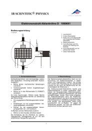
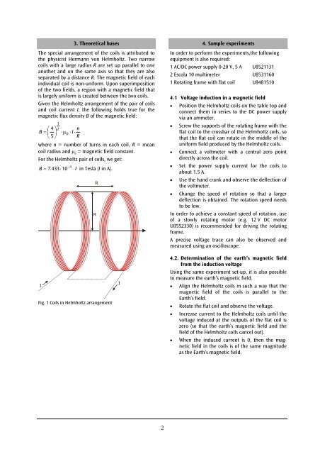
The special arrangement of the coils is attributed to<br />
the physicist Hermann von <strong>Helmholtz</strong>. Two narrow<br />
coils with a large radius R are set up parallel to one<br />
another and on the same axis so that they are also<br />
separated by a distance R. The magnetic field of each<br />
individual coil is non-uniform. Upon superimposition<br />
of the two fields, a region with a magnetic field that<br />
is largely uniform is created between the two coils.<br />
Given the <strong>Helmholtz</strong> arrangement of the pair of coils<br />
and coil current I, the following holds true for the<br />
magnetic flux density B of the magnetic field:<br />
3<br />
2<br />
⎛ 4 ⎞<br />
B = ⎜ ⎟ ⋅µ 0<br />
⎝ 5 ⎠<br />
n<br />
⋅I<br />
⋅<br />
R<br />
where n = number of turns in each coil, R = mean<br />
coil radius and µ 0<br />
= magnetic field constant.<br />
For the <strong>Helmholtz</strong> pair of coils, we get:<br />
−4<br />
B = 7 . 433⋅<br />
10 ⋅I<br />
in Tesla (I in A).<br />
Fig. 1 Coils in <strong>Helmholtz</strong> arrangement<br />
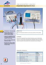
4. Sample experiments<br />
In order to perform the experiments,the following<br />
equipment is also required:<br />
1 AC/DC power supply 0-20 V, 5 A U8521131<br />
2 Escola 10 multimeter U8531160<br />
1 Rotating frame with flat coil U8481510<br />
4.1 Voltage induction in a magnetic field<br />
• Position the <strong>Helmholtz</strong> coils on the table top and<br />
connect them in series to the DC power supply<br />
via an ammeter.<br />
• Screw the supports of the rotating frame with the<br />
flat coil to the crossbar of the <strong>Helmholtz</strong> coils, so<br />
that the flat coil can rotate in the middle of the<br />
uniform field produced by the <strong>Helmholtz</strong> coils.<br />
• Connect a voltmeter with a central zero point<br />
directly across the coil.<br />
• Set the power supply current for the coils to<br />
about 1.5 A.<br />
• Use the hand crank and observe the deflection of<br />
the voltmeter.<br />
• Change the speed of rotation so that a larger<br />
deflection is obtained. The rotation speed needs<br />
to be low.<br />
In order to achieve a constant speed of rotation, use<br />
of a slowly rotating motor (e.g. 12 V DC motor<br />
U8552330) is recommended for driving the rotating<br />
frame.<br />
A precise voltage trace can also be observed and<br />
measured using an oscilloscope.<br />
4.2. Determination of the earth’s magnetic field<br />
from the induction voltage<br />
Using the same experiment set-up, it is also possible<br />
to measure the earth’s magnetic field.<br />
• Align the <strong>Helmholtz</strong> coils in such a way that the<br />
magnetic field of the coils is parallel to the<br />
Earth’s field.<br />
• Rotate the flat coil and observe the voltage.<br />
• Increase current to the <strong>Helmholtz</strong> coils until the<br />
voltage induced at the outputs of the flat coil is<br />
zero (so that the earth’s magnetic field and the<br />
field of the <strong>Helmholtz</strong> coils cancel out).<br />
• When the induced current is 0, then the magnetic<br />
field in the coils is of the same magnitude<br />
as the Earth’s magnetic field.<br />
2