3B SCIENTIFIC® PHYSICS - American 3B Scientific
3B SCIENTIFIC® PHYSICS - American 3B Scientific
3B SCIENTIFIC® PHYSICS - American 3B Scientific

You also want an ePaper? Increase the reach of your titles
YUMPU automatically turns print PDFs into web optimized ePapers that Google loves.
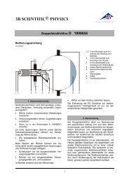
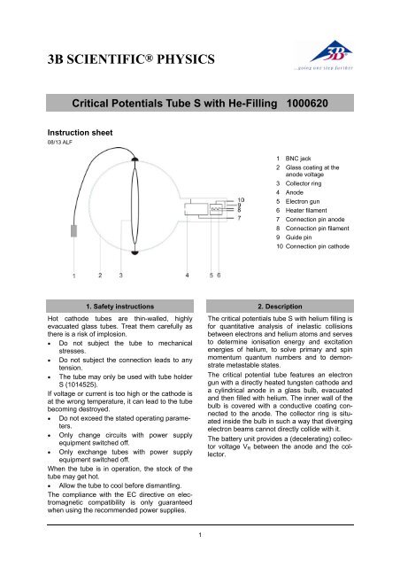
<strong>3B</strong> <strong>SCIENTIFIC®</strong> <strong>PHYSICS</strong>Critical Potentials Tube S with He-Filling 1000620Instruction sheet08/13 ALF1 BNC jack2 Glass coating at theanode voltage3 Collector ring4 Anode5 Electron gun6 Heater filament7 Connection pin anode8 Connection pin filament9 Guide pin10 Connection pin cathode1. Safety instructionsHot cathode tubes are thin-walled, highlyevacuated glass tubes. Treat them carefully asthere is a risk of implosion.• Do not subject the tube to mechanicalstresses.• Do not subject the connection leads to anytension.• The tube may only be used with tube holderS (1014525).If voltage or current is too high or the cathode isat the wrong temperature, it can lead to the tubebecoming destroyed.• Do not exceed the stated operating parameters.• Only change circuits with power supplyequipment switched off.• Only exchange tubes with power supplyequipment switched off.When the tube is in operation, the stock of thetube may get hot.• Allow the tube to cool before dismantling.The compliance with the EC directive on electromagneticcompatibility is only guaranteedwhen using the recommended power supplies.2. DescriptionThe critical potentials tube S with helium filling isfor quantitative analysis of inelastic collisionsbetween electrons and helium atoms and servesto determine ionisation energy and excitationenergies of helium, to solve primary and spinmomentum quantum numbers and to demonstratemetastable states.The critical potential tube features an electrongun with a directly heated tungsten cathode anda cylindrical anode in a glass bulb, evacuatedand then filled with helium. The inner wall of thebulb is covered with a conductive coating connectedto the anode. The collector ring is situatedinside the bulb in such a way that divergingelectron beams cannot directly collide with it.The battery unit provides a (decelerating) collectorvoltage V R between the anode and the collector.1
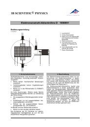
3. Contents1 Critical potentials tube S with He filling1 Battery unit (battery not included)1 Shielding1 ManualTake note of the unique position of the guidepin.6.2 Removing the tube from the tube holder• Allow the tube to cool before dismantling.• To remove the tube, apply pressure on theguide pin until the pins loosen, then pull outthe tube.Gas filling:Filament voltage:Anode voltage:Anode current:Collector voltage:Collector current:Glass bulb:Length of tube:4. Technical dataHeliumU F ≤ 7 V DCU A ≤ 60 VI A ≤ 10 mAU R = 1,5 VI R ≤ 200 pA130 mm diam. approx260 mm approx.5. Additionally requiredFor operating the tube:1 Tube holder S 10145251 Control Unit for Critical Potential Tubes(115 V or 230 V) 1000633 / 10085061 DC-Power Supply, 0–20 V(115 V or 230 V) 1003311 / 1003312or1 Power Supply Unit for Franck-Hertz Experiment(115 V or 230 V) 1012819 / 1012818For making measurements:1 Analogue Oscilloscope 2x30 MHz 10027272 HF Patch Cords, BNC/4 mm Plug 1002748or1 <strong>3B</strong> NETlog TM(115 V or 230 V) 1000539 / 10005401 <strong>3B</strong> NETlab TM 10005441 Battery AA 1.5 V1 Set of 15 Safety Experiment Leads 10028436. Operation6.1 Setting up the tube in the tube holder• The tube should not be mounted or removedunless all power supplies are disconnected.• Press tube gently into the stock of the holderand push until the pins are fully inserted.7. Example experimentDetermine the critical potentials of a heliumatom7.1 General notesThe experiment set-up with the critical potentialtube is highly sensitive to sources of electromagneticinterference. (computers, fluorescentlights).• Select a location for the experiment whereelectromagnetic interference can beavoided.7.2 Experiment set-up with the control unitfor critical potential tubes• Insert the tube into the tube holder.Provision of heater voltage V F :• Connect the sockets F3 of the tube holder tothe positive terminal of the DC power supplyand F4 to the negative terminal. (see Fig. 1)Provision of accelerating voltage V A :• Connect socket C5 of the tube holder to thenegative terminal of the output V A on thecontrol unit and to the negative terminal ofthe DC power supply.• Connect socket A1 to the positive terminal ofthe output V A on the control unit.Provision of collector voltage V R :• The positive pole of the output V A should beconnected to the negative pole of the 1.5-Vbattery.• Connect the positive terminal of the 1.5 Vbattery to an earth socket on the control unit.• Put the shielding over the tube and slot it intothe groove on the tube holder so that the tubeis completely enclosed by shielding. Thenconnect the control unit by means of theground socket.• Connect the lead from the collector ring tothe BNC input socket of the control unit.2
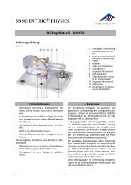
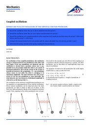
C5F4F3A1Battery Unit- ++160V AOUT3200 mV!4HERTZ TUBE CONSOLEMAXSET V AMIN340...±1 VOLT OUT 0...±1 VOLT OUTSLOW21 SLOW 2 1 FAST 2 RUNRINGFig. 1 Experiment set-up with the control unit for critical potential tubes7.2.1 Procedure with <strong>3B</strong> NETlog TM• At the output V A of the control unit, set theminimum voltage to about 10 V and themaximum voltage to about 35 V, by usingthe <strong>3B</strong> NETlog unit to measure thevoltages (smaller by a factor of 1000)between socket 3 and earth and thatbetween socket 4 and earth. Alternatively,the voltages can be set up with the help of amultimeter.• Connect the <strong>3B</strong> NETlog unit to thecomputer.• Connect the output “Fast 1” from the controlunit to input A of the <strong>3B</strong> NETlog unit andthe output “Fast 2” to input B. (See Fig. 2)• Switch on the <strong>3B</strong> NETlog unit and start the<strong>3B</strong> NETlab program on the computer.• Select the “Measurement lab” function andopen a new data record.• Select analogue inputs A and B and DCvoltage mode (VDC), setting themeasurement ranges to 200 mV for A and2 V for B.• Enter the formula I = -667 * “Input_B“ (unitpA).• Set the following parameters: Measurementinterval = 50 µs, Measurement duration =0.05 s, Mode = Recorder.• Set triggering on the input A with rising edge(20%).• On the DC power supply, set the heatervoltage to 3.5 V.• Start the graph-plotting of the experimentaldata.• Set up the graph with “relative time t in s” onthe x-axis and the quantity I on the y-axis.• Repeat the measurements with slightlyhigher heater voltages and vary theminimum and maximum acceleratingvoltages U A to find the optimum graph.• In the spectrum, identify the 2 3 S peak at19.8 eV and determine its position t 1 on thetime axis.• Identify the ionisation threshold at 24.6 eVand determine its position t 2 on the timeaxis.• Enter a new formula for the quantity Edefined as 19.8 + 4.8 * (t - t 1 )/( t 2 - t 1 ) withthe unit eV; in this expression enter the3
numerical values for t 1 and t 2 in sdetermined as above.• Set up a graph with the quantity E on the x-axis and the quantity I on the y-axis. (SeeFig. 3).• In order to display the ionisation curve,reverse the polarity of the collector voltage.+160V AOUT3200 mV!4HERTZ TUBE CONSOLEMAXSET V AMIN34ChannelRateStoreOn/OffDate/Time0...±1 VOLT OUT 0...±1 VOLT OUTSLOW21 SLOW 2 1 FAST 2 RUNRINGI in A+UAoutUA+inUBoutUB+inFig. 2 Connection of <strong>3B</strong> NETlog TM to the control unit for critical potential tubesFig. 3: Determination of critical potentials for helium atoms (curve recorded using <strong>3B</strong> NETlog TM )7.2.2 Procedure with an oscilloscope• Connect output Fast1 on the control unit toChannel 1 (X deflection) on the oscilloscopeand output Fast 2 to Channel 2 (Y deflection).(See Fig. 4)• Set the minimum voltage output V A on thecontrol unit to approximately 10 V and themaximum voltage to about 35 V. Use a multimeterto measure the voltage betweensocket 3 and ground or socket 4 andground, which will be a factor of 1000 timessmaller.• On the DC power supply, set the heatervoltage to 3.5 V.Oscilloscope settings:Channel 1: 50 mV/divChannel 2: 0.2 V/divTime-base: 5 msTrigger on Channel 1• Vary the heating voltage, the upper and lowerlimits of the accelerating voltage and the oscilloscopeparameters until the best curve canbe seen.• In order to display the ionisation curve, reversethe polarity of the collector voltage.• Zur Aufzeichnung der Ionisationskurve diePolarität der Kollektorspannung vertauschen.4
OSCILLOSCOPE+160V AOUT!3200 mV4MAX3HERTZ TUBE CONSOLESET V AMIN40...±1 VOLT OUT 0...±1 VOLT OUTSLOW21 SLOW 2 1 FAST 2 RUNRINGCH1(X)CH2(Y)EXTFig. 4 Connection of an oscilloscope to the control unit for critical potential tubes7.3 Experiment set-up with the control unitfor the Franck-Hertz experiment• Insert the tube into the tube holder.Provision of heater voltage V F :• Connect socket F3 on the tube holder tosocket F on the control unit for the Franck-Hertz experiment and connect socket F4 tosocket K. (refer to Fig. 5)Provision of accelerating voltage V A :• Connect socket C5 on the tube holder tosocket K on the control unit and socket A1 tosocket A.The provision of collector voltage V R is handledinternally inside the control unit for the Franck-Hertz experiment.• Put the shielding over the tube and slot it intothe groove on the tube holder so that the tubeis completely enclosed by shielding. Thenconnect the control unit by means of theground socket.• Connect the collector ring to the BNC inputon the control unit.BETRIEBSGERÄT FRANCK-HERTZ/OPERATING UNIT FRANCK-HERTZC5F4F3A1FHeizungFilamentU FVGitter/Grid0 12U GVBeschleunigung/AccelerationEReverse bias0 0 080 80 12U AminU AmaxU EVVVMan/Ramp +/-VKGA110Ux= UA+ 1 10UY= IE*VFig. 5 Experiment set-up with the control unit for the Franck-Hertz experiment7.3.1 Procedure with <strong>3B</strong> NETlog TM• Connect the <strong>3B</strong> NETlog TM unit to the controlunit for the Franck-Hertz experiment (seeFig. 6). Connect the Ux output of the controlunit to input A of the <strong>3B</strong> NETlog TM unit andoutput Uy to input B.• Set the control unit to ramp mode and configurea minimum voltage of about 10 V, witha maximum voltage of about 35 V.• Select a heater voltage of some 3.5 V and acollector voltage of around -1.5 V.• Set up the <strong>3B</strong> NETlog TM interface, the<strong>3B</strong> NETlab TM computer program and themeasurement recording as described in section7.2.1.• Vary the heating voltage, the upper and lowerlimits of the accelerating voltage and the gainuntil the best optimal can be seen.• In order to display the ionisation curve, reversethe polarity of the collector voltage.7.3.2 Procedure with an oscilloscope• Connect the Ux output of the control unit toChannel 1 (X deflection) of the oscilloscopeand output Uy to Channel 2 (Y deflection)(see Fig. 7).5
Fig.8 Example curve recorded with the control unit for the Franck-Hertz experiment7.3.3 Calibration of measurement curve• Set the heater voltage to 3.5 V and collectorvoltage to -1.5 V; set the lower limit for theaccelerating voltage to 0 V and the upperlimit to 60 V. Turn up the gain.The oscilloscope screen shows a curve which hasa weakly defined structure in three places. The firstof these structures are of interest here. To emphasisethese places, carry out the following procedure.• Reduce the upper limit of the acceleratingvoltage down to about 35 V.This zooms in on the measurement curve andthe structures become clearer.• In order to display the curve even bigger,raise either the gain or the heater voltage.You may need to change the oscilloscopesettings.• Raise the upper limit of the acceleratingvoltage (to about 15 V) until the curve startsat the edge of the first peak. You may needto increase the gain to display the structuresbetter.• Reduce the upper limit of the acceleratingvoltage (to about 20 V) until the curve endsat the point where ionisation begins.The range of the curve in which the critical potentialslie is now displayed within clearly definedlimits on the oscilloscope screen and thecritical potentials themselves can specifically beidentified.A TELTRON Product from UK<strong>3B</strong> <strong>Scientific</strong> Ltd. ▪ Suite 1 Formal House, Oldmixon Crescent ▪ Weston-super-MareSomerset BS24 9AY ▪ Tel 0044 (0)1934 425333 ▪ Fax 0044 (0)1934 425334 ▪ e-mail uk3bs@3bscientific.comTechnical amendments are possible© Copyright 2013 <strong>3B</strong> <strong>Scientific</strong> GmbH