3B SCIENTIFIC® PHYSICS - American 3B Scientific
3B SCIENTIFIC® PHYSICS - American 3B Scientific
3B SCIENTIFIC® PHYSICS - American 3B Scientific

You also want an ePaper? Increase the reach of your titles
YUMPU automatically turns print PDFs into web optimized ePapers that Google loves.
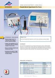
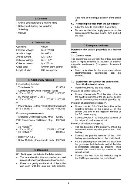
3. Contents1 Critical potentials tube S with He filling1 Battery unit (battery not included)1 Shielding1 ManualTake note of the unique position of the guidepin.6.2 Removing the tube from the tube holder• Allow the tube to cool before dismantling.• To remove the tube, apply pressure on theguide pin until the pins loosen, then pull outthe tube.Gas filling:Filament voltage:Anode voltage:Anode current:Collector voltage:Collector current:Glass bulb:Length of tube:4. Technical dataHeliumU F ≤ 7 V DCU A ≤ 60 VI A ≤ 10 mAU R = 1,5 VI R ≤ 200 pA130 mm diam. approx260 mm approx.5. Additionally requiredFor operating the tube:1 Tube holder S 10145251 Control Unit for Critical Potential Tubes(115 V or 230 V) 1000633 / 10085061 DC-Power Supply, 0–20 V(115 V or 230 V) 1003311 / 1003312or1 Power Supply Unit for Franck-Hertz Experiment(115 V or 230 V) 1012819 / 1012818For making measurements:1 Analogue Oscilloscope 2x30 MHz 10027272 HF Patch Cords, BNC/4 mm Plug 1002748or1 <strong>3B</strong> NETlog TM(115 V or 230 V) 1000539 / 10005401 <strong>3B</strong> NETlab TM 10005441 Battery AA 1.5 V1 Set of 15 Safety Experiment Leads 10028436. Operation6.1 Setting up the tube in the tube holder• The tube should not be mounted or removedunless all power supplies are disconnected.• Press tube gently into the stock of the holderand push until the pins are fully inserted.7. Example experimentDetermine the critical potentials of a heliumatom7.1 General notesThe experiment set-up with the critical potentialtube is highly sensitive to sources of electromagneticinterference. (computers, fluorescentlights).• Select a location for the experiment whereelectromagnetic interference can beavoided.7.2 Experiment set-up with the control unitfor critical potential tubes• Insert the tube into the tube holder.Provision of heater voltage V F :• Connect the sockets F3 of the tube holder tothe positive terminal of the DC power supplyand F4 to the negative terminal. (see Fig. 1)Provision of accelerating voltage V A :• Connect socket C5 of the tube holder to thenegative terminal of the output V A on thecontrol unit and to the negative terminal ofthe DC power supply.• Connect socket A1 to the positive terminal ofthe output V A on the control unit.Provision of collector voltage V R :• The positive pole of the output V A should beconnected to the negative pole of the 1.5-Vbattery.• Connect the positive terminal of the 1.5 Vbattery to an earth socket on the control unit.• Put the shielding over the tube and slot it intothe groove on the tube holder so that the tubeis completely enclosed by shielding. Thenconnect the control unit by means of theground socket.• Connect the lead from the collector ring tothe BNC input socket of the control unit.2