3B SCIENTIFIC® PHYSICS - American 3B Scientific
3B SCIENTIFIC® PHYSICS - American 3B Scientific
3B SCIENTIFIC® PHYSICS - American 3B Scientific

You also want an ePaper? Increase the reach of your titles
YUMPU automatically turns print PDFs into web optimized ePapers that Google loves.
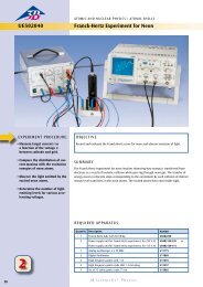
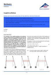
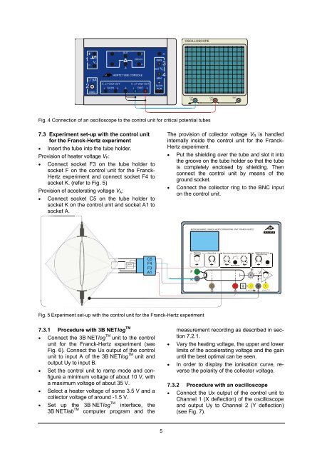
OSCILLOSCOPE+160V AOUT!3200 mV4MAX3HERTZ TUBE CONSOLESET V AMIN40...±1 VOLT OUT 0...±1 VOLT OUTSLOW21 SLOW 2 1 FAST 2 RUNRINGCH1(X)CH2(Y)EXTFig. 4 Connection of an oscilloscope to the control unit for critical potential tubes7.3 Experiment set-up with the control unitfor the Franck-Hertz experiment• Insert the tube into the tube holder.Provision of heater voltage V F :• Connect socket F3 on the tube holder tosocket F on the control unit for the Franck-Hertz experiment and connect socket F4 tosocket K. (refer to Fig. 5)Provision of accelerating voltage V A :• Connect socket C5 on the tube holder tosocket K on the control unit and socket A1 tosocket A.The provision of collector voltage V R is handledinternally inside the control unit for the Franck-Hertz experiment.• Put the shielding over the tube and slot it intothe groove on the tube holder so that the tubeis completely enclosed by shielding. Thenconnect the control unit by means of theground socket.• Connect the collector ring to the BNC inputon the control unit.BETRIEBSGERÄT FRANCK-HERTZ/OPERATING UNIT FRANCK-HERTZC5F4F3A1FHeizungFilamentU FVGitter/Grid0 12U GVBeschleunigung/AccelerationEReverse bias0 0 080 80 12U AminU AmaxU EVVVMan/Ramp +/-VKGA110Ux= UA+ 1 10UY= IE*VFig. 5 Experiment set-up with the control unit for the Franck-Hertz experiment7.3.1 Procedure with <strong>3B</strong> NETlog TM• Connect the <strong>3B</strong> NETlog TM unit to the controlunit for the Franck-Hertz experiment (seeFig. 6). Connect the Ux output of the controlunit to input A of the <strong>3B</strong> NETlog TM unit andoutput Uy to input B.• Set the control unit to ramp mode and configurea minimum voltage of about 10 V, witha maximum voltage of about 35 V.• Select a heater voltage of some 3.5 V and acollector voltage of around -1.5 V.• Set up the <strong>3B</strong> NETlog TM interface, the<strong>3B</strong> NETlab TM computer program and themeasurement recording as described in section7.2.1.• Vary the heating voltage, the upper and lowerlimits of the accelerating voltage and the gainuntil the best optimal can be seen.• In order to display the ionisation curve, reversethe polarity of the collector voltage.7.3.2 Procedure with an oscilloscope• Connect the Ux output of the control unit toChannel 1 (X deflection) of the oscilloscopeand output Uy to Channel 2 (Y deflection)(see Fig. 7).5