
Create successful ePaper yourself
Turn your PDF publications into a flip-book with our unique Google optimized e-Paper software.
2 096 949-Ed.01 / 2008-07-Kothes!<br />
<strong>Wilo</strong>-<strong>Control</strong> <strong>DigiCon</strong>/<strong>DigiCon</strong>-A<br />
D Einbau- und Betriebsanleitung<br />
GB Installation and operating instructions<br />
F Notice de montage et de mise en service<br />
I Istruzioni di montaggio, uso e manutenzione<br />
E Instrucciones de instalación y funcionamiento
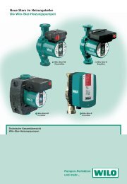
Fig. 1<br />
1<br />
6<br />
19<br />
<strong>DigiCon</strong><br />
24 VDC<br />
-<br />
pump 1 pump 2 pump 3 pump 4<br />
address<br />
+<br />
power<br />
rs 485<br />
1<br />
ON<br />
2<br />
3<br />
4<br />
RSN<br />
5<br />
rs 485<br />
6<br />
1<br />
0/0/0<br />
1<br />
mode<br />
p-c<br />
p-v<br />
n-c<br />
a b Z Baud<br />
21 20<br />
0/0/0<br />
2 3 4<br />
2<br />
set point<br />
100%<br />
0%<br />
0/0/0<br />
3<br />
rs 232<br />
0/0/0<br />
4<br />
2<br />
16<br />
14<br />
15<br />
22
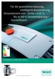
Fig. 2<br />
1<br />
4<br />
<strong>DigiCon</strong>-A<br />
-<br />
+<br />
0-10V off max min on 24V ssm ebm-ma ebm-sl<br />
ma<br />
0-10V off max min on 24V ssm ebm-ma ebm-sl<br />
-<br />
18<br />
+<br />
10<br />
11 12 13 7 8 9<br />
1 1 1<br />
sl<br />
ma sl<br />
2 2 2<br />
18 10 11 12 13 7 8 9<br />
0-10V<br />
disable<br />
0-10V<br />
disable<br />
5<br />
17<br />
3<br />
22
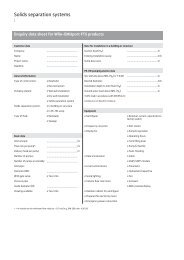
Fig. 3<br />
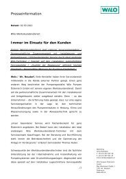
Fig. 4<br />
n-c<br />
p-c<br />
p-v<br />
[min [m] -1 ]<br />
nmax<br />
Hmax<br />
nmin Hmin<br />
0 % 100 % set point<br />
0 V 10 V 0-10 V<br />
1 2 3 4<br />
pump 1 pump 2 pump 3 pump 4<br />
pump 1 pump 3<br />
<strong>DigiCon</strong> <strong>DigiCon</strong>-A<br />
<strong>DigiCon</strong>-A<br />
1 2 3 4<br />
1 2 3 4<br />
pump 2 pump 4<br />
1 2 3 4
Fig. 5<br />
RS 485<br />
Fig. 6a<br />
+<br />
24V DC<br />
-<br />
pump 1 pump 2 pump 3 pump 4<br />
- +<br />
a b<br />
rs 485<br />
<strong>DigiCon</strong> Nr. 1<br />
pump 1 pump 2 pump 3 pump 4<br />
- +<br />
a b<br />
rs 485<br />
<strong>DigiCon</strong> Nr. 2<br />
max. 1000 m<br />
1<br />
pump 1 pump 2 pump 3 pump 4<br />
- +<br />
a b<br />
<strong>DigiCon</strong> Nr. 64<br />
rs 485
Fig. 6b<br />
1<br />
6<br />
19<br />
<strong>DigiCon</strong><br />
24 VDC<br />
Fig. 6c<br />
-<br />
power<br />
pump 1 pump 2 pump 3 pump 4<br />
rs 485<br />
address<br />
ON<br />
RSN<br />
1 2 3 4 5 6<br />
+<br />
rs 485<br />
1<br />
0/0/0<br />
1<br />
2 3 4<br />
0/0/0 0/0/0 0/0/0<br />
2<br />
3<br />
4<br />
mode<br />
set point<br />
p-c<br />
p-v<br />
100%<br />
n-c<br />
0%<br />
a b Z Baud<br />
21 20<br />
rs 232<br />
1 2<br />
1 2<br />
2<br />
16<br />
14<br />
15<br />
22
D Einbau- und Betriebsanleitung 3<br />
GB Installation and operating instructions 21<br />
F Notice de montage et de mise en service 40<br />
I Istruzioni di montaggio, uso e manutenzione 61<br />
E Instrucciones de instalación y funcionamiento 81
Einbau- 1 und Allgemeines Betriebsanleitung<br />
1.1 Über dieses Dokument<br />
Die Einbau- und Betriebsanleitung ist Bestandteil des Produktes. Sie ist jederzeit<br />
in Produktnähe bereitzustellen. Das genaue Beachten dieser Anweisung ist<br />
Voraussetzung für den bestimmungsgemäßen Gebrauch und die richtige Bedienung<br />
des Produktes.<br />
Die Einbau- und Betriebsanleitung entspricht der Ausführung des Produktes<br />
und dem Stand der zugrunde gelegten sicherheitstechnischen Normen bei<br />
Drucklegung.<br />
Diese Einbau- und Betriebsanleitung ist als Ergänzung zur Einbau- und<br />
Betriebsanleitung der an die Schnittstellen-Konverter angeschlossenen<br />
Pumpen zu betrachten.<br />
2 Sicherheit<br />
Diese Betriebsanleitung enthält grundlegende Hinweise, die bei Aufstellung und<br />
Betrieb zu beachten sind. Daher ist diese Betriebsanleitung unbedingt vor Montage<br />
und Inbetriebnahme vom Monteur sowie dem zuständigen Betreiber zu<br />
lesen.<br />
Es sind nicht nur die unter diesem Hauptpunkt Sicherheit aufgeführten allgemeinen<br />
Sicherheitshinweise zu beachten, sondern auch die unter den folgenden<br />
Hauptpunkten mit Gefahrensymbolen eingefügten, speziellen Sicherheitshinweise.<br />
2.1 Kennzeichnung von Hinweisen in der Betriebsanleitung<br />
Symbole:<br />
Allgemeines Gefahrensymbol<br />
Gefahr durch elektrische Spannung<br />
HINWEIS: ...<br />
Signalwörter:<br />
GEFAHR!<br />
Akut gefährliche Situation.<br />
Nichtbeachtung führt zu Tod oder schwersten Verletzungen.<br />
WARNUNG!<br />
Der Benutzer kann (schwere) Verletzungen erleiden. 'Warnung' beinhaltet,<br />
dass (schwere) Personenschäden wahrscheinlich sind, wenn der Hinweis<br />
missachtet wird.<br />
Deutsch<br />
Einbau- und Betriebsanleitung <strong>Wilo</strong>-<strong>Control</strong> <strong>DigiCon</strong>/<strong>DigiCon</strong>-A 3
Deutsch<br />
VORSICHT!<br />
Es besteht die Gefahr, die Pumpe/Anlage zu beschädigen. 'Vorsicht' bezieht<br />
sich auf mögliche Produktschäden durch Missachten des Hinweises.<br />
HINWEIS:<br />
Ein nützlicher Hinweis zur Handhabung des Produktes. Er macht auch auf mögliche<br />
Schwierigkeiten aufmerksam.<br />
2.2 Sicherheitshinweise für Inspektions- und Montagearbeiten<br />
Bei allen Arbeiten an den Schnittstellen-Konvertern und Pumpe(n)/Anlage<br />
sind die Sicherheitshinweise der Betriebsanleitungen der Pumpe(n) zu<br />
beachten.<br />
Gefahr durch Stromschlag<br />
Gefährdungen durch elektrische Energie sind auszuschließen.<br />
Arbeiten an Pumpe(n)/Anlage dürfen nur bei mechanischem Stillstand, in<br />
spannungslosem Zustand und mit geeigneten Werkzeugen ausgeführt werden.<br />
3 Transport und Zwischenlagerung<br />
Bei Erhalt Produkt sofort auf Transportschäden überprüfen. Bei Feststellung von<br />
Transportschäden sind die notwendigen Schritte innerhalb der entsprechenden<br />
Fristen beim Spediteur einzuleiten.<br />
VORSICHT! Beschädigungsgefahr für den Schnittstellen-Konverter<br />
Gefahr der Beschädigung durch unsachgemäße Handhabung bei Transport<br />
und Lagerung.<br />
• Die Schnittstellen-Konverter <strong>DigiCon</strong>/<strong>DigiCon</strong>-A sind bei Transport und<br />
Zwischenlagerung gegen Feuchtigkeit, Frost und mechanische Beschädigung<br />
zu schützen.<br />
• Sie dürfen keinen Temperaturen außerhalb des Bereiches von - 10°C bis<br />
+ 70°C ausgesetzt werden.<br />
4 WILO AG 07/2008
4 Verwendungszweck<br />
<strong>Wilo</strong>-<strong>Control</strong> <strong>DigiCon</strong> <strong>Wilo</strong>-<strong>Control</strong> <strong>DigiCon</strong>-A<br />
Der Schnittstellen-Konverter <strong>DigiCon</strong> wird<br />
für den universellen Anschluss kommunikationsfähiger<br />
Pumpen mit der Schnittstelle<br />
PLR an bauseitige Steuerungs- und<br />
Überwachungseinheiten mit digitaler serieller<br />
Schnittstelle RS 485 benutzt. An eine<br />
serielle Schnittstelle RS 485 lassen sich insgesamt<br />
64 digitale Schnittstellen-Konverter<br />
anschließen.<br />
Anschließbare Pumpen:<br />
• 4 Pumpen (Einzel- oder Doppelpumpen)<br />
Tab. 1<br />
Anschließbare Pumpentypen<br />
Nassläufer-Pumpen<br />
• <strong>Wilo</strong>-TOP-E mit IF-Modul PLR<br />
• <strong>Wilo</strong>-TOP-ED mit 2x IF-Modul PLR<br />
• <strong>Wilo</strong>-Stratos mit IF-Modul Stratos PLR<br />
• <strong>Wilo</strong>-Stratos-D mit 2x IF-Modul Stratos PLR<br />
• <strong>Wilo</strong>-Stratos-Z mit IF-Modul Stratos PLR<br />
Trockenläufer-Pumpen<br />
• <strong>Wilo</strong>-VeroLine-IP-E mit IF-Modul PLR<br />
• <strong>Wilo</strong>-VeroTwin-DP-E mit IF-Modul PLR<br />
• <strong>Wilo</strong>-CronoLine-IL-E mit IF-Modul PLR<br />
• <strong>Wilo</strong>-CronoTwin-DL-E mit 2x IF-Modul PLR<br />
Tab. 2<br />
5 Angaben über das Erzeugnis<br />
5.1 Typenschlüssel<br />
Beispiel: <strong>Wilo</strong>-<strong>Control</strong> <strong>DigiCon</strong><br />
<strong>Control</strong> Baureihenbezeichnung<br />
<strong>DigiCon</strong> Typenbezeichnung: <strong>DigiCon</strong><br />
<strong>DigiCon</strong>-A<br />
Die Erweiterung <strong>DigiCon</strong>-A mit zusätzlicher<br />
Handbedienebene ermöglicht die<br />
übergeordnete Steuerung von Pumpen, die<br />
an Schnittstellen-Konverter <strong>DigiCon</strong> und<br />
<strong>DigiCon</strong>-Modbus angeschlossen sind.<br />
Ansteuerbare Pumpen:<br />
• 2 Pumpen (Einzel- oder Doppelpumpen)<br />
Deutsch<br />
Einbau- und Betriebsanleitung <strong>Wilo</strong>-<strong>Control</strong> <strong>DigiCon</strong>/<strong>DigiCon</strong>-A 5
Deutsch<br />
5.2 Technische Daten <strong>DigiCon</strong> <strong>DigiCon</strong>-A<br />
Versorgungsspannung 24 VDC ± 25% Versorgung erfolgt<br />
über <strong>DigiCon</strong><br />
Stromaufnahme 70 mA (ohne <strong>DigiCon</strong>-A)<br />
140 mA (mit 1x <strong>DigiCon</strong>-A)<br />
210 mA (mit 2x <strong>DigiCon</strong>-A)<br />
Klemmenquerschnitt aller Klemmen 1,5 mm2 Max. Umgebungstemperatur + 50°C<br />
Schutzart nach IEC 60529 IP 20<br />
Rel. Luftfeuchte<br />
Elektromagnetische Verträglichkeit:<br />
Max. 95%, nicht kondensierend<br />
• Störaussendung EN 61000-6-3<br />
• Störfestigkeit<br />
Kontaktbelastung Meldekontakte<br />
EN 61000-6-2<br />
• Sammelstörmeldung<br />
pot.freier Wechsler<br />
• Einzelbetriebsmeldung MA<br />
pot.freier Schließer<br />
• Einzelbetriebsmeldung SL<br />
pot.freier Schließer<br />
Kontaktbelastung durch Steuereingänge<br />
Max.:<br />
250 VAC, 1 A AC-1/<br />
110 VDC, 0,13 A DC-1<br />
Min.:<br />
12 VDC, 10 mA<br />
• „Ext. Off“ pot.freier Schließer 24 VDC, 2,4 mA<br />
• „Regelung ein“ pot.freier Schließer 24 VDC, 2,4 mA<br />
• „Max. Drehzahl“ pot.freier Schließer 24 VDC, 2,4 mA<br />
• „Min. Drehzahl“ pot.freier Schließer 24 VDC, 2,4 mA<br />
Max. Kabellänge je Steuereingang 1000 m<br />
Schleifenwiderstand je Steuereingang<br />
Steuereingang „Analog In 0...10 V“<br />
Max. 480 Ω<br />
• Eingangswiderstand > 200 kΩ<br />
• Überspannungsschutz<br />
Schnittstelle PLR<br />
+/- 48 VDC<br />
• Max. Kabellänge 200 m<br />
• Min. Kabelquerschnitt 2x0,5 mm2 Schnittstelle RS 485<br />
• Max. Kabellänge 1000 m<br />
• Min. Kabelquerschnitt 2x0,5 mm2 (für max.<br />
Leitungslänge)<br />
• Kabeltyp (Beispiel)<br />
Tab. 3<br />
J-Y(St)Y 2x2x0,8<br />
abgeschirmt<br />
6 WILO AG 07/2008
5.3 Lieferumfang<br />
• Schnittstellen-Konverter <strong>DigiCon</strong> oder Handbedienebene <strong>DigiCon</strong>-A<br />
• Einbau- und Betriebsanleitung<br />
• CD mit Dokumentation und Protokolldetails des PLR-Protokolls (nur <strong>DigiCon</strong>)<br />
• 8poliger (2 x 4) Stecker (nur <strong>DigiCon</strong>-A)<br />
6 Beschreibung und Funktion<br />
6.1 Beschreibung der Geräte<br />
<strong>Wilo</strong>-<strong>Control</strong> <strong>DigiCon</strong> <strong>Wilo</strong>-<strong>Control</strong> <strong>DigiCon</strong>-A<br />
Der Schnittstellen-Konverter <strong>DigiCon</strong><br />
wandelt die Schnittstelle PLR (Punkt-zu-<br />
Punkt-Schnittstelle) in eine busfähige,<br />
serielle, digitale Schnittstelle RS 485 um.<br />
Das Software-Protokoll ist PLR. Das Protokoll<br />
ist auf beiliegender CD im Detail<br />
beschrieben und entsprechend umzusetzen.<br />
Anschließbare Pumpen:<br />
• 4 Pumpen (Einzel- oder Doppelpumpen)<br />
Tab. 4<br />
Anschließbare Pumpentypen: Vgl. Tab. 2.<br />
Die Handbedienebene <strong>DigiCon</strong>-A ermöglicht<br />
die übergeordnete Steuerung von<br />
Pumpen, die an Schnittstellen-Konverter<br />
<strong>DigiCon</strong> angeschlossen sind. Steuerbefehle<br />
auf dem Bus zur Pumpe können überschrieben<br />
werden durch:<br />
• Eingänge für potenzialfreie Steuerkontakte<br />
• Analoger Steuereingang 0...10 V<br />
Stör- und Betriebsmeldungen von der<br />
Pumpe werden umgesetzt als:<br />
• Potenzialfreie Meldekontakte und Meldeleuchten<br />
Ansteuerbare Pumpen:<br />
• 2 Pumpen (Einzel- oder Doppelpumpen)<br />
HINWEIS:<br />
• Doppelpumpen sind immer mit dem integrierten Doppelpumpenmanagement<br />
auszurüsten.<br />
• Bei Doppelpumpen wird die Schnittstelle PLR des Masters an den Schnittstellen-Konverter<br />
angeschlossen.<br />
• Wird bei Doppelpumpen das integrierte Doppelpumpenmanagement nicht<br />
benutzt, so sind die beiden Antriebe wie zwei separate Einzelpumpen zu behandeln.<br />
• Steuerfunktionen beziehen sich auf die Doppelpumpe als gesamtes Aggregat.<br />
Deutsch<br />
Einbau- und Betriebsanleitung <strong>Wilo</strong>-<strong>Control</strong> <strong>DigiCon</strong>/<strong>DigiCon</strong>-A 7
Deutsch<br />
6.2 Funktionen und Bedienung der Schnittstellen-Konverter/Handbedienebene<br />
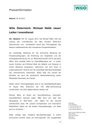
6.2.1 Leuchtmeldungen<br />
Meldeleuchte<br />
„Betriebsbereitschaft<br />
Schnittstellen-Konverter“<br />
Fig. 1, 2, Pos.1<br />
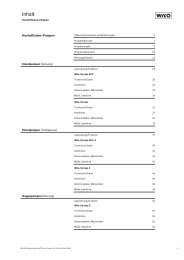
Meldeleuchte<br />
„Kommunikation<br />
Pumpe“<br />
Fig. 1, Pos.2<br />
Meldeleuchte<br />
„Störung Pumpe“<br />
Fig. 2, Pos.3<br />
Meldeleuchte<br />
„Betrieb Einzelpumpe<br />
oder Doppelpumpe<br />
ma“<br />
(ma = Master)<br />
Fig. 2, Pos.4<br />
Meldeleuchte<br />
„Betrieb Doppelpumpe<br />
sl“ (sl = Slave)<br />
Fig. 2, Pos.5<br />
Tab. 5<br />
<strong>DigiCon</strong> <strong>DigiCon</strong>-A<br />
LED leuchtet dauernd grün:<br />
• Versorgungsspannung<br />
24 VDC ist vorhanden.<br />
LED ist aus:<br />
• Versorgungsspannung<br />
24 VDC ist nicht vorhanden.<br />
LED ist aus:<br />
• Pumpe ist nicht angemeldet.<br />
LED leuchtet dauernd grün:<br />
• Kommunikation „Pumpe –<br />
Schnittstellen-Konverter“<br />
arbeitet fehlerfrei.<br />
LED leuchtet dauernd rot:<br />
• Kommunikationsstörung<br />
zwischen Pumpe und<br />
Schnittstellen-Konverter<br />
LED leuchtet dauernd grün:<br />
• Versorgungsspannung über<br />
<strong>DigiCon</strong> ist vorhanden.<br />
LED ist aus:<br />
• Versorgungsspannung über<br />
<strong>DigiCon</strong> ist nicht vorhanden.<br />
LED ist aus:<br />
• Pumpe ist nicht gestört.<br />
LED leuchtet dauernd rot:<br />
• Pumpe ist gestört.<br />
LED ist aus:<br />
• Einzelpumpe oder Doppelpumpe<br />
ma steht still.<br />
LED leuchtet dauernd grün:<br />
• Einzelpumpe oder Doppelpumpe<br />
ma ist in Betrieb.<br />
LED ist aus:<br />
• Doppelpumpe sl steht still.<br />
LED leuchtet dauernd grün:<br />
• Doppelpumpe sl ist in<br />
Betrieb.<br />
8 WILO AG 07/2008
Meldeleuchte<br />
“Kommunikation Bus“<br />
Fig. 1, Pos.6<br />
Tab. 5<br />
6.2.2 Meldekontakte<br />
Sammelstörmeldung „ssm“<br />
potenzialfreier Wechsler<br />
Fig. 2, Pos.7<br />
Einzelbetriebsmeldung Master<br />
„ebm-ma“<br />
potenzialfreier Schließer<br />
Fig. 2, Pos.8<br />
Kontakt wird parallel zur Meldeleuchte<br />
„Betrieb Einzelpumpe oder<br />
Doppelpumpe ma“ angesteuert.<br />
Einzelbetriebsmeldung Slave<br />
„ebm-sl“<br />
potentialfreier Schließer<br />
Fig. 2, Pos.9<br />
Kontakt wird parallel zur Meldeleuchte<br />
„Betrieb Doppelpumpe sl“<br />
angesteuert.<br />
Tab. 6<br />
<strong>DigiCon</strong> <strong>DigiCon</strong>-A<br />
LED ist aus:<br />
- Keine Kommunikation auf<br />
der Schnittstelle RS 485 in der<br />
letzten Minute.<br />
LED leuchtet dauernd grün:<br />
- Kommunikation auf der<br />
Schnittstelle RS 485 innerhalb<br />
der letzten Minute fehlerfrei.<br />
LED leuchtet dauernd rot:<br />
- Kommunikation auf der<br />
Schnittstelle innerhalb der<br />
letzten Minute fehlerhaft.<br />
<strong>DigiCon</strong>-A<br />
Kontakt in Ruhestellung:<br />
• Pumpe ist nicht gestört.<br />
Kontakt aktiviert:<br />
• Pumpe ist gestört, siehe auch Einbau- und<br />
Betriebsanleitung der entsprechenden Pumpe.<br />
Kontakt offen:<br />
• Einzelpumpe oder Doppelpumpe ma steht still.<br />
Kontakt geschlossen:<br />
• Einzelpumpe oder Doppelpumpe ma ist in Betrieb.<br />
Kontakt offen:<br />
• Doppelpumpe sl steht still.<br />
Kontakt geschlossen:<br />
• Doppelpumpe sl ist in Betrieb.<br />
VORSICHT!<br />
Die potenzialfreien Meldekontakte dürfen nur mit einer Betriebsspannungsart<br />
betrieben werden (z.B.: 230 VAC oder 24 VDC).<br />
Deutsch<br />
Einbau- und Betriebsanleitung <strong>Wilo</strong>-<strong>Control</strong> <strong>DigiCon</strong>/<strong>DigiCon</strong>-A 9
Deutsch<br />
6.2.3 Steuereingänge an <strong>DigiCon</strong>-A<br />
Steuerkontakt „off“<br />
potenzialfreier Schließer<br />
Fig. 2, Pos.10<br />
Steuerkontakt „max“<br />
potenzialfreier Schließer<br />
Fig. 2, Pos.11<br />
Steuerkontakt „min“<br />
potenzialfreier Schließer<br />
Fig. 2, Pos.12<br />
Steuerkontakt „on“<br />
potenzialfreier Schließer<br />
Fig. 2, Pos.13<br />
Analogeingang „0-10V“,<br />
Fig. 2, Pos.18<br />
Tab. 7<br />
<strong>DigiCon</strong>-A<br />
Kontakt offen:<br />
• Betrieb der Pumpe wird nicht beeinflusst.<br />
Kontakt geschlossen:<br />
• Pumpe steht still.<br />
Kontakt offen:<br />
• Betrieb der Pumpe wird nicht beeinflusst.<br />
Kontakt geschlossen:<br />
• Pumpe läuft bei max. Drehzahl.<br />
Kontakt offen:<br />
• Betrieb der Pumpe wird nicht beeinflusst.<br />
Kontakt geschlossen:<br />
• Pumpe läuft mit Drehzahl des Nacht-Absenkbetriebs.<br />
Kontakt offen:<br />
• Betrieb der Pumpe wird nicht beeinflusst.<br />
Kontakt geschlossen:<br />
• Pumpe läuft bei vorgewählter Regelungsart und<br />
bei vorgewähltem Sollwert.<br />
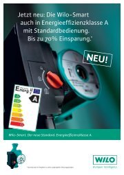
Das Signal am Analogeingang „0-10V“ gibt den<br />
Sollwert für die mit dem Drehschalter „mode“ eingestellte<br />
Regelungsart vor (Fig. 3):<br />
• Δp-c: 0V = Hmin, 10V = Hmax • Δp-v: 0V = Hmin, 10V = Hmax • n-c: 0V = min. Drehzahl, 10V = max. Drehzahl<br />
• Das Signal am Analogeingang „0-10V“ übersteuert<br />
den am Drehknopf „set point“ eingestellten<br />
Wert und den Sollwert, der über den Bus RS 485<br />
gesendet wird.<br />
VORSICHT!<br />
An die Steuereingänge darf keine Fremdspannung angelegt werden.<br />
10 WILO AG 07/2008
6.2.4 Prioritäten der Busbefehle und Steuerkontakte<br />
• Tab. 8 zeigt die Prioritätsreihenfolge der Steuerkontakte und Busbefehle am<br />
<strong>DigiCon</strong>/<strong>DigiCon</strong>-A<br />
Handbedienebene<br />
Busebene RS 485/PLR<br />
Tab. 8<br />
<strong>DigiCon</strong>/<strong>DigiCon</strong>-A<br />
Steuerkontakt „off“ Höchste Priorität<br />
Steuerkontakt „max“<br />
Steuerkontakt „min“<br />
Steuerkontakt „on“<br />
Busbefehl „max“<br />
Busbefehl „min“<br />
Busbefehl „on“ Niedrigste Priorität<br />
Deutsch<br />
Einbau- und Betriebsanleitung <strong>Wilo</strong>-<strong>Control</strong> <strong>DigiCon</strong>/<strong>DigiCon</strong>-A 11
Deutsch<br />
6.2.5 Bedienelemente<br />
Drehschalter „mode“<br />
Fig. 1, Pos.14<br />
Drehknopf „set point“<br />
Fig. 1, Pos.15<br />
Taste<br />
Fig. 1, Pos.16<br />
Tab. 9<br />
<strong>DigiCon</strong> <strong>DigiCon</strong>-A<br />
Drehschalter zur Einstellung<br />
der Regelungsart:<br />
• Δp-c für konstanten Differenzdruck<br />
• Δp-v für variablen Differenzdruck<br />
• n-c für konstante Drehzahl<br />
(Stellerbetrieb)<br />
Einstellung des Sollwertes für<br />
die mit dem Drehschalter<br />
„mode“ vorgewählte Regelungsart<br />
(Fig. 3):<br />
• Δp-c: 0% = Hmin ,<br />
100% = Hmax • Δp-v: 0% = Hmin ,<br />
100% = Hmax • n-c: 0% = min. Drehzahl,<br />
100% = max. Drehzahl<br />
Die Werte Hmin, Hmax, min.<br />
Drehzahl und max. Drehzahl<br />
sind vom Pumpentyp abhängig.<br />
Mit dieser Taste werden die am<br />
Drehschalter „mode“ und am<br />
Drehknopf „set point“ vorgenommenen<br />
Einstellungen an<br />
die entsprechende Pumpe<br />
gesendet. Die Einstellungen<br />
werden nur übernommen,<br />
wenn über den Bus RS 485<br />
keine Befehle an die entsprechende<br />
Pumpe gesendet werden<br />
(falls Pumpe<br />
ausgeschaltet war, wird sie<br />
jetzt eingeschaltet).<br />
12 WILO AG 07/2008
Schalter „set“<br />
Fig. 2, Pos.17<br />
Analogeingang<br />
„0-10V“,<br />
Fig. 2, Pos.18<br />
DIP-Schalterblock<br />
„address“<br />
Fig. 1, Pos.19<br />
DIP-Schalterblock<br />
“Baud“<br />
Fig. 2, Pos.20<br />
DIP-Schalter „Z“<br />
Leitungsimpedanz<br />
120 Ω<br />
Fig. 2, Pos.21<br />
Tab. 9<br />
<strong>DigiCon</strong> <strong>DigiCon</strong>-A<br />
Mit diesem Schalter wird der<br />
Analogeingang „0-10V“ je<br />
Pumpe freigegeben:<br />
• 0-10V: Analogeingang<br />
„0-10V“ freigegeben<br />
• disable: Analogeingang<br />
„0-10V“ gesperrt<br />
Das Signal am Analogeingang<br />
„0-10V“ gibt den Sollwert für<br />
die mit dem Drehschalter<br />
„mode“ eingestellte Regelungsart<br />
vor:<br />
• Δp-c: 0V = Hmin , 10V = Hmax • Δp-v: 0V = Hmin, 10V = Hmax • n-c: 0V = min. Drehzahl,<br />
10V = max. Drehzahl<br />
• Das Signal am Analogeingang<br />
„0-10V“ übersteuert<br />
den am Drehknopf „set<br />
point“ eingestellten Wert<br />
und den Sollwert, der über<br />
den Bus RS 485 gesendet<br />
wird.<br />
An diesem DIP-Schalterblock<br />
wird die Addresse des zugehörigenSchnittstellen-Konverters<br />
eingestellt.<br />
An diesem DIP-Schalterblock<br />
wird die Baudrate der Schnittstelle<br />
RS 485 eingestellt.<br />
An diesen DIP-Schaltern kann<br />
je Leitung ein Abschlusswiderstand<br />
der Schnittstelle RS 485<br />
zugeschaltet werden.<br />
Deutsch<br />
Einbau- und Betriebsanleitung <strong>Wilo</strong>-<strong>Control</strong> <strong>DigiCon</strong>/<strong>DigiCon</strong>-A 13
Deutsch<br />
• Die Baudrate ist binär codiert und wird mit dem DIP-Schalterblock „baud“<br />
(Fig. 6, Pos.2) nach Tab. 10 codiert.<br />
Nr. des DIP-Schalters 1 2 3 4<br />
Baud-Rate<br />
1200 0 0 0 0<br />
2400 1 0 0 0<br />
4800 0 1 0 0<br />
9600 1 1 0 0<br />
19,2 k 0 0 1 0<br />
38,4 k 1 0 1 0<br />
57,6 k 0 1 1 0<br />
76,8 k 1 1 1 0<br />
115,2 k 0 0 0 1<br />
0: DIP-Schalter „off“ 1: DIP-Schalter „on“<br />
Tab. 10<br />
• Die Adresse des <strong>DigiCon</strong> ist binär codiert und wird mit dem DIP-Schalterblock<br />
„address“ (Fig. 2, Pos.19) nach Tab. 11 codiert.<br />
• Die Adresse des entsprechenden Pumpen wird durch Addition der mit „1“ versehenen<br />
Wertigkeiten ermittelt, und durch Addition des Wertes des leitungsgebundenen<br />
Anschlusses an die zughörigen Klemmen. Beispiele:<br />
Adresse von Pumpe 1 an <strong>DigiCon</strong> Nr.1(DIP-Schalter 000000): (0)+0=0<br />
Adresse von Pumpe 4 an <strong>DigiCon</strong> Nr.1(DIP-Schalter 000000): (0)+3=3<br />
Adresse von Pumpe 3 an <strong>DigiCon</strong> Nr.12(DIP-Schalter 001011):<br />
(32+8+4)+2=46<br />
14 WILO AG 07/2008
Nr. des DIP-Schalters<br />
Wertigkeit<br />
1<br />
2 7<br />
(=128)<br />
2<br />
2 6<br />
(=64)<br />
3<br />
2 5<br />
(=32)<br />
4<br />
2 4<br />
(=16)<br />
5<br />
2 3<br />
(=8)<br />
6<br />
2 2<br />
(=4)<br />
Resultierende<br />
Pumpen-<br />
Adresse<br />
Nr. der Pumpe/<br />
Nr. des <strong>DigiCon</strong><br />
Pumpe 1/1<br />
0<br />
Pumpe 2/1<br />
Pumpe 3/1<br />
0 0 0 0 0 0<br />
1<br />
2<br />
Pumpe 4/1 3<br />
... ... ... ... ... ... ... ...<br />
Pumpe 1/12<br />
44<br />
Pumpe 2/12<br />
Pumpe 3/12<br />
0 0 1 0 1 1<br />
45<br />
46<br />
Pumpe 4/12 47<br />
... ... ... ... ... ... ... ...<br />
Pumpe 1/26<br />
100<br />
Pumpe 2/26<br />
Pumpe 3/26<br />
0 1 1 0 0 1<br />
101<br />
102<br />
Pumpe 4/26 103<br />
... ... ... ... ... ... ... ...<br />
Pumpe 1/64<br />
252<br />
Pumpe 2/64<br />
Pumpe 3/64<br />
1 1 1 1 1 1<br />
253<br />
254<br />
Pumpe 4/64 255<br />
0: DIP-Schalter „off“ 1: DIP-Schalter „on“<br />
Tab. 11<br />
6.2.6 Priorität der Sollwertvorgabe<br />
• Tab. 12 zeigt die Prioritätsreihenfolge der Sollwertvorgabe<br />
• Der Sollwert über die Schnittstelle RS 485/PLR überschreibt den am Drehknopf<br />
„set point“ eingestellten Sollwert.<br />
Handbedienebene<br />
<strong>DigiCon</strong>/<strong>DigiCon</strong>-A<br />
Analogeingang „0-10V“ Höchste Priorität<br />
Drehknopf „set point“<br />
Busebene RS 485/PLR<br />
Tab. 12<br />
Sollwert über RS 485/PLR Niedrigste Priorität<br />
Deutsch<br />
Einbau- und Betriebsanleitung <strong>Wilo</strong>-<strong>Control</strong> <strong>DigiCon</strong>/<strong>DigiCon</strong>-A 15
Deutsch<br />
7 Installation und elektrischer Anschluss<br />
Installation und elektrischer Anschluss sind gemäß örtlicher Vorschriften<br />
und nur durch Fachpersonal durchzuführen!<br />
WARNUNG! Gefahr von Personenschäden<br />
Die bestehenden Vorschriften zur Unfallverhütung sind zu beachten.<br />
WARNUNG! Gefahr durch Stromschlag<br />
Gefährdungen durch elektrische Energie sind auszuschließen.<br />
Weisungen lokaler oder genereller Vorschriften [z.B. IEC, VDE usw.] und der<br />
örtlichen Energieversorgungsunternehmen sind zu beachten.<br />
7.1 Installation<br />
• Anlage / Schaltschrank spannungsfrei schalten.<br />
VORSICHT! Beschädigungsgefahr für die Schnittstellen-Konverter<br />
• Der Einbau muss in ein Gehäuse mit einer für den Betrieb ausreichenden IP-<br />
Schutzart erfolgen.<br />
• Die Schnittstellen-Konverter werden auf eine Hutschiene 35 mm (IEC 60715)<br />
aufgeschnappt.<br />
• Spannungsversorgung 24 VDC an den/die Schnittstellen-Konverter <strong>DigiCon</strong><br />
anschließen (Fig. 5).<br />
HINWEIS: Ist im Schaltschrank keine Spannungsversorgung 24 VDC vorhanden,<br />
so muss ein separates Netzteil mit entsprechender Ausgangsspannung im<br />
Schaltschrank installiert werden.<br />
Der Ausgangsstrom des Netzteils hängt von der Anzahl der anzuschließenden<br />
<strong>DigiCon</strong>s/Komponenten ab.<br />
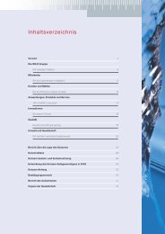
• Die Handbedienebene <strong>DigiCon</strong>-A wird rechts neben dem zugehörigen Schnittstellen-Konverter<br />
<strong>DigiCon</strong> montiert und dann gegen den Schittstellen-Konverter<br />
geschoben, bis die seitlichen Kontakte einrasten. An jeden Schnittstellen-<br />
Konverter <strong>DigiCon</strong> Können zwei Handbedienebenen <strong>DigiCon</strong>-A gekoppelt werden<br />
(Fig. 4).<br />
• Pumpe(n) mit der Schnittstelle PLR an den/die Schnittstellen-Konverter<br />
anschließen (Fig. 5).<br />
HINWEIS: Sind Schnittstellen-Konverter und Pumpe(n) mit Spannung versorgt,<br />
wird automatisch der Datentransfer über die Schnittstelle PLR gestartet.<br />
Sind noch keine aktuellen, pumpenbezogenen Werte an den Schnittstellen-<br />
Konvertern eingestellt, so werden die werksseitig voreingestellten Werte an die<br />
Pumpe(n) gesendet..<br />
• Falls nicht im Schaltschrank vorverdrahtet, Steuer- und Meldekontakte sowie<br />
Analogsignale an den entsprechenden Klemmen auflegen.<br />
• Kennzeichnung der Schnittstellen-Konverter<br />
HINWEIS: Die Schnittstellen-Konverter <strong>DigiCon</strong> und die Handbedienebene Digi-<br />
Con-A besitzen eine Kennzeichnungsfläche (20mm x 10mm, Fig. 1, 2, Pos.22),<br />
in direkt die Bauteilbezeichnung lt. Anlagenschema eingetragen werden kann.<br />
Alternativ kann auf dieser Fläche ein Aufkleber angebracht werden.<br />
16 WILO AG 07/2008
8 Inbetriebnahme<br />
VORSICHT!<br />
Bei der Inbetriebnahme sind die Einbau- und Betriebsanleitungen der an die<br />
Schnittstellen-Konverter angeschlossenen Pumpen zu beachten.<br />
HINWEIS: Die Inbetriebnahme wird stellvertretend für einen <strong>DigiCon</strong> mit<br />
2x<strong>DigiCon</strong>-A und Pumpe(n) beschrieben. Bei Vorhandensein mehrerer <strong>DigiCon</strong>s<br />
ist entsprechend zu verfahren.<br />
• Netzspannung der Pumpe(n) einschalten,<br />
• Versorgungsspannung des <strong>DigiCon</strong> einschalten,<br />
• Die Meldeleuchte(n) „Kommunikation Pumpe“ (Fig. 1, Pos.2) müssen nach ca.<br />
12 s grün aufleuchten. Am Display der Pumpe(n) prüfen, ob der automatische<br />
Verbindungsaufbau zwischen Pumpe(n) und <strong>DigiCon</strong> über die Schnittstelle PLR<br />
erfolgt ist: Im Display der Pumpe(n) muss das Kommunikationssymbol „Doppelpfeil“<br />
zu sehen sein.<br />
Liegt am <strong>DigiCon</strong> kein Signal der Schnittstelle RS 485 an, kann die Einstellung<br />
der Regelungsart und des Sollwertes für jede angeschlossene Pumpe lokal am<br />
<strong>DigiCon</strong> vorgenommen werden:<br />
• Am Schalter „mode“ (Fig. 1, Pos.14) die gewünschte Regelungsart einstellen,<br />
• Am Drehknopf „set point“ (Fig. 1, Pos.15) den gewünschten Sollwert einstellen,<br />
• Durch Drücken der Taste (Fig. 1, Pos.16) werden die Einstellungen an die angeschlossene<br />
Pumpe gesendet. Die vorangegangenen Schritte können für jede an<br />
den <strong>DigiCon</strong> angeschlossene Pumpe mit unterschiedlichen Einstellungen wiederholt<br />
werden.<br />
Werden Regelungsart und Sollwert über die Schnittstelle RS 485 vorgegeben<br />
oder werden Daten von den Pumpe(n) abgefragt, müssen weitere Einstellungen<br />
lokal am <strong>DigiCon</strong> vorgenommen werden:<br />
• Am <strong>DigiCon</strong> die Adresse einstellen gemäß Tab. 11.<br />
• Am <strong>DigiCon</strong> Abdeckleiste der unteren Klemmenreihe mit Schraubendreher<br />
abhebeln und Baudrate einstellen gemäß Tab. 10 (Fig. 6, Pos.1).<br />
• Am <strong>DigiCon</strong>, der am weitesten vom Busübergabepunkt entfernt ist (Fig. 5,<br />
Nr.64), Abdeckleiste der unteren Klemmenreihe mit Schraubendreher abhebeln<br />
und Abschlusswiderstände der Schnittstelle RS 485 einstellen (Fig. 6, Pos.3).<br />
Ist die optionale Handbedienebene <strong>DigiCon</strong>-A installiert, können folgende<br />
Überprüfungen/Einstellungen vorgenommen werden:<br />
• Die Steuereingänge für potenzialfreie Steuerkontakte „off“, „max“, „min“ und<br />
„on“ (Fig. 4, Pos.1, 2, 3, 4) können durch Anlegen einer Drahtbrücke in ihrer<br />
Funktion überprüft werden.<br />
• Falls der Analogeingang „0-10V“ belegt ist, wird er durch den Schalter „set“<br />
(Fig. 2, Pos.17) freigegeben.<br />
Deutsch<br />
Einbau- und Betriebsanleitung <strong>Wilo</strong>-<strong>Control</strong> <strong>DigiCon</strong>/<strong>DigiCon</strong>-A 17
Deutsch<br />
9 Wartung<br />
Wartungs- und Reparaturarbeiten nur durch qualifiziertes Fachpersonal!<br />
WARNUNG! Gefahr durch Stromschlag<br />
Gefahren durch elektrische Energie sind auszuschließen.<br />
Bei allen Wartungs- und Reparaturarbeiten sind die Schnittstellen-Konverter/Pumpe(n)/Anlage<br />
spannungsfrei zu schalten und gegen unbefugtes Wiedereinschalten<br />
zu sichern.<br />
10 Störungen, Ursachen und Beseitigung<br />
Problem Ursachen/zu prüfen Lösung<br />
Eine Pumpe an<br />
einem <strong>DigiCon</strong> folgt<br />
nicht den Vorgaben<br />
der Gebäudeautomation<br />
(GA).<br />
Alle Pumpen an<br />
einem <strong>DigiCon</strong> folgen<br />
nicht den Vorgaben<br />
der Gebäudeautomation<br />
(GA).<br />
Tab. 13<br />
Die GA schickt nicht die richtigen<br />
Vorgaben.<br />
Meldeleuchte “Kommunikation<br />
Bus“ leuchtet konstant<br />
oder ab und zu rot.<br />
Am Display der Pumpe prüfen,<br />
ob der automatische Verbindungsaufbau<br />
zwischen Pumpe<br />
und <strong>DigiCon</strong> über die Schnittstelle<br />
PLR erfolgt ist: Im Display<br />
der Pumpe muss das Kommunikationssymbol„Doppelpfeil“<br />
zu sehen sein.<br />
Die GA schickt nicht die richtigen<br />
Vorgaben.<br />
Meldeleuchte “Kommunikation<br />
Bus“ leuchtet konstant<br />
oder ab und zu rot.<br />
Meldeleuchte „Kommunikation<br />
Pumpe“ leuchtet konstant<br />
rot.<br />
Kabel zwischen GA und Digi-<br />
Con ist unterbrochen.<br />
GA überprüfen, alternativ: PLR-<br />
Anschluss an der Pumpe temporär<br />
abklemmen und Pumpe lokal<br />
einstellen.<br />
RS 485 Kabel: Anschluss,<br />
Abschlusswiderstände und<br />
Kabelschirm überprüfen.<br />
• Kabel zwischen <strong>DigiCon</strong> und<br />
Pumpe ist unterbrochen,<br />
Kabel reparieren.<br />
• IF-Modul überprüfen<br />
GA überprüfen, alternativ: RS<br />
485 am Übergabepunkt temporär<br />
abklemmen und Pumpe(n)<br />
lokal am <strong>DigiCon</strong> steuern.<br />
RS 485 Kabel: Anschluss,<br />
Abschlusswiderstände und<br />
Kabelschirm überprüfen.<br />
• Kabel zwischen Pumpe und<br />
<strong>DigiCon</strong> überprüfen.<br />
• IF-Modul überprüfen.<br />
Kabel reparieren, alternativ<br />
Pumpe(n) lokal am <strong>DigiCon</strong><br />
steuern.<br />
18 WILO AG 07/2008
Problem Ursachen/zu prüfen Lösung<br />
Pumpe läuft nicht<br />
an.<br />
Meldeleuchte<br />
„Kommunikation<br />
Pumpe“ leuchtet rot.<br />
Meldeleuchte<br />
“Kommunikation<br />
Bus“ leuchtet konstant<br />
oder ab und zu<br />
rot.<br />
Tab. 13<br />
„Taste“ (Fig. 1, Pos.16) für<br />
angegebene Pumpe drücken,<br />
wenn sie anläuft war die<br />
Pumpe durch einen Befehl von<br />
der Schnittstelle RS 485 ausgeschaltet.<br />
Überprüfen, ob der Steuerkontakt<br />
„off“ am <strong>DigiCon</strong>-A<br />
geschlossen ist.<br />
Steuerkontakt „on“ überbrücken,<br />
wenn Pumpe jetzt läuft,<br />
sendet GA ständig den Befehl<br />
„Pumpe aus“ über die RS 485.<br />
Überprüfen, ob der Steuerkontakt<br />
„Ext. Off“ an der Pumpe<br />
geöffnet ist.<br />
Fehler an der Verkabelung zwischen<br />
Pumpe und <strong>DigiCon</strong>.<br />
Keine Netzspannunng an der<br />
Pumpe.<br />
Steuerkontakt „off“ am<br />
<strong>DigiCon</strong>-A öffnen.<br />
Pumpe in der GA einschalten.<br />
„Ext Off“ an der Pumpe brücken.<br />
Kabel überprüfen.<br />
Netzspannung wiederherstellen.<br />
Fehler an der Pumpe. Fehler beseitigen.<br />
Kommunikation zwischen<br />
<strong>DigiCon</strong> und Pumpe ist gestört.<br />
Kommunikation zwischen<br />
<strong>DigiCon</strong>(s) und GA ist gestört.<br />
• Kabel überprüfen.<br />
• IF-Modul überprüfen.<br />
• GA überprüfen, alternativ: RS<br />
485 am Übergabepunkt temporär<br />
abklemmen und<br />
Pumpe(n) lokal am <strong>DigiCon</strong><br />
steuern.<br />
• RS 485 Kabel: Anschluss,<br />
Abschlusswiderstände und<br />
Kabelschirm überprüfen.<br />
Lässt sich die Betriebsstörung nicht beheben, wenden Sie sich bitte an das<br />
Fachhandwerk oder an die nächstgelegene <strong>Wilo</strong>-Kundendienststelle oder<br />
Vertretung.<br />
Deutsch<br />
Einbau- und Betriebsanleitung <strong>Wilo</strong>-<strong>Control</strong> <strong>DigiCon</strong>/<strong>DigiCon</strong>-A 19
Deutsch<br />
11 Ersatzteile<br />
Für <strong>Wilo</strong>-<strong>Control</strong> <strong>DigiCon</strong> und <strong>DigiCon</strong>-A sind keine Ersatzteile verfügbar.<br />
Im Schadensfall ist das komplette Gerät zu tauschen und die defekte Einheit an<br />
den Hersteller zurückzugeben.<br />
Technische Änderungen vorbehalten!<br />
20 WILO AG 07/2008
Installation 1 General and operating instructions<br />
1. 1 About this document<br />
These Installation and operating instructions are an integral part of the product.<br />
They must be kept readily available at the place where the product is installed.<br />
Strict adherence to these instructions is a precondition for the proper use and<br />
correct operation of the product.<br />
These Installation and operating instructions correspond to the relevant version<br />
of the product and the underlying safety standards valid at the time of going to<br />
print.<br />
These Installation and Operating instructions should be regarded as an addition<br />
to the installation and operating instructions of the pumps connected to<br />
the interface converter.<br />
2 Safety<br />
These operating instructions contain basic information which must be adhered<br />
to during installation and operation. For this reason, these operating instructions<br />
must, without fail, be read by the service technician and the responsible<br />
operator before installation and commissioning.<br />
It is not only the general safety instructions listed under the main point “safety”<br />
that must be adhered to but also the special safety instructions with danger<br />
symbols included under the following main points.<br />
2. 1 Indication of instructions in the Operating instructions<br />
Symbols<br />
General danger symbol<br />
Danger due to electrical voltage<br />
NOTE: ...<br />
Signal words:<br />
DANGER!<br />
Acutely dangerous situation.<br />
Non-observance results in death or the most serious of injuries.<br />
WARNING!<br />
The user can suffer (serious) injuries. 'Warning' implies that (serious) injury<br />
to persons is probable if this information is disregarded.<br />
English<br />
Installation and operating instructions <strong>Wilo</strong>-<strong>Control</strong> <strong>DigiCon</strong>/<strong>DigiCon</strong>-A 21
English<br />
CAUTION<br />
There is a risk of damaging the pump/unit. 'Caution' implies that damage to<br />
the product is likely if the information is disregarded.<br />
NOTE:<br />
Useful information on using the product. It draws attention to possible<br />
problems.<br />
2. 2 Safety information for inspection and installation work<br />
The safety information provided in the operating instructions for the<br />
pump(s) must be observed for all work on interface converters and pump(s)<br />
and the unit.<br />
Risk of electric shock<br />
Danger from electrical current must be eliminated.<br />
Work on pump(s) and the unit may only done when they are stationary,<br />
switched off at the mains and with suitable tools.<br />
3 Transport and interim storage<br />
Check the product for damage in transit immediately on arrival. If damage is<br />
found, the necessary procedure involving the forwarding agent must be taken<br />
within the specified period.<br />
CAUTION! The interface converter is susceptible to damage<br />
Careless handling during transport and storage can cause damage.<br />
• The <strong>DigiCon</strong>/<strong>DigiCon</strong>-A interface converters must be protected from<br />
moisture, frost and mechanical damage during transport and interim storage<br />
• They must not be exposed to temperatures outside the range - 10°C to<br />
+70°C.<br />
22 WILO AG 07/2008
4 Intended use<br />
<strong>Wilo</strong>-<strong>Control</strong> <strong>DigiCon</strong> <strong>Wilo</strong>-<strong>Control</strong> <strong>DigiCon</strong>-A<br />
The <strong>DigiCon</strong> interface converter is used for<br />
the universal connection of pumps with<br />
communication facility with PLR interface<br />
to the customer’s control and monitoring<br />
units with RS 485 digital serial interface.<br />
64 wholly digital interface converters can<br />
be connected to an RS 485 serial interface.<br />
Pumps that can be connected:<br />
• 4 pumps (single or double)<br />
Tab. 1<br />
Pumps that can be connected<br />
Glandless pumps<br />
• <strong>Wilo</strong>-TOP-E with IF-Module PLR<br />
• <strong>Wilo</strong>-TOP-ED with 2x IF-Module PLR<br />
• <strong>Wilo</strong>-Stratos with IF-Module Stratos PLR<br />
• <strong>Wilo</strong>-Stratos-D with 2x IF-Module Stratos PLR<br />
• <strong>Wilo</strong>-Stratos-Z with IF-Module Stratos PLR<br />
Glanded pump<br />
• <strong>Wilo</strong>-VeroLine-IP-E with IF-Module PLR<br />
• <strong>Wilo</strong>-VeroTwin-DP-E with IF-Module PLR<br />
• <strong>Wilo</strong>-CronoLine-IL-E with IF-Module PLR<br />
• <strong>Wilo</strong>-CronoTwin-DL-E with 2x IF-Module PLR<br />
Tab. 2<br />
5 Product information<br />
5. 1 Type code<br />
The <strong>DigiCon</strong>-A extension with additional<br />
manual operation level allows the higherranking<br />
control of pumps that are connected<br />
to <strong>DigiCon</strong> and <strong>DigiCon</strong>-Modbus<br />
interface converters.<br />
Pumps that can be activated:<br />
• 2 pumps (single or double)<br />
Example: <strong>Wilo</strong>-<strong>Control</strong> <strong>DigiCon</strong><br />
<strong>Control</strong> Model reference<br />
<strong>DigiCon</strong> Type reference: <strong>DigiCon</strong><br />
<strong>DigiCon</strong>-A<br />
English<br />
Installation and operating instructions <strong>Wilo</strong>-<strong>Control</strong> <strong>DigiCon</strong>/<strong>DigiCon</strong>-A 23
English<br />
5.2 Technical data <strong>DigiCon</strong> <strong>DigiCon</strong>-A<br />
Supply voltage 24 VDC ± 25% Power supply by<br />
<strong>DigiCon</strong><br />
Current consumption 70 mA (without <strong>DigiCon</strong>-A)<br />
140 mA (with 1x <strong>DigiCon</strong>-A)<br />
210 mA (with 2x <strong>DigiCon</strong>-A)<br />
Terminal cross-section of all terminals 1.5 mm2 Max. ambient temperature + 50°C<br />
Protection class according to IEC 60529 IP 20<br />
Rel. humidity<br />
Electromagnetic compatibility:<br />
Max. 95%, not condensing<br />
• Emitted interference EN61000-6-3<br />
• Immunity to interference<br />
Contact charge, signal contacts<br />
EN61000-6-2<br />
• Collective fault signal<br />
potential-free changeover contact<br />
• Single operation signal MA<br />
potential-free normally open contact<br />
• Single operation signal SL<br />
potential-free normally open contact<br />
Contact charge through control inputs<br />
• “Ext. Off”<br />
Max.:<br />
250 VAC, 1 A AC-1/<br />
110 VDC, 0,13 A DC-1<br />
Min.:<br />
12 VDC, 10 mA<br />
potential-free normally open contact<br />
• “<strong>Control</strong> On”<br />
24 VDC, 2.4 mA<br />
potential-free normally open contact<br />
• “Max. Speed”<br />
24 VDC, 2.4 mA<br />
potential-free normally open contact<br />
• “Min. Speed”<br />
24 VDC, 2.4 mA<br />
potential-free normally open contact 24 VDC, 2.4 mA<br />
Max. cable length per control input 1000 m<br />
Loop resistance per control input<br />
<strong>Control</strong> input “Analogue In 0...10 V”<br />
Max. 480 Ω<br />
• Input resistance > 200 kΩ<br />
• Overvoltage protection<br />
PLR interface<br />
+/- 48 VDC<br />
• Max. cable length 200 m<br />
• Min. cable cross-section 2x0.5 mm2 Tab. 3<br />
24 WILO AG 07/2008
5.2 Technical data <strong>DigiCon</strong> <strong>DigiCon</strong>-A<br />
RS 485 interface<br />
• Max. cable length 1000 m<br />
• Min. cable cross-section 2x0.5 mm2 (for a max. cable<br />
length)<br />
• Cable type (example) J-Y(St)Y 2x2x0,8<br />
screened<br />
Tab. 3<br />
5. 3 Scope of delivery<br />
• <strong>DigiCon</strong> interface converter or <strong>DigiCon</strong>-A manual operation level<br />
• Installation and operating instructions<br />
• CD with documentation and details of the PLR protocol (<strong>DigiCon</strong> only)<br />
• 8-pole (2 x 4) plug (<strong>DigiCon</strong>-A only)<br />
English<br />
Installation and operating instructions <strong>Wilo</strong>-<strong>Control</strong> <strong>DigiCon</strong>/<strong>DigiCon</strong>-A 25
English<br />
6 Description and function<br />
6. 1 Description of the equipment<br />
<strong>Wilo</strong>-<strong>Control</strong> <strong>DigiCon</strong> <strong>Wilo</strong>-<strong>Control</strong> <strong>DigiCon</strong>-A<br />
The <strong>DigiCon</strong> interface converter converts<br />
the PLR interface (point-to-point interface)<br />
into an RS 485 serial digital interface<br />
with bus capability. The software protocol<br />
is PLR. The protocol is described in detail<br />
on the attached CD and needs to be implemented<br />
accordingly.<br />
Pumps that can be connected:<br />
• 4 pumps (single or double)<br />
Tab. 4<br />
Pump types that can be connected: Cf.: Tab. 2.<br />
The <strong>DigiCon</strong>-A manual operation level<br />
allows the higher-ranking control of pumps<br />
that are connected to <strong>DigiCon</strong> interface<br />
converters. <strong>Control</strong> commands on the bus<br />
to the pump can be overwritten by:<br />
• Inputs for potential-free control contacts<br />
• Analogue control input 0...10 V<br />
Fault and operating signals from the pump<br />
are converted as:<br />
• Potential-free signal contacts and signal<br />
lamps<br />
Pumps that can be activated:<br />
• 2 pumps (single or double)<br />
NOTE:<br />
• Double pumps must always be equipped with integrated dual pump<br />
management.<br />
• In the case of double pumps, the PLR interface of the master is connected to the<br />
interface converter.<br />
• If integrated dual pump management is not used for double pumps, both drives<br />
must be treated as two separate single pumps.<br />
• <strong>Control</strong> functions relate to the double pump as a complete unit.<br />
26 WILO AG 07/2008
6. 2 Functions and operation of the interface converter/manual operation level<br />
6.2.1 Signal lamps<br />
“Stand-by Interface<br />
Converter” signal lamp<br />
Fig. 1, 2, item 1<br />
“Pump communication”<br />
signal lamp<br />
Fig. 1, item 2<br />
“Pump fault” signal<br />
lamp<br />
Fig. 2, item 3<br />
“Single pump or double<br />
pump operation<br />
ma” signal lamp<br />
(ma = Master)<br />
Fig. 2, item 4<br />
“Double pump operation<br />
sl”<br />
signal lamp<br />
(sl = Slave)<br />
Fig. 2, item 5<br />
Tab. 5<br />
<strong>DigiCon</strong> <strong>DigiCon</strong>-A<br />
LED lights up green<br />
continuously:<br />
• 24 VDC supply voltage<br />
available.<br />
LED is off:<br />
• 24 VDC supply voltage not<br />
available.<br />
LED is off:<br />
• Pump has not logged on.<br />
LED lights up green<br />
continuously:<br />
• “Pump – Interface<br />
Converter” communication<br />
working perfectly.<br />
LED lights up red continuously:<br />
• Communication problem<br />
between pump and interface<br />
converter<br />
LED lights up green<br />
continuously:<br />
• Supply voltage via <strong>DigiCon</strong><br />
available.<br />
LED is off:<br />
• Supply voltage via <strong>DigiCon</strong><br />
not available.<br />
LED is off:<br />
• Pump not faulty.<br />
LED lights up red<br />
continuously:<br />
• Pump is faulty.<br />
LED is off:<br />
• Single pump or double<br />
pump ma stationary.<br />
LED lights up green continuously:<br />
• Single pump or double<br />
pump ma is operating.<br />
LED is off:<br />
• Double pump sl stationary.<br />
LED lights up green<br />
continuously:<br />
• Double pump sl is operating.<br />
English<br />
Installation and operating instructions <strong>Wilo</strong>-<strong>Control</strong> <strong>DigiCon</strong>/<strong>DigiCon</strong>-A 27
English<br />
“Bus communication”<br />
signal lamp<br />
Fig. 1, item 6<br />
Tab. 5<br />
<strong>DigiCon</strong> <strong>DigiCon</strong>-A<br />
LED is off:<br />
- No communication on the<br />
RS 485 interface in the last<br />
minute.<br />
LED lights up green<br />
continuously:<br />
- Fault-free communication on<br />
the RS 485 interface within the<br />
last minute.<br />
LED lights up red continuously:<br />
- Communication on the<br />
interface defective within the<br />
last minute.<br />
28 WILO AG 07/2008
6.2.2 Signal contacts<br />
Collective fault signal “ssm”<br />
potential-free changeover contact<br />
Fig. 2, item 7<br />
Single operation signal Master<br />
“ebm-ma”<br />
potential-free normally open<br />
contact<br />
Fig. 2, item 8<br />
Contact is activated parallel to the<br />
“Single or double pump operation<br />
ma” signal lamp.<br />
Single operation signal Slave<br />
“ebm-sl”<br />
potential-free normally open<br />
contact<br />
Fig. 2, item 9<br />
Contact is activated parallel to the<br />
“Double pump operation sl” signal<br />
lamp.<br />
Tab. 6<br />
<strong>DigiCon</strong>-A<br />
Contact in neutral position:<br />
• Pump not faulty.<br />
Contact activated:<br />
• Pump is defective, cf. Installation and operating<br />
instructions for the pump concerned.<br />
Contact open:<br />
• Single pump or double pump ma stationary.<br />
Contact closed:<br />
• Single pump or double pump ma is operating.<br />
Contact open:<br />
• Double pump sl stationary.<br />
Contact closed:<br />
• Double pump sl is operating.<br />
CAUTION!<br />
The potential-free signal contacts may only be operated with one type of<br />
operating voltage (e.g.: 230 VAC or 24 VDC).<br />
English<br />
Installation and operating instructions <strong>Wilo</strong>-<strong>Control</strong> <strong>DigiCon</strong>/<strong>DigiCon</strong>-A 29
English<br />
6.2.3 <strong>Control</strong> inputs on <strong>DigiCon</strong>-A<br />
<strong>Control</strong> contact “off”<br />
potential-free normally open<br />
contact<br />
Fig. 2, item 10<br />
<strong>Control</strong> contact “max.”<br />
potential-free normally open<br />
contact<br />
Fig. 2, item 11<br />
<strong>Control</strong> contact “min”<br />
potential-free normally open<br />
contact<br />
Fig. 2, item 12<br />
<strong>Control</strong> contact “on”<br />
potential-free normally open<br />
contact<br />
Fig. 2, item 13<br />
Analogue input “0-10V”,<br />
Fig. 2, item 18<br />
Tab. 7<br />
<strong>DigiCon</strong>-A<br />
Contact open:<br />
• Operation of pump is not affected.<br />
Contact closed:<br />
• Pump stationary.<br />
Contact open:<br />
• Operation of the pump is not affected.<br />
Contact closed:<br />
• Pump runs at max. speed.<br />
Contact open:<br />
• Operation of pump is not affected.<br />
Contact closed:<br />
• Pump running a reduced night mode speed.<br />
Contact open:<br />
• Operation of pump is not affected.<br />
Contact closed:<br />
• Pump runs in pre-selected control mode and at<br />
pre-selected setpoint.<br />
The signal at the analogue input “0-10V” specifies<br />
the setpoint for the control mode set with the<br />
“mode” rotary switch (Fig. 3):<br />
• Δp-c: 0V = Hmin , 10V = Hmax • Δp-v: 0V = Hmin, 10V = Hmax • n-c: 0V = min. speed, 10V = max. speed<br />
• The signal at the analogue input “0-10V” overrides<br />
the value set at the “setpoint” knob and the<br />
setpoint transmitted via the RS 485 bus.<br />
CAUTION!<br />
No external voltage may be applied to the control inputs.<br />
30 WILO AG 07/2008
6.2.4 Priorities of the bus commands and control contacts<br />
• Tab. 8 shows the order of priority of the control contacts and bus commands on<br />
the <strong>DigiCon</strong>/<strong>DigiCon</strong>-A<br />
Manual operation level<br />
Bus level 485/PLR<br />
Tab. 8<br />
6.2.5 <strong>Control</strong>s<br />
“Mode” rotary switch<br />
Fig. 1, item 14<br />
“Setpoint” knob<br />
Fig. 1, item 15<br />
Tab. 9<br />
<strong>DigiCon</strong>/<strong>DigiCon</strong>-A<br />
<strong>Control</strong> contact “off” Highest priority<br />
<strong>Control</strong> contact “max”<br />
<strong>Control</strong> contact “min”<br />
<strong>Control</strong> contact “on”<br />
Bus command “max”<br />
Bus command “min”<br />
Bus command “on” Lowest priority<br />
<strong>DigiCon</strong> <strong>DigiCon</strong>-A<br />
Rotary switch for setting<br />
control mode:<br />
• Δp-c for constant<br />
differential pressure<br />
• Δp-v for variable differential<br />
pressure<br />
• n-c for constant speed<br />
(servo mode)<br />
Setting the setpoint for the<br />
mode pre-selected with the<br />
“mode” rotary switch (Fig. 3):<br />
• Δp-c: 0% = Hmin ,<br />
100% = Hmax • Δp-v: 0% = Hmin, 100% = Hmax • n-c: 0% = min. speed, 100%<br />
= max. speed<br />
The values Hmin , Hmax , min.<br />
speed and max. speed depend<br />
on the pump type.<br />
English<br />
Installation and operating instructions <strong>Wilo</strong>-<strong>Control</strong> <strong>DigiCon</strong>/<strong>DigiCon</strong>-A 31
English<br />
Button<br />
Fig. 1, item 16<br />
“Set” switch<br />
Fig. 2, item 17<br />
Analogue input<br />
“0-10V”,<br />
Fig. 2, item 18<br />
DIP switch block<br />
“address”<br />
Fig. 1, item 19<br />
DIP switch block<br />
“Baud”<br />
Fig. 2, item 20<br />
DIP switch “Z”<br />
Cable impedance 120<br />
Ω<br />
Fig. 2, item 21<br />
Tab. 9<br />
<strong>DigiCon</strong> <strong>DigiCon</strong>-A<br />
This button is used to send the<br />
settings made at the “mode”<br />
rotary switch and the “setpoint”<br />
knob to the corresponding<br />
pump. The settings<br />
are only accepted if no commands<br />
have been sent to the<br />
corresponding pump via the<br />
RS 485 bus (if the pump<br />
was switched off, it will<br />
now be switched on).<br />
The analogue input “0-10V” is<br />
released for each pump with<br />
this switch:<br />
• 0-10V: Release analogue<br />
input “0-10V”<br />
• disable: analogue input<br />
“0-10V” blocked<br />
The signal at the analogue<br />
input “0-10V” specifies the<br />
setpoint for the mode set with<br />
the “mode” rotary switch:<br />
• Δp-c: 0V = Hmin, 10V = Hmax • Δp-v: 0V = Hmin , 10V = Hmax • n-c: 0V = min. speed,<br />
10V = max. speed<br />
• The signal at the analogue<br />
input “0-10V” overrides the<br />
value set at the “setpoint”<br />
knob and the setpoint transmitted<br />
via the RS 485 bus.<br />
The address of the corresponding<br />
interface converter<br />
is set at this DIP switch block.<br />
The baud rate of the RS 485<br />
interface is set at this DIP<br />
switch block.<br />
At these DIP switches, a termination<br />
resistance can be connected<br />
to the RS 485 interface<br />
for each cable.<br />
32 WILO AG 07/2008
• The baud rate is binary coded and is coded with the DIP switch block “baud”<br />
(Fig. 6, item 2) according to Tab. 10.<br />
DIP switch no. 1 2 3 4<br />
Baud rate<br />
1200 0 0 0 0<br />
2400 1 0 0 0<br />
4800 0 1 0 0<br />
9600 1 1 0 0<br />
19,2 k 0 0 1 0<br />
38,4 k 1 0 1 0<br />
57,6 k 0 1 1 0<br />
76,8 k 1 1 1 0<br />
115,2 k 0 0 0 1<br />
0: DIP switch “off” 1: DIP switch “on”<br />
Tab. 10<br />
• The address of the <strong>DigiCon</strong> is binary coded and is coded with the DIP switch<br />
block “address” (Fig. 2, item 19) according to Tab. 11.<br />
• The address of the corresponding pumps is determined by adding the significances<br />
marked “1” and by adding the value of the hard-wired connection to the<br />
corresponding terminals. Examples:<br />
Address of pump 1 at <strong>DigiCon</strong> no.1(DIP switch 000000): (0)+0=0<br />
Address of pump 4 at <strong>DigiCon</strong> no.1(DIP switch 000000): (0)+3=3<br />
Address of pump 3 at <strong>DigiCon</strong> no.12(DIP switch001011): (32+8+4)+2=46<br />
English<br />
Installation and operating instructions <strong>Wilo</strong>-<strong>Control</strong> <strong>DigiCon</strong>/<strong>DigiCon</strong>-A 33
English<br />
DIP switch no.<br />
Significance<br />
1<br />
2 7<br />
(=128)<br />
2<br />
2 6<br />
(=64)<br />
3<br />
2 5<br />
(=32)<br />
4<br />
2 4<br />
(=16)<br />
5<br />
2 3<br />
(=8)<br />
6<br />
2 2<br />
(=4)<br />
Resultant<br />
pump address<br />
No. of the pump/<br />
No. of the <strong>DigiCon</strong><br />
Pump 1/1<br />
0<br />
Pump 2/1<br />
Pump 3/1<br />
0 0 0 0 0 0<br />
1<br />
2<br />
Pump 4/1 3<br />
... ... ... ... ... ... ... ...<br />
Pump 1/12<br />
44<br />
Pump 2/12<br />
Pump 3/12<br />
0 0 1 0 1 1<br />
45<br />
46<br />
Pump 4/12 47<br />
... ... ... ... ... ... ... ...<br />
Pump 1/26<br />
100<br />
Pump 2/26<br />
Pump 3/26<br />
0 1 1 0 0 1<br />
101<br />
102<br />
Pump 4/26 103<br />
... ... ... ... ... ... ... ...<br />
Pump 1/64<br />
252<br />
Pump 2/64<br />
Pump 3/64<br />
1 1 1 1 1 1<br />
253<br />
254<br />
Pump 4/64 255<br />
0: DIP switch “off” 1: DIP switch “on”<br />
Tab. 11<br />
6.2.6 Priority of the specified setpoint<br />
• Tab. 12 shows the order of priority of the specified setpoint<br />
• The setpoint via the RS 485/PLR interface overwrites the setpoint set at the<br />
“setpoint” knob.<br />
Manual operation level<br />
<strong>DigiCon</strong>/<strong>DigiCon</strong>-A<br />
Analogue input “0-10V” Highest priority<br />
“Setpoint” knob<br />
Bus level RS 485/PLR<br />
Tab. 12<br />
Bus level RS 485/PLR Lowest priority<br />
34 WILO AG 07/2008
7 Installation and electrical connection<br />
The installation and electrical connection work must be done in accordance<br />
with local regulations and only by qualified personnel.<br />
WARNING! Risk of personal injury<br />
The accident prevention regulations in force must be observed.<br />
WARNING! Danger of electric shock<br />
Danger from electrical current must be eliminated.<br />
Local directives or general directives [e.g. IEC, VDE etc.] and local power<br />
supply companies must be adhered to.<br />
7. 1 Installation<br />
• Switch off the plant/switch cabinet at the mains.<br />
CAUTION! Risk of damage to the interface converter<br />
• The converter must be installed in a housing with an IP-protection class suitable<br />
for operation.<br />
• The interface converters are snapped on to a DIN rail 35 mm (IEC 60715).<br />
• Connect 24 VDC voltage supply to the <strong>DigiCon</strong> interface converters (Fig. 5).<br />
NOTE: If there is no 24 VDC voltage supply available in the switch cabinet, a<br />
separate power supply unit has to be installed in the switch cabinet with the<br />
corresponding output voltage.<br />
The output current of the power supply unit depends on the number of <strong>DigiCon</strong><br />
components to be connected.<br />
• The <strong>DigiCon</strong>-A manual operation level is installed on the right next to the<br />
corresponding <strong>DigiCon</strong> converter, and is then pushed against the interface<br />
converter until the side contacts engage. Two manual <strong>DigiCon</strong>-A operation<br />
levels can be connected to each <strong>DigiCon</strong> interface converter (Fig. 4).<br />
• Connect pump(s) with PLR interface to the interface converter(s) (Fig. 5).<br />
NOTE: If interface converter and pump(s) are supplied with voltage, the data<br />
transfer via the PLR interface is started automatically.<br />
If no current, pump-based values are set at the interface converters, the factory<br />
pre-set values are sent to the pump(s).<br />
• If not pre-wired in the switch cabinet, connect control and signal contacts and<br />
also analogue signals to the corresponding terminals.<br />
• Identification of the interface converters<br />
NOTE: The <strong>DigiCon</strong> interface converters and the <strong>DigiCon</strong>-A manual operation<br />
level have an identification surface (20mm x 10mm, Fig. 1, 2, item 22), on which<br />
the component reference can be indicated according to the plant diagram.<br />
Alternatively, a sticker can be applied to this surface.<br />
English<br />
Installation and operating instructions <strong>Wilo</strong>-<strong>Control</strong> <strong>DigiCon</strong>/<strong>DigiCon</strong>-A 35
English<br />
8 Commissioning<br />
CAUTION!<br />
When commissioning, the Installation and operating instructions of the<br />
pumps connected to the interface converters must be observed.<br />
NOTE: the commissioning process is described for a <strong>DigiCon</strong> with 2x<strong>DigiCon</strong>-A<br />
and pump(s). If several <strong>DigiCon</strong>s are present, proceed accordingly.<br />
• Switch on the mains voltage to the pump(s),<br />
• Switch on the <strong>DigiCon</strong> supply voltage,<br />
• The “Pump Communication” signal lamp(s) (Fig. 1, item 2) must light up green<br />
after approx. 12 s. Check on the pump display whether the automatic communication<br />
build-up between pump(s) and <strong>DigiCon</strong> via the PLR interface has taken<br />
place: The communication symbol “double arrow” must be visible on the pump<br />
display.<br />
If there is no signal of the RS 485 interface at <strong>DigiCon</strong>, the mode and setpoint<br />
can be set locally at the <strong>DigiCon</strong> for each pump connected:<br />
• Set the required control mode at the “mode” switch (Fig. 1, item 14),<br />
• Set the required setpoint at the “setpoint” knob (Fig. 1, item 15),<br />
• The settings are sent to the connected pump by pressing the button (Fig. 1,<br />
item 16). The preceding steps can be repeated with different settings for each<br />
pump connected to the <strong>DigiCon</strong>.<br />
If mode and setpoint are specified via the RS 485 interface or if data are scanned<br />
by the pump(s), further settings must be made locally at the <strong>DigiCon</strong>:<br />
• At the <strong>DigiCon</strong>, set the address according to Tab. 11.<br />
• At the <strong>DigiCon</strong>, lever off the cover strip of the bottom terminal row with a<br />
screwdriver and set the baud rate according to Tab. 10 (Fig. 6, item 1).<br />
• At the <strong>DigiCon</strong> that is furthest away from the bus transfer point (Fig. 5, no. 64),<br />
lever off the cover strip of the bottom terminal row with a screwdriver and set<br />
the termination resistances of the RS 485 interface (Fig. 6, item 3).<br />
If the optional <strong>DigiCon</strong>-A manual operation level is installed, the following<br />
checks/adjustments can be made:<br />
• The function of the control inputs for potential-free control contacts “off”,<br />
“max”, “min” and “on” (Fig. 4, items 1, 2, 3, 4) can be checked by connecting a<br />
wire bridge.<br />
• If the analogue input “0-10V” is occupied, it is released by the “set” switch<br />
(Fig. 2, item 17).<br />
36 WILO AG 07/2008
9 Maintenance<br />
Maintenance and repair work must only be carried out by qualified personnel.<br />
WARNING! Danger of electric shock<br />
Risks through the electricity supply must be prevented.<br />
For all maintenance and repair work, the interface converter/pump(s)/plant<br />
must be switched off at the mains and protected against unauthorised<br />
switching on again.<br />
10 Faults, causes and remedy<br />
Problem Causes/to be checked Solution<br />
A pump on a <strong>DigiCon</strong><br />
does not comply<br />
with the Building<br />
management<br />
system (BMS)<br />
specifications.<br />
All pumps at a Digi-<br />
Con do not comply<br />
with specifications<br />
of the Building<br />
management<br />
system (BMS).<br />
Tab. 13<br />
The BMS does not send the<br />
correct specifications.<br />
The “Bus Communication” signal<br />
lamp lights up red constantly<br />
or now and then.<br />
Check on the pump display<br />
whether the automatic communication<br />
build-up between<br />
pump(s) and <strong>DigiCon</strong> via the<br />
PLR interface has taken place:<br />
the communication symbol<br />
“double arrow” must be visible<br />
on the pump display.<br />
The BMS does not send the<br />
correct specifications.<br />
The “Bus Communication” signal<br />
lamp lights up red constantly<br />
or now and then.<br />
“Pump Communication” signal<br />
lamp lights up red constantly.<br />
Cable between BMS and Digi-<br />
Con is interrupted.<br />
Check the BMS, alternatively,<br />
temporarily disconnect the PLR<br />
connection at the pump and set<br />
the pump locally.<br />
RS 485 cable: check connection,<br />
termination resistances and<br />
cable screen.<br />
• Cable between <strong>DigiCon</strong> and<br />
pump is interrupted,<br />
repair cable.<br />
• Check IF-Module<br />
Check the BMS, alternatively,<br />
temporarily disconnect the RS<br />
485 at the transfer point and<br />
control pump(s) locally at the<br />
<strong>DigiCon</strong>.<br />
RS 485 cable: check connection,<br />
termination resistances and<br />
cable screen.<br />
• Check cable between pump<br />
and <strong>DigiCon</strong>.<br />
• Check IF-Module.<br />
Repair cable, alternatively, control<br />
pump(s) locally at the Digi-<br />
Con.<br />
English<br />
Installation and operating instructions <strong>Wilo</strong>-<strong>Control</strong> <strong>DigiCon</strong>/<strong>DigiCon</strong>-A 37
English<br />
Problem Causes/to be checked Solution<br />
Pump does not start. Press “button” (Fig. 1, item 16)<br />
for pump indicated. If it starts,<br />
the pump was switched off by<br />
a command from the interface<br />
RS 485.<br />
Check whether the “off” control<br />
contact on the <strong>DigiCon</strong>-A<br />
is closed.<br />
Override the “on” control<br />
contact, if the pump is now<br />
running, BMS sends the<br />
command “pump off”<br />
continuously via the RS 485.<br />
Check whether the control<br />
contact “Ext. Off” at the pump<br />
is open.<br />
Wiring fault between pump<br />
and <strong>DigiCon</strong>.<br />
“Pump Communication”<br />
signal lamp<br />
lights up red.<br />
The “Bus Communication”<br />
signal lamp<br />
lights up red<br />
constantly or now<br />
and then.<br />
Tab. 13<br />
Open the “off” control contact<br />
on the <strong>DigiCon</strong>-A.<br />
Switch on the pump in the BMS.<br />
Override “Ext. Off” at the pump.<br />
Check cable.<br />
No mains voltage at the pump. Restore mains voltage.<br />
Fault at the pump. Remedy fault.<br />
Communication between • Check cable.<br />
<strong>DigiCon</strong> and pump defective • Check IF-Module.<br />
Communication between<br />
<strong>DigiCon</strong>(s) and BMS defective<br />
• Check the BMS, alternatively,<br />
temporarily disconnect RS 485<br />
at the transfer point and<br />
control pump(s) locally at the<br />
<strong>DigiCon</strong>.<br />
• RS 485 cable: check connection,<br />
termination resistances<br />
and cable screen.<br />
If the fault cannot be remedied, please contact the respective trade or get in<br />
touch with your nearest <strong>Wilo</strong> customer service or agent.<br />
38 WILO AG 07/2008
11 Spare parts<br />
No spare parts available for <strong>Wilo</strong>-<strong>Control</strong> <strong>DigiCon</strong> and <strong>DigiCon</strong>-A.<br />
In the event of damage, the complete device must be replaced and the defective<br />
unit returned to the manufacturer.<br />
Subject to change without prior notice.<br />
English<br />
Installation and operating instructions <strong>Wilo</strong>-<strong>Control</strong> <strong>DigiCon</strong>/<strong>DigiCon</strong>-A 39
Français<br />
1 Généralités<br />
1.1 A propos de ce document<br />
La notice de montage et de mise en service fait partie intégrante du matériel et<br />
doit être disponible en permanence à proximité du produit. Le strict respect de<br />
ses instructions est une condition nécessaire à l'installation et à l'utilisation<br />
conformes du matériel.<br />
La rédaction de la notice de montage et de mise en service correspond à la version<br />
du matériel et aux normes de sécurité en vigueur à la date de son impression.<br />
Cette notice de montage et de mise en service doit être considérée comme<br />
complément de la notice de montage et de mise en service des pompes raccordées<br />
au convertisseur d'interface.<br />
2 Sécurité<br />
Ce manuel renferme des consignes essentielles qui doivent être respectées lors<br />
du montage et de l'utilisation. Ainsi il est indispensable que l'installateur et<br />
l'opérateur du matériel en prennent connaissance avant de procéder au montage<br />
et à la mise en service.<br />
Les consignes à respecter ne sont pas uniquement celles de sécurité générale de<br />
ce chapitre, mais aussi celles de sécurité particulière qui figurent dans les chapitres<br />
suivants, accompagnées d'un symbole de danger.<br />
2.1 Signalisation des consignes de la notice<br />
Symboles :<br />
Symbole général de danger<br />
Consignes relatives aux risques électriques<br />
REMARQUE<br />
Signaux :<br />
DANGER !<br />
Situation extrêmement dangereuse.<br />
Le non-respect entraîne la mort ou des blessures graves.<br />
AVERTISSEMENT !<br />
L'utilisateur peut souffrir de blessures (graves). « Avertissement » implique<br />
que des dommages corporels (graves) sont vraisemblables lorsque la consigne<br />
n'est pas respectée.<br />
40 WILO AG 07/2008<br />
service<br />
mise en<br />
ge et de<br />
monta-<br />
de<br />
Notice
ATTENTION !<br />
Il existe un risque d'endommager la pompe/installation. « Attention »<br />
signale une consigne dont la non-observation peut engendrer un dommage<br />
pour le matériel et son fonctionnement.<br />
REMARQUE : Remarque utile sur le maniement du produit. Elle fait remarquer les<br />
difficultés éventuelles.<br />
2.2 Qualification du personnel<br />
Pour tous les travaux sur les convertisseurs d'interface, les pompes ou l'installation,<br />
il convient d'observer les consignes de sécurité de la notice de<br />
montage et de mise en service des pompes.<br />
Risque de choc électrique<br />
Exclure tout risque de mise en danger par le courant électrique. Les travaux<br />
sur la ou les pompes doivent uniquement être effectués à l'état d'arrêt<br />
mécanique, hors tension et à l'aide d'outils appropriés.<br />
3 Transport et entreposage<br />
Dès réception, vérifier immédiatement le produit à la recherche de dommages<br />
dus au transport. En cas de détection de dommages dus au transport, il faut faire<br />
les démarches nécessaires auprès du transporteur en respectant les délais correspondants.<br />
ATTENTION ! Risque de détérioration pour le convertisseur d'interface<br />
Risque de détérioration en cas de manipulation non conforme lors du transport<br />
et du stockage.<br />
• Lors du transport et de l'entreposage intermédiaire, les convertisseurs<br />
d'interface <strong>DigiCon</strong>/<strong>DigiCon</strong>-A doivent être protégé de l'humidité, du gel et<br />
de tout dommage mécanique.<br />
• Ils ne doivent pas être exposés à des températures situées en dehors de la<br />
plage comprise entre - 10 °C et + 70 °C.<br />
Français<br />
Notice de montage et de mise en service <strong>Wilo</strong>-<strong>Control</strong> <strong>DigiCon</strong>/<strong>DigiCon</strong>-A 41
Français<br />
4 Applications<br />
<strong>Wilo</strong>-<strong>Control</strong> <strong>DigiCon</strong> <strong>Wilo</strong>-<strong>Control</strong> <strong>DigiCon</strong>-A<br />
Le convertisseur d'interface <strong>DigiCon</strong> est<br />
conçu pour le raccordement universel de<br />
pompes communicantes avec interface PLR<br />
à des unités de commande et de surveillance<br />
avec interface sérielle numérique<br />
RS 485. Une interface sérielle RS 485 peut<br />
accueillir au total 64 convertisseurs d'interface<br />
numériques.<br />
Pompes raccordables :<br />
• 4 pompes (pompes simples ou doubles)<br />
Tab. 1<br />
Types de pompe raccordables<br />
Circulateurs à rotor noyé<br />
• <strong>Wilo</strong>-TOP-E avec module IF PLR<br />
• <strong>Wilo</strong>-TOP-ED avec 2 modules IF PLR<br />
• <strong>Wilo</strong>-Stratos avec module IF Stratos PLR<br />
• <strong>Wilo</strong>-Stratos-D avec 2 modules IF Stratos PLR<br />
• <strong>Wilo</strong>-Stratos-Z avec module IF Stratos PLR<br />
Pompes à moteur ventilé<br />
• <strong>Wilo</strong>-VeroLine-IP-E avec module IF PLR<br />
• <strong>Wilo</strong>-VeroTwin-DP-E avec module IF PLR<br />
• <strong>Wilo</strong>-CronoLine-IL-E avec module IF PLR<br />
• <strong>Wilo</strong>-CronoTwin-DL-E avec 2 modules IF PLR<br />
Tab. 2<br />
5 Informations produit<br />
5.1 Dénomination<br />
Exemple : <strong>Wilo</strong>-<strong>Control</strong> <strong>DigiCon</strong><br />
<strong>Control</strong> Désignation de la gamme<br />
<strong>DigiCon</strong> Désignation du type : <strong>DigiCon</strong><br />
<strong>DigiCon</strong>-A<br />
L'extension <strong>DigiCon</strong>-A avec commande<br />
manuelle supplémentaire permet la commande<br />
supérieure des pompes raccordées<br />
aux convertisseurs d'interface <strong>DigiCon</strong> et<br />
<strong>DigiCon</strong>-Modbus.<br />
Pompes pilotables :<br />
• 2 pompes (pompes simples ou doubles)<br />
42 WILO AG 07/2008
5.2 Caractéristiques techniques <strong>DigiCon</strong> <strong>DigiCon</strong>-A<br />
Tension d'alimentation 24 VDC ± 25 % L'alimentation est<br />
assurée par le<br />
<strong>DigiCon</strong><br />
Intensité absorbée 70 mA (sans <strong>DigiCon</strong>-A)<br />
140 mA (avec 1 <strong>DigiCon</strong>-A)<br />
210 mA (avec 2 <strong>DigiCon</strong>-A)<br />
Section de borne de toutes les bornes 1,5 mm2 Température ambiante max. : +50°C<br />
Indice de protection conformément à IEC<br />
60529<br />
IP 20<br />
Humidité de l'air rel.<br />
Compatibilité électromagnétique :<br />
95 % max., sans condensation<br />
• Emission EN 61000-6-3<br />
• Immunité<br />
Charge de contact contacts de signalisa-<br />
EN 61000-6-2<br />
tion<br />
• Report de défaut collectif<br />
Inverseur à contact sec<br />
• Report de marche individuel MA<br />
Contact sec à fermeture<br />
• Report de marche individuel SL<br />
Contact sec à fermeture<br />
Charge de contact par entrées de commande<br />
Max.:<br />
250 VAC, 1 A AC-1/<br />
110 VDC, 0,13 A DC-1<br />
Min.:<br />
12 VDC, 10 mA<br />
• « Ext. Off » Contact sec à fermeture 24 VDC, 2,4 mA<br />
• «Régulation Marche »<br />
Contact sec à fermeture<br />
24 VDC, 2,4 mA<br />
• « Vitesse de rotation max. »<br />
Contact sec à fermeture<br />
24 VDC, 2,4 mA<br />
• « Vitesse de rotation min. »<br />
Contact sec à fermeture<br />
24 VDC, 2,4 mA<br />
Longueur de câble max. par entrée<br />
de commande<br />
1000 m<br />
Résistance de boucle par entrée<br />
de commande<br />
Entrée de commande « Analog In 0...10 V »<br />
480 Ω max.<br />
• Résistance à l'entrée > 200 kΩ<br />
• Protection contre les surtensions<br />
Interface PLR<br />
+/- 48 VDC<br />
• Longueur de câble max. 200 m<br />
• Section de câble min. 2x0,5 mm2 Tab. 3<br />
(pour<br />
une max. longueur<br />
de câble)<br />
Français<br />
Notice de montage et de mise en service <strong>Wilo</strong>-<strong>Control</strong> <strong>DigiCon</strong>/<strong>DigiCon</strong>-A 43
Français<br />
5.2 Caractéristiques techniques <strong>DigiCon</strong> <strong>DigiCon</strong>-A<br />
Interface RS 485<br />
• Longueur de câble max. 1000 m<br />
• Section de câble min. 2x0,5 mm 2<br />
(pour une max. longueur<br />
de câble)<br />
• Type de câble (exemple) J-Y(St)Y 2x2x0,8<br />
blindé<br />
Tab. 3<br />
5.3 Etendue de la fourniture<br />
• Convertisseur d'interface <strong>DigiCon</strong> ou commande manuelle <strong>DigiCon</strong>-A<br />
• Notice de montage et de mise en service<br />
• CD avec documentation et détails du protocole PLR (<strong>DigiCon</strong> uniquement)<br />
• Fiche à 8 pôles (2 x 4) (<strong>DigiCon</strong>-A uniquement)<br />
44 WILO AG 07/2008
6 Description et fonctionnement<br />
6.1 Description du produit<br />
<strong>Wilo</strong>-<strong>Control</strong> <strong>DigiCon</strong> <strong>Wilo</strong>-<strong>Control</strong> <strong>DigiCon</strong>-A<br />
Le convertisseur d'interface <strong>DigiCon</strong> convertit<br />
l'interface PLR (interface point par<br />
point) en une interface RS 485 sérielle,<br />
numérique et compatible bus. Le protocole<br />
logiciel est PLR. Le protocol est décrit en<br />
détail sur le CD joint et doit être mis en<br />
œuvre de manière correspondante.<br />
Pompes raccordables :<br />
• 4 pompes (pompes simples ou doubles)<br />
Tab. 4<br />
Types de pompe raccordables : voir Tab. 2.<br />
La commande manuelle <strong>DigiCon</strong>-A permet<br />
la commande supérieure des pompes raccordées<br />
au convertisseur d'interface<br />
<strong>DigiCon</strong>. Les instructions de commande<br />
envoyés sur le bus et destinés à la pompe<br />
peuvent être écrasés par :<br />
• des entrées pour contacts de commande<br />
secs<br />
• l'entrée de commande analogique<br />
0...10 V<br />
Les reports de défaut et de marche de la<br />
pompe sont convertis en tant que :<br />
• contacts de signalisation secs et témoins<br />
de signalisation<br />
Pompes pilotables :<br />
• 2 pompes (pompes simples ou doubles)<br />
REMARQUE:<br />
• Les pompes doubles doivent toujours être équipées du dispositif intégré de<br />
pilotage des pompes doubles.<br />
• Pour les pompes doubles, l'interface PLR du maître se raccorde au convertisseur<br />
d'interface.<br />
• Si le dispositif intégré de pilotage de pompes double n'est pas utilisé pour les<br />
pompes doubles, il faut considérer les deux entraînements comme deux pompes<br />
simples distinctes.<br />
• Les fonctions de commande se réfèrent à la pompe double en tant que groupe<br />
global.<br />
Français<br />
Notice de montage et de mise en service <strong>Wilo</strong>-<strong>Control</strong> <strong>DigiCon</strong>/<strong>DigiCon</strong>-A 45
Français<br />
6.2 Fonctions et commande du convertisseur d'interface/de la commande<br />
manuelle<br />
6.2.1 Messages lumineux<br />
Témoin lumineux<br />
« Ordre de marche du<br />
convertisseur<br />
d'interface »<br />
fig. 1, 2, pos. 1<br />
Témoin lumineux<br />
« Communication<br />
pompe »<br />
fig. 1, pos. 2<br />
Témoin lumineux<br />
« Défaut pompe »<br />
fig. 2, pos. 3<br />
Témoin lumineux<br />
« Marche pompe simple<br />
ou pompe double<br />
ma »<br />
(ma = Maître)<br />
fig. 2, pos. 4<br />
Tab. 5<br />
<strong>DigiCon</strong> <strong>DigiCon</strong>-A<br />
La DEL est allumée en vert en<br />
continu :<br />
• Tension d'alimentation<br />
24 VDC est présente.<br />
DEL éteinte :<br />
• Tension d'alimentation<br />
24 VDC n'est pas présente.<br />
DEL éteinte :<br />
• La pompe n'est pas activée.<br />
La DEL est allumée en vert en<br />
continu :<br />
• La communication<br />
« Pompe – convertisseur<br />
d'interface » fonctionne<br />
sans troubles.<br />
La DEL est allumée en rouge<br />
en continu :<br />
• Défaut de communication<br />
entre la pompe et le convertisseur<br />
d'interface<br />
La DEL est allumée en vert en<br />
continu :<br />
• Tension d'alimentation présente<br />
via <strong>DigiCon</strong>.<br />
DEL éteinte :<br />
• Tension d'alimentation via<br />
<strong>DigiCon</strong> non présente.<br />
DEL éteinte :<br />
• La pompe n'est pas en défaut.<br />
La DEL est allumée en rouge en<br />
continu :<br />
• La pompe est en défaut.<br />
DEL éteinte :<br />
• Pompe simple ou pompe double<br />
ma arrêtée.<br />
La DEL est allumée en vert en<br />
continu :<br />
• Pompe simple ou pompe double<br />
ma en service.<br />
46 WILO AG 07/2008
Témoin lumineux<br />
« Marche pompe double<br />
sI » (sl = Esclave)<br />
fig. 2, pos. 5<br />
Témoin lumineux<br />
»Communication<br />
bus »<br />
fig. 1, pos. 6<br />
Tab. 5<br />
<strong>DigiCon</strong> <strong>DigiCon</strong>-A<br />
DEL éteinte :<br />
- pas de communication sur<br />
l'interface RS 485 au cours de<br />
la dernière minute.<br />
La DEL est allumée en vert en<br />
continu :<br />
- communication sur l'interface<br />
RS 485 sans interruption<br />
au cours de la dernière<br />
minute.<br />
La DEL est allumée en rouge<br />
en continu :<br />
- communication sur l'interface<br />
défectueuse au cours de<br />
la dernière minute.<br />
DEL éteinte :<br />
• La pompe double sl est arrêtée.<br />
La DEL est allumée en vert en<br />
continu :<br />
• La pompe double sl est en service.<br />
Français<br />
Notice de montage et de mise en service <strong>Wilo</strong>-<strong>Control</strong> <strong>DigiCon</strong>/<strong>DigiCon</strong>-A 47
Français<br />
6.2.2 Contacts de signalisation<br />
Report de défaut collectif « ssm »<br />
Inverseur à contact sec<br />
fig. 2, pos. 7<br />
Report de marche individuel Maître<br />
«ebm-ma»<br />
Contact sec à fermeture<br />
fig. 2, pos. 8<br />
Contact est activé parallèlement<br />
au témoin lumineux « Marche<br />
pompe simple ou pompe double<br />
ma ».<br />
Report de marche individuel<br />
Esclave « ebm-sl »<br />
Contact sec à fermeture<br />
fig. 2, pos. 9<br />
Contact est activé parallèlement<br />
au témoin lumineux « Marche<br />
pompe double sl ».<br />
Tab. 6<br />
<strong>DigiCon</strong>-A<br />
Contact en position de repos :<br />
• La pompe n'est pas en défaut.<br />
Contact activé :<br />
• La pompe est en défaut, voir aussi la notice de<br />
montage et de mise en service de la pompe correspondante.<br />
Contact ouvert :<br />
• Pompe simple ou pompe double ma arrêtée.<br />
Contact fermé :<br />
• Pompe simple ou pompe double ma en service.<br />
Contact ouvert :<br />
• La pompe double sl est arrêtée.<br />
Contact fermé :<br />
• La pompe double sl est en service.<br />
ATTENTION !<br />
Les contacts de signalisation secs ne doivent être utilisés qu'avec une seule<br />
nature de tension de service (p. ex. : 230 VAC ou 24 VDC).<br />
48 WILO AG 07/2008
6.2.3 Entrés de commande sur <strong>DigiCon</strong>-A<br />
Contact de commande « off »<br />
Contact sec à fermeture<br />
fig. 2, pos. 10<br />
Contact de commande « max »<br />
Contact sec à fermeture<br />
fig. 2, pos. 11<br />
Contact de commande « min »<br />
Contact sec à fermeture<br />
fig. 2, pos. 12<br />
Contact de commande « on »<br />
Contact sec à fermeture<br />
fig. 2, pos. 13<br />
Entrées analogique « 0-10 V »,<br />
fig. 2, pos. 18<br />
Tab. 7<br />
<strong>DigiCon</strong>-A<br />
Contact ouvert :<br />
• Le fonctionnement de la pompe n'est pas affecté.<br />
Contact fermé :<br />
• la pompe est arrêtée.<br />
Contact ouvert :<br />
• Le fonctionnement de la pompe n'est pas affecté.<br />
Contact fermé :<br />
• La pompe tourne à vitesse de rotation max.<br />
Contact ouvert :<br />
• Le fonctionnement de la pompe n'est pas affecté.<br />
Contact fermé :<br />
• La pompe fonctionne selon la vitesse de rotation<br />
du fonctionnement ralenti de nuit.<br />
Contact ouvert :<br />
• Le fonctionnement de la pompe n'est pas affecté.<br />
Contact fermé :<br />
• La pompe tourne selon le type de régulation présélectionné<br />
et avec la valeur de consigne présélectionnée.<br />
Le signal à l'entrée analogique « 0-10 V » prédéfinit<br />
la valeur de consigne pour le type de régulation<br />
réglé avec le commutateur rotatif « mode » (fig. 3):<br />
• Δp-c : 0 V = Hmin, 10 V = Hmax • Δp-v : 0 V = Hmin , 10 V = Hmax • n-c : 0 V = vitesse de rotation min.,<br />
10 V = vitesse de rotation max.<br />
• Le signal à l'entrée analogique « 0-10 V » écrase<br />
la valeur réglée sur le bouton tournant « set<br />
point » ainsi que la valeur de consigne envoyée<br />
sur le bus RS 485.<br />
ATTENTION !<br />
Aucune tension perturbatrice ne doit être appliquée aux entrées de commande.<br />
Français<br />
Notice de montage et de mise en service <strong>Wilo</strong>-<strong>Control</strong> <strong>DigiCon</strong>/<strong>DigiCon</strong>-A 49
Français<br />
6.2.4 Priorités des instructions de bus et des contacts de commande<br />
• Tab. 8 indique l'ordre de priorité des contacts de commande et des instructions<br />
de bus sur le <strong>DigiCon</strong>/<strong>DigiCon</strong>-A<br />
<strong>DigiCon</strong>/<strong>DigiCon</strong>-A<br />
Contact de commande « off » Priorité maximale<br />
Contact de commande « max »<br />
Commande manuelle<br />
Contact de commande « min »<br />
Contact de commande « on »<br />
Instruction de bus « max »<br />
Niveau bus RS 485/PLR Instruction de bus « min »<br />
Instruction de bus « on » Priorité minimale<br />
Tab. 8<br />
50 WILO AG 07/2008
6.2.5 Éléments de commande<br />
Commutateur rotatif<br />
«mode»<br />
fig. 1, pos. 14<br />
Bouton tournant « set<br />
point »<br />
fig. 1, pos. 15<br />
Touche<br />
fig. 1, pos. 16<br />
Tab. 9<br />
<strong>DigiCon</strong> <strong>DigiCon</strong>-A<br />
Commutateur rotatif de<br />
réglage du type de régulation :<br />
• Δp-c pour pression différentielle<br />
constante<br />
• Δp-v pour pression différentielle<br />
variable<br />
• n-c pour vitesse de rotation<br />
constante (mode réglage)<br />
Réglage de la valeur de consigne<br />
pour le type de régulation<br />
présélectionné avec le commutateur<br />
rotatif « mode »<br />
(fig. 3) :<br />
• Δp-c : 0 % = Hmin, 100 % = Hmax • Δp-v : 0 % = Hmin ,<br />
100 % = Hmax • n-c : 0 % = vitesse de rotation<br />
min.,<br />
100 % = vitesse de rotation<br />
max.<br />
Les valeurs Hmin, Hmax, vitesse<br />
de rotation min. et max.<br />
dépendent du type de pompe.<br />
Cette touche permet d'envoyer<br />
à la pompe correspondante<br />
les réglages effectués<br />
au niveau du commutateur<br />
rotatif « mode » et du bouton<br />
tournant « set point ». Les<br />
réglages ne sont pris en<br />
compte que si aucune instruction<br />
n'est envoyée via le bus<br />
RS 485 à la pompe correspondante<br />
(si la pompe était désactivée,<br />
elle est désormais<br />
réactivée).<br />
Français<br />
Notice de montage et de mise en service <strong>Wilo</strong>-<strong>Control</strong> <strong>DigiCon</strong>/<strong>DigiCon</strong>-A 51
Français<br />
Commutateur « set »<br />
fig. 2, pos. 17<br />
Entrée analogique<br />
«0-10V»,<br />
fig. 2, pos. 18<br />
Bloc de commutateurs<br />
DIP « address »<br />
fig. 1, pos. 19<br />
Bloc de commutateurs<br />
DIP<br />
«Baud»<br />
fig. 2, pos. 20<br />
Commutateur DIP<br />
«Z»<br />
Impédance du câble<br />
120 Ω<br />
fig. 2, pos. 21<br />
Tab. 9<br />
<strong>DigiCon</strong> <strong>DigiCon</strong>-A<br />
Cet interrupteur permet de<br />
débloquer l'entrée analogique<br />
« 0-10 V » pour chaque<br />
pompe :<br />
• 0-10 V : Entrée analogique<br />
« 0-10 V » débloquée<br />
• disable : Entrée analogique<br />
« 0-10 V » verrouillée<br />
Le signal à l'entrée analogique<br />
« 0-10 V » prédéfinit la valeur<br />
de consigne pour le type de<br />
régulation réglé avec le commutateur<br />
rotatif « mode » :<br />
• Δp-c : 0 V = Hmin, 10 V = Hmax • Δp-v : 0 V = Hmin ,<br />
10 V = Hmax • n-c : 0 V = vitesse de rotation<br />
min.,<br />
10 V = vitesse de rotation<br />
max.<br />
• Le signal à l'entrée analogique<br />
« 0-10 V » écrase la<br />
valeur réglée sur le bouton<br />
tournant « set point » ainsi<br />
que la valeur de consigne<br />
envoyée sur le bus RS 485.<br />
Ce bloc de commutateurs DIP<br />
permet de régler l'adresse du<br />
convertisseur d'interface concerné.<br />
Ce bloc de commutateurs DIP<br />
permet de régler la vitesse en<br />
Bauds de l'interface RS 485.<br />
Ces commutateurs DIP permet<br />
d'activer pour chaque câble<br />
une résistance de terminaison<br />
de l'interface RS 485.<br />
52 WILO AG 07/2008
• La vitesse en bauds est codée en binaire et codée par l'intermédiaire du bloc de<br />
commutateurs DIP « baud » (fig. 6, pos. 2) selon le Tab. 10.<br />
N° du commutateur<br />
DIP<br />
1 2 3 4<br />
Vitesse en bauds<br />
1200 0 0 0 0<br />
2400 1 0 0 0<br />
4800 0 1 0 0<br />
9600 1 1 0 0<br />
19,2 k 0 0 1 0<br />
38,4 k 1 0 1 0<br />
57,6 k 0 1 1 0<br />
76,8 k 1 1 1 0<br />
115,2 k 0 0 0 1<br />
0: commutateur DIP « off » 1: commutateur DIP « on »<br />
Tab. 10<br />
• L'adresse du <strong>DigiCon</strong> est codée en binaire et codée par l'intermédiaire du bloc de<br />
commutateurs DIP « address » (fig. 2, pos. 19) selon le Tab. 11.<br />
• L'adresse des pompes correspondantes est déterminée par l'addition des valences<br />
dotées de « 1 » et par l'addition de la valeur du raccordement câblé aux bornes<br />
correspondantes. Exemples :<br />
adresse de la pompe 1 sur le <strong>DigiCon</strong> N° 1 (commutateur DIP 000000) : (0)+0=0<br />
adresse de la pompe 4 sur le <strong>DigiCon</strong> N° 1 (commutateur DIP 000000) : (0)+3=3<br />
adresse de la pompe 3 sur le <strong>DigiCon</strong> N° 12 (commutateur DIP 001011) :<br />
(32+8+4)+2=46<br />
Français<br />
Notice de montage et de mise en service <strong>Wilo</strong>-<strong>Control</strong> <strong>DigiCon</strong>/<strong>DigiCon</strong>-A 53
Français<br />
N° du commutateur DIP<br />
Valence<br />
1<br />
2 7<br />
(=128)<br />
2<br />
2 6<br />
(=64)<br />
3<br />
2 5<br />
(=32)<br />
4<br />
2 4<br />
(=16)<br />
5<br />
2 3<br />
(=8)<br />
6<br />
2 2<br />
(=4)<br />
Adresse<br />
de pompe<br />
obtenue<br />
N° de la pompe /<br />
N° du <strong>DigiCon</strong><br />
Pompe 1/1<br />
0<br />
Pompe 2/1<br />
Pompe 3/1<br />
0 0 0 0 0 0<br />
1<br />
2<br />
Pompe 4/1 3<br />
... ... ... ... ... ... ... ...<br />
Pompe 1/12<br />
44<br />
Pompe 2/12<br />
Pompe 3/12<br />
0 0 1 0 1 1<br />
45<br />
46<br />
Pompe 4/12 47<br />
... ... ... ... ... ... ... ...<br />
Pompe 1/26<br />
100<br />
Pompe 2/26<br />
Pompe 3/26<br />
0 1 1 0 0 1<br />
101<br />
102<br />
Pompe 4/26 103<br />
... ... ... ... ... ... ... ...<br />
Pompe 1/64<br />
252<br />
Pompe 2/64<br />
Pompe 3/64<br />
1 1 1 1 1 1<br />
253<br />
254<br />
Pompe 4/64 255<br />
0: commutateur DIP « off » 1: commutateur DIP « on »<br />
Tab. 11<br />
6.2.6 Priorité de la prédéfinition de valeur de consigne<br />
• Tab. 12 indique l'ordre de priorité de la prédéfinition de la valeur de consigne<br />
• La valeur de consigne via l'interface RS 485/PLR écrase la valeur réglée sur le<br />
bouton tournant « set point ».<br />
Commande manuelle<br />
<strong>DigiCon</strong>/<strong>DigiCon</strong>-A<br />
Entrée analogique « 0-10 V » Priorité maximale<br />
Niveau bus RS 485/PLR<br />
Tab. 12<br />
Bouton tournant « set point »<br />
Valeur de consigne via RS 485/<br />
PLR<br />
Priorité minimale<br />
54 WILO AG 07/2008
7 Montage et raccordement électrique<br />
Ne faire effectuer le montage et le raccordement électrique que par du personnel<br />
spécialisé et conformément aux prescriptions locales en vigueur !<br />
AVERTISSEMENT ! Risque de blessures corporelles<br />
Observer les prescriptions en vigueur en matière de prévention des accidents.<br />
AVERTISSEMENT ! Risque de choc électrique<br />
Exclure tout risque de mise en danger par le courant électrique.<br />
Observer les instructions locales ou les prescriptions d'ordre général<br />
[p. ex. IEC, VDE, etc.] et des fournisseurs locaux d'énergie électrique.<br />
7.1 Montage<br />
• Mettre l'installation / l'armoire de commande hors tension.<br />
ATTENTION ! Risque de détérioration pour le convertisseur d'interface<br />
• Le convertisseur doit être installé dans un corps avec un indice de protectin IP<br />
approprié pour le fonctionnement.<br />
• Les convertisseurs d'interface sont verrouillés par ressort sur un profilé chapeau<br />
35 mm (IEC 60715).<br />
• Raccorder l'alimentation électrique 24 VDC au convertisseur d'interface<br />
<strong>DigiCon</strong> (fig. 5).<br />
REMARQUE: Si l'armoire de commande ne contient pas d'alimentation électrique<br />
24 VDC, il faut installer dans l'armoire de commande un bloc d'alimentation<br />
séparé doté de la tension de sortie appropriée.<br />
Le courant de sortie du bloc d'alimentation dépend du nombre de <strong>DigiCon</strong>s/<br />
composants à raccorder.<br />
• La commande manuelle <strong>DigiCon</strong>-A se monte sur la droite à côté du convertisseur<br />
d'interface <strong>DigiCon</strong> associé pour être ensuite poussé contre le convertisseur<br />
d'interface jusqu'à ce que les contacts latéraux s'enclenchent. Chaque<br />
convertisseur d'interface <strong>DigiCon</strong> peut accueillir deux commandes manuelles<br />
<strong>DigiCon</strong>-A (fig. 4).<br />
• Raccorder la(les) pompe(s) avec l'interface PLR au/aux convertisseur(s) d'interface<br />
(fig. 5).<br />
REMARQUE: Dès que les convertisseurs d'interface et la ou les pompes sont alimentés<br />
en tension, le transfert des données est automatiquement lancé via<br />
l'interface PLR.<br />
Si aucune valeur actuelle et liée à la pompe n'est encore réglée sur le convertisseur<br />
d'interface, ce sont les valeurs prédéfinies en usine qui sont envoyées à/aux<br />
pompe(s).<br />
• S'ils ne sont pas précâblés dans l'armoire de commande, brancher les contacts<br />
de commande et de signalisation ainsi que les signaux analogiques aux bornes<br />
correspondantes.<br />
• Désignation du convertisseur d'interface<br />
REMARQUE: Les convertisseurs d'interface <strong>DigiCon</strong> et la commande manuelle<br />
<strong>DigiCon</strong>-A possèdent une surface d'identification (20 mm x 10 mm, fig. 1, 2,<br />
pos. 22), permettant la saisie directe de la désignation de composant selon le<br />
Français<br />
Notice de montage et de mise en service <strong>Wilo</strong>-<strong>Control</strong> <strong>DigiCon</strong>/<strong>DigiCon</strong>-A 55
Français<br />
schéma de l'installation. Alternativement, il est également possible d'apposer<br />
un autocollant sur cette surface.<br />
8 Mise en service<br />
ATTENTION !<br />
Lors de la mise en service, il convient d'observer les notices de montage et<br />
de mise en service des pompes raccordées au convertisseur d'interface.<br />
REMARQUE : La mise en service est décrite en guise de modèle pour un <strong>DigiCon</strong><br />
avec 2x<strong>DigiCon</strong>-A et pompe(s). En présence de plusieurs <strong>DigiCon</strong>, il faut procéder<br />
en conséquence.<br />
• Activer la tension d'alimentation de la (des) pompe(s),<br />
• Activer l'alimentation électrique du <strong>DigiCon</strong>,<br />
• Le(s) témoin(s) lumineux) « Communication pompe » (fig. 1, pos. 2) doit (doivent)<br />
s'allumer en vert pendant env. 12 s. Vérifier sur l'afficheur de la (des)<br />
pompe(s) si l'établissement automatique de la liaison a eu lieu entre les pompes<br />
et le <strong>DigiCon</strong> via l'interface PLR : L'afficheur de la (des) pompe(s) doit afficher le<br />
symbole de communication « Flèche double ».<br />
Si le <strong>DigiCon</strong> n'affiche aucun signal de l'interface RS 485 le réglage du type de<br />
régulation et de la valeur de consigne pour chaque pompe raccordée peut<br />
s'effectuer localement sur le <strong>DigiCon</strong> :<br />
• Régler sur l'interrupteur « mode » (fig. 1, pos. 14) le type de régulation souhaité,<br />
• Sur le bouton tournant « set point » (fig. 1, pos. 15), régler la valeur de consigne<br />
souhaitée,<br />
• Une pression sur la touche (fig. 1, pos. 16) permet d'envoyer les réglages à la<br />
pompe raccordée. Les étapes précédentes peuvent être répétées avec des<br />
réglages différents pour chaque pompe raccordée au <strong>DigiCon</strong>.<br />
Si le type de régulation et la valeur de consigne sont prédéfinis via l'interface<br />
RS 485 ou si la ou les pompes demandent des données, il faut procéder localement<br />
à d'autres réglages sur le <strong>DigiCon</strong> :<br />
• Régler les adresses sur le <strong>DigiCon</strong> selon le Tab. 11.<br />
• Sur le <strong>DigiCon</strong>, soulever la baguette de garniture de la rangée de bornes inférieur<br />
à l'aide d'un tournevis et régler la vitesse en bauds selon le Tab. 10 (fig. 6,<br />
pos. 1).<br />
• Sur le <strong>DigiCon</strong> le plus éloigné du point de transfert du bus (fig. 5, N° 64), soulever<br />
la baguette de garniture de la rangée de bornes inférieure à l'aide d'un tournevis<br />
et régler les résistances de terminaison de l'interface RS 485 (fig. 6, pos. 3).<br />
Si la commande manuelle <strong>DigiCon</strong>-A en option est installée, les contrôles/réglages<br />
suivants sont possibles :<br />
• Il est possible de contrôler le fonctionnement des entrées de commande pour<br />
les contacts de commande secs « off », « max », « min » et « on » (fig. 4, pos. 1,<br />
2, 3, 4) en installant un strap.<br />
• Si l'entrée analogique « 0-10 V » est occupée, c'est l'interrupteur « set » (fig. 2,<br />
pos. 17) qui la débloque.<br />
56 WILO AG 07/2008
9 Entretien<br />
Seul le personnel qualifié est habilité à effectuer les travaux d'entretien et de<br />
réparation !<br />
AVERTISSEMENT ! Risque de choc électrique<br />
Exclure tout danger lié au courant électrique.<br />
Pour tous les travaux d'entretien et de réparation, il convient de commuter<br />
les convertisseurs d'interface, la ou les pompes et l'installation hors tension<br />
et de les protéger contre toute réactivation intempestive.<br />
Français<br />
Notice de montage et de mise en service <strong>Wilo</strong>-<strong>Control</strong> <strong>DigiCon</strong>/<strong>DigiCon</strong>-A 57
Français<br />
10 Pannes, causes et remèdes<br />
Panne Causes/à vérifier Remède<br />
Une pompe raccordée<br />
à un <strong>DigiCon</strong><br />
ne suit pas les<br />
consignes du Gestion<br />
technique bâtiment<br />
(GTB).<br />
Toutes les pompes<br />
raccordée à un<br />
<strong>DigiCon</strong> ne suit<br />
pas les consignes du<br />
Gestion technique<br />
bâtiment (GTB).<br />
Tab. 13<br />
Le GTB n'envoie pas les consignes<br />
correctes.<br />
Le témoin lumineux<br />
« Communication bus » reste<br />
allumé ou s'allume de temps en<br />
temps en rouge.<br />
Vérifier sur l'afficheur de la<br />
pompe si l'établissement<br />
automatique de la liaison a eu<br />
lieu entre les pompes et le<br />
<strong>DigiCon</strong> via l'interface PLR :<br />
L'afficheur de la pompe doit<br />
afficher le symbole de communication<br />
« Flèche double ».<br />
Le GTB n'envoie pas les consignes<br />
correctes.<br />
Le témoin lumineux<br />
« Communication bus » reste<br />
allumé ou s'allume de temps en<br />
temps en rouge.<br />
Le témoin lumineux<br />
« Communication pompe » est<br />
toujours allumé en rouge.<br />
Le câble entre le GTB et le<br />
<strong>DigiCon</strong>.<br />
Vérifier le GTB ou, autre<br />
alternative : débrancher temporairement<br />
le raccordement PLR<br />
à la pompe et régler la pompe<br />
localement.<br />
Câble RS 485 : Vérifier le raccordement,<br />
les résistances de terminaison<br />
et le blindage du câble.<br />
• Le câble entre le <strong>DigiCon</strong> et<br />
la pompe est coupé,<br />
réparer le câble.<br />
• Vérifier le module IF<br />
Vérifier le GTB ou, autre<br />
alternative : Débrancher temporairement<br />
la RS 485 au niveau du<br />
point de transfert et piloter la<br />
(les) pompe(s) localement sur<br />
le <strong>DigiCon</strong>.<br />
Câble RS 485 : Vérifier le raccordement,<br />
les résistances de terminaison<br />
et le blindage du câble.<br />
• Vérifier le câble entre la pompe<br />
et le <strong>DigiCon</strong>.<br />
• Vérifier le module IF<br />
Réparer la câble ou, autre alternative,<br />
piloter la (les) pompe(s)<br />
localement sur le <strong>DigiCon</strong>.<br />
58 WILO AG 07/2008
Panne Causes/à vérifier Remède<br />
La pompe ne<br />
démarre pas.<br />
Le témoin lumineux<br />
« Communication<br />
pompe » est allumé<br />
en rouge.<br />
Le témoin lumineux<br />
« Communication<br />
bus » reste allumé<br />
ou s'allume de<br />
temps en temps en<br />
rouge.<br />
Tab. 13<br />
Appuyer sur la « touche »<br />
(fig. 1, pos. 16) de la pompe<br />
concernée ; si elle démarre,<br />
c'est que la pompe était<br />
désactivée par une instruction<br />
en provenance de l'interface<br />
RS 485.<br />
Vérifier si le contact de commande<br />
« off » est fermé sur le<br />
<strong>DigiCon</strong>-A.<br />
Ponter le contact de commande<br />
« on », si la pompe<br />
tourne maintenant, le GTB<br />
envoie en permanence l'instruction<br />
« Pompe Arrêt » via la<br />
RS 485.<br />
Vérifier si le contact de commande<br />
« Ext. Off » est ouvert<br />
sur la pompe.<br />
Défaut de câblage entre la<br />
pompe et le <strong>DigiCon</strong>.<br />
Pas de tension d'alimentation<br />
de la pompe.<br />
Ouvrir le contact de commande<br />
« off » sur le <strong>DigiCon</strong>-A.<br />
Activer la pompe sur le GTB.<br />
Ponter « Ext. Off » sur la pompe.<br />
Vérifier le câble.<br />
Rétablir la tension d'alimentation.<br />
Défaut sur la pompe. Eliminer l'erreur.<br />
La communication entre le<br />
<strong>DigiCon</strong> et la pompe est perturbée.<br />
La communication entre le<br />
<strong>DigiCon</strong> et le GTB est perturbée.<br />
• Vérifier le câble.<br />
• Vérifier le module IF<br />
• Vérifier le GTB ou, autre<br />
alternative : Débrancher temporairement<br />
la RS 485 au<br />
niveau du point de transfert et<br />
piloter la (les) pompe(s) localement<br />
sur le <strong>DigiCon</strong>.<br />
• Câble RS 485 : Vérifier le raccordement,<br />
les résistances de<br />
terminaison et le blindage du<br />
câble.<br />
S'il s'avère impossible de supprimer le défaut de fonctionnement, veuillezvous<br />
adresser à un artisan spécialisé ou à l'agence ou au service après-vente<br />
<strong>Wilo</strong> le plus proche.<br />
Français<br />
Notice de montage et de mise en service <strong>Wilo</strong>-<strong>Control</strong> <strong>DigiCon</strong>/<strong>DigiCon</strong>-A 59
Français<br />
11 Pièces de rechange<br />
Pour le <strong>Wilo</strong>-<strong>Control</strong> <strong>DigiCon</strong> et le <strong>DigiCon</strong>-A, aucune pièce de rechange n'est<br />
nécessaire.<br />
En cas de panne, il faut remplacer l'appareil complet et retourner l'unité défectueuse<br />
au fabricant.<br />
Sous réserve de modifications techniques !<br />
60 WILO AG 07/2008
1 Generalità<br />
1.1 Informazioni sul documento<br />
Le presenti istruzioni di montaggio, uso e manutenzione sono parte integrante<br />
del prodotto e devono essere conservate sempre nelle sue immediate vicinanze.<br />
La stretta osservanza di queste istruzioni costituisce il requisito fondamentale<br />
per l'utilizzo ed il corretto funzionamento del prodotto.<br />
Queste istruzioni di montaggio, uso e manutenzione corrispondono all'esecuzione<br />
del prodotto e allo stato delle norme tecniche di sicurezza presenti al<br />
momento della stampa.<br />
Queste Istruzioni di montaggio, uso e manutenzione sono da considerare<br />
come integrazione delle Istruzioni di montaggio, uso e manutenzione per<br />
le pompe collegate al convertitore di porta.<br />
2 Sicurezza<br />
Le presenti istruzioni contengono informazioni fondamentali ai fini del corretto<br />
montaggio e uso del prodotto. Devono essere lette e rispettate scrupolosamente<br />
sia da chi esegue il montaggio sia dall'utilizzatore finale.<br />
Oltre al rispetto delle norme di sicurezza in generale, devono essere rispettati<br />
tutti i punti specificamente contrassegnati.<br />
2.1 Contrassegni utilizzati nelle istruzioni<br />
Simboli:<br />
Simbolo di pericolo generico<br />
Pericolo dovuto a tensione elettrica<br />
NOTA<br />
Parole chiave di segnalazione:<br />
PERICOLO!<br />
Situazione molto pericolosa.<br />
L'inosservanza può provocare infortuni gravi o mortali.<br />
AVVISO!<br />
Rischio di (gravi) infortuni per l'utente. La parola di segnalazione “Avviso”<br />
indica l'elevata probabilità di riportare (gravi) lesioni in caso di mancata<br />
osservanza di questo avviso.<br />
Italiano<br />
tenzio-<br />
manu-<br />
uso e<br />
taggio,<br />
mon-<br />
zioni di<br />
Istru-<br />
Istruzioni di montaggio, uso e manutenzione <strong>Wilo</strong>-<strong>Control</strong> <strong>DigiCon</strong>/<strong>DigiCon</strong>-A 61<br />
ne
Italiano<br />
ATTENZIONE!<br />
Esiste il rischio di danneggiamento della pompa e dell'l'impianto. La parola<br />
di segnalazione “ATTENZIONE” si riferisce alla possibilità di arrecare danni<br />
materiali al prodotto in caso di mancata osservanza di questo avviso.<br />
NOTA: Un'indicazione utile per l'utilizzo del prodotto. Segnala anche possibili<br />
difficoltà.<br />
2.2 Qualifica del personale<br />
Per l'esecuzione di qualsiasi lavoro sul convertitore di porta e le pompe/<br />
impianto si devono osservare le prescrizioni di sicurezza per le pompe.<br />
Pericolo di folgorazione<br />
Prendere le misure di protezione necessaire per escludere pericoli causati da<br />
corrente elettrica.<br />
L'esecuzione di qualsiasi lavoro sulla/e pompa/e è consentito solo in stato di<br />
arresto meccanico, in stato esente da tensione e con utensili adatti.<br />
3 Trasporto e magazzinaggio<br />
Al ricevimento del prodotto controllare subito se ci sono danni da trasporto. In<br />
presenza di danni da trasporto è necessario avviare le corrispondenti misure<br />
presso lo spedizioniere entro termini adeguati.<br />
ATTENZIONE! Pericolo di danneggiamento del convertitore di porta<br />
Pericolo di danneggiamento a causa di manipolazione impropria durante<br />
il trasporto e il magazzinaggio.<br />
• Proteggeri convertitori di porta <strong>DigiCon</strong>/<strong>DigiCon</strong>-A durante il trasporto e il<br />
magazzinaggio da umidità, gelo e danni meccanici.<br />
• Essi non devono essere esposti a temperature al di fuori del campo di - 10 °C<br />
a + 70 °C.<br />
62 WILO AG 07/2008
4 Campo d'applicazione<br />
<strong>Wilo</strong>-<strong>Control</strong> <strong>DigiCon</strong> <strong>Wilo</strong>-<strong>Control</strong> <strong>DigiCon</strong>-A<br />
Il convertitori di porta <strong>DigiCon</strong> consente la<br />
connessione di tutte le pompe, con capacità<br />
di comunicazione e munite di porta<br />
PLR, a unità di comando e controllo a cura<br />
del committente con interfaccia seriale<br />
RS 485. A una porta seriale RS 485 è possibile<br />
collegare 64 convertitori di porta digitali.<br />
Pompe collegabili:<br />
• 4 pompe (pompe singole o doppie)<br />
Tab. 1<br />
Tipi di pompe collegabili<br />
Pompe a rotore bagnato<br />
• <strong>Wilo</strong>-TOP-E con modulo IF PLR<br />
• <strong>Wilo</strong>-TOP-ED con 2x moduli IF PLR<br />
• <strong>Wilo</strong>-Stratos con modulo IF Stratos PLR<br />
• <strong>Wilo</strong>-Stratos-D con 2x moduli IF Stratos PLR<br />
• <strong>Wilo</strong>-Stratos-Z con modulo IF Stratos PLR<br />
Pompe a motore ventilato<br />
• <strong>Wilo</strong>-VeroLine-IP-E con modulo IF PLR<br />
• <strong>Wilo</strong>-VeroTwin-DP-E con modulo IF PLR<br />
• <strong>Wilo</strong>-CronoLine-IL-E con modulo IF PLR<br />
• <strong>Wilo</strong>-CronoTwin-DL-E con 2x moduli IF PLR<br />
Tab. 2<br />
L'ampliamento <strong>DigiCon</strong>-A con comando<br />
manuale supplementare permette il controllo<br />
di gerarchia superiore delle pompe<br />
collegate ai convertitori di porta <strong>DigiCon</strong> e<br />
<strong>DigiCon</strong>-Modbus.<br />
Pompe comandabili:<br />
• 2 pompe (pompe singole o doppie)<br />
Italiano<br />
Istruzioni di montaggio, uso e manutenzione <strong>Wilo</strong>-<strong>Control</strong> <strong>DigiCon</strong>/<strong>DigiCon</strong>-A 63
Italiano<br />
5 Dati e caratteristiche tecniche<br />
5.1 Chiave di lettura<br />
Esempio: <strong>Wilo</strong>-<strong>Control</strong> <strong>DigiCon</strong><br />
<strong>Control</strong> Denominazione della serie<br />
<strong>DigiCon</strong> Denominazione del tipo: <strong>DigiCon</strong><br />
<strong>DigiCon</strong>-A<br />
5.2 Dati tecnici <strong>DigiCon</strong> <strong>DigiCon</strong>-A<br />
Alimentazione 24 VDC ± 25 % L'alimentazione<br />
avviene mediante<br />
<strong>DigiCon</strong><br />
Assorbimento di corrente 70 mA (senza <strong>DigiCon</strong>-A)<br />
140 mA (con 1x <strong>DigiCon</strong>-A)<br />
210 mA (con 2x <strong>DigiCon</strong>-A)<br />
Sezione morsetto di tutti i morsetti 1,5 mm2 Temperatura ambiente max.: +50°C<br />
Grado di protezione secondo IEC 60529 IP 20<br />
Umidità rel.<br />
Compatibilità elettromagnetica<br />
max. 95 %, non condensante<br />
• Emissione di interferenze 61000-6-3<br />
• Immunità da interferenze<br />
Carico del contatto dei contatti<br />
di segnalazione<br />
61000-6-2<br />
• Segnale di blocco cumulativo<br />
contatto di scambio libero da pot.<br />
• Segnale di funzionamento individuale MA<br />
contatto norm. aperto libero da pot.<br />
• Segnale di funzionamento individuale SL<br />
contatto norm. aperto libero da pot.<br />
Carico del contatto mediante ingressi<br />
di comando<br />
Max.:<br />
250 VAC, 1 A AC-1/<br />
110 VDC, 0,13 A DC-1<br />
Min.:<br />
12 VDC, 10 mA<br />
• “Ext. Off”<br />
contatto norm. aperto libero da pot.<br />
24 VDC, 2,4 mA<br />
• “Regolazione On”<br />
contatto norm. aperto libero da pot.<br />
24 VDC, 2,4 mA<br />
• “Max. numero di giri”<br />
contatto norm. aperto libero da pot.<br />
24 VDC, 2,4 mA<br />
• “Min. numero di giri”<br />
contatto norm. aperto libero da pot.<br />
24 VDC, 2,4 mA<br />
Max. lunghezza cavo per ogni ingresso<br />
di comando<br />
1000 m<br />
Resistenza spira per ogni ingresso di<br />
comando<br />
Tab. 3<br />
Max. 480 Ω<br />
64 WILO AG 07/2008
5.2 Dati tecnici <strong>DigiCon</strong> <strong>DigiCon</strong>-A<br />
Ingresso di comando “Analogico In 0...10 V”<br />
• Resistenza dell'ingresso > 200 kΩ<br />
• Protezione contro sovraccarico +/- 48 VDC<br />
Interfaccia PLR<br />
• Max. lunghezza cavo 200 m<br />
• Min. sezione cavo 2x0,5 mm 2<br />
(per una max. lunghezza<br />
cavo)<br />
Interfaccia RS 485<br />
• Max. lunghezza cavo 1000 m<br />
• Min. sezione cavo 2x0,5 mm 2<br />
• Tipo cavo (esempio) J-Y(St)Y 2x2x0,8<br />
schermato<br />
Tab. 3<br />
5.3 Fornitura<br />
• Convertitore di porta <strong>DigiCon</strong> oppure comando manuale<strong>DigiCon</strong>-A<br />
• Istruzioni di montaggio, uso e manutenzione<br />
• CD con documentazione e dettagli del protocollo PLR (solo <strong>DigiCon</strong>)<br />
• a 8 poli (2 x 4) spina (solo <strong>DigiCon</strong>-A)<br />
Italiano<br />
Istruzioni di montaggio, uso e manutenzione <strong>Wilo</strong>-<strong>Control</strong> <strong>DigiCon</strong>/<strong>DigiCon</strong>-A 65
Italiano<br />
6 Descrizione e funzionamento<br />
6.1 Descrizione degli apparecchi<br />
<strong>Wilo</strong>-<strong>Control</strong> <strong>DigiCon</strong> <strong>Wilo</strong>-<strong>Control</strong> <strong>DigiCon</strong>-A<br />
Il convertitore di porta <strong>DigiCon</strong> trasforma<br />
l'interfaccia PLR (interfaccia punto a punto)<br />
in una interfaccia bus RS 485 seriale, digitale.<br />
Il protocollo software è PLR. Il protocollo<br />
è descritto in dettaglio nel CD in<br />
dotazione e deve essere rispettivamente<br />
messo in atto.<br />
Pompe collegabili:<br />
• 4 pompe (pompe singole o doppie)<br />
Tab. 4<br />
Tipi di pompe collegabili: vedi Tab. 2.<br />
Il comando manuale <strong>DigiCon</strong>-A permette il<br />
controllo di gerarchia superiore delle<br />
pompe collegate al convertitore di porta<br />
<strong>DigiCon</strong>. I comandi sul Bus verso la pompa<br />
possono essere sovrascritti da:<br />
• ingressi per contatti di segnalazione liberi<br />
da potenziale<br />
• ingresso di comando analogico 0...10 V<br />
Le segnalazioni di errore e di funzionamento<br />
della pompa vengono tradotte in:<br />
• Contatti di segnalazione e segnalazione<br />
luminosa liberi da potenziale<br />
Pompe comandabili:<br />
• 2 pompe (pompe singole o doppie)<br />
NOTA:<br />
• Le pompe doppie devono sempre essere equipaggiate di management doppia<br />
pompa integrato.<br />
• Per le pompe doppie l'interfaccia PLR del Masters viene collegata al convertitore<br />
di porta.<br />
• Se non viene utilizzato il management doppia pompa integrato per le pompe<br />
doppie, allora i due propulsori devono essere considerati come due pompe singole<br />
separate.<br />
• I comandi si basano sulla pompa doppia come un unico gruppo pompa.<br />
66 WILO AG 07/2008
6.2 Funzionamento e impiego del convertitore di porta/comando manuale<br />
6.2.1 Segnalazioni luminose<br />
Segnalazione luminosa<br />
“Disponibilità operativa<br />
convertitore di<br />
porta”<br />
fig. 1, 2, pos. 1<br />
Segnalazione luminosa<br />
“Comunicazione<br />
pompa”<br />
fig. 1, pos. 2<br />
Segnalazione luminosa<br />
“Blocco pompa”<br />
fig. 2, pos. 3<br />
Segnalazione luminosa<br />
“Funzionamento<br />
pompa singola o<br />
pompa doppia ma”<br />
(ma = Master)<br />
fig. 2, pos. 4<br />
Segnalazione luminosa<br />
“Funzionamento<br />
pompa doppia sl”<br />
(sl = Slave)<br />
fig. 2, pos. 5<br />
Tab. 5<br />
<strong>DigiCon</strong> <strong>DigiCon</strong>-A<br />
Il LED verde è costantemente<br />
illuminato:<br />
• l'alimentazione 24 VDC è<br />
disponibile.<br />
Il LED è spento:<br />
• l'alimentazione 24 VDC non<br />
è disponibile.<br />
Il LED è spento:<br />
• la pompa non è registrata.<br />
Il LED verde è costantemente<br />
illuminato:<br />
• la comunicazione “Pompe –<br />
Convertitore di porta” funziona<br />
senza disturbi.<br />
Il LED rosso è costantemente<br />
illuminato:<br />
• la comunicazione tra la<br />
pompa e il convertitore di<br />
porta è disturbata<br />
Il LED verde è costantemente<br />
illuminato:<br />
• l'alimentazione mediante<br />
<strong>DigiCon</strong> è disponibile.<br />
Il LED è spento:<br />
• l'alimentazione mediante<br />
<strong>DigiCon</strong> non è disponibile.<br />
Il LED è spento:<br />
• la pompa non è in blocco.<br />
Il LED rosso è costantemente<br />
illuminato:<br />
• la pompa è in blocco.<br />
Il LED è spento:<br />
• la pompa singola o la pompa<br />
doppia è ferma.<br />
Il LED verde è costantemente<br />
illuminato:<br />
• la pompa singola o la pompa<br />
doppia è in funzione.<br />
Il LED è spento:<br />
• la pompa doppia sl è ferma.<br />
Il LED verde è costantemente<br />
illuminato:<br />
• la pompa doppia sl è in funzione.<br />
Italiano<br />
Istruzioni di montaggio, uso e manutenzione <strong>Wilo</strong>-<strong>Control</strong> <strong>DigiCon</strong>/<strong>DigiCon</strong>-A 67
Italiano<br />
Segnalazione luminosa<br />
“Comunicazione Bus”<br />
fig. 1, pos. 6<br />
Tab. 5<br />
6.2.2 Contatti di segnalazione<br />
Segnalazione di blocco cumulativa<br />
“ssm“ contatto di commutazione<br />
libero da potenziale<br />
fig. 2, pos. 7<br />
Segnale di funzionamento individuale<br />
Master “ebm-ma”<br />
contatto di chiusura libero da<br />
potenziale, fig. 2, pos. 8<br />
Il contatto viene attivato parallelamente<br />
alla segnalazione luminosa<br />
“Funzionamento pompa singola o<br />
pompa doppia ma“.<br />
Segnale di funzionamento individuale<br />
Slave “ebm-sl”<br />
contatto di chiusura libero da<br />
potenziale, fig. 2, pos. 9<br />
Il contatto viene attivato parallelamente<br />
alla segnalazione luminosa<br />
“Funzionamento pompa doppia<br />
sl”.<br />
Tab. 6<br />
<strong>DigiCon</strong> <strong>DigiCon</strong>-A<br />
Il LED è spento:<br />
- nessuna comunicazione<br />
sull'interfaccia RS 485<br />
nell'ultimo minuto.<br />
Il LED verde è costantemente<br />
illuminato:<br />
- comunicazione sull'interfaccia<br />
RS 485 nell'ultimo minuto<br />
senza disturbi.<br />
Il LED rosso è costantemente<br />
illuminato:<br />
- comunicazione sull'interfaccia<br />
nell'ultimo minuto disturbata.<br />
<strong>DigiCon</strong>-A<br />
Contatto in posizione di risposo:<br />
• la pompa non è in blocco.<br />
Contatto attivato:<br />
• pompa in blocco, vedi anche Istruzioni di montaggio,<br />
uso e manutenzione per la relativa pompa.<br />
Contatto aperto:<br />
• la pompa singola o la pompa doppia è ferma.<br />
Contatto chiuso:<br />
• la pompa singola o la pompa doppia è in funzione.<br />
Contatto aperto:<br />
• la pompa doppia sl è ferma.<br />
Contatto chiuso:<br />
• la pompa doppia sl è in funzione.<br />
ATTENZIONE!<br />
I contatti di segnalazione liberi da potenziale devono essere alimentati solo<br />
con un tipo di tensione di esercizio (ad es.: 230 VAC oppure 24 VDC).<br />
68 WILO AG 07/2008
6.2.3 Ingressi di comando su <strong>DigiCon</strong>-A<br />
Contatto di comando “off”<br />
contatto di chiusura libero da<br />
potenziale<br />
fig. 2, pos. 10<br />
Contatto di comando “max”<br />
contatto di chiusura libero da<br />
potenziale<br />
fig. 2, pos. 11<br />
Contatto di comando “min”<br />
contatto di chiusura libero da<br />
potenziale<br />
fig. 2, pos. 12<br />
Contatto di comando “on”<br />
contatto di chiusura libero da<br />
potenziale<br />
fig. 2, pos. 13<br />
Ingresso analogico “0-10V”,<br />
fig. 2, pos. 18<br />
Tab. 7<br />
<strong>DigiCon</strong>-A<br />
Contatto aperto:<br />
• il funzionamento della pompa non viene influenzato.<br />
Contatto chiuso:<br />
• la pompa è ferma.<br />
Contatto aperto:<br />
• il funzionamento della pompa non viene influenzato.<br />
Contatto chiuso:<br />
• la pompa è in funzionamento con numero di giri<br />
max.<br />
Contatto aperto:<br />
• il funzionamento della pompa non viene influenzato.<br />
Contatto chiuso:<br />
• la pompa è in funzionamento a regime ridotto<br />
(funzionamento notturno).<br />
Contatto aperto:<br />
• il funzionamento della pompa non viene influenzato.<br />
Contatto chiuso:<br />
• la pompa è in funzione con modo di regolazione e<br />
valore nominale prestabiliti.<br />
Il segnale sull'ingresso analogico “0-10 V” indica il<br />
valore nominale per il modo di regolazione impostato<br />
con l'interruttore rotante “mode” (fig. 3):<br />
• Δp-c: 0 V = Hmin , 10 V = Hmax • Δp-v: 0 V = Hmin, 10 V = Hmax • n-c: 0 V = numero di giri min., 10 V = numero di<br />
giri max.<br />
• Il segnale sull'ingresso analogico “0-10V” supera<br />
il valore impostato dalla manopola “set point” e il<br />
valore nominale che viene inviato mediante il Bus<br />
RS 485.<br />
ATTENZIONE!<br />
Non collegare tensioni estranea agli ingressi di comando.<br />
Italiano<br />
Istruzioni di montaggio, uso e manutenzione <strong>Wilo</strong>-<strong>Control</strong> <strong>DigiCon</strong>/<strong>DigiCon</strong>-A 69
Italiano<br />
6.2.4 Priorità dei comandi Bus e dei contatti di comando<br />
• Tab. 8 indica la sequenza di priorità dei contatti di comando e dei comandi bus<br />
su <strong>DigiCon</strong>/<strong>DigiCon</strong>-A<br />
<strong>DigiCon</strong>/<strong>DigiCon</strong>-A<br />
Contatto di comando “off” Priorità massima<br />
Contatto di comando “max”<br />
Comando manuale<br />
Contatto di comando “min”<br />
Contatto di comando “on”<br />
Comando Bus “max”<br />
Livello Bus RS 485/PLR Comando Bus “min”<br />
Comando Bus “on” Priorità minima<br />
Tab. 8<br />
70 WILO AG 07/2008
6.2.5 Elementi di comando<br />
Interruttore rotante<br />
“mode”<br />
fig. 1, pos. 14<br />
Manopola “set point”<br />
fig. 1, pos. 15<br />
Tasto<br />
fig. 1, pos. 16<br />
Tab. 9<br />
<strong>DigiCon</strong> <strong>DigiCon</strong>-A<br />
Interruttore rotante per<br />
l'impostazione del modo di<br />
regolazione:<br />
• Δp-c per pressione differenziale<br />
costante<br />
• Δp-v per pressione differenziale<br />
variabile<br />
• n-c per numero di giri<br />
costante (modo di regolazione)<br />
Impostazione del valore nominale<br />
per il modo di regolazione<br />
preselezionato con l'interruttore<br />
rotante “mode” (fig. 3):<br />
• Δp-c: 0 % = Hmin ,<br />
100 % = Hmax • Δp-v: 0 % = Hmin, 100 % = Hmax • n-c: 0 % = numero di giri<br />
min., 100 % = numero di giri<br />
max.<br />
I valori Hmin, Hmax, numero di<br />
giri min. e numero di giri max.<br />
variano a seconda del tipo di<br />
pompa.<br />
Con questo tasto le impostazioni<br />
effettuate con l'interruttore<br />
rotante “mode” e con la<br />
manopola “set point” vengono<br />
inviate alla relativa pompa. Le<br />
impostazioni vengono registrate<br />
solo se non vengono<br />
inviati comandi mediante Bus<br />
RS 485 alla relativa pompa (se<br />
la pompa è spenta, si accende).<br />
Italiano<br />
Istruzioni di montaggio, uso e manutenzione <strong>Wilo</strong>-<strong>Control</strong> <strong>DigiCon</strong>/<strong>DigiCon</strong>-A 71
Italiano<br />
Interruttore “set”<br />
fig. 2, pos. 17<br />
Ingresso analogico<br />
“0-10 V”,<br />
fig. 2, pos. 18<br />
Blocco interruttore DIP<br />
“address”<br />
fig. 1, pos. 19<br />
Blocco interruttore DIP<br />
“Baud”<br />
fig. 2, pos. 20<br />
Interruttore DIP “Z”<br />
Impedanza cavo 120 Ω<br />
fig. 2, pos. 21<br />
Tab. 9<br />
<strong>DigiCon</strong> <strong>DigiCon</strong>-A<br />
Con questo interruttore viene<br />
abilitato l'ingresso analogico<br />
“0-10 V” di ogni pompa:<br />
• 0-10 V: ingresso analogico<br />
“0-10 V” abilitato<br />
• disable: ingresso analogico<br />
“0-10 V” non disponibile<br />
Il segnale sull'ingresso analogico<br />
“0-10 V” indica il valore<br />
nominale per il modo di regolazione<br />
impostato con l'interruttore<br />
rotante “mode”:<br />
• Δp-c: 0 V = Hmin ,<br />
10 V = Hmax • Δp-v: 0 V = Hmin ,<br />
10 V = Hmax • n-c: 0 V = numero di giri<br />
min.,<br />
10 V = numero di giri max.<br />
• Il segnale sull'ingresso analogico<br />
“0-10 V” supera il<br />
valore impostato dalla<br />
manopola “set point” e il<br />
valore nominale che viene<br />
inviato mediante il Bus<br />
RS 485.<br />
Su questo blocco interruttore<br />
DIP viene impostato l'indirizzo<br />
del relativo convertitore di<br />
porta.<br />
Su questo blocco interruttore<br />
DIP viene impostata la velocità<br />
di trasmissione dati dell'interfaccia<br />
RS 485.<br />
Su questi interruttori DIP è<br />
possibile inserire per ogni conduttore<br />
un resistenza terminale<br />
dell'interfaccia RS 485.<br />
72 WILO AG 07/2008
• La velocità di trasmissione dati è codificata in modo binario e viene codificata<br />
con il blocco interruttore DIP “baud” (fig. 6, pos. 2) secondo Tab. 10.<br />
N. dell'interruttore<br />
DIP<br />
1 2 3 4<br />
Rata Baud<br />
1200 0 0 0 0<br />
2400 1 0 0 0<br />
4800 0 1 0 0<br />
9600 1 1 0 0<br />
19,2 k 0 0 1 0<br />
38,4 k 1 0 1 0<br />
57,6 k 0 1 1 0<br />
76,8 k 1 1 1 0<br />
115,2 k 0 0 0 1<br />
0: interruttore DIP “off” 1: interruttore DIP “on”<br />
Tab. 10<br />
• L'indirizzo del <strong>DigiCon</strong> è codificato in modo binario e viene codificato con il<br />
blocco interruttore DIP “address” (fig. 2, pos. 19) secondo Tab. 11.<br />
• L'indirizzo delle relative pompe viene determinato sommando i valori contrassegnati<br />
con “1” e sommando il valore del raccordo collegato al cavo sul rispettivo<br />
morsetto. Esempio:<br />
Indirizzo della pompa 1 su <strong>DigiCon</strong> n. 1 (interruttore DIP 000000): (0)+0=0<br />
indirizzo della pompa 4 su <strong>DigiCon</strong> n. 1 (interruttore DIP 000000): (0)+3=3<br />
indirizzo della pompa 3 su <strong>DigiCon</strong> n. 12 (interruttore DIP 001011):<br />
(32+8+4)+2=46<br />
Italiano<br />
Istruzioni di montaggio, uso e manutenzione <strong>Wilo</strong>-<strong>Control</strong> <strong>DigiCon</strong>/<strong>DigiCon</strong>-A 73
Italiano<br />
N. dell'interruttore DIP<br />
Valori<br />
1<br />
2 7<br />
(=128)<br />
2<br />
2 6<br />
(=64)<br />
3<br />
2 5<br />
(=32)<br />
4<br />
2 4<br />
(=16)<br />
5<br />
2 3<br />
(=8)<br />
6<br />
2 2<br />
(=4)<br />
Indirizzo<br />
pompa<br />
risultante<br />
N. della pompa/<br />
N. del <strong>DigiCon</strong><br />
Pompa 1/1<br />
0<br />
Pompa 2/1<br />
Pompa 3/1<br />
0 0 0 0 0 0<br />
1<br />
2<br />
Pompa 4/1 3<br />
... ... ... ... ... ... ... ...<br />
Pompa 1/12<br />
44<br />
Pompa 2/12<br />
Pompa 3/12<br />
0 0 1 0 1 1<br />
45<br />
46<br />
Pompa 4/12 47<br />
... ... ... ... ... ... ... ...<br />
Pompa 1/26<br />
100<br />
Pompa 2/26<br />
Pompa 3/26<br />
0 1 1 0 0 1<br />
101<br />
102<br />
Pompa 4/26 103<br />
... ... ... ... ... ... ... ...<br />
Pompa 1/64<br />
252<br />
Pompa 2/64<br />
Pompa 3/64<br />
1 1 1 1 1 1<br />
253<br />
254<br />
Pompa 4/64 255<br />
0: interruttore DIP “off” 1: interruttore DIP “on”<br />
Tab. 11<br />
6.2.6 Priorità del valore nominale di default<br />
• Tab. 12 indica la sequenza di priorità del valore nominale di default<br />
• Il valore nominale mediante l'interfaccia RS 485/PLR sovrascrive il valore nominale<br />
impostato sulla manopola “set point”.<br />
Comando manuale<br />
<strong>DigiCon</strong>/<strong>DigiCon</strong>-A<br />
Ingresso analogico “0-10 V” Priorità massima<br />
Livello Bus RS 485/PLR<br />
Tab. 12<br />
Manopola “set point”<br />
Valore nominale mediante<br />
RS 485/PLR<br />
Priorità minima<br />
74 WILO AG 07/2008
7 Installazione e collegamenti elettrici<br />
L'installazione e i collegamenti elettrici devono essere realizzati in conformità<br />
alle normative in vigore e solo da personale specializzato!<br />
AVVISO! Pericolo di infortuni<br />
Osservare le prescrizioni per la prevenzione degli infortuni.<br />
AVVISO! Pericolo di folgorazione<br />
Prendere le misure di protezione necessaire per escludere pericoli causati da<br />
corrente elettrica.<br />
Osservare le direttive locali o le disposizioni generali [ad es. IEC, VDE ecc.]<br />
così come le direttive delle aziende elettriche locali.<br />
7.1 Installazione<br />
• Disinserimento della tensione di rete dall'impianto / armadio elettrico.<br />
ATTENZIONE! Pericolo di danneggiamento del convertitore di porta<br />
• Il convertitore deve essere installato nel un corpo con un grado di protezione IP<br />
sufficiente per il funzionamento.<br />
• I convertitori di porta vengono fissati su una guida normalizzata 35 mm<br />
(IEC 60715).<br />
• Collegare la tensione di alimentazione 24 VDC al/ai convertitore/i di porta<br />
<strong>DigiCon</strong> (fig. 5).<br />
NOTA: Se nell'armadio elettrico non è disponibile la tensione di alimentazione<br />
24 VDC deve essere installato un alimentatore separato con tensione in uscita<br />
corrispondente.<br />
La tensione in uscita dell'alimentatore dipende dal numero di <strong>DigiCon</strong>s/componenti<br />
da collegare.<br />
• Il comando manuale <strong>DigiCon</strong>-A viene montato a destra al lato del relativo convertitore<br />
di porta <strong>DigiCon</strong> e poi viene spostato verso il convertitore di porta fino<br />
a che i contatti laterali si innestano. Ad ogni convertitore di porta <strong>DigiCon</strong> possono<br />
essere agganciati due comandi manuali <strong>DigiCon</strong>-A (fig. 4).<br />
• Collegare la/le pompa/e con l' interfaccia PLR al/ai convertitore/i di porta (fig. 5).<br />
NOTA: Se il convertitore di porta e le pompe sono alimentate, viene automaticamente<br />
iniziato il trasferimento dati mediante l'interfaccia PLR.<br />
Se sui convertitori di porta non sono ancora impostati i valori attuali, relativi alla<br />
pompa, allora verranno inviati i valori impostati in fabbrica alla/e pompa/e.<br />
• Se non sono precablati nell'armadio elettrico, inserire i contatti di comando e di<br />
segnalazione così come i segnali analogici nei relativi morsetti.<br />
• Marcatura del convertitore di porta<br />
NOTA: Il convertitore di porta <strong>DigiCon</strong> e il comando manuale <strong>DigiCon</strong>-A dispongono<br />
di una superficie di marcatura (20 mm x 10 mm, fig. 1, 2, pos. 22), in cui è<br />
possibile inserire direttamente la denominazione del componente secondo lo<br />
schema dell'impianto. In alternativa è possibile incollare un adesivo su questa<br />
superficie.<br />
Italiano<br />
Istruzioni di montaggio, uso e manutenzione <strong>Wilo</strong>-<strong>Control</strong> <strong>DigiCon</strong>/<strong>DigiCon</strong>-A 75
Italiano<br />
8 Messa in servizio<br />
ATTENZIONE!<br />
Durante la messa in servizio osservare le Istruzioni di montaggio, uso e<br />
manutenzione delle pompe collegate al convertitore di porta.<br />
NOTA: La messa in servizio viene descritta per <strong>DigiCon</strong> con 2x<strong>DigiCon</strong>-A e<br />
pompa/e. Se vi sono più <strong>DigiCon</strong> seguire la procedura in modo relativo.<br />
• Inserire la tensione di rete della/e pompa/e,<br />
• Inserire l'alimentazione del <strong>DigiCon</strong>,<br />
• Le segnalazioni luminose “Comunicazione pompa” (fig. 1, pos. 2) devono illuminarsi<br />
in verde dopo circa 12 s. <strong>Control</strong>lare sul display della/e pompa/e, se la<br />
richiesta automatica di collegamento tra la/e pompa/e e <strong>DigiCon</strong> è avvenuta<br />
mediante l'interfaccia PLR: sul display della/e pompa/e deve essere visualizzato<br />
il simbolo di comunicazione “Doppia freccia”.<br />
Se sul <strong>DigiCon</strong> non è presente il segnale dell'interfaccia RS 485, è possibile realizzare<br />
per ogni pompa collegata l'impostazione del modo di regolazione e del<br />
valore nominale localmente sul <strong>DigiCon</strong>:<br />
• Impostare il modo di regolazione desiderato con l'interruttore “mode”<br />
(fig. 1, pos. 14),<br />
• Impostare il valore nominale desiderato con la manopola “set point”<br />
(fig. 1, pos. 15),<br />
• Premendo il tasto (fig. 1, pos. 16) vengono inviate le impostazioni alle pompe<br />
collegate. I passi precedenti possono essere ripetuti utilizzando diverse impostazioni<br />
per ogni pompa collegata a <strong>DigiCon</strong>.<br />
Se il modo di regolazione e il valore nominale vengono predefiniti mediante<br />
l'interfaccia RS 485 o se vengono richiesti dati dalle pompe, si devono effettuare<br />
ulteriori impostazioni locali sul <strong>DigiCon</strong>:<br />
• Impostare l'indirizzo su <strong>DigiCon</strong> secondo Tab. 11.<br />
• Sollevare il listello di copertura della fila di morsetti inferiore sul <strong>DigiCon</strong> con un<br />
cacciavite e impostare la velocità di trasmissione dati secondo Tab. 10 (fig. 6,<br />
pos. 1).<br />
• Sul <strong>DigiCon</strong>, che si trova più lontano dal punto di consegna Bus (fig. 5, n.64),<br />
sollevare il listello di copertura della fila di morsetti inferiore con un cacciavite<br />
e impostare le resistenze terminali dell'interfaccia RS 485 (fig. 6, pos. 3).<br />
Quando il comando manuale <strong>DigiCon</strong>-A è installato si possono effettuare le<br />
seguenti verifiche/impostazioni:<br />
• Si può verificare il funzionamento degli ingressi di comando per i contatti di<br />
comando liberi da potenziale “off”, “max”, “min” e “on” (fig. 4, pos. 1, 2, 3, 4)<br />
utilizzando un ponticello a filo.<br />
• Se l'ingresso analogico “0-10 V” è occupato, viene abilitato mediante l'interruttore<br />
“set” (fig. 2, pos. 17).<br />
76 WILO AG 07/2008
9 Manutenzione<br />
Far eseguire i lavori di manutenzione e riparazione solo da personale tecnico<br />
qualificato!<br />
AVVISO! Pericolo di folgorazione<br />
Prendere le misure di protezione necessaire per escludere pericoli causati da<br />
corrente elettrica.<br />
Per tutti i lavori di manutenzione e riparazione è necessario togliere la tensione<br />
dal convertitore di porta/pompa(e)/impianto e assicurarli contro il<br />
reinserimento non autorizzato.<br />
Italiano<br />
Istruzioni di montaggio, uso e manutenzione <strong>Wilo</strong>-<strong>Control</strong> <strong>DigiCon</strong>/<strong>DigiCon</strong>-A 77
Italiano<br />
10 Guasti, cause e rimedi<br />
Problema Cause/da verificare Soluzione<br />
Una pompa su un<br />
<strong>DigiCon</strong> non segue<br />
i dati Sistema di<br />
automazione degli<br />
edifici (BMS).<br />
Tutte le pompe su<br />
un <strong>DigiCon</strong> non<br />
seguono i dati<br />
Sistema di automazione<br />
degli edifici<br />
(BMS).<br />
Tab. 13<br />
BMS non invia i dati corretti. <strong>Control</strong>lare BMS, in alternativa:<br />
interrompere temporaneamente<br />
il collegamento PLR della pompa<br />
e impostare la pompa localmente.<br />
La segnalazione luminosa<br />
“Comunicazione Bus” è accesa<br />
costantemente oppure ogni<br />
tanto in rosso.<br />
<strong>Control</strong>lare sul display della<br />
pompa, se la richiesta automatica<br />
di collegamento tra la<br />
pompa e <strong>DigiCon</strong> è avvenuta<br />
mediante l'interfaccia PLR:<br />
sul display della pompa deve<br />
essere visualizzato il simbolo di<br />
comunicazione “Doppia freccia”.<br />
Cavo RS 485: verificare il collegamento,<br />
le resistenze terminali<br />
e lo schermo del cavo.<br />
• Il cavo tra <strong>DigiCon</strong> e la pompa è<br />
interrotto,<br />
riparare il cavo.<br />
• Verificare il modulo IF<br />
BMS non invia i dati corretti. <strong>Control</strong>lare BMS, in alternativa:<br />
interrompere temporaneamente<br />
l'RS 485 sul punto di consegna<br />
e comandare localmente la/e<br />
pompa/e con <strong>DigiCon</strong>.<br />
La segnalazione luminosa<br />
“Comunicazione Bus” è accesa<br />
costantemente oppure ogni<br />
tanto in rosso.<br />
Segnalazione luminosa<br />
“Comunicazione pompe” è<br />
accesa costantemente in<br />
rosso.<br />
Il cavo tra BMS e <strong>DigiCon</strong> è<br />
interrotto.<br />
Cavo RS 485 verificare il collegamento,<br />
le resistenze terminali<br />
e lo schermo del cavo.<br />
• <strong>Control</strong>lare il cavo tra pompe<br />
e <strong>DigiCon</strong>.<br />
• Verificare il modulo IF<br />
Riparare il cavo, in alternative<br />
comandare localmente la/e<br />
pompa/e con <strong>DigiCon</strong>.<br />
78 WILO AG 07/2008
Problema Cause/da verificare Soluzione<br />
La pompa non si<br />
avvia<br />
Segnalazione luminosa“Comunicazione<br />
pompa” è<br />
accesa in rosso.<br />
La segnalazione<br />
luminosa “Comunicazione<br />
Bus” è<br />
accesa costantemente<br />
oppure ogni<br />
tanto in rosso.<br />
Tab. 13<br />
Premere il “Tasto” (fig. 1,<br />
pos. 16) per la pompa indicata,<br />
se si avvia significa che la<br />
pompa era spenta a causa di un<br />
comando proveniente<br />
dall'interfaccia RS 485.<br />
Verificare se il contatto di<br />
comando “off” su <strong>DigiCon</strong>-A<br />
èchiuso.<br />
Ponticellare il contatto di<br />
comando “on”, se la pompa<br />
funziona, BMS invia costantemente<br />
il comando “Pompa off”<br />
mediante RS 485.<br />
<strong>Control</strong>lare se il contatto di<br />
comando “Ext. Off” sulla<br />
pompa è aperto.<br />
Errore nel cablaggio tra la<br />
pompa e <strong>DigiCon</strong>.<br />
Non è presente nessuna tensione<br />
di rete sulla pompa.<br />
Aprire il contatto di comando<br />
“off” su <strong>DigiCon</strong>-A.<br />
Avviare la pompa nel BMS.<br />
Ponticellare “Ext. Off” sulla<br />
pompa.<br />
<strong>Control</strong>lare il cavo.<br />
Ripristinare la tensione di rete.<br />
Guasto sulla pompa. Eliminare il guasto.<br />
La comunicazione tra <strong>DigiCon</strong><br />
e la pompa è disturbata.<br />
La comunicazione tra <strong>DigiCon</strong><br />
e BMS è disturbata.<br />
• <strong>Control</strong>lare il cavo.<br />
• Verificare il modulo IF<br />
• <strong>Control</strong>lare BMS, in alternativa:<br />
interrompere temporaneamente<br />
l'RS 485 sul punto di<br />
consegna e comandare localmente<br />
la/e pompa/e con<br />
<strong>DigiCon</strong>.<br />
• Cavo RS 485 verificare il collegamento,<br />
le resistenze terminali<br />
e lo schermo del cavo.<br />
Nel caso non sia possibile eliminare l'inconveniente, rivolgersi all'installatore<br />
oppure al più vicino punto di assistenza tecnica o rappresentanza <strong>Wilo</strong>.<br />
Italiano<br />
Istruzioni di montaggio, uso e manutenzione <strong>Wilo</strong>-<strong>Control</strong> <strong>DigiCon</strong>/<strong>DigiCon</strong>-A 79
Italiano<br />
11 Parti di ricambio<br />
Per <strong>Wilo</strong>-<strong>Control</strong> <strong>DigiCon</strong> e <strong>DigiCon</strong>-A non sono disponibili parti di ricambio.<br />
In caso di guasto si deve sostituire tutto l'apparecchio e restituire l'unità guasta<br />
al costruttore.<br />
Salvo modifiche tecniche!<br />
80 WILO AG 07/2008
1 Generalidades<br />
Acerca de este documento<br />
Las instrucciones de instalación y funcionamiento forman parte del producto y,<br />
por lo tanto, deben estar disponibles cerca del mismo en todo momento. Es<br />
condición indispensable respetar estas instrucciones para poder hacer un<br />
correcto uso del producto de acuerdo con las normativas vigentes.<br />
Las instrucciones de instalación y funcionamiento se aplican al modelo actual<br />
del producto y a las versiones de las normativas técnicas de seguridad aplicables<br />
en el momento de su publicación.<br />
Las presentes instrucciones de instalación y funcionamiento deben considerarse<br />
un complemento a las propias instrucciones de instalación y funcionamiento<br />
de las bombas conectadas al convertidor de interface.<br />
2 Seguridad<br />
Este manual contiene indicaciones básicas que deberán tenerse en cuenta<br />
durante la instalación y uso del aparato. Por este motivo, el instalador y el operador<br />
responsables deberán leerlo antes de montar y poner en marcha el aparato.<br />
No sólo es preciso respetar las instrucciones generales de seguridad incluidas en<br />
este apartado, también se deben respetar las instrucciones especiales de los<br />
apartados siguientes que van precedidas por símbolos de peligro.<br />
2.1 Identificación de los símbolos e indicaciones utilizados en este manual<br />
Símbolos:<br />
Símbolo de peligro general<br />
Peligro por tensión eléctrica<br />
INDICACIÓN<br />
Palabras identificativas:<br />
¡PELIGRO!<br />
Situación extremadamente peligrosa.<br />
Si no se tienen en cuenta las instrucciones siguientes, se corre el peligro de<br />
sufrir lesiones graves o incluso la muerte.<br />
¡ADVERTENCIA!<br />
El usuario podría sufrir lesiones que podrían incluso ser de cierta gravedad.<br />
“Advertencia” implica que es probable que se produzcan daños personales si<br />
no se respetan las indicaciones.<br />
Español<br />
miento<br />
funcio-<br />
ción y<br />
tala<br />
de ins-<br />
ciones<br />
Instruc-<br />
Instrucciones de instalación y funcionamiento <strong>Wilo</strong>-<strong>Control</strong> <strong>DigiCon</strong>/<strong>DigiCon</strong>-A 81<br />
na
Español<br />
¡ATENCIÓN!<br />
Existe el riesgo de que la bomba o el sistema sufran daños. “Atención”<br />
implica que el producto puede resultar dañado si no se respetan las indicaciones.<br />
INDICACIÓN: Información de utilidad para el manejo del producto. También<br />
puede indicar la presencia de posibles problemas.<br />
2.2 Cualificación del personal<br />
En todos los trabajos realizados en los convertidores de interface y bomba(s)/<br />
instalación deberán observarse las indicaciones de seguridad de las instrucciones<br />
de instalación y funcionamiento de la(s) bomba(s).<br />
Peligro de electrocución<br />
Deberán descartarse los posibles peligros debidos a la energía eléctrica.<br />
Cualquier trabajo que deba efectuarse en la(s) bomba(s) sólo se realizará<br />
durante la parada mecánica de ésta(s), en estado de desconexión eléctrica y<br />
con las herramientas adecuadas.<br />
3 Transporte y almacenamiento<br />
Comprobar inmediatamente si se han producido daños durante el transporte al<br />
recibir el producto. Si se constatan daños producidos durante el transporte<br />
deben seguirse los pasos pertinentes dentro de los plazos previstos por la agencia<br />
de transportes.<br />
¡PRECAUCIÓN! Peligro de daños para el convertidor de interface<br />
Peligro de daños por un manejo inadecuado durante el transporte y almacenamiento.<br />
• Los convertidores de interface <strong>DigiCon</strong>/<strong>DigiCon</strong>-A deben protegerse frente<br />
a la humedad, heladas y daños mecánicos durante el transporte y almacenamiento<br />
intermedio.<br />
• No deben exponerse a temperaturas fuera del intervalo comprendido entre<br />
–10°C y +70°C.<br />
82 WILO AG 07/2008
4 Aplicación<br />
<strong>Wilo</strong>-<strong>Control</strong> <strong>DigiCon</strong> <strong>Wilo</strong>-<strong>Control</strong> <strong>DigiCon</strong>-A<br />
El convertidor de interface <strong>DigiCon</strong> se<br />
emplea para la conexión universal por<br />
medio de la interface PLR de bombas con<br />
capacidad de comunicación a unidades de<br />
control y vigilancia externas que tengan<br />
interface serial RS 485. A una misma interface<br />
serial RS 485 se le pueden conectar un<br />
total de 64 convertidores de interface digitales.<br />
Bombas conectables:<br />
• 4 bombas (bombas simples o dobles)<br />
Tab. 1<br />
Tipos de bombas conectables<br />
Bombas de rotor húmedo<br />
• <strong>Wilo</strong>-TOP-E con módulo IF PLR<br />
• <strong>Wilo</strong>-TOP-ED con 2 uds. de módulo IF PLR<br />
• <strong>Wilo</strong>-Stratos con módulo IF Stratos PLR<br />
• <strong>Wilo</strong>-Stratos-D con 2 uds. de módulo IF Stratos PLR<br />
• <strong>Wilo</strong>-Stratos-Z con módulo IF Stratos PLR<br />
Bombas de rotor seco<br />
• <strong>Wilo</strong>-VeroLine-IP-E con módulo IF PLR<br />
• <strong>Wilo</strong>-VeroTwin-DP-E con módulo IF PLR<br />
• <strong>Wilo</strong>-CronoLine-IL-E con módulo IF PLR<br />
• <strong>Wilo</strong>-CronoTwin-DL-E con 2 uds. de módulo IF PLR<br />
Tab. 2<br />
La ampliación <strong>DigiCon</strong>-A con nivel de<br />
mando manual adicional permite el control<br />
a un nivel superior de las bombas que están<br />
conectadas a convertidores de interface<br />
<strong>DigiCon</strong> y <strong>DigiCon</strong>-Modbus.<br />
Bombas activables:<br />
• 2 bombas (bombas simples o dobles)<br />
Español<br />
Instrucciones de instalación y funcionamiento <strong>Wilo</strong>-<strong>Control</strong> <strong>DigiCon</strong>/<strong>DigiCon</strong>-A 83
Español<br />
5 Especificaciones del producto<br />
5.1 Claves del tipo<br />
Ejemplo: <strong>Wilo</strong>-<strong>Control</strong> <strong>DigiCon</strong><br />
<strong>Control</strong> Denominación de la serie<br />
<strong>DigiCon</strong> Denominación de tipo: <strong>DigiCon</strong><br />
<strong>DigiCon</strong>-A<br />
5.2 Datos técnicos <strong>DigiCon</strong> <strong>DigiCon</strong>-A<br />
Tensión de alimentación 24 VDC ± 25 % Suministro realizado<br />
a través de <strong>DigiCon</strong><br />
Intensidad absorbida 70 mA (sin <strong>DigiCon</strong>-A)<br />
140 mA (con 1 ud. <strong>DigiCon</strong>-A)<br />
210 mA (con 2 uds. <strong>DigiCon</strong>-A)<br />
Sección de terminal de todos los bornes 1,5 mm2 Temperatura ambiente máx. + 50 °C<br />
Tipo de protección según IEC 60529 IP 20<br />
Humedad rel. del aire<br />
Compatibilidad electromagnética:<br />
Máx. 95 %, sin condensación<br />
• Emisión de interferencias EN 61000-6-3<br />
• Resistencia a interferencias<br />
Carga de contacto (conts. de indicación)<br />
EN 61000-6-2<br />
• Indicación general de avería<br />
Contacto de conmut. libre de tensión<br />
• Indicación individual de funcionamiento MA<br />
Contacto normalm. abierto libre de tensión<br />
• Indicación individual de funcionamiento SL<br />
Contacto normalm. abierto libre de tensión<br />
Carga de contacto a través de entradas de<br />
control<br />
Máx.:<br />
250 VAC, 1 A AC-1/<br />
110 VDC, 0,13 A DC-1<br />
Min.:<br />
12 VDC, 10 mA<br />
• “Ext. Off”<br />
Contacto normalm. abierto libre de tensión<br />
24 VDC,2,4 mA<br />
• “Regulación ON”<br />
Contacto normalm. abierto libre de tensión<br />
24 VDC,2,4 mA<br />
• “Velocidad máx.”<br />
Contacto normalm. abierto libre de tensión<br />
24 VDC,2,4 mA<br />
• “Velocidad mín.”<br />
Contacto normalm. abierto libre de tensión<br />
24 VDC,2,4 mA<br />
Long. de cable máx. por entrada de control 1000 m<br />
Resistencia de bucle por entrada de control<br />
Entrada de control “Analog In 0...10 V”<br />
Tab. 3<br />
Máx. 480 Ω<br />
84 WILO AG 07/2008
5.2 Datos técnicos <strong>DigiCon</strong> <strong>DigiCon</strong>-A<br />
• Resistencia de entrada > 200 kΩ<br />
• Protección frente a sobretensión +/- 48 VDC<br />
Interface PLR<br />
• Longitud de cable máx. 200 m<br />
• Sección de cable mín. 2x0,5 mm 2<br />
Interface RS 485<br />
• Longitud de cable máx. 1000 m<br />
• Sección de cable mín. 2x0,5 mm 2 (para<br />
longitud de cable<br />
máx.)<br />
• Tipo de cable (ejemplo) J-Y(St)Y 2x2x0,8<br />
apantallado<br />
Tab. 3<br />
5.3 Suministro<br />
• Convertidor de interface <strong>DigiCon</strong> o nivel de mando manual <strong>DigiCon</strong>-A<br />
• Instrucciones de instalación y funcionamiento<br />
• CD con documentación y detalles del protocolo PLR (sólo <strong>DigiCon</strong>)<br />
• Enchufe de 8 polos (2 x 4) (sólo <strong>DigiCon</strong>-A)<br />
Español<br />
Instrucciones de instalación y funcionamiento <strong>Wilo</strong>-<strong>Control</strong> <strong>DigiCon</strong>/<strong>DigiCon</strong>-A 85
Español<br />
6 Descripción y funcionamiento<br />
6.1 Descripción de los aparatos<br />
<strong>Wilo</strong>-<strong>Control</strong> <strong>DigiCon</strong> <strong>Wilo</strong>-<strong>Control</strong> <strong>DigiCon</strong>-A<br />
El convertidor de interface <strong>DigiCon</strong> convierte<br />
la interface PLR (interface punto a<br />
punto) en una interface serial digital con<br />
capacidad de conexión bus RS 485. El protocolo<br />
de software es PLR. El protocolo es<br />
descrito en detalle en el CD adjunto,<br />
pudiéndose copiar/transferir a conveniencia.<br />
Bombas conectables:<br />
• 4 bombas (bombas simples o dobles)<br />
Tab. 4<br />
Tipos de bombas conectables: Véase Tab. 2.<br />
El nivel de mando manual <strong>DigiCon</strong>-A permite<br />
el control a un nivel superior de las<br />
bombas que están conectadas a un convertidor<br />
de interface <strong>DigiCon</strong>. Las órdenes de<br />
mando en el bus que va hasta la bomba<br />
pueden ser sobrescritas mediante:<br />
• entradas de contactos de control libres<br />
de tensión<br />
• entrada de control analógica 0...10 V<br />
Las indicaciones de avería y funcionamiento<br />
de la bomba se convierten en:<br />
• contactos y pilotos de indicación libres de<br />
tensión<br />
Bombas activables:<br />
• 2 bombas (bombas simples o dobles)<br />
INDICACIÓN:<br />
• Las bombas dobles siempre deben equiparse con la gestión de bombas dobles<br />
integrada.<br />
• En las bombas dobles, la interface PLR del master se conecta al convertidor de<br />
interface.<br />
• Si no se usa la gestión de bombas dobles con bombas de este tipo, los dos accionamientos<br />
deben manejarse como dos bombas simples separadas.<br />
• Las funciones de control se refieren a la bomba doble como grupo completo.<br />
86 WILO AG 07/2008
6.2 Funciones y manejo del convertidor de interface/nivel de mando manual<br />
6.2.1 Indicaciones de pilotos<br />
Piloto de indicación de<br />
“Disposición operativa<br />
de convertidor de<br />
interface”<br />
Fig. 1, 2, pos. 1<br />
Piloto de indicación de<br />
“Comunicación de<br />
bomba”<br />
Fig. 1, pos. 2<br />
Piloto de indicación<br />
“Avería de la bomba”<br />
Fig. 2, pos. 3<br />
Piloto de indicación<br />
“Funcionamiento de<br />
bomba simple o<br />
bomba doble ma”<br />
(ma = master)<br />
Fig. 2, pos. 4<br />
Piloto de indicación<br />
“Funcionamiento de<br />
bomba doble sl”<br />
(sl = slave)<br />
Fig. 2, pos. 5<br />
Tab. 5<br />
<strong>DigiCon</strong> <strong>DigiCon</strong>-A<br />
LED continuamente encendido<br />
con luz verde:<br />
• Hay tensión de alimentación<br />
24 VDC.<br />
LED desconectado:<br />
• No hay tensión de alimentación<br />
24 VDC.<br />
LED desconectado:<br />
• Bomba no registrada.<br />
LED continuamente encendido<br />
con luz verde:<br />
• La comunicación “Bomba –<br />
Convertidor de interface”<br />
funciona sin fallos.<br />
LED continuamente encendido<br />
con luz roja:<br />
• Avería de comunicación<br />
entre la bomba y el convertidor<br />
de interface<br />
LED continuamente encendido<br />
con luz verde:<br />
• Hay tensión de alimentación<br />
a través del <strong>DigiCon</strong>.<br />
LED desconectado:<br />
• No hay tensión de alimentación<br />
a través del <strong>DigiCon</strong>.<br />
LED desconectado:<br />
• La bomba no está averiada.<br />
LED continuamente encendido<br />
con luz roja:<br />
• La bomba está averiada.<br />
LED desconectado:<br />
• Bomba simple o doble ma<br />
parada.<br />
LED continuamente encendido<br />
con luz verde:<br />
• Bomba simple o doble ma en<br />
funcionamiento.<br />
LED desconectado:<br />
• Bomba doble sl parada.<br />
LED continuamente encendido<br />
con luz verde:<br />
• Bomba doble sl en funcionamiento.<br />
Español<br />
Instrucciones de instalación y funcionamiento <strong>Wilo</strong>-<strong>Control</strong> <strong>DigiCon</strong>/<strong>DigiCon</strong>-A 87
Español<br />
Piloto de indicación<br />
“Comunicación de<br />
bus”<br />
Fig. 1, pos. 6<br />
Tab. 5<br />
6.2.2 Contactos de indicación<br />
Indicación general de avería “ssm”<br />
de contacto de conmutación libre<br />
de tensión<br />
Fig. 2, pos. 7<br />
Indicación individual de funcionamiento<br />
Master “ebm-ma”<br />
de contacto normalm. abierto libre<br />
de tensión, Fig. 2, pos. 8<br />
Contacto activado en paralelo al<br />
piloto de indicación “Funcionamiento<br />
de bomba simple o doble<br />
ma” .<br />
Indicación individual de funcionamiento<br />
Slave “ebm-sl”<br />
de contacto normalm. abierto libre<br />
de tensión, Fig. 2, pos. 9<br />
Contacto activado en paralelo al<br />
piloto de indicación “Funcionamiento<br />
de bomba doble sl” .<br />
Tab. 6<br />
<strong>DigiCon</strong> <strong>DigiCon</strong>-A<br />
LED desconectado:<br />
- No hay comunicación en la<br />
interface RS 485 en el último<br />
minuto.<br />
LED continuamente encendido<br />
con luz verde:<br />
- Comunicación sin fallos en la<br />
interface RS 485 en el transcurso<br />
del último minuto.<br />
LED continuamente encendido<br />
con luz roja:<br />
- Comunicación defectuosa en<br />
la interface en el transcurso del<br />
último minuto.<br />
<strong>DigiCon</strong>-A<br />
Contacto en posición de reposo:<br />
• La bomba no está averiada.<br />
Contacto activado:<br />
• Bomba averiada; véanse también las instrucciones<br />
de instalación y funcionamiento de la bomba<br />
correspondiente.<br />
Contacto abierto:<br />
• Bomba simple o doble ma parada.<br />
Contacto cerrado:<br />
• Bomba simple o doble ma en funcionamiento.<br />
Contacto abierto:<br />
• Bomba doble sl parada.<br />
Contacto cerrado:<br />
• Bomba doble sl en funcionamiento.<br />
¡PRECAUCIÓN!<br />
Los contactos de indicación libres de tensión sólo pueden funcionar con un<br />
tipo de tensión de servicio (p. ej.: 230 VAC o 24 VDC).<br />
88 WILO AG 07/2008
6.2.3 Entradas de control en <strong>DigiCon</strong>-A<br />
Contacto de control “off” de contacto<br />
normalm. abierto libre de<br />
tensión<br />
Fig. 2, pos. 10<br />
Contacto de control “max” de contacto<br />
normalm. abierto libre de<br />
tensión<br />
Fig. 2, pos. 11<br />
Contacto de control “min” de contacto<br />
normalm. abierto libre de<br />
tensión<br />
Fig. 2, pos. 12<br />
Contacto de control “on” de contacto<br />
normalm. abierto libre de<br />
tensión<br />
Fig. 2, pos. 13<br />
Entrada analógica “0-10 V” ,<br />
Fig. 2, pos. 18<br />
Tab. 7<br />
<strong>DigiCon</strong>-A<br />
Contacto abierto:<br />
• No influye en el funcionamiento de la bomba.<br />
Contacto cerrado:<br />
• Bomba parada.<br />
Contacto abierto:<br />
• No influye en el funcionamiento de la bomba.<br />
Contacto cerrado:<br />
• Bomba en marcha a velocidad máx.<br />
Contacto abierto:<br />
• No influye en el funcionamiento de la bomba.<br />
Contacto cerrado:<br />
• Bomba en marcha a velocidad de funcionamiento<br />
de reducción nocturno.<br />
Contacto abierto:<br />
• No influye en el funcionamiento de la bomba.<br />
Contacto cerrado:<br />
• Bomba en marcha con modo de regulación y valor<br />
de consigna preseleccionados.<br />
La señal en la entrada analógica “0-10 V” especifica<br />
el valor de consigna para el modo de regulación<br />
ajustado con el conmutador giratorio “mode”<br />
(Fig. 3):<br />
• Δp-c: 0 V = Hmin, 10 V = Hmax • Δp-v: 0 V = Hmin , 10 V = Hmax • n-c: 0 V = velocidad mín., 10 V = velocidad máx.<br />
• La señal en la entrada analógica “0-10 V” sobremodula<br />
el valor ajustado en el botón giratorio “set<br />
point” y el valor de consigna enviado a través del<br />
bus RS 485.<br />
¡PRECAUCIÓN!<br />
En las entradas de control no se puede aplicar ninguna tensión externa.<br />
Español<br />
Instrucciones de instalación y funcionamiento <strong>Wilo</strong>-<strong>Control</strong> <strong>DigiCon</strong>/<strong>DigiCon</strong>-A 89
Español<br />
6.2.4 Prioridades de las órdenes de bus y contactos de control<br />
• Tab. 8 indica el orden de prioridad de los contactos de control y órdenes de bus<br />
en el <strong>DigiCon</strong>/<strong>DigiCon</strong>-A<br />
Nivel de manejo manual<br />
Nivel de bus RS 485/PLR<br />
Tab. 8<br />
6.2.5 Elementos de mando<br />
Conmutador giratorio<br />
“mode”<br />
Fig. 1, pos. 14<br />
Botón giratorio<br />
“set point”<br />
Fig. 1, pos. 15<br />
Tab. 9<br />
<strong>DigiCon</strong> /<strong>DigiCon</strong>-A<br />
Contacto de control “off” Prioridad máxima<br />
Contacto de control “max”<br />
Contacto de control “min”<br />
Contacto de control “on”<br />
Orden de bus “max”<br />
Orden de bus “min”<br />
Orden de bus “on” Prioridad mínima<br />
<strong>DigiCon</strong> <strong>DigiCon</strong>-A<br />
Conmutador giratorio para el<br />
ajuste del modo de regulación:<br />
• Δp-c para una presión diferencial<br />
constante<br />
• Δp-v para una presión diferencial<br />
variable<br />
• n-c para una velocidad<br />
constante (func. como regulador)<br />
Ajuste del valor de consigna<br />
para el modo de regulación<br />
preseleccionado con el conmutador<br />
giratorio “mode”<br />
(Fig. 3):<br />
• Δp-c: 0 % = Hmin ,<br />
100 % = Hmax • Δp-v: 0 % = Hmin, 100 % = Hmax • n-c: 0 % = velocidad mín.,<br />
100 % = velocidad máx.<br />
Los valores Hmin , Hmax , velocidad<br />
mín. y velocidad máx.<br />
dependen del tipo bomba.<br />
90 WILO AG 07/2008
Tecla<br />
Fig. 1, pos. 16<br />
Interruptor “set”<br />
Fig. 2, pos. 17<br />
Entrada analógica<br />
“0-10 V” ,<br />
Fig. 2, pos. 18<br />
Bloque de interruptores<br />
DIP “address”<br />
Fig. 1, pos. 19<br />
Tab. 9<br />
<strong>DigiCon</strong> <strong>DigiCon</strong>-A<br />
Mediante esta tecla se envían a<br />
la bomba correspondiente los<br />
ajustes efectuados en el conmutador<br />
giratorio “mode” y en<br />
el botón giratorio “set point” .<br />
Los ajustes se aceptan si no se<br />
envía ninguna orden a la<br />
bomba correspondiente a través<br />
del bus RS 485 (si la bomba<br />
estaba desconectada, se<br />
conecta ahora).<br />
Mediante este interruptor se<br />
activa la entrada analógica<br />
“0-10 V” por cada bomba:<br />
• 0-10 V: entrada analógica<br />
“0-10 V” activada<br />
• disable: entrada analógica<br />
“0-10 V” bloqueada<br />
La señal en la entrada analógica<br />
“0-10 V” especifica el<br />
valor de consigna para el modo<br />
de regulación ajustado con el<br />
conmutador giratorio “mode” :<br />
• Δp-c: 0 V = Hmin ,<br />
10 V = Hmax • Δp-v: 0 V = Hmin, 10 V = Hmax • n-c: 0 V = velocidad mín.,<br />
10 V = velocidad máx.<br />
• La señal en la entrada analógica<br />
“0-10 V” sobremodula<br />
el valor ajustado en el botón<br />
giratorio “set point” y el<br />
valor de consigna enviado<br />
a través del bus RS 485.<br />
En este bloque de interruptores<br />
DIP se ajusta la dirección<br />
del convertidor de interface<br />
correspondiente.<br />
Español<br />
Instrucciones de instalación y funcionamiento <strong>Wilo</strong>-<strong>Control</strong> <strong>DigiCon</strong>/<strong>DigiCon</strong>-A 91
Español<br />
Bloque de interruptores<br />
DIP<br />
“Baud”<br />
Fig. 2, pos. 20<br />
Interruptores DIP “Z”<br />
Impedancia del cable<br />
120 Ω<br />
Fig. 2, pos. 21<br />
Tab. 9<br />
<strong>DigiCon</strong> <strong>DigiCon</strong>-A<br />
En este bloque de interruptores<br />
DIP se ajusta la velocidad<br />
de transmisión de la interface<br />
RS 485.<br />
En estos interruptores DIP se<br />
puede conmutar por cada<br />
cable la resistencia de cierre de<br />
la interface RS 485.<br />
• La velocidad de transmisión está codificada de forma binaria y se codifica<br />
mediante el bloque de interruptores DIP “baud” (Fig. 6, pos. 2) según la Tab. 10.<br />
Nº de interruptor DIP 1 2 3 4<br />
Velocidad<br />
de transmisión<br />
1200 0 0 0 0<br />
2400 1 0 0 0<br />
4800 0 1 0 0<br />
9600 1 1 0 0<br />
19,2 k 0 0 1 0<br />
38,4 k 1 0 1 0<br />
57,6 k 0 1 1 0<br />
76,8 k 1 1 1 0<br />
115,2 k 0 0 0 1<br />
0: interruptor DIP “off” 1: interruptor DIP “on”<br />
Tab. 10<br />
• La dirección del <strong>DigiCon</strong> está codificada de forma binaria y se codifica mediante<br />
el bloque de interruptores DIP “address” (Fig. 2, pos. 19) según la Tab. 11.<br />
• La dirección de la correspondiente bomba se determina mediante la adición de<br />
las significancias dotadas mediante “1” y mediante la adición del valor de la<br />
conexión guiada por cable hasta los bornes correspondientes. Ejemplos:<br />
Dirección de bomba 1 a <strong>DigiCon</strong> nº 1 (interruptor DIP 000000): (0)+0=0<br />
Dirección de bomba 4 a <strong>DigiCon</strong> nº 1 (interruptor DIP 000000): (0)+3=3<br />
Dirección de bomba 3 a <strong>DigiCon</strong> nº 12 (interruptor DIP 001011):<br />
(32+8+4)+2=46<br />
92 WILO AG 07/2008
Nº de interruptor DIP<br />
Significancia<br />
1<br />
2 7<br />
(=128)<br />
2<br />
2 6<br />
(=64)<br />
3<br />
2 5<br />
(=32)<br />
4<br />
2 4<br />
(=16)<br />
5<br />
2 3<br />
(=8)<br />
6<br />
2 2<br />
(=4)<br />
Dirección<br />
resultante<br />
de la bomba<br />
Nº de bomba/<br />
Nº del <strong>DigiCon</strong><br />
Bomba 1/1<br />
0<br />
Bomba 2/1<br />
Bomba 3/1<br />
0 0 0 0 0 0<br />
1<br />
2<br />
Bomba 4/1 3<br />
... ... ... ... ... ... ... ...<br />
Bomba 1/12<br />
44<br />
Bomba 2/12<br />
Bomba 3/12<br />
0 0 1 0 1 1<br />
45<br />
46<br />
Bomba 4/12 47<br />
... ... ... ... ... ... ... ...<br />
Bomba 1/26<br />
100<br />
Bomba 2/26<br />
Bomba 3/26<br />
0 1 1 0 0 1<br />
101<br />
102<br />
Bomba 4/26 103<br />
... ... ... ... ... ... ... ...<br />
Bomba 1/64<br />
252<br />
Bomba 2/64<br />
Bomba 3/64<br />
1 1 1 1 1 1<br />
253<br />
254<br />
Bomba 4/64 255<br />
0: interruptor DIP “off” 1: interruptor DIP “on”<br />
Tab. 11<br />
6.2.6 Prioridad de especificación de valor de consigna<br />
• Tab. 12 muestra el orden de prioridad de la especificación del valor de consigna<br />
• El valor de consigna a través de la interface RS 485/PLR sobrescribe el valor de<br />
consigna ajustado en el botón giratorio “set point” .<br />
Nivel de manejo manual<br />
<strong>DigiCon</strong> /<strong>DigiCon</strong>-A<br />
Entrada analógica “0-10 V” Prioridad máxima<br />
Nivel de bus RS 485/PLR<br />
Tab. 12<br />
Botón giratorio “set point”<br />
Valor de consigna a través<br />
de RS 485/PLR<br />
Prioridad mínima<br />
Español<br />
Instrucciones de instalación y funcionamiento <strong>Wilo</strong>-<strong>Control</strong> <strong>DigiCon</strong>/<strong>DigiCon</strong>-A 93
Español<br />
7 Instalación y conexión eléctrica<br />
La instalación y la conexión eléctrica deben ser realizadas exclusivamente<br />
por personal especializado y de acuerdo con las normas locales.<br />
¡ADVERTENCIA! Peligro de lesiones físicas<br />
Deberá observarse la normativa existente sobre prevención de accidentes.<br />
¡ADVERTENCIA! Peligro de electrocución<br />
Deberán descartarse los posibles peligros debidos a la energía eléctrica.<br />
Deberán observarse las instrucciones locales y prescripciones generales<br />
[p. ej. IEC, VDE, etc.] y de las compañías eléctricas locales.<br />
7.1 Instalación<br />
• Efectuar la desconexión eléctrica de la instalación/armario de distribución.<br />
¡PRECAUCIÓN! Peligro de daños para el convertidor de interface<br />
• El convertidor debe instalarse en la carcasa con el tipo de protección IP apropiado<br />
para el funcionamiento.<br />
• Los convertidores de interface se fijan a un riel de perfil normalizado<br />
35 mm (IEC 60715).<br />
• Conectar el suministro de corriente de 24 VDC al convertidor(es) de interface<br />
<strong>DigiCon</strong> (Fig. 5).<br />
INDICACIÓN: Si no hay suministro de corriente de 24 VDC en el armario de distribución,<br />
hay que instalar en éste una fuente de alimentación separada con la<br />
correspondiente tensión de salida.<br />
La intensidad de salida de la fuente de alimentación depende del número de unidades<br />
<strong>DigiCon</strong>/componentes a conectar.<br />
• El nivel de mando manual <strong>DigiCon</strong>-A se monta a la derecha, junto al convertidor<br />
de interface <strong>DigiCon</strong> correspondiente, debiendo deslizarse posteriormente<br />
contra el convertidor de interface hasta que los contactos laterales encajen.<br />
A cada convertidor de interface <strong>DigiCon</strong> se le pueden acoplar dos niveles de<br />
mando manual <strong>DigiCon</strong>-A (Fig. 4).<br />
• Conectar la(s) bomba(s) con la interface PLR al convertidor(es) de interface<br />
(Fig. 5).<br />
INDICACIÓN: Si los convertidores de interface y bomba(s) cuentan con suministro<br />
de tensión, automáticamente se inicia una transferencia de datos a través de<br />
la interface PLR.<br />
Si aún no se han ajustado valores actuales referidos a la bomba en los convertidores<br />
de interface, se envían a la(s) bomba(s) los valores preajustados de fábrica.<br />
• Si no existe un cableado previo en el armario de distribución, proveer contactos<br />
de control, contactos de indicación y señales analógicas en los bornes correspondientes.<br />
• Identificación de los convertidores de interface<br />
INDICACIÓN: Los convertidores de interface <strong>DigiCon</strong> y el nivel de mando manual<br />
<strong>DigiCon</strong>-A están provistos de una superficie de identificación (20 mm x 10 mm,<br />
Fig. 1, 2, pos. 22), en la que se puede registrar directamente la denominación del<br />
94 WILO AG 07/2008
componente conforme al esquema de la instalación. También se puede pegar en<br />
dicha superficie una etiqueta adhesiva.<br />
8 Puesta en marcha<br />
¡PRECAUCIÓN!<br />
Durante la puesta en marcha hay que observar las instrucciones de instalación<br />
y funcionamiento de las bombas conectadas al convertidor de interface.<br />
INDICACIÓN: La puesta en marcha se describe de forma genérica para un<br />
<strong>DigiCon</strong> con 2 unidades <strong>DigiCon</strong>-A y bomba(s). En caso de haber un mayor<br />
número de <strong>DigiCon</strong>, proceder en consonancia.<br />
• Conectar la tensión de red de la(s) bomba(s).<br />
• Conectar la tensión de alimentación del <strong>DigiCon</strong>.<br />
• El(los) piloto(s) de indicación “Comunicación de la bomba” (Fig. 1, pos. 2) deben<br />
lucir con luz verde al cabo de aprox. 12 s. Comprobar en la pantalla de la(s)<br />
bomba(s) si se ha producido el establecimiento automático de la conexión entre<br />
la(s) bomba(s) y el <strong>DigiCon</strong> a través de la interface PLR: En la pantalla de la(s)<br />
bomba(s) debe verse el signo de comunicación “Flecha doble”.<br />
Si al <strong>DigiCon</strong> no llega ninguna señal de la interface RS 485, realizar el ajuste del<br />
modo de regulación y del valor de consigna para cada bomba conectada de<br />
forma local en el <strong>DigiCon</strong>:<br />
• Ajustar en el interruptor “mode” (Fig. 1, pos. 14) el modo de regulación deseado.<br />
• Ajustar en el botón giratorio “set point” (Fig. 1, pos. 15) el valor de consigna<br />
deseado.<br />
• Al pulsar la tecla (Fig. 1, pos. 16) se transmiten los ajustes a la bomba conectada.<br />
Los pasos anteriores se pueden repetir con diferentes ajustes para cada bomba<br />
conectada al <strong>DigiCon</strong>.<br />
Si se especifican el modo de regulación y el valor de consigna a través de la interface<br />
RS 485 o se solicitan datos de la(s) bomba(s), hay que efectuar localmente<br />
algunos ajustes adicionales en el <strong>DigiCon</strong>:<br />
• Ajuste la dirección en el <strong>DigiCon</strong> de acuerdo con la Tab. 11.<br />
• Levantar el listón cobertor inferior del <strong>DigiCon</strong> con ayuda de un destornillador y<br />
ajustar la velocidad de transmisión de acuerdo con la Tab. 10 (Fig. 6, pos. 1).<br />
• En el <strong>DigiCon</strong>, que se encuentre más alejado del punto de interconexión del bus<br />
(Fig. 5, nº 64), levantar el listón cobertor inferior con ayuda de un destornillador<br />
y ajustar las resistencias de cierre de la interface RS 485 (Fig. 6, pos. 3).<br />
Si se ha instalado el nivel de mando manual <strong>DigiCon</strong>-A opcional, se pueden<br />
efectuar los siguientes ajustes y comprobaciones:<br />
• El funcionamiento de las entradas de control para contactos de control libres de<br />
tensión “off”, “max”, “min” y “on” (Fig. 4, pos. 1, 2, 3, 4) se puede comprobar<br />
estableciendo un puenteado mediante cable.<br />
• Si la entrada analógica “0-10 V” está ocupada, ésta es activada por el interruptor<br />
“set” (Fig. 2, pos. 17).<br />
Español<br />
Instrucciones de instalación y funcionamiento <strong>Wilo</strong>-<strong>Control</strong> <strong>DigiCon</strong>/<strong>DigiCon</strong>-A 95
Español<br />
9 Mantenimiento<br />
Las tareas de mantenimiento y reparación deben ser realizadas exclusivamente<br />
por especialistas cualificados.<br />
¡ADVERTENCIA! Peligro de electrocución<br />
Deberán descartarse los posibles peligros debidos a la energía eléctrica.<br />
En todos los trabajos de mantenimiento y reparación hay que efectuar la desconexión<br />
eléctrica de los convertidores de interface y bomba(s)/instalación,<br />
asegurándose de que no resulta posible una reconexión involuntaria.<br />
10 Averías, causas y solución<br />
Problema Causas/a comprobar Solución<br />
Una bomba conectada<br />
a un <strong>DigiCon</strong> no<br />
sigue las especificaciones<br />
de la Gestíon<br />
técnica centralizada<br />
(GTC).<br />
Ninguna de las bombas<br />
conectadas a un<br />
<strong>DigiCon</strong> siguen las<br />
especificaciones de<br />
la Gestíon técnica<br />
centralizada (GTC).<br />
La GTC no remite las especificaciones<br />
correctas.<br />
Piloto de indicación “Comunicación<br />
de bus” permanentemente<br />
encendido o en rojo de<br />
forma esporádica.<br />
Comprobar en la pantalla de la<br />
bomba si se ha producido el<br />
establecimiento automático<br />
de la conexión entre la bomba<br />
y el <strong>DigiCon</strong> a través de la<br />
interface PLR: En la pantalla de<br />
la bomba debe verse el signo<br />
de comunicación “Flecha<br />
doble” .<br />
La GTC no remite las especificaciones<br />
correctas.<br />
Piloto de indicación “Comunicación<br />
de bus” permanentemente<br />
encendido o en rojo de<br />
forma esporádica.<br />
Piloto de indicación “Comunicación<br />
de bomba” permanentemente<br />
iluminado en rojo.<br />
El cable entre la GTC y el Digi-<br />
Con está interrumpido.<br />
Comprobar la GTC, o bien: desembornar<br />
provisionalmente la<br />
conexión PLR a la bomba y ajustar<br />
localmente la bomba en<br />
cuestión.<br />
Cable RS 485: comprobar la<br />
conexión, las resistencias de cierre<br />
y el apantallamiento del<br />
cable.<br />
• El cable entre el <strong>DigiCon</strong> y la<br />
bomba está interrumpido;<br />
reparar el cable.<br />
• Comprobar el módulo IF<br />
Comprobar la GTC, o bien: Desembornar<br />
provisionalmente la<br />
RS 485 en el punto de interconexión<br />
y regular la(s) bomba(s)<br />
localmente en el <strong>DigiCon</strong>.<br />
Cable RS 485: comprobar la<br />
conexión, las resistencias de cierre<br />
y el apantallamiento del<br />
cable.<br />
• Comprobar el cable entre la<br />
bomba y el <strong>DigiCon</strong>.<br />
• Comprobar el módulo IF.<br />
Reparar el cable, o bien regular<br />
la(s) bomba(s) localmente en el<br />
<strong>DigiCon</strong>.<br />
96 WILO AG 07/2008
Problema Causas/a comprobar Solución<br />
La bomba no funciona.<br />
Piloto de indicación<br />
“Comunicación de<br />
bomba” iluminado<br />
en rojo.<br />
Piloto de indicación<br />
“Comunicación de<br />
bus” permanentemente<br />
encendido o<br />
en rojo de forma<br />
esporádica.<br />
Tab. 13<br />
Pulsar la “Tecla” (Fig. 1,<br />
pos. 16) de la bomba indicada;<br />
si funciona, la bomba había<br />
sido desconectada por una<br />
orden llegada a través de la<br />
interface RS 485.<br />
Comprobar si está cerrado el<br />
contacto de control “off” en el<br />
<strong>DigiCon</strong>-A.<br />
Puentear el contacto de control<br />
“on” ; si la bomba funciona<br />
ahora, la GTC envía continuamente<br />
la orden “Bomba off” a<br />
través de la RS 485.<br />
Comprobar si está abierto el<br />
contacto de control “Ext. Off”<br />
de la bomba.<br />
Fallo en el cableado entre la<br />
bomba y el <strong>DigiCon</strong>.<br />
No hay tensión de red en la<br />
bomba.<br />
Abrir el contacto de control “off”<br />
en el <strong>DigiCon</strong>-A.<br />
Conectar la bomba en la GTC.<br />
Puentear el contacto “Ext. Off”<br />
en la bomba.<br />
Comprobar el cable.<br />
Restablecer la tensión de red.<br />
Fallo de la bomba. Subsanar el fallo.<br />
Avería de comunicación entre<br />
el <strong>DigiCon</strong> y la bomba.<br />
Avería de comunicación entre<br />
la(s) unidad(es) <strong>DigiCon</strong> y la<br />
GTC.<br />
• Comprobar el cable.<br />
• Comprobar el módulo IF.<br />
• Comprobar la GTC, o bien:<br />
Desembornar provisionalmente<br />
la RS 485 en el punto de<br />
interconexión y regular la(s)<br />
bomba(s) localmente en el<br />
<strong>DigiCon</strong>.<br />
• Cable RS 485: comprobar la<br />
conexión, las resistencias de<br />
cierre y el apantallamiento del<br />
cable.<br />
Si no se puede subsanar la avería de funcionamiento, contactar con la<br />
empresa especializada o con la delegación o agente del servicio técnico de<br />
<strong>Wilo</strong> más próximo.<br />
Español<br />
Instrucciones de instalación y funcionamiento <strong>Wilo</strong>-<strong>Control</strong> <strong>DigiCon</strong>/<strong>DigiCon</strong>-A 97
Español<br />
11 Repuestos<br />
Para <strong>Wilo</strong>-<strong>Control</strong> <strong>DigiCon</strong> y <strong>DigiCon</strong>-A no hay repuestos disponibles.<br />
En caso de daños hay que cambiar el aparato completo y remitir al fabricante la<br />
unidad defectuosa.<br />
Queda reservado el derecho a realizar modificaciones técnicas.<br />
98 WILO AG 07/2008
<strong>Wilo</strong> – International (Subsidiaries)<br />
Argentina<br />
WILO SALMSON<br />
Argentina S.A.<br />
C1270ABE Ciudad<br />
Autónoma de Buenos<br />
Aires<br />
T +54 11 43015955<br />
info@salmon.com.ar<br />
Austria<br />
WILO Handelsges.<br />
m.b.H.<br />
1230 Wien<br />
T +43 507 507-0<br />
office@wilo.at<br />
Azerbaijan<br />
WILO Caspian LLC<br />
1065 Baku<br />
T +994 12 5962372<br />
info@wilo.az<br />
Belarus<br />
WILO Bel OOO<br />
220035 Minsk<br />
T +375 17 2503393<br />
wilobel@wilo.by<br />
Belgium<br />
WILO SA/NV<br />
1083 Ganshoren<br />
T +32 2 4823333<br />
info@wilo.be<br />
Bulgaria<br />
WILO Bulgaria Ltd.<br />
1125 Sofia<br />
T +359 2 9701970<br />
info@wilo.bg<br />
Canada<br />
WILO Canada Inc.<br />
Calgary, Alberta T2A 5L4<br />
T +1 403 2769456<br />
bill.lowe@wilo-na.com<br />
China<br />
WILO China Ltd.<br />
101300 Beijing<br />
T +86 10 80493900<br />
wilobj@wilo.com.cn<br />
<strong>Wilo</strong> – International (Representation offices)<br />
Algeria<br />
Bad Ezzouar, Dar El<br />
Beida<br />
T +213 21 247979<br />
chabane.hamdad@<br />
salmson.fr<br />
Armenia<br />
375001 Yerevan<br />
T +374 10 544336<br />
info@wilo.am<br />
Croatia<br />
WILO Hrvatska d.o.o.<br />
10090 Zagreb<br />
T +38 51 3430914<br />
wilo-hrvatska@wilo.hr<br />
Czech Republic<br />
WILO Praha s.r.o.<br />
25101 Cestlice<br />
T +420 234 098711<br />
info@wilo.cz<br />
Denmark<br />
WILO Danmark A/S<br />
2690 Karlslunde<br />
T +45 70 253312<br />
wilo@wilo.dk<br />
Estonia<br />
WILO Eesti OÜ<br />
12618 Tallinn<br />
T +372 6509780<br />
info@wilo.ee<br />
Finland<br />
WILO Finland OY<br />
02330 Espoo<br />
T +358 207401540<br />
wilo@wilo.fi<br />
France<br />
WILO S.A.S.<br />
78390 Bois d'Arcy<br />
T +33 1 30050930<br />
info@wilo.fr<br />
Great Britain<br />
WILO (U.K.) Ltd.<br />
DE14 2WJ Burton-<br />
Upon-Trent<br />
T +44 1283 523000<br />
sales@wilo.co.uk<br />
Greece<br />
WILO Hellas AG<br />
14569 Anixi (Attika)<br />
T +302 10 6248300<br />
wilo.info@wilo.gr<br />
Bosnia and<br />
Herzegovina<br />
71000 Sarajevo<br />
T +387 33 714510<br />
zeljko.cvjetkovic@<br />
wilo.ba<br />
Georgia<br />
0177 Tbilisi<br />
T +995 32317813<br />
info@wilo.ge<br />
Hungary<br />
WILO Magyarország<br />
Kft<br />
2045 Törökbálint<br />
(Budapest)<br />
T +36 23 889500<br />
wilo@wilo.hu<br />
Ireland<br />
WILO Engineering Ltd.<br />
Limerick<br />
T +353 61 227566<br />
sales@wilo.ie<br />
Italy<br />
WILO Italia s.r.l.<br />
20068 Peschiera<br />
Borromeo (Milano)<br />
T +39 25538351<br />
wilo.italia@wilo.it<br />
Kazakhstan<br />
WILO Central Asia<br />
050002 Almaty<br />
T +7 727 2785961<br />
in.pak@wilo.kz<br />
Korea<br />
WILO Pumps Ltd.<br />
621-807 Gimhae<br />
Gyeongnam<br />
T +82 55 3405800<br />
wilo@wilo.co.kr<br />
Latvia<br />
WILO Baltic SIA<br />
1019 Riga<br />
T +371 7 145229<br />
mail@wilo.lv<br />
Lebanon<br />
WILO SALMSON<br />
Lebanon<br />
12022030 El Metn<br />
T +961 4 722280<br />
wsl@cyberia.net.lb<br />
Macedonia<br />
1000 Skopje<br />
T +389 2 3122058<br />
valerij.vojneski@<br />
wilo.com.mk<br />
Moldova<br />
2012 Chisinau<br />
T +373 2 223501<br />
sergiu.zagurean@wilo.md<br />
Lithuania<br />
WILO Lietuva UAB<br />
03202 Vilnius<br />
T +370 5 2136495<br />
mail@wilo.lt<br />
The Netherlands<br />
WILO Nederland b.v.<br />
1948 RC Beverwijk<br />
T +31 251 220844<br />
info@wilo.nl<br />
Norway<br />
WILO Norge AS<br />
0901 Oslo<br />
T +47 22 804570<br />
wilo@wilo.no<br />
Poland<br />
WILO Polska Sp. z.o.o.<br />
05-090 Raszyn<br />
T +48 22 7026161<br />
wilo@wilo.pl<br />
Portugal<br />
Bombas <strong>Wilo</strong>-Salmson<br />
Portugal Lda.<br />
4050-040 Porto<br />
T +351 22 2080350<br />
bombas@wilo.pt<br />
Romania<br />
WILO Romania s.r.l.<br />
077040 Com. Chiajna<br />
Jud. Ilfov<br />
T +40 21 3170164<br />
wilo@wilo.ro<br />
Russia<br />
WILO Rus ooo<br />
123592 Moscow<br />
T +7 495 7810690<br />
wilo@orc.ru<br />
Saudi Arabia<br />
WILO ME - Riyadh<br />
Riyadh 11465<br />
T +966 1 4624430<br />
wshoula@wataniaind.com<br />
Rep. Mongolia<br />
Ulaanbaatar<br />
T +976 11 314843<br />
wilo@magicnet.mn<br />
Tajikistan<br />
734025 Dushanbe<br />
T +992 37 2232908<br />
farhod.rahimov@wilo.tj<br />
Serbia and<br />
Montenegro<br />
WILO Beograd d.o.o.<br />
11000 Beograd<br />
T +381 11 2851278<br />
office@wilo.co.yu<br />
Slovakia<br />
WILO Slovakia s.r.o.<br />
82008 Bratislava 28<br />
T +421 2 45520122<br />
wilo@wilo.sk<br />
Slovenia<br />
WILO Adriatic d.o.o.<br />
1000 Ljubljana<br />
T +386 1 5838130<br />
wilo.adriatic@wilo.si<br />
South Africa<br />
Salmson South Africa<br />
1610 Edenvale<br />
T +27 11 6082780<br />
errol.cornelius@<br />
salmson.co.za<br />
Spain<br />
WILO Ibérica S.A.<br />
28806 Alcalá de<br />
Henares (Madrid)<br />
T +34 91 8797100<br />
wilo.iberica@wilo.es<br />
Sweden<br />
WILO Sverige AB<br />
35246 Växjö<br />
T +46 470 727600<br />
wilo@wilo.se<br />
Switzerland<br />
EMB Pumpen AG<br />
4310 Rheinfelden<br />
T +41 61 83680-20<br />
info@emb-pumpen.ch<br />
Turkmenistan<br />
744000 Ashgabad<br />
T +993 12 345838<br />
wilo@wilo-tm.info<br />
Uzbekistan<br />
700046 Taschkent<br />
sergej.arakelov@wilo.uz<br />
WILO AG<br />
Nortkirchenstraße 100<br />
44263 Dortmund<br />
Germany<br />
T +49 231 4102-0<br />
F +49 231 4102-7363<br />
wilo@wilo.de<br />
www.wilo.com<br />
Taiwan<br />
WILO-EMU<br />
Taiwan Co. Ltd.<br />
110 Taipeh<br />
T +886 227 391655<br />
nelson.wu@<br />
wiloemutaiwan.com.tw<br />
Turkey<br />
WILO Pompa Sistemleri<br />
San. ve Tic. A.S¸.<br />
34530 Istanbul<br />
T +90 216 6610211<br />
wilo@wilo.com.tr<br />
Ukraina<br />
WILO Ukraina t.o.w.<br />
01033 Kiew<br />
T +38 044 2011870<br />
wilo@wilo.ua<br />
Vietnam<br />
Pompes Salmson<br />
Vietnam<br />
Ho Chi Minh-Ville<br />
Vietnam<br />
T +84 8 8109975<br />
nkm@salmson.com.vn<br />
United Arab Emirates<br />
WILO ME - Dubai<br />
Dubai<br />
T +971 4 3453633<br />
info@wilo.com.sa<br />
USA<br />
WILO-EMU USA LLC<br />
Thomasville,<br />
Georgia 31792<br />
T +1 229 5840097<br />
info@wilo-emu.com<br />
USA<br />
WILO USA LLC<br />
Melrose Park,<br />
Illinois 60160<br />
T +1 708 3389456<br />
mike.easterley@<br />
wilo-na.com<br />
May 2008
<strong>Wilo</strong>-Vertriebsbüros in Deutschland<br />
G1 Nord<br />
WILO AG<br />
Vertriebsbüro Hamburg<br />
Beim Strohhause 27<br />
20097 Hamburg<br />
T 040 5559490<br />
F 040 55594949<br />
hamburg.anfragen@wilo.de<br />
G2 Ost<br />
WILO AG<br />
Vertriebsbüro Berlin<br />
Juliusstraße 52–53<br />
12051 Berlin-Neukölln<br />
T 030 6289370<br />
F 030 62893770<br />
berlin.anfragen@wilo.de<br />
Kompetenz-Team<br />
Gebäudetechnik<br />
WILO AG<br />
Nortkirchenstraße 100<br />
44263 Dortmund<br />
T 0231 4102-7516<br />
T 01805 R•U•F•W•I•L•O*<br />
7•8•3•9•4•5•6<br />
F 0231 4102-7666<br />
Erreichbar Mo–Fr von 7–18 Uhr.<br />
G3 Sachsen/Thüringen<br />
WILO AG<br />
Vertriebsbüro Dresden<br />
Frankenring 8<br />
01723 Kesselsdorf<br />
T 035204 7050<br />
F 035204 70570<br />
dresden.anfragen@wilo.de<br />
G4 Südost<br />
WILO AG<br />
Vertriebsbüro München<br />
Landshuter Straße 20<br />
85716 Unterschleißheim<br />
T 089 4200090<br />
F 089 42000944<br />
muenchen.anfragen@wilo.de<br />
Kompetenz-Team<br />
Kommune<br />
Bau + Bergbau<br />
WILO EMU GmbH<br />
Heimgartenstraße 1<br />
95030 Hof<br />
T 09281 974-550<br />
F 09281 974-551<br />
– Antworten auf<br />
– Produkt- und Anwendungsfragen<br />
– Liefertermine und Lieferzeiten<br />
– Informationen über Ansprechpartner vor Ort<br />
– Versand von Informationsunterlagen<br />
* 14 Cent pro Minute aus dem deutschen Festnetz<br />
der T-Com. Bei Anrufen aus Mobilfunknetzen<br />
sind Preisabweichungen möglich.<br />
Werkskundendienst<br />
Gebäudetechnik<br />
Kommune<br />
Bau + Bergbau<br />
Industrie<br />
WILO AG<br />
Nortkirchenstraße 100<br />
44263 Dortmund<br />
T 0231 4102-7900<br />
T 01805 W•I•L•O•K•D*<br />
9•4•5•6•5•3<br />
F 0231 4102-7126<br />
Erreichbar Mo–Fr von<br />
7–17 Uhr.<br />
Wochenende und feiertags<br />
9–14 Uhr elektronische<br />
Bereitschaft mit<br />
Rückruf-Garantie!<br />
– Kundendienst-<br />
Anforderung<br />
– Werksreparaturen<br />
– Ersatzteilfragen<br />
– Inbetriebnahme<br />
– Inspektion<br />
– Technische Service-<br />
Beratung<br />
– Qualitätsanalyse<br />
G5 Südwest<br />
WILO AG<br />
Vertriebsbüro Stuttgart<br />
Hertichstraße 10<br />
71229 Leonberg<br />
T 07152 94710<br />
F 07152 947141<br />
stuttgart.anfragen@wilo.de<br />
G6 Rhein-Main<br />
WILO AG<br />
Vertriebsbüro Frankfurt<br />
An den drei Hasen 31<br />
61440 Oberursel/Ts.<br />
T 06171 70460<br />
F 06171 704665<br />
frankfurt.anfragen@wilo.de<br />
<strong>Wilo</strong>-International<br />
Österreich<br />
Zentrale Wien:<br />
WILO<br />
Handelsgesellschaft mbH<br />
Eitnergasse 13<br />
1230 Wien<br />
T +43 507 507-0<br />
F +43 507 507-15<br />
Vertriebsbüro Salzburg:<br />
Gnigler Straße 56<br />
5020 Salzburg<br />
T +43 507 507-13<br />
F +43 507 507-15<br />
Vertriebsbüro<br />
Oberösterreich:<br />
Trattnachtalstraße 7<br />
4710 Grieskirchen<br />
T +43 507 507-26<br />
F +43 507 507-15<br />
Schweiz<br />
EMB Pumpen AG<br />
Gerstenweg 7<br />
4310 Rheinfelden<br />
T +41 61 83680-20<br />
F +41 61 83680-21<br />
WILO AG<br />
Nortkirchenstraße 100<br />
44263 Dortmund<br />
Germany<br />
T 0231 4102-0<br />
F 0231 4102-7363<br />
wilo@wilo.de<br />
www.wilo.de<br />
G7 West<br />
WILO AG<br />
Vertriebsbüro Düsseldorf<br />
Westring 19<br />
40721 Hilden<br />
T 02103 90920<br />
F 02103 909215<br />
duesseldorf.anfragen@wilo.de<br />
Standorte weiterer<br />
Tochtergesellschaften<br />
Argentinien, Aserbaidschan,<br />
Belarus, Belgien, Bulgarien,<br />
China, Dänemark, Estland,<br />
Finnland, Frankreich,<br />
Griechenland, Großbritannien,<br />
Irland, Italien, Kanada,<br />
Kasachstan, Korea, Kroatien,<br />
Lettland, Libanon, Litauen,<br />
Niederlande, Norwegen,<br />
Polen, Portugal, Rumänien,<br />
Russland, Saudi-Arabien,<br />
Schweden, Serbien und<br />
Montenegro, Slowakei,<br />
Slowenien, Spanien,<br />
Südafrika, Taiwan,<br />
Tschechien, Türkei, Ukraine,<br />
Ungarn, Vereinigte Arabische<br />
Emirate, Vietnam, USA<br />
Die Adressen finden Sie<br />
unter www.wilo.de oder<br />
www.wilo.com.<br />
Stand Mai 2008