2 - Interempresas
2 - Interempresas
2 - Interempresas

Create successful ePaper yourself
Turn your PDF publications into a flip-book with our unique Google optimized e-Paper software.
DC Motors<br />
Moteurs à courant continu<br />
Gleichstrommotoren<br />
Type DMI/Type DMI/Typ DMI
The ABB range of DC motors<br />
La gamme ABB de moteurs à courant continu<br />
Das Angebot von ABB Gleichstrommotoren<br />
The ABB range of standard DC<br />
motors embraces a power range from<br />
1 kW to 2.0 MW. Motors with shaft<br />
heights 180 – 400 mm, a rated output<br />
of 25 – 1400 kW and 265 – 22000 Nm<br />
are presented in this catalogue.<br />
There are catalogues available for<br />
other motor series. Contact your local<br />
ABB company to request these and<br />
further information.<br />
2<br />
La gamme ABB de moteurs standard<br />
c.c. comprend une plage de puissance<br />
de 1 kW à 2.0 MW. Les moteurs d’une<br />
hauteur d’axe de 180 – 400 mm, d’une<br />
puissance nominale de<br />
25 – 1300 kW et 265 – 22000 Nm sont<br />
présentés dans ce catalogue.<br />
Des catalogues sont disponibles pour<br />
d’autres séries de moteurs. Contacter<br />
le représentant ABB le plus proche<br />
pour obtenir ces catalogues et davantage<br />
d’informations.<br />
Quality and environment classification<br />
Classement qualitatif et environnemental<br />
Qualitäts- und Umweltklassifizierung<br />
The motors included in this catalogue<br />
have been developed, manufactured<br />
and marketed in a unit where quality<br />
and environmental work have a<br />
central role.<br />
Quality work is based on a quality<br />
policy that focuses on customer satisfaction,<br />
employees commitment and<br />
constant improvement. The quality<br />
system has been designed to meet the<br />
customer’s expectations and demands.<br />
The quality system shall also support<br />
and facilitate our activities in pursuing<br />
a serious and long term customer cooperation.<br />
We have chosen to adapt<br />
the system to follow the internationally<br />
recognised standard ISO 9001.<br />
The enterprise is quality certified in accordance<br />
with ISO 9001 since 1993.<br />
The enterprise has a quality management<br />
system that complies with the<br />
international standard.<br />
Environment certificate according to<br />
ISO 14001 obtained in 1997.<br />
Les moteurs compris dans ce catalogue<br />
ont été développés, fabriqués et<br />
commercialisés dans une unité où les<br />
travaux de qualité et de protection de<br />
l’environnement ont un rôle central.<br />
Les travaux de qualité sont basés sur<br />
une politique de qualité axée sur la<br />
satisfaction du client, l’engagement<br />
des employés et des améliorations<br />
constantes. Le système de qualité a été<br />
conçu pour répondre aux exigences<br />
des clients. Il doit également soutenir<br />
et faciliter nos efforts pour développer<br />
une collaboration productive et à long<br />
terme avec nos clients. Nous avons<br />
choisi d’adapter ce système pour nous<br />
conformer à la norme internationalement<br />
reconnue ISO 9001.<br />
La société est certifiée selon ISO 9001<br />
depuis 1993.<br />
Le système de gestion de qualité de<br />
la société est conforme à la norme<br />
internationale.<br />
Un certificat environnemental selon<br />
ISO 14001 a été obtenu en 1997.<br />
Der Bereich von ABB Standard-<br />
Gleichstrommotoren umfaßt einen<br />
Leistungsbereich von 1 kW bis 2,0<br />
MW. Motoren mit Wellenhöhen von<br />
180 mm bis 400 mm, einer Nennleistungvon<br />
25 kW bis 1300 kW und<br />
265 Nm bis 22000 Nm werden in<br />
diesem Katalog vorgestellt. Für andere<br />
Motorenserien sind weitere Kataloge<br />
erhältlich. Weitere Information<br />
erhalten Sie über Ihre ABB-Vertretung<br />
vor Ort.<br />
Die in diesem Katalog aufgeführten<br />
Motoren wurden in einer Einheit<br />
entwickelt, hergestellt und vermarktet,<br />
wo Qualität und Umweltarbeit eine<br />
zentrale Rolle spielen.<br />
Qualitätsarbeit basiert sich auf unserer<br />
Qualitätspolicy und stellt die Zufriedenheit<br />
des Kunden, den Einsatz der<br />
Mitarbeiter und die kontinuierliche<br />
Verbesserung in den Mittelpunkt.<br />
Aufgabe des Qualitätssystems ist die<br />
Erwartungen und Anforderungen des<br />
Kunden zu erfüllen. Es soll außerdem<br />
unsere Aktivitäten im Hinblick auf den<br />
Aufbau von ernsthaften und langfristigen<br />
Kundenkontakten unterstützen.<br />
Unser System ist zudem an den international<br />
anerkannten ISO 9001 Standard<br />
angepaßt.<br />
Das Unternehmen ist seit 1993 ISO<br />
9001 zertifiziert.<br />
Das Unternehmen hat ein Qualitätsmanagement,<br />
das dem internationalen<br />
Standard entspricht.<br />
Das Umweltzertifikat gemäß ISO<br />
14001 wurde 1997 erteilt.<br />
DMI 05/09 Rev 2.0
Contents<br />
Sommaire<br />
Inhaltsverzeichnis<br />
General<br />
Généralités<br />
Allgemeines<br />
Mechanical design<br />
Conception mécanique<br />
Mechanische Ausführung<br />
Electrical design<br />
Conception électrique<br />
Elektrische Ausführung<br />
Accessories and modifications<br />
Accessoires et modifications<br />
Zubehör und Modifikationen<br />
Technical data and dimensions<br />
Caractéristiques et dimensions<br />
Technische Daten und Maße<br />
Additional dimension prints<br />
Impressions de dimensions additionnelles<br />
Zusätzliche Maßzeichnungen<br />
Ordering<br />
Commande<br />
Bestellung<br />
DMI 05/09 Rev 2.0<br />
1<br />
2<br />
3<br />
4<br />
5<br />
6<br />
7
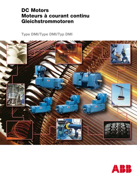
The background of the front-page shows a rotor for DMI 250 under construction.<br />
Das Hintergrundbild auf der Titelseite zeigt einen unfertigen Rotor von einem DMI 250-Motor.<br />
Le fond de la couverture représente un rotor de DMI 250 en construction.<br />
DMI 05/09 Rev 2.0
1<br />
General<br />
Généralités<br />
Allgemeines<br />
Catalogue validity 6<br />
Validité du catalogue<br />
Gültigkeit des Katalogs<br />
Patent 6<br />
Brevet<br />
Patent<br />
Motor/generator option 6<br />
Option moteur/génératrice<br />
Motor/Generator-Option<br />
Direction of rotation 6<br />
Sens de rotation<br />
Drehsinn<br />
Definition of motor ends 6<br />
Définition des extrémités de la machine<br />
Definition det Motorenden<br />
Type designation 6<br />
Désignation du type<br />
Typenbezeichtnung<br />
Standards 7<br />
Normes<br />
Normen<br />
Environment impact 7<br />
Impact sur l’environnement<br />
Umweltbeeinflussung<br />
Warranty 7<br />
Garantie<br />
Garantie<br />
Mounting arrangements 8<br />
Dispositions de montage<br />
Bauformen<br />
Internal and external environmental conditions 9<br />
Conditions ambiantes intérieures et extérieures<br />
Innere und äussere Umweltbedingungen<br />
Location of cooling equpment 9<br />
Positionnement de l’équipement de refroidissement<br />
Anordnung der Kühlerausrüstung<br />
Shipping details 9<br />
Détails d’expédition<br />
Transportart<br />
Degrees of protection 10<br />
Degrés de protection<br />
Schutzarten<br />
Methods of cooling 11<br />
Mode de refroidissement<br />
Kühlarten<br />
DMI 05/09 Rev 2.0 5
General<br />
Généralités<br />
Allgemeines<br />
Catalogue validity<br />
Information given in this catalogue is<br />
subject to modification in the interest<br />
of technical progress without further<br />
notice.<br />
Patent<br />
DMI patents pending.<br />
Motor/generator option<br />
The DMI are designed as variable<br />
speed motors, but can also be used<br />
as generators. The corresponding data<br />
can be supplied on request.<br />
Direction of rotation<br />
The motors listed in this catalogue are<br />
suitable for rotation in either direction.<br />
Definition of motor ends<br />
Unless otherwise stated in the order,<br />
the following definition applies.<br />
D-end N-end<br />
Commutator<br />
Type designation<br />
The DMI motor series has seven different<br />
centre heights. For each centre<br />
height there are several motor types<br />
with lengths increasing in steps. For<br />
each motor length different armature<br />
windings are available giving various<br />
base speeds with the same voltage.<br />
Example: DMI 180B - CBA<br />
DM = DC Motor<br />
I = Motor type<br />
180 = Centre height in mm<br />
B = Core length<br />
CB = Winding number<br />
A = Speed range<br />
Validité du catalogue<br />
Les informations contenues dans ce<br />
catalogue sont sujettes à modifica-tion<br />
sans préavis dans l’intérêt du progrès<br />
technique.<br />
Brevet<br />
Brevets DMI en cours d’homologation.<br />
Option moteur/génératrice<br />
Les machines sont prévues comme<br />
moteurs à vitesse variable, mais peuvent<br />
aussi être utilisées comme génératrices.<br />
Les renseignements correspondants<br />
peuvent être fournis sur<br />
demande.<br />
Sens de rotation<br />
Les moteurs figurant dans ce catalogue<br />
conviennent à la rotation dans<br />
l’un ou l’autre sens.<br />
Définition des extrémités de la<br />
machine<br />
Sauf indication contraire dans la<br />
com-mande, la définition suivante est<br />
valide.<br />
Côté entrînement Côté collecteur<br />
Collecteur<br />
Désignation du type<br />
La série de moteurs DMI a sept hauteurs<br />
d’axe différentes. Pour chaque<br />
hauteur d’axe, il y a plu-sieurs types<br />
de moteurs dont les longueurs augmentent<br />
par paliers. Pour chaque<br />
longueur de moteur, il y a un certain<br />
nombre de bobinages d’induit donnant<br />
diverses vitesses de base avec la<br />
même tension.<br />
Beispiel: DMI 180B - CBA<br />
DM = DC-Motor<br />
I = Motortyp<br />
180 = Achshöhe in mm<br />
B = Blechpaketlänge<br />
CB = Anzahl der Wicklungen<br />
A = Drehzahlbereich<br />
Gültigkeit des Katalogs<br />
Abweichungen von den Angaben<br />
dieses Katalogs bleiben vorbehalten,<br />
damit die Motoren stets dem letzten<br />
Stand der technischen Entwicklung<br />
entsprechen können.<br />
Patent<br />
DMI Patente in Bearbeitung.<br />
Motor/Generator-Option<br />
Die Maschinen sind als Motoren mit<br />
regelbarer Drehzahl ausgelegt, können<br />
aber auch als Generatoren verwendet<br />
werden. Die entsprechenden<br />
Daten sind auf Anfrage erhältlich.<br />
Drehsinn<br />
Die Motoren dieses Katalogs eignen<br />
sich für beide Drehrichtungen.<br />
Definition der Motorenden<br />
Soweit keine andere Übereinkunft<br />
vorliegt, gilt folgende Definition:<br />
D-Ende N-Ende<br />
Kommutator<br />
Typenbezeichnung<br />
Die DMI-Motoren sind mit sieben unterschiedlichen<br />
Achshöhen lieferbar.<br />
Für jede Achshöhe gibt es mehrere<br />
Motortypen in abgestuften Längen.<br />
Für jede Motorlänge gibt es eine<br />
Anzahl Läuferwicklungen für verschiedene<br />
Grunddrehzahlen bei derselben<br />
Spannung.<br />
Exemple : DMI 180B - CBA<br />
DM = Moteur DC<br />
I = Type de moteur<br />
180 = Hauteur du centre en mm<br />
B = Longueur du noyau<br />
CB = Numéro de bobinage<br />
A = Plage de vitesses<br />
DMI 05/09 Rev 2.0
Standards<br />
DMI motors comply with the requirements<br />
of the international standard<br />
IEC Publ. 00 -1. Further references<br />
to standards can be found in the<br />
respective chapter in this catalogue.<br />
Motors complying with other standards<br />
can be supplied on request.<br />
The DMI motor series is CE-marked<br />
according to EMC Directive 89/ /<br />
EEC and Low Voltage Directive /2 /<br />
EEC and 9 / 8/EEC. This series is also<br />
certified to be incorporated into machinery<br />
in accordance with the Machine<br />
Directive 89/ 92/EEC.<br />
The DMI motor series is approved<br />
according to CSA for voltages up to<br />
50V.<br />
Environment impact<br />
DMI is designed to give low environmental<br />
impact throughout its service<br />
life. This includes the manufacturing<br />
process, suppliers, use by customers<br />
and recycling.<br />
Warranty<br />
All products in this catalogue carry<br />
an 2 month warranty after delivery<br />
or a 12 month warranty after start up,<br />
whichever comes first. For longer<br />
warranty time contact ABB.<br />
DMI 05/09 Rev 2.0<br />
Normes<br />
Les moteurs DMI sont conformes aux<br />
exigences de la norme internationale<br />
CEI Publ. 00 -1. D’autres références<br />
aux normes se trouvent dans le chapitre<br />
correspondant de ce catalogue.<br />
Des moteurs conformes à d’autres<br />
normes peuvent être fournis sur demande.<br />
La série des moteurs DMI est marquée<br />
CE selon la directive CEM 89/ /CEE<br />
et la directive des basses tensions<br />
/2 /CEE et 9 / 8/CEE. Cette série<br />
est aussi certifiée pour être incluse<br />
dans une machine selon la directive<br />
des machines 89/ 92/CEE.<br />
La série de moteurs DMI est approuvée<br />
selon CSA pour les tensions<br />
jusqu’à 50 V.<br />
Impact sur l’environnement<br />
La série DMI est conçue pour ne<br />
produire qu’un faible impact sur l’environnement<br />
durant sa vie utile. Ceci<br />
inclut le processus de fabrication, les<br />
fournisseurs, l’utilisation par les clients<br />
et le recyclage.<br />
Garantie<br />
Tous les produits de ce catalogue sont<br />
garantis 2 mois à partir de la date de<br />
livraison ou 12 mois après mise en<br />
service. Pour prolonger la durée de<br />
garantie, prière de contacter ABB.<br />
General<br />
Généralités<br />
Allgemeines<br />
Normen<br />
Die DMI-Motoren entsprechen<br />
der internationalen Empfehlung<br />
IEC 00 - 1. Auf weitere Normen<br />
wird in den jeweiligen Abschnitten<br />
dieses Katalogs Bezug genommen.<br />
Motoren gemäß anderen Normen sind<br />
auf Anfrage erhältlich.<br />
Die DMI-Motoren sind entsprechend<br />
der EMC-Richtlinie 89/ /EEC und<br />
der Niederspannungsrichtlinie /2 /<br />
EEC und 9 / 8/EEC CE-gekennzeichnet.<br />
Diese Baureihe ist außerdem<br />
zertifiziert, im Einklang mit der<br />
Maschinenrichtlinie 89/ 92/EEC. Die<br />
DMI–Motoren sind auch nach CSA für<br />
Spannungen bis 50 V zugelassen.<br />
Umweltbeeinflußung<br />
Die DMI-Reihe wurde so entwickelt,<br />
daß sie während ihrer gesamten Betriebszeit<br />
die Umwelt nur in geringem<br />
Maß beeinflußt. Dies schließt den<br />
Herstellungsprozeß, die Zukaufsteile,<br />
den Einsatz beim Kunden und das<br />
Recycling mit ein.<br />
Gewährleistung<br />
Auf alle in diesem Katalog beschriebenen<br />
Motoren wird eine Gewährleistung von<br />
12 Monaten nach Inbetriebnahme oder<br />
max. 24 Monaten nach Lieferung gewährt.<br />
ABB berät Sie gerne im Hinblick<br />
auf eine mögliche Garantieverlängerung.<br />
1
General<br />
Généralités<br />
Allgemeines<br />
Mounting arrangements<br />
The motors can be mounted as shown<br />
below. Designations are in accordance<br />
with IEC Publ. 00 - .<br />
Other mounting arrangements on<br />
request<br />
Foundation, motor itself and fastening of<br />
motor always works together as a system.<br />
All systems (applications) independent<br />
of make and type of motor always have<br />
a certain so called “critical speed” where<br />
very high vibrations appear even if balancing<br />
is perfect.<br />
In an application with foot mounted motor<br />
on rigid foundation the critical speed<br />
always is much higher than the maximum<br />
speed in operation and consequently<br />
there is no problem with vibration.<br />
Normally there is no vibration problem<br />
with a foot mounted motor if mass of<br />
foundation is 5 times the mass of the<br />
motor or higher.<br />
Foundations with low stiffness or low<br />
stiffness at the fastening point like flange<br />
mounting sometimes lead to a critical<br />
speed within the speed range in operation.<br />
If motor is running at or close to the<br />
critical speed for a period of time damage<br />
can occur on the motor. Fast acceleration<br />
through the critical speed is not harmful.<br />
The critical speed for flange mounted<br />
motors can be increased by adding a rigid<br />
support at the pair of motor feets farthest<br />
away from the flange.<br />
8<br />
Dispositions de montage<br />
Les moteurs peuvent être montés<br />
comme indiqué ci-dessous. Les<br />
désignations sont conformes à CEI<br />
Publ. 00 - .<br />
IM 1001 IM 1002 IM 1061 IM 1051 IM 1071<br />
*)<br />
IM 1011 IM 1031 IM 2001 IM 2011 IM 2031<br />
Autres dispositions de montage sur<br />
demande<br />
Fondations, moteur proprement dit et<br />
fixation de moteur fonctionnent toujours<br />
ensemble et forment un système. Tous les<br />
systèmes (applications), indépendamment<br />
de la marque et du type de moteur, ont<br />
toujours une certaine « vitesse critique» à<br />
laquelle apparaissent de très fortes vibrations,<br />
même si l’équilibrage est parfait.<br />
Dans une application à moteur monté<br />
sur pied sur des fondations rigides, la<br />
vitesse critique est toujours beaucoup<br />
plus élevée que la vitesse maximale en<br />
service et il n’y a donc aucun problème<br />
de vibrations.<br />
Il n’y a en principe pas de problème de<br />
vibrations avec un moteur monté sur<br />
pied si la masse des fondations est 5 fois<br />
élevée ou plus, que celle du moteur.<br />
Les fondations peu rigides ou à point de<br />
fixation peu rigide, comme dans le cas<br />
du montage sur brides, ont parfois pour<br />
conséquence que la vitesse critique se<br />
trouve au sein de la plage de vitesses<br />
de la machine en service. Si le moteur<br />
tourne pendant un certain temps à, ou à<br />
proximité de la vitesse critique, le moteur<br />
peut être endommagé. Une accélération<br />
Bauformen<br />
Folgende Bauformen gemäß IEC Publ.<br />
00 - sind lieferbar:<br />
*)<br />
Andere Bauformen auf Anfrage<br />
Das Fundament, der Motor selbst und<br />
seine Befestigung wirken stets als<br />
Gesamtsystem. Alle solchen Systeme<br />
(Applikationen) haben unabhängig von<br />
Motorbauart und –typ eine ”kritische<br />
Drehzahl”, bei der selbst unter optimal<br />
symmetrischer Belastung sehr hohe<br />
Schwingungen auftreten. Bei einer auf<br />
starrem Fundament fußmontierten Applikation<br />
ist die kritische Drehzahl immer<br />
höher als die maximale Betriebsdrehzahl,<br />
so dass dieser Schwingungseffekt kein<br />
Problem darstellt.<br />
Normalerweise tritt bei einem fußmontierten<br />
Motor kein Schwingungsproblem<br />
auf, solange die Masse des Fundaments<br />
mindestens fünfmal so hoch ist wie die<br />
des Motors.<br />
Wo Fundamente oder Befestigungsstellen<br />
(wie Flanschverbindungen) nur über<br />
geringe Steifigkeit verfügen, kann manchmal<br />
die kritische Drehzahl innerhalb des<br />
Betriebsdrehzahlbereichs liegen. Ein längerer<br />
Betrieb nahe der kritischen Drehzahl<br />
kann zu Motorschäden führen. Der Motor<br />
sollte schnell über die kritische Drehzahl<br />
hinaus hochgefahren werden.<br />
*)<br />
DMI 05/09 Rev 2.0
*) Access to the back of the flange by<br />
dismantling the covers. Threaded<br />
holes in the flange for fastening the<br />
motor can be provided on request.<br />
Note: DMI motors always have feet.<br />
Internal and external environmental<br />
conditions<br />
For applications where maximum<br />
cleaning interval is required, cooling<br />
air inlet at D-end is recommended.<br />
With cooling air inlet at D-end the<br />
rated output is usually reduced and<br />
the rating data has to be recalculated.<br />
See “Rating data at special conditions”,<br />
page 0. If humidity can be expected<br />
to fall below g/m , ABB should be<br />
consulted, as this must be considered<br />
to make a correct choice of carbon<br />
brush grade.<br />
Location of cooling equipment<br />
Fans can be located on the right or<br />
left, or above DMI motors. Heat exchangers<br />
must not be mounted on<br />
the same side as the terminal box is<br />
located.<br />
The fans can be rotated 180°, but normally<br />
the filter should not face directly<br />
towards the terminal box.<br />
If not otherwise specified on the<br />
delivery order, the cooling equipment<br />
will/must always be installed so that<br />
the cooling air enters at the N-end of<br />
the DMI motor.<br />
Shipping details<br />
Air/water and air/air heat exchangers<br />
are normally delivered separately.<br />
Unless otherwise specified, other accessories<br />
are supplied mounted on<br />
the DMI motor<br />
DMI 05/09 Rev 2.0<br />
rapide pour quitter la vitesse critique<br />
n’est pas dommageable.<br />
La vitesse critique pour les moteurs<br />
montés sur brides peut être augmentée<br />
en ajoutant un support rigide à la paire<br />
de pieds du moteur qui est le plus loin<br />
de la bride.<br />
*) Accès à l’arrière de la bride en démontant<br />
les carters. Des trous filetés de la<br />
bride pour la fixation du moteur sont<br />
disponibles sur demande.<br />
Note: les moteurs DMI ont toujours des<br />
pattes.<br />
Conditions ambiantes intérieures<br />
et extérieures<br />
Pour les applications exigeant des<br />
intervalles de nettoyage les plus<br />
longs possibles, il est recommandé<br />
de prévoir une admission d’air de<br />
refroidissement à côté entrînement.<br />
Avec une admission d’air de refroidissement<br />
à côté entrînement, la puissance<br />
nominale est généralement<br />
réduite et les valeurs nominales doivent<br />
être recalculées. Voir « Valeurs<br />
nominales en conditions spéciales »,<br />
page 0, dans cet addenda.<br />
Positionnement de l’équipement<br />
de refroidissement<br />
Les moto-ventilateurs peuvent être<br />
situés à droite, à gauche, ou sur le dessus<br />
des machines DMI. Les échangeurs<br />
ne doivent pas être montés du même<br />
côté que le boîtier de connexion.<br />
Les moto-ventilateurs peuvent être<br />
tournés de 180° mais normalement le<br />
filtre ne doit pas pas être directement<br />
orienté vers le boîtier de connexion.<br />
Sauf spécification contraire dans la<br />
commande, l’équipement de refroidissement<br />
sera toujours monté de telle<br />
sorte que l’air de refroidissement entre<br />
à côté collecteur de la machine DMI.<br />
Détails d’expédition<br />
Les échangeurs air/eau et air/air sont<br />
normalement livrés séparément.<br />
Sauf indication contraire, les autres<br />
accessoires sont livrés montés sur la<br />
machine DMI.<br />
General<br />
Généralités<br />
Allgemeines<br />
Bei flanschmontierten Motoren lässt sich<br />
die kritische Drehzahl heraufsetzen,<br />
indem man die beiden am weitesten vom<br />
Flansch entfernten Ständerfüße versteift.<br />
*) Zugang zur Rückseite des Flansches<br />
nach Demontage der Abdeckungen.<br />
Zur Flanschbefestigung des Motors<br />
können auf Wunsch Gewindebohrungen<br />
vorgesehen werden.<br />
Hinweis: Alle DMI–Motoren haben Füße.<br />
Innere und äußere Umweltbedingungen<br />
Bei Anwendungen, bei denen maximale<br />
Reinigungsintervalle erforderlich<br />
sind, wird Kühllufteinlaß am D-Ende<br />
empfohlen. Bei Kühllufteinlaß am<br />
D-Ende verringert sich in der Regel<br />
die Nennleistung und die Nenndaten<br />
müssen neu berechnet werden. Siehe<br />
dazu den Punkt „Nenndaten bei speziellen<br />
Bedingungen” in dieser Ergänzung.<br />
(Seite 0)<br />
Anordnung der Kühlausrüstung<br />
Lüfter können rechts, links oder oben<br />
an die DMI-Maschinen angebaut werden.<br />
Wärmetauscher dürfen nicht auf<br />
der selben Seite wie der Klemmenkasten<br />
montiert werden.<br />
Die Lüfter können um 180° gedreht<br />
werden, aber das Filter darf nicht<br />
direkt gegen den Klemmenkasten<br />
gerichtet sein.<br />
Ist nichts anderes in der Bestellung<br />
angegeben worden, ist die Kühlausrüstung<br />
stets so anzubauen, daß die<br />
Kühlluft am N-Ende der DMI-Maschine<br />
eintritt.<br />
Transportart<br />
Luft/Wasser- und Luft/Luft-Wärmetauscher<br />
werden normalerweise separat<br />
geliefert.<br />
Wenn nichts anderes vereinbart<br />
wurde, werden andere Zubehörteile<br />
werkseitig am DMI-Motor montiert.<br />
9<br />
1
General<br />
Généralités<br />
Allgemeines<br />
Degrees of protection<br />
The motors can be supplied with the<br />
following degrees of protection in accordance<br />
with IEC 00 -5<br />
IP 23<br />
Protected against spraying water<br />
within 0° from the vertical and<br />
contact with live parts by fingers or<br />
objects larger than 12 mm. Normally<br />
for indoor use.<br />
IP 54<br />
Protected against dust, splashing<br />
water from any direction and contact<br />
with live parts.<br />
For use in dusty and/or humid environments.<br />
If used outdoors, suitable<br />
protection against storm winds<br />
carrying foreign material should be<br />
provided.<br />
When ambient temperatures below<br />
0 °C can be expected, the risk of ice<br />
formation on fan blades and in cooling<br />
ducts must be taken into consideration.<br />
IP 55<br />
Protected against dust, jets of water<br />
from any direction and contact with<br />
live parts.<br />
For use in exposed locations, outdoors<br />
or indoors. Where tropical<br />
storms occur, the motor should be<br />
enclosed within screen walls and a<br />
roof to provide protection against flying<br />
debris.<br />
When ambient temperatures below<br />
0 °C can be expected, the risk of ice<br />
formation on fan blades and in cooling<br />
ducts must be taken into consideration.<br />
10<br />
Degrés de protection<br />
Les moteurs peuvent être fournis<br />
avec les degrés de protection suivants<br />
conformément à CEI 00 -5:<br />
IP 23<br />
Protection contre les projections d’eau<br />
jusqu’à 0° de la verticale et contre le<br />
contact avec les parties sous tension<br />
par les doigts ou les objets de plus de<br />
12 mm. Normalement pour utilisation<br />
intérieure.<br />
IP 54<br />
Protection contre la poussière, les projections<br />
d’eau dans n’importe quelle<br />
direction et le contact avec les parties<br />
sous tension.<br />
Pour utilisation dans les environnements<br />
poussiéreux et/ou humides.<br />
En cas d’utilisation extérieure, prévoir<br />
une protection appropriée contre les<br />
vents porteurs de débris volants.<br />
Lorsque des températures ambiantes<br />
inférieures à 0 °C sont à prévoir, tenir<br />
compte du risque de formation de givre<br />
sur les pales de ventilateur et dans<br />
les conduits de refroidissement.<br />
IP 55<br />
Protection contre la poussière, les jets<br />
d’eau dans n’importe quelle direction<br />
et le contact avec les parties sous<br />
tension.<br />
Pour utilisation dans les emplacements<br />
exposés, à l’extérieur ou à l’intérieur.<br />
En cas de tempête tropicale,<br />
la machine doit être enfermée dans<br />
une enceinte grillagée munie d’un toit<br />
pour assurer la protection contre les<br />
débris volants.<br />
Lorsque des températures ambiantes<br />
inférieures à 0 °C sont à prévoir, tenir<br />
compte du risque de formation de givre<br />
sur les pales de ventilateur et dans<br />
les conduits de refroidissement.<br />
Schutzarten<br />
Die Motoren können in folgenden<br />
Schutzarten nach der IEC Publ.<br />
00 - 5 geliefert werden:<br />
IP 23<br />
Schutz gegen Sprühwasser bis 0°<br />
von der Senkrechten und Berührung<br />
rotierender oder unter Spannung stehender<br />
Teile mit den Fingern oder mit<br />
Fremdkörpern über 12 mm. Normal<br />
für Verwendung in Innenräumen mit<br />
trockner, wenig verunreinigter Luft.<br />
IP 54<br />
Schutz gegen schädliche Staubablagerung<br />
und Spritzwasser aus allen<br />
Richtungen sowie vollständiger Berührungsschutz.<br />
Für Verwendung unter staubigen und/<br />
oder feuchten Umweltbedingungen.<br />
Bei Aufstellung im Freien ist für entsprechenden<br />
Schutz gegen Unwetter<br />
und dergleichen zu sorgen.<br />
Sind Temperaturen unter 0 °C zu erwarten,<br />
muß das Risiko der Vereisung<br />
von Lüfterflügeln und Kühlkanälen<br />
beachtet werden.<br />
IP 55<br />
Schutz gegen schädliche Staubablagerung<br />
und Strahlwasser aus allen<br />
Richtungen sowie vollständiger Berührungsschutz.<br />
Für Verwendung in ausgesetzten<br />
Bereichen in Innenräumen oder im<br />
Freien. Wo tropische Stürme vorkommen,<br />
sind Abschirmungen und<br />
Überdachungen zum Schutz gegen<br />
fliegende Teile vorzusehen.<br />
Sind Temperaturen unter 0 °C zu erwarten,<br />
muß das Risiko der Vereisung<br />
von Lüfterflügeln und Kühlkanälen<br />
beachtet werden.<br />
DMI 05/09 Rev 2.0
Methods of cooling<br />
The cooling forms comply with IEC<br />
Publ. 00 - . The recommended<br />
method of cooling is determined by<br />
the environment and the location of<br />
the motor.<br />
The cooling form selected should<br />
supply cooling air for DC motors at<br />
temperatures between –5 and + 0 °C.<br />
Motors for operation at other temperatures<br />
can be supplied on request.<br />
Standard DMI-motors have the cooling<br />
air intake at the N-end. Modified versions<br />
with the air intake at the D-end<br />
can be supplied on request. A cooling<br />
air inlet from below is available as a<br />
modification.<br />
For use in aggressive atmospheres<br />
containing chlorine, sulphur, potassium<br />
etc., a closed cooling system in<br />
which the DC motor is cooled with air<br />
at over-pressure from a clean source<br />
is recommended.<br />
For motors with heat exchangers, the<br />
pick-up air filter is replaced with a<br />
connection to the clean air supply.<br />
The aggressive environmental air<br />
should also be prevented from entering<br />
the motor during non-operational<br />
periods.<br />
DMI 05/09 Rev 2.0<br />
Mode de refroidissement<br />
Les modes de refroidissement sont<br />
conformes à CEI Publ. 00 - . Le<br />
mode de refroidissement recommandé<br />
est déterminé par l’environnement et<br />
l’emplacement du moteur.<br />
Le mode de refroidissement choisi<br />
doit fournir de l’air de refroidissement<br />
pour les moteurs c.c. à des températures<br />
comprises entre –5 et + 0<br />
°C. Des moteurs pouvant fonctionner<br />
à d’autres températures peuvent être<br />
fournis sur demande.<br />
Les machines DMI standard ont leur<br />
prise d’air de refroidissement à côté<br />
collecteur. Des versions modifiées<br />
avec prise d’air à côté entrînement<br />
peuvent être fournies sur demande.<br />
Une entrée d’air de refroidissement<br />
par-dessous est disponible comme<br />
modification.<br />
Pour les atmosphères corrosives<br />
contenant du chlore, du soufre, du<br />
potassium, etc., un système de refroidissement<br />
fermé dans lequel le moteur<br />
c.c. est refroidi par de l’air pressurisé<br />
provenant d’une source propre<br />
est recommandé.<br />
Pour moteurs avec échangeurs de<br />
chaleur, le filtre de prise d’air est<br />
remplacé par un raccord à la source<br />
d’air propre.<br />
Il convient également d’empêcher l’air<br />
du milieu corrosif de pénétrer dans<br />
le moteur pendant les périodes de<br />
repos.<br />
General<br />
Généralités<br />
Allgemeines<br />
Kühlarten<br />
Die Kühlarten entsprechen der IEC<br />
Publ. 00 - . Bei der Wahl der<br />
Kühlart müssen die Umgebungsbedingungen<br />
am Aufstellungsort der<br />
Maschine berücksichtigt werden.<br />
Bei der gewählten Kühlart sollte die<br />
Kühlluft für Gleichstrommotoren im<br />
Temperaturbereich zwischen -5 und<br />
+ 0 °C liegen. Motoren für Betrieb bei<br />
anderen Temperaturen sind auf Anfrage<br />
erhältlich.<br />
In der Standardausführung haben<br />
die DMI-Maschinen die Kühlluft-Eintrittsöffnung<br />
am N-Ende. Modifizierte<br />
Ausführungen mit Lufteintritt am D-<br />
Ende sind lieferbar. Als Modifikation<br />
ist auch Kühllufteintritt von unten auf<br />
Anfrage erhältlich.<br />
Für Verwendung in aggressiver, z. B.<br />
chlor-, schwefel- oder kohlenoxid-haltiger<br />
Atmosphäre empfiehlt sich ein<br />
geschlossenes Kühlsystem, in dem der<br />
Gleichstrommotor unter Überdruck<br />
mit reiner Luft vom von außerhalb<br />
gekühlt wird.<br />
Bei Motoren mit Wärmetauscher ist<br />
das Leckluftfilter durch einen Anschluss<br />
an saubere Luft zu ersetzen.<br />
Ein Eindringen der aggressiven Umgebungsluft<br />
sollte auch während Stillstandsperioden<br />
vermieden werden.<br />
11<br />
1
General<br />
Généralités<br />
Allgemeines<br />
Degrees of protection and methods of cooling<br />
Degrés de protection et modes de refroidissement<br />
Schutsarten und Kühlarten<br />
12<br />
IP Methods of cooling Modes de refroidissement Kühlarten<br />
IP 23 IC 06 IC 06 IC 06<br />
Motor-mounted fan Ventilateur monté sur Durchzugbelüftung<br />
and free circulation moteur et circulation durch aufgebauten<br />
libre Fremdlüfter<br />
IP 23 IC 17 IC 17 IC 17<br />
Ducted air supply and Conduits d’alimentation Durchzugbelüftung mit<br />
free circulation d’air et circulation libre getrenntem Kühllufteintritt<br />
IP 54 / IP 55 IC 37 IC 37 IC 37<br />
Ducted air supply and Conduits d’alimentation Getrennter Kühlluft-<br />
exhaust et d’évacuation d’air eintritt und -austritt<br />
IP 54 / IP 55 IC 86 W IC 86 W IC 86 W<br />
Motor-mounted Echangeur de chaleur Aufgebauter Luft/Wasser-<br />
air/water heat exchanger air/eau monté sur Kühler<br />
moteur<br />
IP 54 / IP 55 IC 666 IC 666 IC 666<br />
Motor-mounted Echangeur de chaleur Aufgebauter Luft/Luft-<br />
air/air heat exchanger air/air monté sur Kühler<br />
moteur<br />
IP 54 / IP 55 IC 410 IC 410 IC 410<br />
Totally enclosed frame- Entièrement fermé Oberflächenkühlung<br />
cooled without fan refroidi par la carcasse, ohne Lüfter<br />
(Data on request) sans ventilateur (Daten auf Anfrage)<br />
(Information sur<br />
demande)<br />
Other degrees of protection Autres degrés de protection Andere Kombinationen<br />
and methods of cooling et modes de refroidissement von Schutz- und Kühlart<br />
on request. disponibles sur demande. auf Anfrage.<br />
DMI 05/09 Rev 2.0
2<br />
Mechanical design<br />
Conception mécanique<br />
Mechanische Ausführung<br />
Stator 14<br />
Stator<br />
Ständer<br />
Stator windings 14<br />
Enroulements de stator<br />
Ständerwicklungen<br />
Compensation winding 15<br />
Enroulement de compensation<br />
Kompensationswicklung<br />
Armature 15<br />
Induit<br />
Läufer<br />
Armature winding 15<br />
Enroulement d’induit<br />
Läuferwicklung<br />
Shaft 16<br />
Arbre<br />
Welle<br />
End shields 19<br />
Plateaux-paliers<br />
Lagerschilde<br />
Drain holes for enclosed motors 19<br />
Trous de drainage pour moteurs fermés<br />
Kondenswasserlöcher für geschlossene Motoren<br />
Brush gear 19<br />
Ensemble porte-balais<br />
Bürstenbrücke<br />
Terminal box and cable entry 20<br />
Schéma de raccordement<br />
Klemmenkasten und Kabeleinführung<br />
Terminal diagram 21<br />
Conditions ambiantes intérieures et extérieures<br />
Klemmenschaltbild<br />
Bearings 21<br />
Paliers<br />
Lager<br />
Lubrication 22<br />
Lubrification<br />
Schmierung<br />
Drive couplings 22<br />
Transmission<br />
Antriebe<br />
Pulleys 24<br />
Poulies<br />
Riemenantriebe<br />
Permissible shaft loads 25<br />
Charges autorisées sur l’arbre<br />
Zulässige Wellenbelastungen<br />
Axial bearing loads 28<br />
Charges axiales sut les paliers<br />
Axialen Lagerbelastungen<br />
Noice level 29<br />
Niveau sonore<br />
Geräusche<br />
Insulation system 30<br />
Système d’isolement<br />
Isolationssystem<br />
Foundation loads from the motor 31<br />
Charges exercées aux fondations par le moteur<br />
Beanspruchung des Fundaments durch Motoren<br />
Rating plate 31<br />
Plaque signalétique<br />
Typenschild<br />
DMI 05/09 Rev 2.0 1<br />
2
Mechanical design<br />
Conception mécanique<br />
Mechanische Ausführung<br />
Stator<br />
The frame, main poles and interpoles<br />
are fully laminated. This ensures<br />
good commutation even during rapid<br />
current changes. The stator components<br />
are welded together in a fixture,<br />
which both aligns and presses the<br />
plates together to form a solid unit.<br />
The square shape of the DMI-motor<br />
allows simple installation of accessories<br />
and air ducts and large openings<br />
for inspection.<br />
Stator windings<br />
The stator windings are of dual coat<br />
type-insulated copper wire. The stator<br />
is impregnated to make the windings<br />
sturdy and moisture resistant. The<br />
connections are brazed or crimped to<br />
withstand overloads.<br />
Compensating winding<br />
Frame sizes DMI 180-225 have no<br />
compensating winding. Frame sizes<br />
DMI 250-280 are available with two<br />
different designs, uncompensated or<br />
with compensating winding, reaching<br />
different performance. Frame sizes<br />
DMI 15 and 00 are equipped with<br />
compensation winding.<br />
1<br />
Stator<br />
Stator<br />
Ständer<br />
Stator<br />
La carcasse, les pôles principaux et<br />
les pôles de commutation sont entièrement<br />
feuilletés. Cela assure une<br />
bonne commutation même lors des<br />
changements rapides de courant. Les<br />
composants du stator sont soudés<br />
ensemble dans un bâti de fixation qui<br />
aligne et presse les plaques ensemble<br />
en une unité monobloc.<br />
La forme carrée du moteur DMI permet<br />
un montage facile des accessoires<br />
et des conduits d’air et ménage de<br />
grandes ouvertures d’inspection.<br />
Enroulements de stator<br />
Les enroulements de stator sont en fil<br />
de cuivre isolé verni. Le stator est imprégné<br />
pour rendre les enroule-ments<br />
robustes et résistants à l’humidité. Les<br />
connexions sont brasées ou serties<br />
pour supporter les surintensités.<br />
Enroulement de compensation<br />
Les dimensions de carcasses de DMI<br />
250 - 280 sont disponibles en deux<br />
versions, avec ou sans enroulement<br />
de compensation, qui présentent des<br />
performances différentes. Les tailles<br />
de cadres DMI 15 et 00 sont équipés<br />
d’un bobinage de compensation.<br />
Ständer<br />
Jochring, Haupt- und Wendepole<br />
sind vollgeblecht. Hierdurch wird<br />
gute Kommutierung auch während<br />
schneller Stromänderungen bei<br />
Stromrichterbetrieb sichergestellt. Die<br />
Ständerkomponenten sind in einer<br />
Spannvorrichtung, in der die Bleche<br />
sowohl ausgerichtet als auch zusammengepreßt<br />
werden, zu einer massiven<br />
Einheit verschweißt.<br />
Die viereckige Form des DMI-Motors<br />
vereinfacht den Anbau von Zubehörteilen<br />
und Kühlluftrohren. Ein zusätzlicher<br />
Vorteil sind große Inspektionsöffnungen.<br />
Ständerwicklungen<br />
Die Ständerwicklungen bestehen aus<br />
lackisoliertem Kupferdraht. Die Wicklungen<br />
werden durch Imprägnierung<br />
des Ständers versteift und feuchtigkeitsbeständig.<br />
Die Wicklungsverbin-dungen<br />
sind hartgelötet oder<br />
kontaktgepreßt, um Überlastungen zu<br />
vertragen.<br />
Kompensationswicklung<br />
Die Baugrößen DMI 250 - 280 sind<br />
in zwei verschiedenen Ausführungen<br />
mit unterschiedlicher Leistung lieferbar,<br />
unkompensiert oder mit<br />
einer Kompensationswicklung. Die<br />
Baugrößen DMI 15 und 00 werden<br />
mit einer Kompensationswicklung<br />
ausgeliefert<br />
DMI 05/09 Rev 2.0
Armature<br />
Induit<br />
Läufer<br />
Armature<br />
The armature core consists of discs<br />
of high grade insulated electroplates<br />
and incorporates a large number of<br />
cooling ducts. The core package is<br />
pressed onto the armature shaft with a<br />
high interference fit to ensure torque<br />
transfer.<br />
The commutator, as standard, is located<br />
at the N-end and has high mechanical<br />
and thermal capacity.<br />
The armature is dynamically balanced.<br />
Balancing weights are fastened on<br />
commutator hub (N-end) and winding<br />
support (D-end).<br />
Low losses together with efficient<br />
cooling result in an efficient motor<br />
with high output/weight ratio, without<br />
over stressing the materials.<br />
As standard the armature is mechanically<br />
designed to occasionally withstand<br />
a speed that is 20 % higher than<br />
the max mechanical speed specified<br />
for each catalogue number on data<br />
sheet.<br />
Armature winding<br />
The armature winding is of dual coat<br />
type-insulated copper. The copper<br />
coils are placed in enveloping slot insulation<br />
and held in the slots by glass<br />
fibre tape.<br />
The winding is designed to give very<br />
low commutating stresses. This gives<br />
the margin required to minimize<br />
maintenance by means of brush grade<br />
optimization. It also allows speed control<br />
over a wide speed range.<br />
Induit<br />
Le noyau d’induit est constitué de<br />
disques en tôles électromagnétiques<br />
isolées, de haute qualité, comportant<br />
un grand nombre de conduits de<br />
refroidissement. Le noyau est pressé<br />
contre l’arbre de l’induit par une interférence<br />
élevée à même d’assurer le<br />
transfert de couple.<br />
Le positionnement standard du collecteur<br />
est à côté collecteur et il possède<br />
une capacité mécanique et thermique<br />
élevée.<br />
L’induit est équilibré dynamiquement.<br />
Des disques d’équilibrage sont montés<br />
sur le moyeu du collecteur (côté<br />
collecteur) et sur le support d’enroulement<br />
(côté entrînement).<br />
Les faibles charges et le refroidissement<br />
efficace assurent un moteur<br />
performant à rapport puissance/poids<br />
élevé, sans contrainte excessive des<br />
matériaux.<br />
En standard, l’induit est mécaniquement<br />
conçu pour supporter<br />
occasionnellement une vitesse de 20<br />
% supérieure à la vitesse mécanique<br />
maximale indiquée pour chaque<br />
numéro de catalogue sur des fiches<br />
techniques.<br />
Enroulement d’induit<br />
Le bobinage d’armature est de type<br />
en fil de cuivre à double enduction.<br />
Les bobinages de cuivre sont enrobés<br />
dans l’isolant des encoches et maintenus<br />
dans les encoches par une clavette<br />
de fibre de verre.<br />
L’enroulement est conçu pour donner<br />
des contraintes de commutation<br />
peu élevées. Cela permet d’obtenir la<br />
marge requise pour réduire l’entretien<br />
grâce à l’optimisation de la qualité des<br />
balais ainsi qu’une bonne régulation<br />
sur une large plage de vitesse.<br />
Mechanical design<br />
Conception mécanique<br />
Mechanische Ausführung<br />
Läufer<br />
Der Kern des Läufers besteht aus<br />
hochwertigem, isoliertem Dynamoblech<br />
und enthält eine große Anzahl<br />
Kühlkanäle. Das Läuferblechpaket ist<br />
auf die Läuferwelle mit hoher Interferenzanpaßung<br />
aufgepreßt, um die<br />
Drehmomentübertragung sicherzustellen.<br />
Der Kommutator, der in Standardausführung<br />
am N-Ende angeordnet ist,<br />
besitzt hohe mechanische und thermische<br />
Stabilität.<br />
Der Läufer wird dynamisch ausgewuchtet.<br />
Dies geschieht durch Anbringen<br />
von Gewichtsstücken an der<br />
Kommutatornabe (N-Ende) und am<br />
Wicklungsständer (D-Ende).<br />
Niedrige Verluste und eine wirkungsvolle<br />
Kühlung ergeben einen Motor<br />
mit einem hohen Leistungs/ Gewichtsverhältnis<br />
ohne Überbeanspruchung<br />
der Werkstoffe.<br />
Standardmäßig ist der Läufer mechanisch<br />
so konzipiert, daß er kurzfristig<br />
Drehzahlen standhalten kann, die<br />
20 % über der max. mechanischen<br />
Drehzahl liegen, die für jeden Motortyp<br />
auf dem Datenblatt angegeben<br />
sind.<br />
Läuferwicklung<br />
Die Läuferwicklung besteht doppelt<br />
lackisoliertem Kupfer. Die Kupferspulen<br />
sind von einer Nutenisolierung<br />
umgeben und werden durch Glasfaserbandagen<br />
in den Nuten fixiert.<br />
Die Wicklung ist für niedere Kommutierungsbelastung<br />
ausgelegt. Somit<br />
kann der Wartungsaufwand durch Optimierung<br />
der Bürstenqualität auf ein<br />
Minimum reduziert werden. Es ermöglicht<br />
zudem eine Drehzahlregelung<br />
über einen weiten Drehzahlbereich.<br />
DMI 05/09 Rev 2.0 15<br />
2
Mechanical design<br />
Conception mécanique<br />
Mechanische Ausführung<br />
The entire armature is impregnated to<br />
ensure a high degree of heat transfer<br />
and good protection against dust. The<br />
coil ends are TIG-welded to the commutator.<br />
The welding points withstand<br />
overloading and overheating.<br />
Shaft<br />
The standard shaft end is provided<br />
with a key. Shaft extensions and<br />
keyways are according to DIN 8,<br />
part , to VSM 152 , and to IEC<br />
Recommendations 00 2-1 or 00 2-2,<br />
however some shaft extensions do not<br />
have shaft shoulder (see further under<br />
chapter ”Maximum torque for standard<br />
shafts”, page 18.<br />
The armature has a high critical speed<br />
and is resistant to bending to permit<br />
V-belt drive (see further under chapter<br />
“Pulleys”). For drives with rapid and<br />
frequent changes in the direction of<br />
torque, looseness can occur between<br />
shaft, key and coupling. DMI motors<br />
can be ordered with a special shaft<br />
end without key for shrink fit couplings<br />
to avoid this.<br />
The maximum torque Mmax which<br />
can be transmitted by standard shaft<br />
extensions with diameter D are in<br />
accordance with the table “Maximum<br />
torque for standard shafts”, page 18.<br />
With some exceptions standard DMI<br />
can be mounted mechanically in<br />
tandem. When needed, a modified<br />
design for higher torque is available<br />
to allow mounting in tandem e.g. See<br />
notes to table “Maximum torque for<br />
standard shafts”, page 18.<br />
1<br />
Shaft<br />
Arbre<br />
Welle<br />
L’induit tout entier est imprégné, ce<br />
qui assure un transfert thermique<br />
efficace et une bonne protection<br />
contre la poussière. Les extrémités du<br />
bobinage sont soudées au collecteur.<br />
Les points de soudage supportent la<br />
surcharge et la surchauffe.<br />
Arbre<br />
L’extrémité d’arbre standard est munie<br />
d’une clavette. Les bouts d’arbre et les<br />
rainures de clavetage sont conformes<br />
à DIN 8, partie , à VSM 152 et<br />
aux Recommandations 00 2-1 ou<br />
00 2-2 ; cependant, certaines rallonges<br />
d’arbre n’ont pas d’épaulement<br />
d’arbre (voir ci-après au chapitre<br />
”Couple maximum pour arbres standard”,<br />
page 18.<br />
L’induit a une vitesse critique élevée<br />
et sa résistance à la flexion permet<br />
l’emploi d’une transmission par courroie<br />
trapézoïdale (voir plus loin au<br />
chapitre «Poulies»). Pour les transmissions<br />
à changements rapides de direction<br />
du couple, il peut se produire<br />
du jeu entre arbre, clavette et accouplement.<br />
Pour éviter cela, les moteurs<br />
DMI peuvent être commandés avec<br />
un bout d’arbre spécial sans clavette<br />
pour les accouplements à ajustement<br />
à chaud.<br />
Le couple maximum Mmax pouvant<br />
être transmis par des bouts d’arbre<br />
standards de diamètre D est indiqué<br />
dans le tableau « Couple maximum<br />
pour arbres standards », page 18.<br />
A quelques exceptions près, les<br />
moteurs DMI standards peuvent être<br />
montés mécaniquement en tandem.<br />
Si nécessaire, des versions modifiées<br />
à couple plus élevé sont disponibles,<br />
notamment pour permettre le montage<br />
en tandem. Voir notes du tableau<br />
« Couple maximum pour arbres<br />
standards », page 18.<br />
Der gesamte Läufer erhält durch<br />
Imprägnierung ein gutes Wärmeleitvermögen<br />
und wird gleichzeitig staubabweisend.<br />
Die Spulenenden sind am<br />
Kommutator wolframinertverschweißt.<br />
Die Schweißpunkte halten hohe<br />
Überlastungen und Übertemperaturen<br />
stand.<br />
Welle<br />
Das standardmäßige Wellenende ist<br />
Mit einer Paßfeder versehen. Wellenenden<br />
und Paßfedern sind gemäß<br />
DIN 8, Teil , VSM 152 und IEC<br />
Empfehlungen 00 2-1 oder 00 2-2<br />
ausgeführt. Allerdings besitzen einige<br />
Wellenverlängerungen keinen Absatz<br />
(siehe ”Maximales Drehmoment<br />
für Standardwellen”, seite 18 weiter<br />
unten). Der Läufer hat eine hohe<br />
kritische Drehzahl und erlaubt dank<br />
seiner Biegefestigkeit Keilriemenantrieb<br />
(siehe weiteres im Abschnitt<br />
„Riemenantriebe“). Bei Antrieben<br />
mit schnellen und häufigen Änderungen<br />
der Drehmomentrichtung, z.<br />
B. in Umkehrwalzenstraßen, kann<br />
Spiel zwischen Welle, Paßfeder und<br />
Kupplung entstehen. Um dies zu<br />
vermeiden, können DMI-Motoren in<br />
Sonderausführung mit Wellenende<br />
ohne Paßfedernut für Kupplung mit<br />
Schrumpfsitz angeboten werden.<br />
Das höchste Drehmoment Mmax , das<br />
von einem Standardwellenende mit<br />
Durchmesser D übertragen werden<br />
kann, ist aus der Tabelle „Maximales<br />
Drehmoment für Standardwellen”<br />
ersichtlich. (Seite 18)<br />
Standard-DMI können mit wenigen<br />
Ausnahmen mechanisch als Tandem<br />
gekoppelt eingesetzt werden. Auf<br />
Anfrage sind modifizierte Konstruktionen<br />
für höhere Drehmomente<br />
erhältlich, die unter anderem eine<br />
gekoppelte Montage ermöglichen.<br />
Siehe dazu Anmerkungen zur Tabelle<br />
„Maximales Drehmoment für Standardwellen”.<br />
(Seite 18)<br />
DMI 05/09 Rev 2.0
Note that overload torque can exceed<br />
the value stated in the data sheets.<br />
Mechanical dimensioning must therefore<br />
be calculated with higher overload,<br />
namely:<br />
- For uncompensated motors<br />
Tmax /T = 1 0 % at Imax /IN = 180 %<br />
- For DMI 250 and 280 with compensating<br />
winding<br />
Tmax /T = 185 % at Imax /IN = 200 %<br />
- For DMI 15 and 00<br />
Tmax /T = 195 % at Imax /IN = 200 %<br />
Even higher torque, special shaft extensions<br />
and special shaft steels are<br />
available on request.<br />
Noter que le couple de surcharge<br />
risquera d’être supérieur à la valeur<br />
indiquée dans les fiches techniques.<br />
C’est pourquoi le dimensionnement<br />
mécanique devra être recalculé avec<br />
une surcharge supérieure, notamment<br />
:<br />
- Moteurs non compensés<br />
Tmax /T = 1 0 % à Imax /IN = 180 %<br />
- Pour DMI 250 et 280 avec bobinage<br />
de compensation<br />
Tmax /T = 185 % à Imax /IN = 200 %<br />
- DMI 15 et 00<br />
Tmax /T = 195 % à Imax /IN = 200 %<br />
Des bouts d’arbres spéciaux à couple<br />
plus élevé et des arbres en aciers<br />
spéciaux sont disponibles sur demande.<br />
Mechanical design<br />
Conception mécanique<br />
Mechanische Ausführung<br />
Es ist zu beachten, daß Überlast-Drehmomente<br />
die in den Datenblättern<br />
angegebenen Werte<br />
überschreiten können. Aus diesem<br />
Grund müssen bei der mechanischen<br />
Dimensionierung folgende andere<br />
Drehmomentwerte zugrunde gelegt<br />
werden:<br />
- Bei unkompensierten Motoren:<br />
Tmax /T = 1 0% bei Imax /IN = 180%<br />
- Bei Motoren Typ DMI 250 and 280<br />
mit Kompensationswicklung:<br />
Tmax /T = 185% bei Imax /IN = 200%<br />
- DMI 15 und 00<br />
Tmax /T = 195 % bei Imax /IN = 200 %<br />
Höhere Drehmomente, Sonderausführung<br />
von Wellenenden und Wellen<br />
in Sonderstählen sind auf Anfrage<br />
erhältlich.<br />
DMI 05/09 Rev 2.0 1<br />
2
Mechanical design<br />
Conception mécanique<br />
Mechanische Ausführung<br />
Maximum torque for standard shafts with key<br />
Couple maximal pour arbres standard avec clé<br />
Maximales Drehmoment für Standardwellen mit Passfedernut<br />
18<br />
End shield and brush holder<br />
Plateau-palier et porte-balais<br />
Lagerschild mit Bürstenhalter<br />
DMI 180-200 180-200 180-200 180 200 200<br />
B, E, H M, P, S, U B, E, H M, P, S, U M, P S, U<br />
IM IM xxx1 IM xxx1 IM xxx2 IM xxx2 IM xxx2 IM xxx2<br />
End/Extrémité/Ende D D D N D N D N D N<br />
D mm 60 65 65 60 70 65 70 65 70 65<br />
Mmax Nm 2720 3430 3430 2720 4250 3430 4250 3430 5800 3430<br />
Dmax mm 70m6 70m6 70m6 70m6 70m6 70m6 70m6 70m6 70m6 70m6<br />
DMI 225 225 225 225 225<br />
K,N,S,U,X K, N S U X<br />
IM IM xxx1 IM xxx2 IM xxx2 IM xxx2 IM xxx2<br />
End/Extrémité/Ende D D N D N D N D 1) D 2) N<br />
D mm 80 80 65 85 65 85 70 85 95 70<br />
Mmax Nm 6230 6230 3430 7430 3430 8790 5030 8790 12070 5030<br />
Dmax mm 85m6 85m6 70m6 85m6 70m6 85m6 70m6 85m6 100m6 70m6<br />
DMI 250-280 250 280 280 250 250 250 250<br />
L,P,T V, Y V Y L,P T V Y<br />
IM IM xxx1 IM xxx1 IM xxx1 IM xxx1 IM xxx2 IM xxx2 IM xxx2 IM xxx2<br />
End/Extrémité/Ende D D D D D N D N D 1) D 2) N D 1) D 2) N<br />
D mm 95 100 100 100 100 80 100 85 100 120 85 100 120 100<br />
Mmax Nm 10210 11840 11840 14010 11840 6230 14010 8790 14010 23650 8790 11840 19990 11840<br />
Dmax mm 100m6 100m6 100m6 100m6 100m6 85m6 100m6 85m6 100m6 120m6 85m6 100m6 120m6 100m6<br />
DMI 280 280 280 280 280 280 280<br />
L P T V V Y Y<br />
IM IM xxx2 IM xxx2 IM xxx2 IM xxx2 IM xxx2 IM xxx2 IM xxx2<br />
End/Extrémité/Ende D N D N D1) D 2) N D 1) N 1) D 2) N 2) D 1) N 1) D 3) N 3)<br />
D mm 100 80 100 80 100 120 100 100 100 120 100 100 100 120 100<br />
Mmax Nm 11840 6230 14010 7370 11840 19990 11840 11840 11840 23650 14010 14010 14010 23650 14010<br />
Dmax mm 100m6 85m6 100m6 85m6 100m6 120m6 100m6 100m6 100m6 120m6 100m6 100m6 100m6 120m6 100m6<br />
DMI 315 315 315 315 315 315 315<br />
H, L, N R, T, V, Y, Z H, L, N R, T V Y Z<br />
IM IM xxx1 IM xxx1 IM xxx2 IM xxx2 IM xxx2 IM xxx2 IM xxx2<br />
End/Extrémité/Ende D D D N D N D N D N D 3) N 3)<br />
D mm 130 140 140 130 140 140 150 140 150 140 150 140<br />
Mmax Nm 23760 29520 31160 25080 31160 31160 37860 31160 46200 38000 46200 38000<br />
Dmax mm 150m6 150m6 150m6 150m6 150m6 150m6 150m6 150m6 150m6 150m6 150m6 150m6<br />
DMI 400 400 400 400 400<br />
H, L, N R, T V Y Z<br />
IM IM xxx1 IM xxx1 IM xxx1 IM xxx1 IM xxx1<br />
End/Extrémité/Ende D D D D D<br />
D mm 130 140 150 150 180<br />
Mmax Nm 23760 29520 35870 43770 60480<br />
Dmax mm 150m6 150m6 150m6 150m6 190m6<br />
DMI 400 400 400 400 400 400<br />
H L N R, T V Y, Z<br />
IM IM xxx2 IM xxx2 IM xxx2 IM xxx2 IM xxx2 IM xxx2<br />
End/Extrémité/Ende D N D N D N D N D N D 3) N 3)<br />
D mm 140 130 150 130 150 130 180 140 190 150 190 150<br />
Mmax Nm 31160 25080 37860 25080 46200 30780 63840 31160 74860 37860 86400 46200<br />
Dmax mm 150m6 150m6 150m6 150m6 150m6 150m6 190m6 150m6 190m6 150m6 190m6 150m6<br />
1) Standard shaft design. If DMI is mounted mechanically in tandem overload must be reduced, not exceeding M max .<br />
Version d’arbre standard. Si le DMI est monté mécaniquement en tandem, la surcharge doit être réduite, ne dépassant pas M max .<br />
Standardwellenendenkonstruktion. Bei mechanischer Kopplung von DMI zum Tandem muß die Überlast verringert werden und M max nicht übersteigen.<br />
2) Modified shaft design allowing DMI e.g. to be mounted mechanically in tandem with full overload capacity.<br />
Version d’arbre modifiée permettant notamment le montage mécanique en tandem avec 100 % de capacité de surcharge.<br />
Modifizierte Wellenendenkonstruktion beispielsweise zur mechanischen Kopplung zum Tandem bei voller Überlast.<br />
3) Modified shaft design. Overload must be reduced, not exceeding M max , for DMI with compensating winding if mounted mechanically in tandem.<br />
Version d’arbre modifiée. La surcharge doit être réduite, ne dépassant pas M max , pour DMI avec enroulement de compensation en cas de<br />
montage mécanique en tandem<br />
Modifizierte Wellenendenkonstruktion. Bei mechanischer Kopplung von DMI mit Kompensationswicklung zum Tandem muß<br />
die Überlast verringert werden und darf M max nicht übersteigen.<br />
NB! No shaft shoulder if D=Dmax, except for D=120. Shaft shoulder available on request. Shrink fit data on request.<br />
N.B. ! Pas d’épaulement d’arbre si D=Dmax, sauf pour D=120. Épaulement d’arbre disponible sur demande. Données sur les accouplements à ajustement à chaud sur demande.<br />
Achtung! Kein Wellenabsatz wenn D = Dmax, außer bei D = 120. Wellenabsatz auf Wunsch möglich. Schrumpfsitzdaten auf Anfrage.<br />
DMI 05/09 Rev 2.0
End shields<br />
The end shields are of cast iron. The<br />
shaft runout and concentricity, and<br />
the perpendicularity of the mounting<br />
flange to the motor of flange mounted<br />
models, comply with IEC Recommendations<br />
00 2-2 for motors.<br />
Drain holes for enclosed motors<br />
DMI motors are fitted with drain holes<br />
located in the end shields.<br />
Brush gear<br />
The brush gear assembly is fitted to<br />
the end shield and insulated by a<br />
glass fibre reinforced plastic ring. The<br />
brush holders contain spring loaded<br />
pressure fingers.<br />
The brush gear assembly can be rotated<br />
when a brush change becomes<br />
necessary, a position device snaps to<br />
the right brush position again when<br />
rotating back to the original brush<br />
gear location.<br />
Plateaux-paliers<br />
Les plateaux-paliers sont en fonte. Le<br />
faux-rond, la concentricité de l’arbre<br />
et la perpendicularité de la bride de<br />
montage au moteur des modèles<br />
montés sur bride sont conformes aux<br />
recommandations CEI 00 2-2 pour<br />
les moteurs.<br />
Trous de drainage pour moteurs<br />
fermés<br />
Les moteurs DMI sont munis de trous<br />
de drainage situés dans les plateauxpaliers.<br />
Ensemble porte-balais<br />
L’ensemble porte-balais est assemblé<br />
au plateau-palier et isolé par une<br />
bague en plastique renforcée en fibre<br />
de verre. Les porte-balais contiennent<br />
des doigts de pression rappelés par<br />
ressort.<br />
Il est facile de faire tourner l’ensemble<br />
porte-balais quand un changement<br />
de balais devient nécessaire.<br />
Mechanical design<br />
Conception mécanique<br />
Mechanische Ausführung<br />
Lagerschilde<br />
Die Lagerschilde sind aus Gußeisen.<br />
Rundlauf, Konzentrizität und Rechtwinkligkeit<br />
des Wellenendes bei<br />
Flanschmotoren entsprechen der IEC-<br />
Empfehlung 00 2-2 für Motoren.<br />
Kondenswasserlöcher für<br />
geschlossene Motoren<br />
Die DMI-Motoren haben in den Lagerschilden<br />
Kondenswasserlöcher.<br />
Bürstenbrücke<br />
Die Bürstenbrücke ist am Lagerschild<br />
befestigt und mit einem verstärkten<br />
Glasfiberring isoliert. Die Bürstenhalter<br />
haben gefederte Druckfinger.<br />
Die Bürstenbrücke kann leicht gedreht<br />
werden, um Bürstenwechsel zu<br />
ermöglichen.<br />
DMI 05/09 Rev 2.0 19<br />
2
Mechanical design<br />
Conception mécanique<br />
Mechanische Ausführung<br />
Terminal box and cable entry<br />
The standard location of the terminal<br />
box is on top of the DMI motor with<br />
cable entrance from the right (facing<br />
D-end). The terminal box can also be<br />
placed on either the right or the left<br />
sides of the motor.<br />
The desired terminal box location<br />
must be specified when ordering.<br />
Later changes may not be possible.<br />
The cable entry location can be altered<br />
on site simply by turning the terminal<br />
box. To obtain optimal connection<br />
however, the desired cable entry<br />
location must be noted on the order.<br />
DMI motors are delivered with undrilled<br />
covers on the connection<br />
opening of the terminal box. The<br />
terminal markings are in accordance<br />
with the recommendations in IEC<br />
Publ. 00 -8.<br />
Connections can be made to ground<br />
both inside the terminal box and outside<br />
on the stator frame using a bolt<br />
(M8) located on the stator foot.<br />
A bigger terminal box is available for<br />
all DMI models.<br />
20<br />
Boîtier de connexion et<br />
entrée de câble<br />
L’emplacement standard du boîtier de<br />
connexion est sur le dessus du moteur<br />
DMI avec l’entrée de câble à droite<br />
(face à côté entrînement). Le boîtier de<br />
connexion peut aussi être placé sur les<br />
côtés droit ou gauche de la machine.<br />
L’emplacement souhaité du boîtier de<br />
connexion doit être spécifié à la commande.<br />
Des changements ultérieurs<br />
ne sont pas possibles.<br />
L’emplacement de l’entrée de câble<br />
peut être modifiée sur le site en tournant<br />
le boîtier de connexion. Cependant,<br />
pour obtenir une connexion<br />
optimale, l’emplacement de l’entrée<br />
de câble souhaitée doit être précisé à<br />
la commande.<br />
Les moteurs DMI sont livrés avec des<br />
carters non percés sur les ouvertures<br />
de raccordement du boîtier de<br />
connexion. Les marquages des bornes<br />
sont conformes aux recommandations<br />
de CEI Publ. 00 -8.<br />
Des connexions peuvent être effectuées<br />
pour mettre à la terre l’intérieur<br />
du boîtier de connexion et l’extérieur<br />
sur le stator à l’aide d’un boulon (M8)<br />
situé sur le pied du stator.<br />
Une plus grande boîte à bornes est<br />
disponible pour les tous les modèles<br />
de DMI.<br />
Terminal box<br />
Boîtier de connection<br />
Klemmenkasten<br />
Klemmenkasten und<br />
Kabeleinführung<br />
In der Standardausführung befindet<br />
sich der Klemmenkasten oben auf<br />
dem DMI-Motor mit Kabeleinführung<br />
rechts (auf D-Ende gesehen). Der<br />
Klemmenkasten kann auch auf der<br />
rechten bzw. linken Seite der Maschine<br />
angeordnet werden.<br />
Die gewünschte Anordnung des<br />
Klemmenkastens muß bei der<br />
Bestellung angegeben werden.<br />
Die Kabeleinführposition kann vor<br />
Ort durch einfaches Drehen des<br />
Klemmenkastens verändert werden.<br />
Für optimalen Anschluß muß die gewünschte<br />
Kabeleintrittsposition jedoch<br />
auf der Bestellung notiert werden.<br />
DMI-Motoren werden mit ungebohrten<br />
Abdeckungen auf der Anschlußöffnung<br />
des Klemmenkastens<br />
geliefert. Die Klemmenbezeichnungen<br />
entsprechen den Empfehlungen in<br />
IEC Publ. 00 -8.<br />
Die Erdungsanschlüsse können sowohl<br />
im Inneren des Klemmenkastens<br />
vorgenommen werden als auch außen<br />
am Ständerrahmen mit Hilfe eines<br />
M8-Bolzens, der sich am Ständerfuß<br />
befindet.<br />
Für alle DMI–Modelle ist ein größerer<br />
Klemmenkasten verfügbar.<br />
DMI 05/09 Rev 2.0
Terminal diagram<br />
Schéma de raccordement<br />
Klemmenshaltbild<br />
Terminal diagram<br />
The left terminal diagram above<br />
shows the connections for shunt<br />
wound motors with clockwise rotation<br />
when facing the D-end.<br />
Counter clockwise rotation is obtained<br />
by changing the polarity of either the<br />
field winding (F1,F2) or the armature<br />
winding (A1,A2), see right figure<br />
above.<br />
Terminals for accessories see the<br />
chapter “accessories”, page 1<br />
Bearings<br />
The motors are normally supplied<br />
with grease lubricated ball bearings.<br />
With belt drive, DMI motors must be<br />
ordered with a cylindrical roller bearing<br />
at the D-end.<br />
As standard axially locked bearings<br />
are placed on the N-end except for<br />
some vertically mounted DMI. See<br />
table “Bearing data”, page 22.<br />
The axially locked bearing can also<br />
be placed at the D-end on request.<br />
The calculated bearing service life<br />
(L10aah ) is valid provided that there<br />
are no external load except the<br />
weight of a standard coupling. L10aah is valid within the speed range up to<br />
nmax . Both values are listed for different<br />
applications in the table “Bearing<br />
data” below. Higher speeds on<br />
request.<br />
+ – + –<br />
A1 F2 F1 A2<br />
M<br />
+ + – –<br />
A1 F2 F1 A2<br />
Schéma de raccordement<br />
Le diagramme du terminal de gauche<br />
ci-dessus illustre les connexions pour<br />
les moteurs à bobinage shunt avec<br />
rotation en sens horaire si l’on regarde<br />
le côté entraînement. La rotation<br />
dans le sens antihoraire est obtenue<br />
en changeant la polarité, soit du<br />
bobinage de champ (F1,F2), soit du<br />
bobinage de l’armature (A1,A2), voir<br />
la figure de droite ci-dessus. Bornes<br />
pour accessoires, voir le chapitre “Accessoires”,<br />
page 1.<br />
Paliers<br />
Les moteurs sont normalement livrés avec<br />
roulements à billes graissés.<br />
Pour la transmission par courroie, les<br />
moteurs DMI doivent être commandés<br />
avec un roulement à rouleaux à côté<br />
entrînement.<br />
En standard, les paliers axialement<br />
verrouillés sont placés à côté collecteur,<br />
sauf pour certains DMI à montage<br />
vertical. Voir tableau « Caractéristiques<br />
des paliers », page 22.<br />
Sur demande, les paliers axialement<br />
verrouillés peuvent être placés à côté<br />
entrînement.<br />
La durée de vie calculée des roulements<br />
(L10aah ) est valable à condition<br />
qu’il n’y ait pas de charges extérieures,<br />
excepté le poids d’un accouplement<br />
standard. L10aah est valable dans<br />
la plage de vitesses jusqu’à nmax . Les<br />
deux valeurs sont indiquées pour<br />
différentes applications dans le tableau<br />
« Caractéristiques des paliers »<br />
ci-dessous. Vitesses plus élevées sur<br />
demande.<br />
Mechanical design<br />
Conception mécanique<br />
Mechanische Ausführung<br />
Klemmenschaltbild<br />
Das Klemmenschaltbild links obenzeigt<br />
die Rechtslaufschaltung (Drehrichtung<br />
im Uhrzeigersinn) von<br />
Nebenschlussmotoren, vom D-Ende<br />
aus betrachtet. Linkslauf wird durch<br />
Polaritätswechsel entweder an der<br />
Feldwicklung (F1, F2) oder der Ankerwicklung<br />
(A1, A2) erzielt, siehe Schaltbild<br />
rechts oben. Klemmenanschlüsse<br />
für Zubehör siehe Kapitel „Zubehör“,<br />
seite 1.<br />
Lager<br />
Die Motoren werden normalerweise<br />
mit fettgeschmierten Kugellagern<br />
geliefert.<br />
Für Riemenantriebe müssen DMI-<br />
Motoren mit Zylinderrollenlagern am<br />
D-Ende bestellt werden.<br />
Standardmäßig sind die Festlager<br />
außer bei senkrecht montierten DMI<br />
am N-Ende plaziert, siehe folgenden<br />
Abschnitt „Lagerdaten”, seite 22.<br />
Auf Anfrage kann das Festlager auch<br />
am D-Ende plaziert werden.<br />
Die angegebene Nennlebensdauer<br />
(L10aah ) gilt unter der Annahme, daß<br />
außer dem Gewicht einer Standardkupplung<br />
keine weiteren externen<br />
Lasten auftreten. Der Wert für L10aah gilt bei Drehzahlen bis zur höchsten<br />
mechanischen Drehzahl. Beide Werte<br />
sind für unterschiedliche Anwendungen<br />
in der fnachfolgenden Tabelle<br />
„Lagerdaten” aufgeführt. Höhere<br />
Drehzahlen auf Anfrage.<br />
DMI 05/09 Rev 2.0 21<br />
M<br />
2
Mechanical design<br />
Conception mécanique<br />
Mechanische Ausführung<br />
Bearing data<br />
Caractéristiques des paliers<br />
Lagerdaten<br />
Horisontal mounting. Standard design. Standard bearings, axially locked at N-end. L 10aah > 100,000 hours.<br />
Montage horizontal. Version standard. Paliers standards, verrouillés axialement à côté collecteur. L 10aah >100.000 heures.<br />
Horizontal Montage. Standarddesign. Standardlager, achsial gelagert am N-Ende. L 10aah > 100,000 Betriebsstunden.<br />
DMI 180-400<br />
n(max) 1)<br />
Horisontal mounting. Modified design. Roller bearing at D-end. Axially locked at N-end 5) . L 10aah = 50,000 hours.<br />
Montage horizontal. Version modifiée. Roulement à rouleaux à côté entrînement. Verrouillé axialement à côté collecteur 5 ). L 10aah = 50.000 heures.<br />
Horizontal Montage. Modifiziertes Design. Rollenlager am D-Ende. Achsial gelagert am N-Ende 5 ). L 10aah = 50,000 Betriebsstunden.<br />
DMI 180-400<br />
n(max) 2)<br />
Vertical mounting. Standard design. Standard bearings, axially locked at N-end. L 10aah > 60,000 hours.<br />
Montage vertical. Version standard. Paliers standards, verrouillés axialement à côté collecteur. L 10aah >60.000 heures.<br />
Senkrecht Montage. Standarddesign. Standardlager, achsial gelagert am N-Ende. L 10aah > 60,000 Betriebsstunden.<br />
DMI 180B 180E 180H 180M 180P 180S 180U 200B 200E 200H 200M 200P 200S 200U<br />
n(max) 1) 1) 1) 1) 1) 1) 2950 3) 1) 1) 1) 3450 3) 2650 3) 1950 3) 1300 3)<br />
DMI 225K 225N 225S 225U 225X 250L 250P 250T 250V 250Y 280L 280P 280T 280V 280Y<br />
n(max) 1950 3) 1450 3) 890 3) 630 3) 430 3) 1900 3) 1450 3) 730 3) 4) 4) 1250 3) 680 3) 4) 4) 4)<br />
Vertical mounting. Modified design. Standard bearings, axially locked at D-end 5) . L 10aah > 60,000 hours.<br />
Montage vertical. Version modifiée. Paliers standards, verrouillés axialement à côté entrînement 5) . L 10aah >60.000 heures.<br />
Senkrecht Montage. Modifiziertes Design. Standardlager, achsial gelagert am D-Ende 5) . L 10aah > 60,000 Betriebsstunden.<br />
DMI 225K 225N 225S 225U 225X 250L 250P 250T 250V 250Y 280L 280P 280T 280V 280Y<br />
n(max) 1) 1) 2200 3) 1700 3) 1300 3) 1) 1) 1) 2350 3) 1550 3) 1) 1) 1800 3) 1300 3) 840 3 )<br />
Vertical mounting. Modified design. Special bearing, axially locked at N-end 5) . L 10aah > 60,000 hours.<br />
Montage vertical. Version modifiée. Roulement spécial, verrouillé axialement à côté collecteur 5) . L 10aah >60.000 heures.<br />
Senkrecht Montage. Modifiziertes Design. Spezial-Lager, achsial gelagert am N-Ende 5) . L 10aah > 60,000 Betriebsstunden.<br />
DMI 180U 200M 200P 200S 200U 225S 225U 225X 250V 250Y 280T 280V 280Y<br />
n(max) 3200 3) 3200 3) 3200 3) 3200 3) 3200 3) 3200 3) 3200 3) 2250 3) 2600 3) 2600 3) 2600 3) 2050 3 ) 1350 3)<br />
Note: Data on request for vertical mounting of DMI 315 and 400.<br />
Remarque : Données sur demande pour montage vertical de DMI 315 et 400.<br />
Hinweis: Daten für die vertikale Montage von DMI315 und 400 auf Anfrage.<br />
1) n max in technical data sheets are valid.<br />
Les n max des fiches techniques sont valables.<br />
Die Werte für n max in den Datenblätter bleiben gültig.<br />
2) Compare nmax in pulley diagram (see following pages) with technical data sheets. The lowest value counts.<br />
Comparer n max dans le diagramme poulie (pages suivantes) et les fiches techniques. Prendre la valeur la moins élevée.<br />
Die Werte für n max im Riemenantriebsdiagramm (siehe folgende Seiten) mit den Werten der Datenblätter vergleichen.<br />
Es gilt der jeweils niedrigere Wert.<br />
3) Compare nmax in table with technical data sheets. The lowest value counts.<br />
Comparer n max du tableau et les fiches techniques. Prendre la valeur la moins élevée.<br />
Die Werte für n max aus der Tabelle mit den Werten der Datenblätter vergleichen. Es gilt der jeweils niedrigere Wert.<br />
4) Modified design is required.<br />
Version modifiée requise.<br />
Konstruktionsänderung erforderlich.<br />
5) Additional price and delivery time.<br />
Supplément prix et délai de livraison.<br />
Preisaufschlag und längere Lieferzeiten beachten.<br />
22<br />
DMI 05/09 Rev 2.0
Lubrication<br />
The standard motors have grease<br />
nipples at both the D-end and N-end.<br />
When regreasing through the grease<br />
nipples, excess grease is forced out<br />
through an opening in the outer bearing<br />
cover.<br />
Recommended greases are found in<br />
the Operating and Maintenance Instructions<br />
for DMI ( BSM 00 0 5-1).<br />
Recommended lubrication interval for<br />
a specific motor is engraved on the<br />
rating plate.<br />
Drive couplings<br />
Direct-drive couplings should be of<br />
the flexible or rigid types, which can<br />
compensate for parallel and angular<br />
misalignment and for axial displacement.<br />
In particular, they must compensate<br />
for the thermal expansion of<br />
the shaft and must not cause any load<br />
that exceeds the permissible bearing<br />
loads. Permissible bearing load on<br />
request.<br />
Lubrification<br />
Les moteurs standard comportent des<br />
graisseurs aux deux extrémités D et N.<br />
Lors du regraissage, l’excès de graisse<br />
est évacué par une ouverture dans le<br />
carter externe du palier.<br />
Pour les graisses recommandées,<br />
prière de consulter les Instructions de<br />
fonctionnement et de maintenance de<br />
DMI ( BSM 00 0 5-1).<br />
L’intervalle de lubrification recommandé<br />
pour un moteur spécifique est<br />
gravé sur la plaquette d’identification.<br />
Transmission<br />
Les accouplements directs doivent être<br />
de type flexible ou rigide, capables de<br />
compenser le désalignement parallèle<br />
et angulaire et le déplacement axial.<br />
Ils doivent en particulier compenser<br />
la dilatation thermique de l’arbre<br />
et ne doivent pas causer de charge<br />
dépassant les charges autorisées sur<br />
les paliers. Charges permises sur les<br />
paliers sur demande.<br />
Standard bearings and roller bearings<br />
Roulements standard et roulements à rouleaux<br />
Standardlager und Rollenlager<br />
Mechanical design<br />
Conception mécanique<br />
Mechanische Ausführung<br />
Schmierung<br />
Die Standardmotoren haben Schmiernippel<br />
am D- und N-Ende. Beim<br />
Nachschmieren durch die Schmiernippel<br />
wird überschüssiges Schmierfett<br />
durch eine Öffnung an der<br />
äußeren Wellenabdeckung herausgedrückt.<br />
Fettempfehlungen werden in den<br />
Betriebs- und Wartungsanleitungen<br />
für DMI ( BSM 00 0 5-1) ausgesprochen.<br />
Die für bestimmte Motoren empfohlenen<br />
Schmierintervalle sind in das<br />
Typenschild eingeschlagen.<br />
Antriebe<br />
Für direkte Kraftübertragung empfehlen<br />
sich elastische oder feste Kupplungen,<br />
die imstande sind, parallele<br />
Fluchtungsfehler, Winkelabweichungen<br />
und axiale Verschiebungen zu<br />
kompensieren. Insbesondere müssen<br />
sie die Wärmeausdehnung der Welle<br />
kompensieren und dürfen keine<br />
Überbelastung der Lager verursachen.<br />
Zulässige Überbelastung auf Anfrage.<br />
D-end N-end D-side roller bearing<br />
Côté entrînement Côté collecteur Roulement à rouleaux du côté entraînement<br />
DMI D-Ende N-Ende Rollenlager D-Ende<br />
180 SKF 6214-C3 SKF 6214-C3 SKF N/NU 214ECP-C3<br />
200 SKF 6214-C3 SKF 6214-C3 SKF N/NU 214ECP-C3<br />
225 SKF 6217-C3 SKF 6214-C3 SKF N/NU 217ECP-C3<br />
250 SKF 6220-C3 SKF 6217-C3 SKF N/NU 220ECP-C3<br />
280 SKF 6220-C3 SKF 6217-C3 SKF N/NU 220ECP-C3<br />
315 SKF 6030-C4 SKF 6030-C4 SKF NU 230 ECJ-C3<br />
400 SKF 6230-C4 SKF 6230-C4 SKF NU 230 ECJ-C3<br />
DMI 05/09 Rev 2.0 2<br />
2
Mechanical design<br />
Conception mécanique<br />
Mechanische Ausführung<br />
Pulleys<br />
Motors for belt drives must be ordered<br />
with a roller bearing at the<br />
D-end, instead of the standard ball<br />
bearing.<br />
The minimum belt pulley diameter<br />
D (mm) can be obtained from the<br />
formula:<br />
P<br />
D = 19,1 10 6<br />
K c<br />
n<br />
2<br />
F r<br />
F r = Permissible radial shaft load, in N<br />
(see following pages).<br />
Note: F r is determined at average<br />
speed.<br />
P = rated output of motor, in kW.<br />
n = motor base speed in r/min.<br />
D = minimum pulley diameter in mm.<br />
K c = belt tension factor from the belt<br />
manufacturer, normally:<br />
For flat belts: ,5<br />
For V-belts:<br />
2,0 with uncompensated DMI.<br />
2, with compensated DMI.<br />
The permissible shaft load is based on<br />
a bearing life of L 10aah = 50.000 hours.<br />
Diagrams with permissible radial<br />
shaft load for pulleys (Fr ) are only<br />
valid for mounting arrangements IM<br />
1001, IM 1051, IM 10 1 and IM 10 1.<br />
Other mounting arrangements with<br />
pulleys on request.<br />
Pulley dimensions and load centre<br />
(see figure above).<br />
DMI<br />
Amax mm<br />
Xmax mm<br />
180 215 140<br />
200 215 140<br />
225 295 170<br />
250L,P,T 305 170<br />
250V,Y 305 210<br />
280L,P,T 385 170<br />
280V,Y 385 210<br />
Note that some diagrams in the<br />
following pages covers more than allowed<br />
speed and/or Xmax according<br />
to the table.<br />
15 & 00 on request<br />
A<br />
X<br />
max.10<br />
Poulies<br />
Les moteurs prévus pour une transmission<br />
à courroie doivent être<br />
commandés avec un roulement à<br />
rouleaux à côté entrînement, au lieu<br />
du roulement à billes standard. Le<br />
diamètre minimum D (mm) de poulie<br />
de courroie peut être obtenu par la<br />
formule:<br />
P<br />
D = 19,1 10 6<br />
K c<br />
n Fr Fr = charge radiale sur arbre autorisée, en N<br />
(voir pages suivantes).<br />
Note: Fr est calculé à vitesse moyenne.<br />
P = puissance nominale du moteur, en kW.<br />
n = régime de base du moteur, en tr/min.<br />
D = diamètre minimum de la poulie, en mm.<br />
Kc = facteur de tension de la courroie indiqué par<br />
le fabricant, normalement :<br />
Courroies plates : ,5<br />
Courroies trapézoïdales :<br />
2,0 avec DMI non compensé.<br />
2, avec DMI compensé.<br />
La charge autorisée sur l’arbre est basée<br />
sur une durée de vie des paliers<br />
de L10aah = 50.000 heures.<br />
Les diagrammes de charges radiales<br />
autorisées sur l’arbre pour poulies<br />
(Fr ) sont uniquement valables pour<br />
les dispositions de montage IM 1001,<br />
IM 1051, IM 10 1 et IM 10 1. Autres<br />
dispositions de montage avec poulies<br />
sur demande.<br />
Le tableau ci-contre indique les<br />
dimensions de poulie et le centre de<br />
charge pour DMI 250 et 280 (voir<br />
figure dans le catalogue principal).<br />
Noter que certains diagrammes des<br />
pages suivantes couvrent davantage<br />
d’éléments que la vitesse autorisée<br />
et/ou Xmax ci-contre.<br />
15 & 00 sur demand<br />
F r<br />
D<br />
Riemenantriebe<br />
Für Riemenantriebe müssen DMI-<br />
Motoren mit Zylinderrollenlagern<br />
am D-Ende bestellt werden. Für den<br />
Mindestdurchmesser D (mm) der Riemenscheibe<br />
gilt folgende Formel:<br />
P<br />
D = 19,1 10 6<br />
K c<br />
n<br />
Fr = Querkraft an der Welle, in N<br />
(siehe folgende Seiten).<br />
Note: Fr wird bei Durchschnitts<br />
drehzahl ermittelt.<br />
P = Nennleistung des Motors, kW<br />
n = Motor-Basisdrehzahl, min-1 D = min. Riemenscheibendurchmesser,<br />
mm<br />
Kc = Riemenspannungsfaktor laut<br />
Riemenhersteller, normalerweise:<br />
Für Flachriemen: ,5<br />
Für Keilriemen:<br />
2,0 bei unkompensierten DMI<br />
2, bei DMI mit Kompensationswicklung<br />
Die zulässige Querkraft an der<br />
Welle bezieht sich auf eine Lagerlebensdauer<br />
von L10aah = 50.000 Betriebsstunden.<br />
Die Diagramme mit Querkraft an der<br />
Welle für Riemenscheiben (Fr ) gelten<br />
nur für die Bauformen IM1001,<br />
IM 1051, IM 10 1 und IM 10 1. Auf<br />
Anfrage sind Diagramme für andere<br />
Bauformen mit Riemenscheiben<br />
erhältlich.<br />
Die folgende Tabelle enthält Riemenantriebsmaße<br />
und Lastangriffspunkte<br />
für die Baugrößen DMI 180 bis 280.<br />
Es ist zu beachten, daß einige der<br />
Diagramme auf den folgenden Seiten<br />
mehr als denzulässigen Xmax-Wert gemäß Tabelle aufweisen.<br />
15 & 00 auf Anfrage<br />
F r<br />
DMI 05/09 Rev 2.0
Permissible shaft loads with<br />
roller bearings<br />
DMI 180 – 200 B, E, H, M, P, S<br />
roller bearing/roulement à rouleaux /Rollenlager<br />
Fr (N)<br />
19000<br />
18000<br />
17000<br />
16000<br />
15000<br />
14000<br />
13000<br />
12000<br />
11000<br />
10000<br />
9000<br />
8000<br />
7000<br />
0 20 40 60 80 100 120 140<br />
X(mm)<br />
DMI 225<br />
roller bearing/roulement à rouleaux/Rollenlager<br />
Fr (N)<br />
32000<br />
31000<br />
30000<br />
29000<br />
28000<br />
27000<br />
26000<br />
25000<br />
24000<br />
23000<br />
22000<br />
Charges autorisées sur l’arbre<br />
avec roulements à rouleaux<br />
500 rpm<br />
580<br />
670<br />
780<br />
900<br />
1040<br />
1200<br />
1390<br />
1610<br />
1870<br />
2160<br />
2500<br />
2900<br />
3360<br />
3890<br />
4500<br />
21000<br />
300 rpm<br />
20000<br />
350<br />
19000<br />
410<br />
490<br />
18000<br />
570<br />
670<br />
17000<br />
790<br />
16000<br />
930<br />
1100<br />
15000<br />
1290<br />
14000<br />
13000<br />
1510<br />
1780<br />
2090<br />
2460<br />
12000<br />
11000<br />
2890<br />
3400<br />
0 10 30 50 70 90 110 130 150 170<br />
X(mm)<br />
Mechanical design<br />
Conception mécanique<br />
Mechanische Ausführung<br />
Zulässige Wellenbelastungen mit<br />
Rollen-lagern<br />
DMI 180 – 200 U<br />
roller bearing/roulement à rouleaux/Rollenlager<br />
DMI 05/09 Rev 2.0 25<br />
Fr (N)<br />
19000<br />
18000<br />
17000<br />
16000<br />
15000<br />
14000<br />
13000<br />
12000<br />
11000<br />
10000<br />
9000<br />
8000<br />
500<br />
580<br />
670<br />
780<br />
900<br />
1040<br />
1200<br />
7000<br />
0 20 40 60 80 100 120 140<br />
X(mm)<br />
DMI 250<br />
roller bearing/roulement à rouleaux/Rollenlager<br />
Fr (N)<br />
52000<br />
50000<br />
48000<br />
46000<br />
44000<br />
42000<br />
40000<br />
38000<br />
36000<br />
34000<br />
32000<br />
30000<br />
28000<br />
26000<br />
24000<br />
22000<br />
20000<br />
18000<br />
16000<br />
14000<br />
1390 rpm<br />
1610<br />
1870<br />
2160<br />
2500<br />
2900<br />
3360<br />
3890<br />
4500<br />
200 rpm<br />
240<br />
280<br />
340<br />
400<br />
480<br />
570<br />
690<br />
820<br />
970<br />
1160<br />
1390<br />
1650<br />
1970<br />
2350<br />
12000<br />
0 10 30 50 70 90 110 130 150 170 190<br />
2800<br />
210<br />
X(mm)<br />
2
Mechanical design<br />
Conception mécanique<br />
Mechanische Ausführung<br />
DMI 280<br />
roller bearing/roulement à rouleaux/Rollenlager<br />
Fr (N)<br />
51000<br />
49000<br />
47000<br />
45000<br />
43000<br />
41000<br />
39000<br />
37000<br />
35000<br />
33000<br />
31000<br />
29000<br />
27000<br />
25000<br />
23000<br />
21000<br />
19000<br />
17000<br />
15000<br />
1650<br />
13000<br />
1970<br />
11000<br />
2350<br />
9000<br />
7000<br />
2800<br />
0 10 30 50 70 90 110 130 150 170 190 210<br />
X(mm)<br />
2<br />
DMI 315 Y<br />
roller bearing/roulement á rouleaux/Rollenlager<br />
Fr (N)<br />
90000<br />
80000<br />
70000<br />
60000<br />
50000<br />
40000<br />
30000<br />
20000<br />
10000<br />
0<br />
200<br />
240<br />
280<br />
340<br />
400<br />
480<br />
570<br />
690<br />
820<br />
200 rpm<br />
240<br />
280<br />
340<br />
400<br />
480<br />
570<br />
690<br />
820<br />
970<br />
1160<br />
1390<br />
0 25 50 75 100 125 150 175 200 225 250<br />
X(mm)<br />
970 rpm<br />
1160<br />
1390<br />
1650<br />
DMI 315 H,L,N,R,T,V<br />
roller bearing/roulement á rouleaux/Rollenlager<br />
Fr (N)<br />
90000<br />
80000<br />
70000<br />
60000<br />
50000<br />
40000<br />
30000<br />
20000<br />
10000<br />
0<br />
DMI 315 Z<br />
roller bearing/roulement á rouleaux/Rollenlager<br />
Fr (N)<br />
90000<br />
80000<br />
70000<br />
60000<br />
50000<br />
40000<br />
30000<br />
20000<br />
10000<br />
0<br />
200<br />
240<br />
280<br />
340<br />
400<br />
480<br />
200-240<br />
280<br />
340<br />
400<br />
480<br />
570<br />
690<br />
820<br />
970<br />
1160<br />
0 25 50 75 100 125 150 175 200 225 250<br />
X(mm)<br />
570 rpm<br />
690<br />
820<br />
970<br />
1160<br />
1390<br />
1650<br />
0 25 50 75 100 125 150 175 200 225 250<br />
X(mm)<br />
1390 rpm<br />
1650<br />
DMI 05/09 Rev 2.0
DMI 400 H,L,N,R,T<br />
roller bearing/roulement á rouleaux/Rollenlager<br />
Fr (N)<br />
90000<br />
80000<br />
70000<br />
60000<br />
50000<br />
40000<br />
30000<br />
20000<br />
10000<br />
0<br />
200<br />
240<br />
280<br />
340<br />
400<br />
480<br />
570<br />
690<br />
820<br />
970<br />
0 25 50 75 100 125 150 175 200 225 250<br />
X(mm)<br />
DMI 400 Y<br />
roller bearing/roulement á rouleaux/Rollenlager<br />
Fr (N)<br />
90000<br />
80000<br />
70000<br />
60000<br />
50000<br />
40000<br />
30000<br />
20000<br />
10000<br />
0<br />
200<br />
240<br />
280<br />
340<br />
400<br />
480<br />
570<br />
690<br />
820<br />
970<br />
1150<br />
1360<br />
1600<br />
1850<br />
0 25 50 75 100 125 150 175 200 225 250<br />
X(mm)<br />
2200 rpm<br />
1150 rpm<br />
1360<br />
1600<br />
1850<br />
2200<br />
Mechanical design<br />
Conception mécanique<br />
Mechanische Ausführung<br />
DMI 400 V<br />
roller bearing/roulement á rouleaux/Rollenlager<br />
DMI 05/09 Rev 2.0 2<br />
Fr (N)<br />
90000<br />
80000<br />
70000<br />
60000<br />
50000<br />
40000<br />
30000<br />
20000<br />
10000<br />
0<br />
200<br />
240<br />
280<br />
340<br />
400<br />
480<br />
570<br />
690<br />
820<br />
970<br />
1150<br />
1360<br />
0 25 50 75 100 125 150 175 200 225 250<br />
X(mm)<br />
DMI 400 Z<br />
roller bearing/roulement á rouleaux/Rollenlager<br />
Fr (N)<br />
90000<br />
80000<br />
70000<br />
60000<br />
50000<br />
40000<br />
30000<br />
20000<br />
10000<br />
0<br />
200-1360<br />
1600-1850<br />
2200<br />
0 25 50 75 100 125 150 175 200 225 250<br />
X(mm)<br />
1600 rpm<br />
1850<br />
2200<br />
2
Axial bearing loads<br />
Permissible axial bearing loads for<br />
vertical standard motors are listed<br />
below. Bearings for higher loads are<br />
available on request.<br />
Motors for other combinations of load<br />
direction and mounting arrangement<br />
are available on request.<br />
28<br />
F<br />
F<br />
Charges axiales sur les paliers<br />
Les charges axiales autorisées pour<br />
les moteurs standard verticaux sont<br />
indiquées ci-dessous. Des roule-ments<br />
prévus pour des charges supérieures<br />
peuvent être fournis sur demande.<br />
Des moteurs pour d’autres combinaisons<br />
de direction de charge et<br />
d’installation de montage sont disponibles<br />
sur demande.<br />
DMI 180<br />
B E H M P S U<br />
F (N) 910 1020 1160 1350 1510 1690 1910<br />
DMI 200<br />
B E H M P S U<br />
F (N) 1030 1160 1340 1570 1760 1990 2250<br />
DMI 225<br />
K N S U X<br />
F (N) 2120 2450 2890 3240 3650<br />
DMI 250<br />
L P T V Y<br />
F (N) 3110 3570 4170 4670 5260<br />
DMI 280<br />
L P T V Y<br />
F (N) 3600 4180 4930 5590 6320<br />
Mechanical design<br />
Conception mécanique<br />
Mechanische Ausführung<br />
Axialen Lagerbelastungen<br />
Die zulässigen axialen Lagerbelastungen<br />
für Standardmotoren in<br />
senkrechter Anordnung sind nachstehend<br />
gelistet.<br />
Motoren mit anderen Kobinationen<br />
von AXialkräften und Montagearten<br />
sind auf Anfrage erhältlich.<br />
DMI 315<br />
H L N R T V Y Z<br />
F (N) 5460 5900 6410 7060 7770 8640 9650 10850<br />
DMI 400<br />
H L N R T V Y Z<br />
F (N) 7730 8430 9300 10300 11480 12900 14570 16930<br />
DMI 180 – 400<br />
F (N) Data on request / Information sur demande / Daten auf Anfrage<br />
DMI 05/09 Rev 2.0
Mechanical design<br />
Conception mécanique<br />
Mechanische Ausführung<br />
Noise level<br />
Running at full load with a thyristor<br />
fed power supply and with a motor<br />
mounted fan, the sound pressure<br />
levels of the DMI motors comply<br />
with IEC 00 -9. The sound level is<br />
depending on the power output and<br />
speed of the motor in accordance<br />
with IEC 00 -9.<br />
In addition the quotient between AC<br />
voltage to the converter and the DC<br />
voltage from the converter also exert<br />
an influence on the sound level. A<br />
low value of the quotient is recommended.<br />
To reduce noise level, silencers and<br />
reactors are available. Ducted air supply<br />
and exhaust (IC ) and heat exchangers<br />
(IC and IC 8 W) reduce<br />
the noise level as well.<br />
Niveau de bruit<br />
En pleine charge, avec une alimentation<br />
à thyristor et un ventilateur monté<br />
sur le moteur, les moteurs DMI ont en<br />
principe un niveau de pression sonore<br />
conforme à IEC 00 -9. Le niveau de<br />
bruit dépend de la puissance et de la<br />
vitesse du moteur, conformément à<br />
IEC 00 -9.<br />
De plus, le rapport entre la tension alternative<br />
qui alimente le convertisseur<br />
et la tension continue provenant du<br />
convertisseur a également une influence<br />
sur le niveau de bruit.<br />
Une faible valeur du rapport est recommandée.<br />
Afin de réduire le niveau de bruit, des<br />
silencieux et des réacteurs sont disponibles.<br />
Des conduits pour l’arrivée<br />
et l’extraction d’air (IC ) et des<br />
échangeurs de chaleur (IC et IC<br />
8 W) réduisent également le niveau<br />
de bruit.<br />
Betriebsgeräusch<br />
Der unter voller Betriebslast und mit<br />
motormontiertem Lüfter von thyristorgespeisten<br />
DMI-Motoren erzeugte<br />
Schalldruckpegel erfüllt die Anforderungen<br />
gemäß IEC 00 -9. Das Betriebsgeräusch<br />
ist von der Leistungsabgabe<br />
und Drehzahl des Motors gemäß<br />
IEC 00 -9 abhängig.<br />
Maßgeblich für den Schalldruckpegel<br />
ist auch der Umrichtungsfaktor des<br />
Stromrichters.<br />
Dieser Faktor sollte möglichst niedrig<br />
sein.<br />
Für die Reduzierung der Geräuschbelastung<br />
sind Schalldämpfer und Drosseln<br />
verfügbar.<br />
Getrennte Kühllufteintritte und –austritte<br />
(IC ) sowie Wärmetauscher (IC<br />
und IC 8 W) tragen ebenfalls zur<br />
Geräuschdämpfung bei.<br />
DMI 05/09 Rev 2.0 29
Insulation system<br />
The motors in this catalogue comply<br />
with the requirements of Class 200<br />
insulation. The insulation system is<br />
moisture resistant and is suitable for<br />
use in tropical climates without modification.<br />
Armature coils and stator windings<br />
have dual insulation coats. The base<br />
coat is a polyesterimide with a top<br />
coat of polyamide-imide enamel.<br />
Insulation to earth is of amid fibre<br />
(Nomex). All windings are impregnated<br />
with varnish, which gives a high<br />
mechanical strength.<br />
Copper wire insulation, Nomex and<br />
the impregnation varnish have a<br />
temperature index well above class<br />
H. There is therefore a large margin<br />
of safety in addition to high overload<br />
capacity.<br />
0<br />
Système d’isolement<br />
Les moteurs figurant dans ce catalogue<br />
sont conformes aux normes<br />
d’isolement de classe 200. Le système<br />
d’isolement offre une résistance à<br />
l’humidité et convient à l’utilisation<br />
sous les climats tropicaux sans modifications.<br />
Les bobinages d’induit et les enrou-lements<br />
de stator comportent une double<br />
protection isolante. La protection<br />
de base est un Polyester-imide recouvert<br />
d’un émail en polyamide-imide.<br />
L’isolation à la terre est en fibre amide<br />
(Nomex). Tous les enroulements sont<br />
imprégnés de vernis qui assure une<br />
résistance mécanique élevée.<br />
L‘isolement des fils de cuivre et le<br />
vernis d’imprégnation ont des indices<br />
de température largement supérieurs<br />
à la classe H. Outre une capacité de<br />
surcharge élevée, il y a donc une large<br />
marge de sécurité.<br />
Mechanical design<br />
Conception mécanique<br />
Mechanische Ausführung<br />
Isolationssystem<br />
Die Motoren dieses Katalogs erfüllen<br />
die Forderungen der Isolierstoffklasse<br />
200, entspricht 200 °C. Ein Isolationssystem,<br />
das feuchtigkeitsbeständig<br />
ist, und für den Einsatz in tropischem<br />
Klima ohne Modifikationen verwendet<br />
werden.<br />
Die Läufer- und Ständerwicklungen<br />
sind mit Polyesterlack beschichtet.<br />
Die Isolierung zur Erde besteht aus<br />
Amidfaser (Nomex). Alle Wicklungen<br />
erhalten durch die Lackimprägnierung<br />
eine hohe mechanische Festigkeit.<br />
Die höchstzulässige Dauertemperatur<br />
der verwendeten Isolierstoffe und<br />
Tränkmittel liegt auf Isolierstoffklasse<br />
H. Die Grenzübertemperatur wird also<br />
mit reichlichem Sicherheitszuschlag<br />
eingehalten, was ein hohes Überlastungsvermögen<br />
bedeutet.<br />
DMI 05/09 Rev 2.0
Mechanical design<br />
Conception mécanique<br />
Mechanische Ausführung<br />
Foundation loads from the motor<br />
(IM 1001 or IM 1002 mounting)<br />
All values given as load on the<br />
foundation in N/stator foot (negative<br />
values indicate tension).<br />
Fg ± Fd = Dynamic force<br />
Fg ± Fk = Max static force<br />
Fg = 1/4 x static force of gravity<br />
(accessories included)<br />
Fd = Additional dynamic force<br />
at maximum overload<br />
according to data tables<br />
(Fd is directly proportional<br />
to shaft torque).<br />
Fk = Additional static force if a<br />
short circuit occurs.<br />
DMI 180 DMI 200 DMI 225<br />
B E H M P S U B E H M P S U K N S U X<br />
F d (N) 1300 1700 2200 2900 3400 4000 4800 1800 2300 2900 3800 4500 5300 6300 3700 4800 6200 7300 8600<br />
F k (N) 5400 7000 9000 11600 13700 16300 19300 7200 9200 11900 15300 18200 21500 25500 15000 19400 25000 29600 35100<br />
DMI 250 DMI 280<br />
Charges exercées aux fonda-tions<br />
par le moteur (montage selon<br />
IM1001 ou IM1002)<br />
Toutes les valeurs sont données en<br />
tant que charge exercée sur la fondation<br />
en N/pied du stator (les valeurs<br />
négatives indiquent une traction).<br />
Fg ± Fd = Force dynamique<br />
Fg ± Fk = Force statique maximum<br />
Fg = 1/4 x force de gravité statique<br />
(accessoires inclus).<br />
Fd = Force dynamique supplémentaire<br />
à 200 % du couple nominal<br />
(Fd est directement proportionnel<br />
au couple de l’arbre).<br />
Fk = Force statique supplémentaire<br />
en cas de court-circuit.<br />
L P T V Y L P T V Y<br />
F d (N) 4800 6200 8000 9500 11200 6200 8100 10500 12400 14200<br />
F k (N) 19500 25200 32500 38500 45600 25500 33100 42700 50700 57900<br />
Without compensation winding / Sans enroulement de compensation / Ohne Kompensationswicklung<br />
5700 7400 9500 11300 13300 7500 9700 12600 14900 17700<br />
24000 31000 40000 47400 56100 31700 4100 53100 63000 74700<br />
With compensation winding / Avec enroulement de compensation / Mit Kompensationswicklung<br />
DMI 315<br />
H L N R T V Y Z<br />
Fd (N) 9100 10900 12900 15300 18100 21400 25400 30100<br />
Fk (N) 36700 43400 51400 61000 72400 85800 101500 120400<br />
DMI 400<br />
H L N R T V Y Z<br />
Fd (N) 13900 16500 19500 23100 27400 32500 38500 45600<br />
Fk (N) 55600 65800 78000 92600 109700 130000 154000 182500<br />
Rating plate<br />
The standard rating plate is in black<br />
anodised aluminium. The rating plate<br />
is also available in wet grinded stainless<br />
steel as an option. This is suitable<br />
for instance in basic environments.<br />
Plaque signalétique<br />
La plaque signalétique standard est en<br />
aluminium anodisé noir. En option,<br />
la plaque signalétique est également<br />
disponible en acier inoxydable rectifiée<br />
en milieu humide. Ceci convient<br />
par exemple dans les environnements<br />
basiques.<br />
Beanspruchung des Fundaments<br />
durch Motoren in Bauform IM<br />
1001 und IM 1002<br />
Alle Werte gelten für Druckkraft auf<br />
das Fundament in N/Ständerfuß (negativer<br />
Wert = Zugkraft).<br />
Fg ± Fd = Dynamische Kraft<br />
Fg ± Fk = Max. statische Kraft<br />
Fg = 1/4 x Erdbeschleunigung<br />
(einschl. Zubehör).<br />
Fd = Zusätzliche dynamische Kraft<br />
bei 200 % des<br />
Nenndrehmoments<br />
(Fd ist direkt proportional<br />
zum Wellenmoment).<br />
Fk = Zusätzliche dynamische Kraft<br />
beim Auftreten eines<br />
Kurzschlusses.<br />
Typenschild<br />
Das Typenschild ist normalerweise<br />
schwarz und in anodisiertem Aluminium<br />
ausgeführt. Auf Wunsch ist das<br />
Typenschild auch in nassgeschliffenem<br />
Edelstahl verfügbar. Dies ist<br />
beispielsweise für einfache Standorte<br />
geeignet.<br />
DMI 05/09 Rev 2.0 1<br />
2
The background of the front-page shows a rotor for DMI 250 under construction.<br />
Das Hintergrundbild auf der Titelseite zeigt einen unfertigen Rotor von einem DMI 250-Motor.<br />
Le fond de la couverture représente un rotor de DMI 250 en construction.<br />
2<br />
DMI 05/09 Rev 2.0
3<br />
DMI 05/09 Rev 2.0<br />
Electrical design<br />
Conception électrique<br />
Elektrische Ausführung<br />
Definitions 34<br />
Définitions<br />
Definitionen<br />
Excitation 35<br />
Excitation<br />
Erregung<br />
Impulse excitation 35<br />
Excitation par impulsion<br />
Strosserregung<br />
Overload currents 35<br />
Courants de surcharge<br />
Überlastbarkeit<br />
Current derivative 35<br />
Variations de courant<br />
Stromänderungsgeschwindigkeit<br />
Power characteristics 36<br />
Puissance, caractéristiques<br />
Leistungskennlinien<br />
Standstill loading 37<br />
Charges à l’arrêt<br />
Stillstand unter Belastung<br />
Field control 37<br />
Régulation du champ<br />
Drehzahlregelung<br />
Non-symmetrical current 38<br />
Courant non symétrique<br />
Unsymmetrie des Stroms<br />
Continuous drive, n2 Entraînement continu, n2 Dauerbetrieb, n2 Interrupted drive, n3 Entraînement interrompu, n3 Aussetz- und Kurzzeitbetrieb, n3 Short cycle drive, n4 Entraînement cycle court, n4 Kurzzeitbetrieb, n4 Rating data at special conditions 40<br />
Valeurs nominales conditions spéciales<br />
Nenndaten bei speziellen Bedingungen<br />
38<br />
38<br />
38<br />
3
Electrical design<br />
Conception électrique<br />
Elektrische Ausführung<br />
Definitions<br />
Power<br />
Rating data corresponds to class H<br />
utilization.<br />
Base speed<br />
The rated motor speed at rated output,<br />
rated voltage, full excitation and<br />
normal operating temperature. The<br />
tolerance for standard motors with<br />
shunt winding is for speed and torque<br />
± 5 %.<br />
Field weakening range<br />
The ratio of the maximum electrical<br />
speed to the base speed. Permissible<br />
field weakening range is max 1: for<br />
uncompensated motors. Higher field<br />
weakening values can be supplied on<br />
request. Field weakening range for<br />
motors with compensating winding is<br />
max 1:5.<br />
Maximum mechanical speed<br />
The speed to which the motor is limited<br />
by mechanical factors.<br />
Maximum electrical speed<br />
(n 2, n 3 and n 4 )<br />
The highest speed that can be quoted<br />
for a given application without reduction<br />
of armature current. The values<br />
of n 2, n and n can be found in the<br />
technical tables and are defined on<br />
page 8.<br />
Maximum operating speed<br />
The maximum operating motor speed<br />
as printed on the rating plate.<br />
Efficiency<br />
The efficiency values given in the<br />
technical tables take into account all<br />
losses that occur during operation at<br />
the rated data including excitation<br />
losses.<br />
Définitions<br />
Puissance<br />
Les valeurs nominales correspondent<br />
à une utilisation classe H.<br />
Vitesse de base<br />
La vitesse nominale du moteur à puissance<br />
nominale, tension nomi-nale,<br />
excitation maximum et tempé-rature<br />
de service normale. La tolérance pour<br />
les moteurs standard avec enroulement<br />
de dérivation est de ± 5 %.<br />
Plage de désexcitation<br />
Rapport de la vitesse électrique maximum<br />
à la vitesse de base. Le rapport<br />
maximum autorisé de désexcitation<br />
est 1: pour les moteurs non compensés.<br />
Des valeurs de désexcitation<br />
supérieures peuvent être fournies sur<br />
demande. La plage de désexcitation<br />
pour les moteurs avec enroulement de<br />
compensation est de max. 1:5.<br />
Vitesse mécanique maximum<br />
La vitesse à laquelle le moteur est<br />
limité par les facteurs mécaniques.<br />
Vitesse électrique maximale<br />
(n 2, n 3 et n 4 )<br />
La vitesse la plus élevée qui peut être<br />
indiquée pour une application donnée<br />
sans réduction du courant d’induit.<br />
Les valeurs de n 2, n et n sont indiquées<br />
dans les tableaux techniques et<br />
définies page 8.<br />
Vitesse maximum de service<br />
La vitesse maximum autorisée du<br />
moteur, imprimée sur la plaque signalétique.<br />
Rendement<br />
Les valeurs de rendement indiquées<br />
dans les tableaux techniques tiennent<br />
compte de toutes les pertes durant<br />
le fonctionnement selon les données<br />
nominales et avec pertes d’excitation<br />
comprises.<br />
Definitionen<br />
Stromversorgung<br />
Nenndaten entsprechen der Isolierstoffklasse<br />
H.<br />
Grunddrehzahl<br />
Nenndrehzahl des Motors bei Nennleistung,<br />
Nennspannung, voller Erregung<br />
und normaler Betriebstemperatur.<br />
Das Toleranzfeld für Motoren<br />
mit Nebenschlußwicklung beträgt ±<br />
5 %.<br />
Feldschwächbereich<br />
Bereich zwischen höchster elektrischer<br />
Drehzahl und Grunddrehzahl.<br />
Für Motoren ohne Kompensationswicklung<br />
ist ein Feldschwächbereich<br />
von max. 1: zulässig. Auf Anfrage<br />
können höhere Feldschwächungswerte<br />
angeboten Werden. Der Feldschwächbereich<br />
für Motoren mit Kompensationswicklung<br />
beträgt maximal 1:5.<br />
Höchste mechanische Drehzahl<br />
Obere Drehzahlgrenze mit Rücksicht<br />
auf mechanische Belastung.<br />
Höchste elektrische Drehzahl<br />
(n 2, n 3 und n 4 )<br />
Obere Drehzahlgrenze mit Rücksicht<br />
auf einer entsprechenden Applikation<br />
und ohne Verringerung des Ankerstroms.<br />
Die Werte von n 2 , n und n<br />
können in den technischen Tabellen<br />
abgelesen werden und sind auf Seite<br />
0 definiert.<br />
Höchste Betriebsdrehzahl<br />
Höchstzulässige Drehzahl gemäß dem<br />
am Motor angebrachten Leistungsschild.<br />
Wirkungsgrad<br />
Die in den technischen Tabellen<br />
angegebenen Wirkungsgradwerte<br />
berücksichtigen sämtliche Verluste, die<br />
während des Betriebs im Nenndatenbereich<br />
auftreten, incl. der Anker- und<br />
Erregerveruste.<br />
DMI 05/09 Rev 2.0
Tmax/T (%)<br />
160<br />
140<br />
120<br />
100<br />
80<br />
60<br />
40<br />
20<br />
Excitation<br />
The motors are normally designed for<br />
an excitation voltage of 310 V.<br />
Impulse excitation<br />
When the excitation voltage is supplied<br />
from a converter, a field forcing<br />
voltage of up to 1.5 times the rated<br />
value may be applied to a maximum<br />
of 500 V. Higher field forcing on<br />
request.<br />
Overload currents<br />
The motors without compensating<br />
windings are designed for an overload<br />
current of 180 % of the rated current<br />
for 20 sec. every 30 minutes.<br />
The motors with compensating winding<br />
are designed for an overload current<br />
of 200 % of the rated current for<br />
30 seconds every 30 minutes.<br />
Lower overloads can be applied for<br />
longer periods. For overloads above<br />
the maximum electrical speed the refer<br />
chapter “Field Control”. Overloads<br />
must be followed by periods of low<br />
loads so that the motor current RMS<br />
value over a load cycle is not greater<br />
than 100% of the rated current.<br />
Relation torque and current, see figures<br />
above.<br />
Current derivative<br />
A rate of change of current of 200<br />
times the rated current per second<br />
is permitted at all speeds and loads.<br />
The rate of change of current should<br />
be as low as possible with respect to<br />
the type of duty to ensure maximum<br />
safety against commutation disturbances.<br />
DMI 05/09 Rev 2.0<br />
Uncompensated motors<br />
0<br />
0 20 40 60 80 100 120 140 160 180<br />
Imax/I (%)<br />
Tmax/T (%)<br />
Compensated DMI 250 and 280<br />
180<br />
160<br />
140<br />
120<br />
100<br />
80<br />
60<br />
40<br />
20<br />
0<br />
0 20 40 60 80 100 120 140 160 180 200<br />
Imax/I (%)<br />
Torque - current diagram / Couple - courant diagramme / Drehmoment/Strom -Verhältnis<br />
Excitation<br />
Les moteurs sont normalement<br />
conçus pour une tension d’excitation<br />
de 310 V.<br />
Excitation par impulsion<br />
Lorsque la tension d’excitation est<br />
fournie par un convertisseur, une tension<br />
de forçage de champ pouvant<br />
atteindre 1,5 fois la tension nominale<br />
peut être appliquée jusqu’à un maximum<br />
de 500 V. Forçage de champ<br />
supérieur sur demande.<br />
Courants de surcharge<br />
Les moteurs sans enroulements de<br />
compensation sont prévus pour un<br />
courant de surcharge de 180% du<br />
courant nominal pendant 20 secondes<br />
toutes les 30 minutes.<br />
Les moteurs avec enroulement de<br />
compensation sont prévus pour un<br />
courant de surcharge de 200 % du<br />
courant nominal pendant 30 secondes<br />
toutes les 30 minutes.<br />
Des surcharges inférieures peuvent<br />
être appliquées pendant des durées<br />
plus longues. Pour les surchargesau-dessus<br />
de la vitesse électrique<br />
maximum, se reporter au paragraphe<br />
”régulation de champ”. Les surcharges<br />
doivent être suivies de périodes<br />
de faibles charges de sorte que la<br />
valeur efficace du courant du moteur<br />
au cours d’un cycle de charge ne dépasse<br />
pas 100% du courant nominal.<br />
Ci-dessous courbe ”couple fonction<br />
du courant”.<br />
Variations de courant<br />
Une vitesse de changement de courant<br />
de 200 fois le courant nominal<br />
par seconde est permis à toutes les<br />
vitesses et charges. La vitesse de<br />
changement de courant doit être<br />
aussi basse que possible compte tenu<br />
du type de service. Cela assure la<br />
protection maximum contre les perturbations<br />
de commutation.<br />
Tmax/T (%)<br />
DMI 315 and 400<br />
180<br />
160<br />
140<br />
120<br />
100<br />
80<br />
60<br />
40<br />
20<br />
0<br />
0 20 40 60 80 100 120 140 160 180 200<br />
Imax/I (%)<br />
Feld-Erregung<br />
In normaler Ausführung sind die Motoren<br />
für eine Fremderregerspannung<br />
von 310 V ausgelegt.<br />
Feld Stoßerregung<br />
Bei Stromrichterspeisung ist Stoßerregung<br />
mit max. 1,5 facher Nennspannung<br />
(aber nicht über 500 V) zulässig.<br />
Auslegung für höhere Stoßerregung<br />
wird auf Wunsch angeboten.<br />
Überlastbarkeit<br />
DMI-Motoren können mit 180%<br />
Nennstrom 20 Sekunden lang alle<br />
30 Minuten belastet werden. Für<br />
niedrigere Überlasten gelten längere<br />
Perioden. Überlasten im Drehzahlbereich<br />
oberhalb der höchsten elektrischen<br />
Drehzahl sind im Abschnitt<br />
“Feldschwächung” beschrieben. Jeder<br />
Überlastperiode muß eine Periode<br />
niedriger Belastung folgen, damit<br />
der Effektivwert des Stroms während<br />
eines Lastspiels 100 % Nennstrom<br />
nicht übersteigt.<br />
Die Motoren mit Kompensationswicklung<br />
sind auf einen Überlaststrom<br />
von 200% des Nennstroms für eine<br />
Dauer von 30 Sekunden alle 30 Minuten<br />
ausgelegt.<br />
Drehmoment/Strom-Verhältnis siehe<br />
Abb. oben.<br />
Stromänderungsgeschwindigkeit<br />
Einmalige Stromänderungen bis<br />
zu 200 x Nennstrom pro Sekunde<br />
sind bei sämtlichen Drehzahlen und<br />
Leistungen zulässig. Die Stromänderungsgeschwindigkeit<br />
sollte jedoch<br />
so niedrig gehalten werden, wie es<br />
der jeweilige Betrieb erlaubt. Dadurch<br />
wird maximale Sicherheit vor Kommutierungsstörungen<br />
gewährleistet.<br />
35<br />
3
Electrical design<br />
Conception électrique<br />
Elektrische Ausführung<br />
Power characteristics<br />
At altitudes between 1000 m and<br />
000 m.a.s.l., and when the maximum<br />
cooling-air temperature is not<br />
specified, it shall be assumed that the<br />
reduction in cooling will be compensated<br />
for by the reduction in the ambient<br />
air temperature below 0 °C i.e.<br />
the absolute temperatures remain the<br />
same. Hence with full utilization, as<br />
per insulation class H, the following<br />
cooling-air temperatures must not be<br />
exceeded.<br />
Altitude m Cooling-air<br />
a.s.l. temperature °C<br />
1000 40<br />
2000 28<br />
3000 15<br />
4000 3<br />
If the altitude or the ambient temperature<br />
for IC 0 exceed the above<br />
values, the power is subject to<br />
correction as given in the following<br />
diagrams.<br />
Caractéristiques de puissance<br />
Pour les altitudes entre 1000 m et<br />
000 m au-dessus du niveau de la<br />
mer, et lorsque la température maximum<br />
d’air de refroidissement n’est<br />
pas spécifiée, il sera supposé que la<br />
réduction de la capacité de refroidissement<br />
sera compensée par la<br />
diminution de la température de l’air<br />
ambiant en-dessous de 0 °C, c’està-dire<br />
que les températures absolues<br />
restent les mêmes. C’est ainsi qu’en<br />
utilisation maximale et selon l’isolation<br />
classe H, les températures d’air de<br />
refroidissement suivantes ne doivent<br />
pas être dépassées:<br />
Altitude Température de l’air<br />
au-dessus du de refroidissement,<br />
niveau de la mer °C<br />
1000 40<br />
2000 28<br />
3000 15<br />
4000 3<br />
Si l’altitude ou la température ambiante<br />
de IC 0 dépassent les valeurs<br />
suivantes, la puissance est sujette à<br />
correction, comme indiqué dans le<br />
diagramme suivant.<br />
Power correction according to altitude and ambient temperature<br />
Correction de puissance en fonction de l’altitude et de la température ambiante<br />
Anpassung der Nennleistung in bezug auf Aufstellhöhe und Umgebungstemperatur<br />
Output power %<br />
Puissance %<br />
Leistung %<br />
120<br />
110<br />
100<br />
90<br />
80<br />
70<br />
60<br />
50<br />
40 °C<br />
50 °C<br />
60 °C<br />
0 1000 2000 3000 4000 m<br />
Altitude,m / Altitude,m / Höhe über N.N., m<br />
Leistungskennlinien<br />
Ist die höchste Kühllufttemperatur<br />
nicht angegeben, kann bei Aufstellungshöhen<br />
zwischen 1000 m<br />
und 000 m über NN angenommen<br />
werden, daß die Herabsetzung des<br />
Kühlvermögens der Luft durch deren<br />
niedrigere Temperatur kompensiert<br />
wird, d.h. daß die Übertemperatur der<br />
Maschine unverändert bleibt. Gemäß<br />
der Isolierschutzklasse H können die<br />
Nenndaten der Motoren erreicht werden,<br />
wenn folgende Kühllufttemperaturen<br />
nicht überschritten werden:<br />
Höhe Kühlluftsüber<br />
NN, m temperatur °C<br />
1000 40<br />
2000 28<br />
3000 15<br />
4000 3<br />
Werden die Aufstellungshöhe oder die<br />
Umgebungstemperaturen überschritten,<br />
ist die Nennleistung gemäß nachstehendem<br />
Diagramm herabzusetzen.<br />
Diese Tabelle hat nur Gültigkeit für<br />
Motoren mit der Kühlform IC 0 .<br />
DMI 05/09 Rev 2.0
Standstill loading<br />
The permissible currents in relation to<br />
the duration of load, with the air cooling<br />
in operation, are as follows:<br />
Armature current % Load duration<br />
200 10 s<br />
100 30 s<br />
50 90 s<br />
20 10 min<br />
15 continuous<br />
Note: If higher values are required contact<br />
ABB Motors.<br />
Field control<br />
Trimming, constant field weakening<br />
Motors can be supplied for trimmed<br />
base speed (constant field weakening).<br />
Adjustment of the base speed<br />
by trimming should not exceed 20 %<br />
of the base speeds listed in the data<br />
sheets. The new speed is not to exceed<br />
the maximum mechanical speed<br />
listed in this catalogue. For higher rate<br />
of trimming, please contact the factory.<br />
Field control<br />
The technical data sheet contains<br />
two speed limits that can be quoted<br />
for motors with field regulation with<br />
full motor current and overcurrent.<br />
n 2, n and n are the limits for different<br />
types of motor applications. For<br />
speeds above these limits, the motors<br />
must be operated with reduced current<br />
and over-current according to the<br />
diagram below. ABB must be notified<br />
of any trimming of the rated base<br />
speed so that overspeed tests can be<br />
performed.<br />
Note that the maximum speed as printed<br />
on the rating plate must not be exceeded.<br />
Note that the maximum mechanical<br />
operating speed must not be exceeded by<br />
means of field control.<br />
DMI 05/09 Rev 2.0<br />
Charges à l’arrêt<br />
Les courants autorisés en fonction de<br />
la durée de la charge et avec refroidissement<br />
à air en service, sont disponibles<br />
sur demande:<br />
Régulation du champ<br />
Trimming, affaiblissement de champ<br />
constant<br />
Les moteurs peuvent être fournis<br />
pour une vitesse de base ajustée par<br />
trimming (affaiblissement de champ<br />
constant). L’ajustement de la vitesse<br />
par trimming ne doit pas dépasser<br />
20 % des vitesses de base indiquées<br />
dans les feuilles de caractéristiques.<br />
La nouvelle vitesse ne doit pas dépasser<br />
la vitesse mécanique maximum<br />
indiquée dans ce catalogue. Pour les<br />
réglages plus avancés, prière de contacter<br />
l’usine.<br />
Régulation du champ<br />
La feuille de caractéristiques techniques<br />
contient deux limites de vitesse<br />
qui peuvent être indiquées pour les<br />
moteurs à régulation du champ avec<br />
courant nominal du moteur et courant<br />
maximum. n 2, n et n sont les limites<br />
pour différents types d’applications<br />
moteur. Pour les vitesses au-dessus de<br />
ces limites, les moteurs doivent être<br />
utilisés avec un courant nominal et<br />
maximum réduits selon le diagramme<br />
ci-dessous. ABB doit être informé de<br />
tout trimming de la vitesse de base<br />
nominale de telle sorte que des essais<br />
de surrégime puissent être effectués.<br />
Noter que la vitesse maximum imprimée<br />
sur la plaque signalétique ne doit pas être<br />
dépassée.<br />
Noter que la vitesse maximum mécanique<br />
de fonctionnement ne doit pas être<br />
dépassée au moyen de la régulation du<br />
champ.<br />
Electrical design<br />
Conception électrique<br />
Elektrische Ausführung<br />
Stillstand unter Belastung<br />
Folgende auf die Belastungsdauer<br />
bezogene Ströme sind bei eingeschalteter<br />
Kühlung während des<br />
Stillstands zulässig:<br />
Drehzahlregelung<br />
Konstante Feldschwächung<br />
Motoren mit erhöhter Grunddrehzahl<br />
durch konstante Feldschwächung<br />
(werksseitig) können geliefert werden.<br />
Die Grunddrehzahlerhöhung<br />
durch Feldschwächung darf 20 % der<br />
listenmäßigen Grunddrehzahl nicht<br />
übersteigen. Die neue Drehzahl darf<br />
die im Datenteil angegebene höchste<br />
mechanische Drehzahl nicht überschreiten.<br />
Bei Wunsch nach stärkerer<br />
Feldschwächung lassen Sie sich bitte<br />
von ABB beraten.<br />
Drehzahlregelung durch Feldschwächung<br />
In den Datentabellen sind drei Grenzwerte<br />
für Feldschwächung angegeben,<br />
die für Motoren mit Drehzahlregelung<br />
durch Feldschwächung bei vollem<br />
Motorstrom und Überstrom gewährleistet<br />
werden können. n 2 , n und n<br />
sind Grenzwerte für unterschiedliche<br />
Motoranwendungen. Bei Überschreitung<br />
dieser Grenzwerte müssen die<br />
Strom- und Überstromparameter<br />
gemäß dem nachstehenden Diagramm<br />
reduziert werden. Eine beabsichtigte<br />
Drehzahlerhöhung durch Feldschwächung<br />
muss ABB mitgeteilt werden,<br />
damit normgerechte Drehzahlprüfungen<br />
durchgeführt werden können.<br />
Es ist zu beachten, daß die höchste auf<br />
dem Leistungsschild angegebene Drehzahl<br />
nicht überschritten werden darf.<br />
Achtung: Die höchste mechanische Drehzahl<br />
darf nicht durch Feldschwächung<br />
überschritten werden.<br />
3
Electrical design<br />
Conception électrique<br />
Elektrische Ausführung<br />
Non-symmetrical current<br />
Current ripple affects the commutating<br />
capability and the motor losses.<br />
The motor data assumes that the<br />
maximum asymmetry is 10 %.<br />
where<br />
ΔI = non-symmetrical current<br />
ripple from the convertor<br />
I a = rated motor current<br />
Continuous drive, n 2<br />
For example, pumps, fans, extruders,<br />
propellers and paper machine applications<br />
except coilers, where the<br />
motor may run continuously at the<br />
maximum speed.<br />
Interrupted drive, n 3<br />
For example, continuous steel mills,<br />
wire mills, hot and cold strip mills,<br />
coilers, machine tool spindles, brake<br />
generators and other applications<br />
where the motor may run at maximum<br />
speed for a “production run”, or<br />
for a short time, but not continuously.<br />
Short cycle drive, n 4<br />
For example, coilers, reversible rolling<br />
mills, shears machine tool spindles,<br />
brake generators and crane main<br />
hoist. Motor running at maximum<br />
speed and rated load/overload only<br />
at short time in each operating cycle.<br />
8<br />
Courant non symétrique<br />
Les ondulations de courant affectent<br />
la capacité de commutation et les<br />
pertes du moteur. Les caractéristiques<br />
du moteur supposent que<br />
l’asymétrie maximum est 10 %.<br />
I ΔI<br />
Entraînement continu, n 2<br />
Exemples: pompes, ventilateurs, extrudeuses,<br />
hélices, et machines de fabrication<br />
du papier sauf les bobineuses,<br />
où le moteur peut tourner continuellement<br />
à la vitesse maximum.<br />
Entraînement interrompu, n 3<br />
Exemples: aciéries, tréfileries, laminoirs<br />
à chaud et à froid, bobineuses,<br />
broches de machines-outils, générateurs<br />
de freins et autres applications<br />
où le moteur peut fonctionner<br />
à vitesse maximum pendant un cycle<br />
de production, ou pendant une courte<br />
durée mais pas continuellement.<br />
Entraînement cycle court, n 4<br />
Par exemple enrouleuses, laminoirs<br />
réversibles, broches d’outil pour<br />
machines de coupage, génératrices à<br />
frein et palan principal de grue. Moteur<br />
tournant au régime maximum et<br />
charge/surcharge nominale pendant<br />
une courte période seulement de<br />
chaque cycle de service.<br />
t<br />
ΔI<br />
I a<br />
ΔI = ondulation de courant non<br />
symétrique émanant du<br />
convertisseur<br />
I a = courant nominal du moteur<br />
Unsymmetrie des Stroms<br />
Durch die Wechselstromkomponente<br />
(Oberwellen) des Stroms werden teils<br />
die Kommutierung und teils die Verluste<br />
des Motors beeinflußt. Die Katalogwerte<br />
des Motors gelten unter der<br />
Voraussetzung, daß die Unsymmetrie<br />
des Stroms 10 % nicht übersteigt.<br />
= max. 10 %<br />
wobei<br />
ΔI = Oberwellen vom Stromrichter<br />
I a = Nennstrom des Motors<br />
Dauerbetrieb, n 2<br />
Der Drehzahlgrenzwert n 2 gilt für<br />
Pumpen-, Gebläse-, Extruder-, Propeller-,<br />
Papiermaschinenantriebe<br />
(ausgenommen Haspeln) u.ä., bei denen<br />
der Motor dauernd mit höchster<br />
Drehzahl läuft.<br />
Aussetz- und Kurzzeitbetrieb, n 3<br />
Der Drehzahlgrenzwert n gilt für<br />
kontinuierliche Walzenstraßen, Drahtziehmaschinen,<br />
Warm- und Kaltbandwalzwerke,<br />
Haspeln, Werkzeugmaschinenhauptantriebe,Bremsgeneratoren<br />
und andere Anwendungsfälle,<br />
bei denen der Motor während eines<br />
Lastspiels oder kurzfristig, aber nicht<br />
dauernd, mit höchster Drehzahl läuft.<br />
Kurzzeitbetrieb, n 4<br />
Der Drehzahlgrenzwert n gilt<br />
für Haspeln, Scheren, Werkzeugmaschinenhauptantriebe,Bremsgeneratoren,<br />
Fahrzeugkräne und ähnliche<br />
Anwendungen, bei denen der Motor<br />
bei jedem Lastspiel mit höchster<br />
Drehzahl und Nennlast/Überlast/nur<br />
kurzfristig läuft.<br />
DMI 05/09 Rev 2.0
Permissible load at max speed<br />
Charge autorisée<br />
Zulässige Belastung<br />
Load current as % of the rated current<br />
Courant de charge en % du courant nominal<br />
Belastungsstrom in % des Nennstroms<br />
DMI 05/09 Rev 2.0<br />
%<br />
100<br />
50<br />
0<br />
0 100<br />
200 300 %<br />
Maximum speed in % of n 2 , n 3 and n 4<br />
Vitesse maximum en % de n 2 , n 3 et n 4<br />
Max. Drehzahl in % von n 2 , n 3 und n 4<br />
Brush gear<br />
Ensemble porte-balais<br />
Bürstenbrücke<br />
Electrical design<br />
Conception électrique<br />
Elektrische Ausführung<br />
9<br />
3
Electrical design<br />
Conception électrique<br />
Elektrische Ausführung<br />
Rating data at special conditions<br />
The data in the main catalogue are<br />
valid for class H utilisation and air inlet<br />
at N-end. When data are required<br />
for air-air cooler (IC ), class F, or<br />
class B utilisation and/or inlet air at<br />
D-end, the values has to be recalculated.<br />
The table below gives factors<br />
for calculating of power (K P ) and<br />
speed (K n ):<br />
KP Kn Class H 1 1<br />
Class F 1,1 0,95<br />
Class B 1,25 0,89<br />
Air inlet at D-end<br />
Air inlet at D-end and<br />
* *<br />
class F utilisation<br />
Air inlet at D-end and<br />
* *<br />
class B utilisation * *<br />
Turbo fan** * *<br />
IC 666 1,18 0,93<br />
*) Data on request<br />
**) An increased flow of cooling air can<br />
increase the factor Kp.<br />
Example:<br />
Select a motor with the following data:<br />
200 kW, 0 kV, 1 00 rpm, air inlet at N-end<br />
(IC0 ), class F utilisation.<br />
P catalogue = P x K P = 200 x 1,1 = 220<br />
n catalogue = n x K n = 1 00 x 0,95 = 1 0 rpm<br />
The selected motor from the catalogue is<br />
200U-CNA.<br />
0<br />
Valeurs nominales en conditions<br />
spéciales<br />
Les valeurs du catalogue principal<br />
sont valables pour utilisation classe H<br />
et prise d’air à côté collecteur. Avec<br />
échangeur de chaleur air/air (IC ),<br />
utilisation classe F ou classe B et/ou<br />
prise d’air à côté entrînement, il faut<br />
recalculer les valeurs. Le tableau<br />
ci-dessous donne les facteurs pour<br />
recalculer la puissance (K p ) et la<br />
vitesse (K n ) :<br />
KP Kn Classe H 1 1<br />
Classe F 1,1 0,95<br />
Classe B 1,25 0,89<br />
Prise d’air à côté entrînement<br />
Prise d’air à côté entrînement<br />
* *<br />
et utilisation classe F<br />
Prise d’air àcôté entrînement<br />
* *<br />
et utilisation classe B * *<br />
Ventilateur turbo** * *<br />
IC 666 1,18 0,93<br />
*) Données sur demande<br />
**) Une augmentation du flux d’air de refroidissement<br />
peut augmenter le facteur Kp.<br />
Exemple:<br />
Sélectionner un moteur ayant les caractéristiques<br />
suivantes :<br />
200 kW, 0 kV, 1 00 tr/min, prise d’air à côté<br />
collecteur (IC0 ), utilisation classe F.<br />
P catalogue = P x K P = 200 x 1,1 = 220<br />
n catalogue = n x K n = 1 00 x 0,95 = 1 0 tr/min<br />
Moteur sélectionné dans le catalogue :<br />
200U-CNA<br />
Nenndaten bei speziellen Bedingungen<br />
Die Daten des Hauptkatalogs beziehen<br />
sich auf den Einsatz der Klasse<br />
H und Kühllufteinlaß am N-Ende.<br />
Falls Daten für die Verwendung des<br />
Luft-/Luft-Kühlers (IC ), Klasse F,<br />
Klasse B und/oder Kühllufteinlaß am<br />
D-Ende benötigt werden, müssen die<br />
Werte neu berechnet werden. Die<br />
folgende Tabelle enthält die Faktoren<br />
für die Berechnung von Leistung (K p )<br />
und Drehzahl (K n ):<br />
KP Kn Klasse H 1 1<br />
Klasse F 1,1 0,95<br />
Klasse B 1,25 0,89<br />
Kühllufteinlaß am D-Ende<br />
Kühllufteinlaß am D-Ende<br />
* *<br />
und Einsatz in Klasse F<br />
Kühllufteinlaß am D-Ende<br />
* *<br />
und Einsatz in Klasse B * *<br />
Turbolüfter** * *<br />
IC 666 1,18 0,93<br />
*) Daten auf Anfrage<br />
**) Eine Erhöhung des Kühlluftdurchsatzes<br />
kann den Faktor Kp heraufsetzen.<br />
Beispiel:<br />
Einen Motor mit folgenden Werten auswählen:<br />
200 kW, 0 kV, 1 00 min -1 , Kühllufteinlaß am<br />
N-Ende (IC0 ), Einsatz in Klasse F.<br />
P Katalog : P x K p = 200 x 1,1 = 220<br />
n Katalog : n x K n = 1 00 x 0,95 = 1 0 min -1<br />
Aus dem Katalog ist der Motor 200U-CNA<br />
auszuwählen.<br />
DMI 05/09 Rev 2.0
4<br />
Accessories and modifications<br />
Accessoires et modifications<br />
Zubehör und Modifikationen<br />
Separately driven cooling fan (IC 06) 42<br />
Ventilateur de refroidissement à entraînement séparé (IC 06)<br />
Fremdlüfter (IC 06)<br />
Air/water heat exchanger (IC 86 W) 46<br />
Echangeur air/eau (IC 86 W)<br />
Luft/Wasser-Kühler (IC 86 W)<br />
Air/air heat exchanger (IC 666) 49<br />
Echangeur de chaleur air/air (IC 666)<br />
Luft/luft-Kühler (IC 666)<br />
Balancing 51<br />
Equilibrage<br />
Auswuchtung<br />
Foundation studs 51<br />
Plots de scellement<br />
Fundamentklötze<br />
Slide rails 51<br />
Glissières<br />
Spannischienen<br />
Safety devices in the power supply unit 52<br />
Dispoitifs de sécurité dans le module d’alimentation<br />
Schutzeinrichtungen in der Stromversorgungseinheit<br />
Cooling air control 52<br />
Contrôle de l’air de refroidissement<br />
Kühlluftüberwachung<br />
Speed control devices 52<br />
Dispositifs de contrôle de la vitesse<br />
Drehzahlgeber<br />
Temperature sensors 55<br />
Sondes de température<br />
Temperaturfühler<br />
Vibration control 56<br />
Contrôles des vibrations<br />
Schwingungsüberwachung<br />
Vibration levels 56<br />
Niveaux de vibrations<br />
Bearing protection and monitoring 57<br />
Protection des roulements et contrôle<br />
Lagerwächter und Überwachung<br />
Brush wear sensor 57<br />
Capteur d’usure des balais<br />
Bürstenverschleiss-Überwachung<br />
Brakes 58<br />
Freins<br />
Bremsen<br />
Anti condensation heaters 61<br />
Réchauffeurs anti-condensation<br />
Stillstandsheizung<br />
Transparant inspection covers 61<br />
Couvercles d’inspection transparents<br />
Inspektionsfenster transaparente<br />
Painting 61<br />
Peinture<br />
Anstrich<br />
Standard dimension drawings 62<br />
Plans d’encombrement standard<br />
Standard-Massbilder<br />
Dimension drawings, specially drawn 62<br />
Plans d’encombrement spéciales<br />
Speziell gezeichnetes Massblatt<br />
Testing 62<br />
Essais<br />
Prüfungen<br />
Spare parts 64<br />
Les pièces détachées<br />
Ersatzteile<br />
DMI 05/09 Rev 2.0 41<br />
4
Accessories and modifications<br />
Accessoires et modifications<br />
Zubehör und Modifikationen<br />
Cooling and degree of protection<br />
Refroidissement et degré de protection<br />
Kühlart und Schutzart<br />
Reliable operation begins with the<br />
correct choice of “degree of protection”<br />
(IP) and “method of cooling”<br />
(IC), in relation to the operational<br />
environment, and the correct choice<br />
of protective accessories.<br />
Separately driven cooling fan<br />
(IC 06)<br />
A constant speed cooling fan is recommended<br />
for a clean environment.<br />
The cooling fan is driven by a standard<br />
AC motor. The fan housing includes<br />
a filter unit. A maximum static<br />
pressure drop of 50 Pa in a separate<br />
duct is acceptable when connected to<br />
the normal motor-mounted fan.<br />
Filter<br />
A polyamide filter is normally used for<br />
a relatively clean environment where<br />
the amount of dust in the air is not<br />
excessive, such as: paper mills, textile<br />
factories, plastic and graphic industries.<br />
Average arrestance according to<br />
ASHRAE-standard 52-76 is better than<br />
90 %.<br />
Filter class according to Eurovent =<br />
EU4.<br />
42<br />
La fiabilité du fonctionnement commence<br />
par le choix correct du “degré<br />
de protection” (IP) et du “mode de<br />
refroidissement” (IC), en fonction de<br />
l’environnement du moteur en service<br />
et par le choix correct des accessoires<br />
de protection.<br />
Ventilateur de refroidissement à<br />
entraînement séparé (IC 06)<br />
Un ventilateur de refroidissement à<br />
vitesse constante est recommandé<br />
pour un environnement propre. Le<br />
ventilateur de refroidissement est<br />
entraîné par un moteur c.a. standard.<br />
La carcasse du ventilateur est conçue<br />
pour recevoir un filtre. Une chute de<br />
pression statique maximum de 50 Pa<br />
dans un conduit séparé est acceptable<br />
lors du branchement au ventilateur<br />
normal monté sur moteur.<br />
Filtre<br />
Un filtre polyamide est généralement<br />
utilisé dans des environnements relativement<br />
propres où la quantité de<br />
poussière dans l’air n’est pas excessive<br />
comme, par exemple, dans les usines<br />
de production de papier, de textile, de<br />
plastique et dans l’industrie graphique.<br />
Le rendement moyen selon la norme<br />
ASHRAE52-76 est supérieur à 90 %.<br />
Classe filtre selon Eurovent = EU4.<br />
Die Betriebssicherheit eines Motors<br />
ist in hohem Grad abhängig von der<br />
richtigen Wahl von Schutzart (IP) und<br />
Kühlart (IC) im Hinblick auf die jeweiligen<br />
Umgebungsbedingungen sowie<br />
von der richtigen Zubehörauswahl.<br />
Fremdlüfter (IC 06)<br />
Ein Fremdlüfter empfiehlt sich bei<br />
sauberen Umgebungsbedingungen.<br />
Der Lüfter wird durch einen Standarddrehstrommotor<br />
betrieben. Das Lüftergehäuse<br />
enthält die Filtereinheit. Ein<br />
max. Druckfall von 50 Pa bei einem<br />
Kanalanschluss an dem Fremdlüfter ist<br />
zulässig.<br />
Filter<br />
In relativ sauberen Umgebungen,<br />
in denen keine übermäßige Staubmengen<br />
in der Luft vorhanden sind,<br />
wird normalerweise ein Polyamidfilter<br />
eingesetzt. Hierzu gehören Papiermühlen,<br />
Textilhersteller, Kunststoffund<br />
Grafikindustrie.<br />
Der durchschnittliche Abscheidegrad<br />
ist gemäß ASHRAE-Standard 52-76<br />
besser als 90 %.<br />
Filterklasse gemäß Eurovent = EU4.<br />
DMI 05/09 Rev 2.0
Pressure switch<br />
If the air flow fails, the air pressure<br />
detection switch can provide the following<br />
functions:<br />
– shut down the motor or<br />
– activate an alarm.<br />
Note that the pressure switch does not<br />
react to a reduction in the air flow due<br />
to, for example, a clogged filter.<br />
Switching capacity: 1 A, 250 V a.c.<br />
(Minimum value 0.05 A)<br />
Supply lead<br />
Filter monitor<br />
A differential-pressure switch can be<br />
fitted to monitor filter contamination.<br />
It responds when the pressure drop<br />
across the filter matting reaches 2<br />
mbar. Alarm signal: Filter dirty, cooling-air<br />
flow too low.<br />
Switching capacity: 1 A, 250 V a.c.<br />
(Minimum value 0.05 A)<br />
Supply lead<br />
1<br />
1<br />
3<br />
2<br />
“Pressure off”<br />
3<br />
“Pressure on”<br />
“Filter dirty”<br />
2<br />
“Filter not dirty”<br />
Pressostat<br />
Si le débit d’air cesse subitement, le<br />
contacteur de détection de pression<br />
d’air peut être utilisé pour :<br />
– arrêter le moteur ou<br />
– actionner une alarme.<br />
Noter que le pressostat ne réagit pas<br />
à une réduction du débit d’air due,<br />
par exemple, à un filtre très encrassé.<br />
Capacité de commutation: 1 A, 250 V c.a.<br />
(valeur minimum 0,05 A)<br />
«avec pression»<br />
Fil d’alimentation<br />
1<br />
Contrôleur de filtre<br />
Un contacteur de pression différentielle<br />
peut être monté pour contrôler<br />
l’encrassement du filtre. Il réagit<br />
lorsque la chute de pression à travers<br />
l’élément filtrant atteint 2 mbars.<br />
Signal d’alarme: filtre encrassé, débit<br />
d’air de refroidissement trop faible.<br />
Accessories and modifications<br />
Accessoires et modifications<br />
Zubehör und Modifikationen<br />
Druckwächter<br />
Sollte der Luftstrom im Motor plötzlich<br />
ausfallen, kann der Druckwächter<br />
folgende Funktionen erfüllen:<br />
– Abschaltung des Motors oder<br />
– Auslösung eines Warnsignals.<br />
Der Druckwächter tritt nicht in<br />
Funktion bei einer Herabsetzung<br />
des Luftstroms, z.B. durch Filterverschmutzung.<br />
Schaltleistung: 1 A, 250 V ~<br />
(Kleinster Wert = 0,05 A)<br />
“Druck ein”<br />
Speiseleitung<br />
3<br />
1<br />
2<br />
“Druck aus”<br />
Filterüberwachung<br />
Zur Überwachung der Filterverschmutzung<br />
ist ein Differenzdruckschalter<br />
erhältlich. Bei einem Druckabfall<br />
von 2 mbar, gemessen vor und<br />
nach der Filtermatte, spricht er an.<br />
Störmeldung: Filter schmutzig, Kühlluftstrom<br />
zu klein.<br />
DMI 05/09 Rev 2.0 43<br />
3<br />
2<br />
«sans pression»<br />
Capacité de commutation : 1 A, 250 V<br />
c.a. (valeur minimum 0,05 A)<br />
Fil d’alimentation<br />
1<br />
3<br />
«Filtre encrassé»<br />
2<br />
«Filtre OK»<br />
Schaltleistung: 1 A, 250 V ~<br />
(Kleinster Wert = 0,05 A)<br />
Speiseleitung<br />
1<br />
“Filter schmutzig”<br />
3<br />
2<br />
“Filter sauber”<br />
4
Accessories and modifications<br />
Accessoires et modifications<br />
Zubehör und Modifikationen<br />
Technical data for fans<br />
The table below gives fan data for<br />
DMI 180-400<br />
Fan location<br />
Fans can be located at the top, on the<br />
right or on the left side of either the<br />
N-end or D-end of the DMI motor.<br />
Location on the N-end and air inlet<br />
from the N-end is standard. Air inlet at<br />
the D-end may affect the motor size.<br />
To minimize maintenance, the cooling<br />
air inlet at the D-end is recommended<br />
for applications with constantly low<br />
cooling air temperatures, like ski-lifts<br />
or if the motor constantly runs at a<br />
low load. However, before making a<br />
decision, the optimal cooling must be<br />
calculated by ABB.<br />
44<br />
Fan motor / Moteur de ventilateur / Lüftermotor<br />
DMI V Hz A kW Kg 1) Motor type<br />
180 380-420 50 1,8 0,75 27 80A<br />
500 50 1,5 0,75 27 80A<br />
440-480 60 2,5 1,3 27 80B<br />
200 380-420 50 2,5 1,1 27 80B<br />
500 50 2,0 1,1 27 80B<br />
440-480 60 2,5 1,3 27 80B<br />
225 380-420 50 4,7 2,2 34 90L<br />
500 50 3,8 2,2 34 90L<br />
440-480 60 6,2 3,5 40 100L<br />
250 380-420 50 6,2 3,0 40 100L<br />
500 50 5,0 3,0 40 100L<br />
440-480 60 6,2 3,5 40 100L<br />
280 380-420 50 10,5 5,5 71 112MB<br />
500 50 8,4 5,5 71 112MB<br />
440-480 60 10,5 6,4 71 112MB<br />
1) Including filter / Filtre inclus / Inkl. Filter<br />
Caractéristiques des ventilateurs<br />
Le tableau ci-dessous donne les caractéristiques<br />
des ventilateurs pour DMI<br />
180-400<br />
Emplacement du ventilateur<br />
Les ventilateurs peuvent être placés au<br />
sommet, sur le côté droit ou gauche<br />
de côté collecteur ou entrînement du<br />
moteur DMI. Il peut aussi être placé<br />
sur côté collecteur ou entrînement.<br />
L’emplacement sur côté collecteur avec<br />
admission d’air à côté collecteur est<br />
standard. L’admission d’air à côté entrînement<br />
peut affecter les dimensions<br />
du moteur. Pour réduire l’entretien,<br />
l’admission d’air de refroidissement à<br />
côté entrînement est recommandée<br />
pour les applications avec températures<br />
d’air de refroidissement constamment<br />
basses comme les ski-lifts ou si le<br />
moteur tourne toujours à faible charge.<br />
Cependant, le refroidissement optimal<br />
doit être calculé par ABB avant toute<br />
décision. Les emplacements du ventilateur<br />
sont indiqués ci-dessous.<br />
Technische Daten für Lüfter<br />
Die folgende Tabelle enthält die Werte<br />
für DMI 180-400.<br />
Fan motor / Moteur de ventilateur / Lüftermotor<br />
DMI V Hz A kW Kg 1) Motor type<br />
315 380-420 50 10,5 5,5 105 105MB<br />
500 50 8,4 5,5 105 105MB<br />
440-480 60 10,5 6,4 105 105MB<br />
400 380-420 50 21,0 11,0 150 150MB<br />
500 50 16,8 11,0 150 150MB<br />
440-480 60 20,0 12,6 150 150MB<br />
Lüfteranordnung<br />
Lüfter können oben, rechts oder links<br />
am DMI-Motor angeordnet werden,<br />
entweder am N- oder am D-Ende. Er<br />
kann zudem am N- oder am D-Ende<br />
angeordnet werden. Ein Lufteinlaß am<br />
D-Ende beeinflußt u. U. die Motorgröße.<br />
Um die Wartung zu minimieren,<br />
wird empfohlen, den Kühllufteinlaß<br />
am D-Ende zu montieren, wenn in<br />
der Anwendung ständig niedrige<br />
Kühltemperaturen herrschen, wie z.<br />
B. bei Ski-Liften, oder wenn der Motor<br />
kontinuierlich mit niedriger Last läuft.<br />
Die endgültige Entscheidung sollte<br />
jedoch in Rücksprache mit ABB getroffen<br />
werden. Folgende Lüfterpositionen<br />
sind Lieferbar.<br />
DMI 05/09 Rev 2.0
Further information regarding cooling<br />
air intake on D-end, see chapters<br />
“Internal and external environmental<br />
conditions”, page 9, “Methods of cooling”,<br />
page 11 and 12 and “Rating data<br />
at special conditions”, page 40.<br />
Locating of fan according to below<br />
can be delivered with following exceptions:<br />
On DMI 180B,E and 200B,E it’s not<br />
possible to mount the fan at D-end at<br />
the same side as the terminal box is<br />
located.<br />
N4, N5 and N6 it’s not possible to<br />
mount the fan at the same side as the<br />
terminal box is located.<br />
D4, D5 and D6 it’s not possible to<br />
mount the fan at the same side as<br />
the terminal box is located for short<br />
motors.<br />
At the top<br />
Sur le dessus<br />
Oben<br />
On right side<br />
Sur le côté droit<br />
Rechts<br />
On left side<br />
Sur le côté gauche<br />
Links<br />
1) Motor size will perhaps be affected.<br />
Pour toutes informations complémentaires<br />
concernant l’admission d’air<br />
de refroidissement à côté entrînement,<br />
voir les chapitres “Conditions<br />
d’environnement interne et externe”,<br />
page 9, “Méthodes de refroidissement”,<br />
page 11 et 12 et “Caractéristiques<br />
nominales dans des conditions<br />
spéciales”, page 40.<br />
Le ventilateur peut être placé selon les<br />
emplacements ci-dessous sauf exceptions<br />
suivantes :<br />
Sur DMI 180B,E et 200B,E, il n’est pas<br />
possible de monter le ventilateur à<br />
côté entrînement du même côté que<br />
le boîtier terminal.<br />
Sur N4, N5 et N6, il n’est pas possible<br />
de monter le ventilateur du même<br />
côté que le boîtier terminal.<br />
Sur D4, D5 et D6, il n’est pas possible<br />
de monter le ventilateur du même<br />
côté que le boîte à bornes.<br />
N 2 N 5 D 2<br />
Accessories and modifications<br />
Accessoires et modifications<br />
Zubehör und Modifikationen<br />
1) 1)<br />
N 1 N 4 D 1 D 4<br />
1) 1)<br />
1) 1)<br />
N 3 N 6 D 3 D 6<br />
1) Les dimensions du moteurs peuvent<br />
être affectées.<br />
Weitere Informationen über den<br />
Kühllufteinlass am D–Ende finden Sie<br />
unter ”Innere und äußere Umweltbedingungen”,<br />
seite 9, ”Kühlarten”<br />
seite 11 und 12 und ”Nenndaten bei<br />
speziellen Bedingungen”, seite 40. Die<br />
unten abgebildeten Lüfteranordnungen<br />
sind generell mit den folgenden<br />
Ausnahmen möglich:<br />
DMI 180B,E und 200B,E – Der Lüfter<br />
kann nicht am D–Ende auf der Seite<br />
des Klemmenkastens angeordnet<br />
werden.<br />
N4, N5 und N6 – Der Lüfter kann<br />
nicht auf der gleichen Seite des Klemmenkastens<br />
angeordnet werden.<br />
D4, D5 und D6 – Der Lüfter kann<br />
nicht auf der Seite des Klemmenkastens<br />
für kurze Motoren angeordnet<br />
werden.<br />
DMI 05/09 Rev 2.0 45<br />
D 5<br />
1) Motorgröße wird u. U. beeinflußt<br />
4
Accessories and modifications<br />
Accessoires et modifications<br />
Zubehör und Modifikationen<br />
Air/water heat exchanger<br />
(IC 86 W)<br />
A totally enclosed motor (IP 54) with<br />
an air/water heat exchanger is recommended<br />
for a polluted operating<br />
environment, for example: a steel mill.<br />
For extended anti-corrosion safety all<br />
standard heat exchangers contain copper<br />
tubes.<br />
Heat exchangers for more corrosive<br />
water are available on request.<br />
The cooler unit, which is supplied<br />
separately, is as standard located on<br />
top of the motor. If not otherwise<br />
specified on the delivery orders, the<br />
cooling equipment must always be<br />
installed so that the cooling air enters<br />
DMI at the N-end.<br />
Cooling water connections are made<br />
of flexible, reinforced rubber hoses to<br />
make mounting easier and to eliminate<br />
transfer of vibrations.<br />
46<br />
Echangeur air/eau (IC 86 W)<br />
Un moteur entièrement fermé (IP 54)<br />
avec échangeur de chaleur air/eau est<br />
recommandé pour un environnement<br />
de travail pollué, par ex., une aciérie.<br />
Pour une meilleure protection anticorrosion,<br />
tous les échangeurs standard<br />
comportent des tubes en cuivre.<br />
Des échangeurs pour des eaux plus<br />
corrosives sont disponibles sur demande.<br />
Le refroidisseur, qui est fourni séparément,<br />
est normalement situé sur<br />
le dessus du moteur. Sauf indication<br />
spécifique à la commande, l’équipement<br />
de refroidissement doit toujours<br />
être installé de telle sorte que<br />
l’air de refroidissement entre dans<br />
le moteur DMI à côté entrînement.<br />
Les connexions d’eau de refroidissement<br />
sont en flexibles de caoutchouc<br />
souple renforcé afin de faciliter le<br />
montage et éviter la transmission de<br />
vibrations.<br />
Luft/Wasser-Kühler (IC 86 W)<br />
Für Betrieb in verunreinigter Umgebung,<br />
z. B. in Stahlwerken, empfiehlt<br />
sich ein geschlossener Motor (IP 54)<br />
mit einem Luft-Wasser-Kühler.<br />
In Normalausführung für Süßwasser<br />
enthält der Kühler Kupferrohre.<br />
Kühler für korrosives Wasser sind auf<br />
Wunsch erhältlich. Normalerweise<br />
wird die Kühlereinheit, die getrennt<br />
geliefert wird, auf der Oberseite des<br />
Motors angeordnet, und zwar mit dem<br />
Lüftermotor am N-Ende, so dass die<br />
Kühllufteintritt auf der Kollektorseite<br />
ist. Als Kühlwasseranschluß werden<br />
flexible, verstärkte Gummischläuche<br />
verwendet, um die Montage zu erleichtern<br />
und die Übertragung von<br />
Vibrationen zu verhindern.<br />
DMI 05/09 Rev 2.0
Outer circuit<br />
As seen from the drive end, the water<br />
connection flanges are on the lefthand<br />
side as standard. The max water<br />
pressure is 1 x 10 6 Pa.<br />
The max inlet water temperature is to<br />
be 25 °C. A water temperature rise of<br />
8-13 °C is to be expected<br />
Thermostat control is recommended<br />
on motors with low loads or a low<br />
incoming water temperature to avoid<br />
condensation in the cooling air circuit<br />
and to minimize water consumption.<br />
Inner circuit<br />
A constant speed fan circulates the<br />
internal cooling air. A polyamide filter<br />
is provided to filter out carbon dust.<br />
A second filter is included for leakage<br />
air.<br />
Circulating-air filter<br />
Access to the dry-type filter element<br />
is obtained through an air-tight steel<br />
door. The filter insert can be withdrawn<br />
to one side for cleaning purposes.<br />
Circuit extérieur<br />
Vues de l’extrémité entraînement, les<br />
brides de raccordement d’eau sont<br />
en standard montées du côté gauche.<br />
La pression d’eau maximum est de<br />
1 x 10⁶ Pa.<br />
La température maximale de l’eau<br />
d’admission est de 25 °C. Une augmentation<br />
de 3-5 °C de la température<br />
de l’eau est à attendre.<br />
Pour les moteurs à faibles charges ou<br />
à basse température d’entrée d’eau,<br />
un régulateur thermique est recommandé<br />
pour éviter la condensation<br />
dans le circuit d’air de refroidissement<br />
et pour minimiser la consommation<br />
d’eau.<br />
Circuit intérieur<br />
Un ventilateur à vitesse constante fait<br />
circuler l’air de refroidissement intérieur.<br />
Un filtre polyamide est prévu<br />
pour filtrer la poussière de carbone.<br />
Un second filtre contrôle l’air de fuite.<br />
Accessories and modifications<br />
Accessoires et modifications<br />
Zubehör und Modifikationen<br />
Äußerer Kühlkreis<br />
Vom Antriebsende gesehen befinden<br />
sich die Wasseranschlußflansche in<br />
Normalausführung auf der linken Seite.<br />
Der höchstzulässige Wasserdruck<br />
beträgt 7 x 10⁶ Pa und die Eintrittstemperatur<br />
des Wassers soll 25 °C<br />
nicht übersteigen. Ein Temperaturanstieg<br />
des Wassers von 3-5 °C ist im<br />
Kühler zu erwarten.<br />
Kommen niedrige Belastungen oder<br />
niedrige Wassertemperaturen vor,<br />
empfiehlt sich eine Thermostatregelung,<br />
um die Bildung von Kondenswasser<br />
im Kühlluftkreis zu vermeiden<br />
und den Wasserverbrauch zu<br />
vermindern.<br />
Innerer Kühlkreis<br />
Ein mit konstanter Drehzahl angetriebener<br />
Lüfter sorgt für die Luftumwälzung<br />
im inneren Kühlkreis. Der<br />
Bürstenstaub wird durch ein Polyamidfilter<br />
aufgefangen. Für Leckluft ist<br />
ein zweiter Filter vorgesehen.<br />
Kohlestaubfilter<br />
Dieses Luftfilterelement ist durch eine<br />
luftdichte Stahltür zugänglich.<br />
Der Filtereinsatz kann zu einer Seite<br />
zum Reinigen herausgezogen werden.<br />
DMI 05/09 Rev 2.0 47<br />
4
Accessories and modifications<br />
Accessoires et modifications<br />
Zubehör und Modifikationen<br />
Leakage air filter<br />
Certain points on the motor and cooling<br />
unit are not absolutely air tight<br />
and permit some air to escape from<br />
the cooling circuit. Compensation for<br />
this air leakage is provided by the<br />
entry of replacement air via the leakage<br />
air filter.<br />
Pressure switch<br />
Same function as described for IC 06,<br />
see page 43.<br />
Filter monitor<br />
Same function as described for IC 06,<br />
see page 43.<br />
Thermostat control<br />
Thermostat control keeps the cooling<br />
air inside the motor within a safe temperature<br />
range, i.e. below the max.<br />
permitted temperature, but not so low<br />
as to result in poor commutation and/<br />
or condensation. Thermostat control<br />
is recommended when cooling water<br />
has a low temperature and also when<br />
the DC motor is frequently run at a<br />
low load. A direct-acting temperature<br />
regulator in the internal air circuit is<br />
connected to a valve which automatically<br />
regulates the cooling water flow.<br />
DMI Cooler/<br />
Refro/<br />
Kühler<br />
48<br />
Water/<br />
Eau/<br />
Wasser<br />
Fan motor/<br />
Motorventilateur/<br />
Lüftermotor<br />
Kg m 3 /h Type Hz V A kW<br />
180 145 1,44 90L 50<br />
50<br />
60<br />
200 145 1,8 90L 50<br />
50<br />
60<br />
225 185 2,88 100L 50<br />
50<br />
60<br />
250 260 2,16 112MB 50<br />
50<br />
60<br />
280 260 3,6 112MB 50<br />
50<br />
60<br />
315 345 3,6 112MB 50<br />
50<br />
60<br />
400 460 8 132SC 50<br />
50<br />
60<br />
380-400<br />
500<br />
440-460<br />
380-400<br />
500<br />
440-460<br />
380-400<br />
500<br />
440-460<br />
380-400<br />
500<br />
440-460<br />
380-400<br />
500<br />
440-460<br />
380-400<br />
500<br />
440-460<br />
380-400<br />
500<br />
440-460<br />
4,7<br />
3,6<br />
4,7<br />
4,7<br />
3,6<br />
4,7<br />
6,2<br />
5,0<br />
6,2<br />
10,5<br />
8,4<br />
10,5<br />
10,5<br />
8,4<br />
10,5<br />
10,5<br />
8,4<br />
10,5<br />
21,0<br />
16,8<br />
20,0<br />
Filtre à air de circulation<br />
On accède à l’élément filtrant de type<br />
sec par une porte étanche en acier.<br />
L’élément filtrant peut être retiré de<br />
côté pour être nettoyé.<br />
Filtre à air de fuite<br />
Certains points sur le moteur et le<br />
refroidisseur ne sont pas absolument<br />
étanches à l’air et laissent s’échapper<br />
de l’air du refroidisseur. Pour compenser<br />
cette fuite d’air, une entrée<br />
d’air de remplacement est prévue à<br />
travers le filtre à air de fuite.<br />
Pressostat<br />
Même fonctionnement que pour IC06,<br />
voir page 43.<br />
Contrôleur de filtre<br />
Même fonctionnement que pour IC06,<br />
voir page 43.<br />
Régulation thermostatique<br />
La régulation thermostatique maintient<br />
l’air de refroidissement à l’intérieur du<br />
moteur dans une plage de température<br />
sans danger, c’est à dire en-dessous<br />
de la température maximum autorisée,<br />
mais suffisamment chaud pour permettre<br />
une bonne commutation tout<br />
en évitant la conden-<br />
2,2<br />
2,2<br />
2,5<br />
2,2<br />
2,2<br />
2,5<br />
3,0<br />
3,0<br />
3,5<br />
5,5<br />
5,5<br />
6,4<br />
5,5<br />
5,5<br />
6,4<br />
5,5<br />
5,5<br />
6,4<br />
11,0<br />
11,0<br />
12,6<br />
Pressure<br />
drop (kPa)/<br />
Chute de<br />
pression/<br />
Druck abfall<br />
3<br />
4<br />
6<br />
3,5<br />
7,5<br />
20<br />
20<br />
sation. La régulation<br />
thermostatique est<br />
recommandée lorsque<br />
l’eau de refroidissement<br />
a une<br />
basse température<br />
et lorsque le moteur<br />
c.c. fonctionne fréquemment<br />
à faible<br />
charge. Un régulateur<br />
thermique à action<br />
directe dans le circuit<br />
d’air intérieur est<br />
relié à une vanne qui<br />
assure automatiquement<br />
la régulation du<br />
débit d’eau de refroidissement.<br />
Leckluftfilter<br />
An gewissen Stellen sind der Motor<br />
und die Kühlereinheit nicht absolut<br />
luftdicht abgeschlossen, und etwas<br />
Luft kann aus dem Kühlkreis entweichen.<br />
Diese Luftleckage wird durch<br />
das Eintreten von Umgebungsluft<br />
durch das Leckluftfilter kompensiert.<br />
Druckschalter<br />
Dieselbe Funktion wie für IC 06, siehe<br />
Seite 43.<br />
Filterüberwachung<br />
Dieselbe Funktion wie für IC 06, siehe<br />
Seite 43.<br />
Thermostatregelung<br />
Die Thermostatregelung hält die Kühllufttemperatur<br />
innerhalb des Motors in<br />
einem optimalen Bereich, d. h. unterhalb<br />
der Grenz-Übertemperatur, aber<br />
nicht so tief, daß sich die Kommutierung<br />
verschlechtert und/oder daß sich<br />
Kondenswasser bildet. Thermostatregelung<br />
empfiehlt sich bei niedriger<br />
Kühlwasser- oder Kühllufttemperatur<br />
und auch, wenn der Gleichstrommotor<br />
häufig mit niedriger Belastung<br />
betrieben wird. Ein Regler im inneren<br />
Kühlluftkreis ist an ein Ventil angeschlossen,<br />
durch das dier Kühlwassermenge<br />
automatisch geregelt wird.<br />
DMI 05/09 Rev 2.0
Air/air heat exchanger (IC 666)<br />
An air/air heat exchanger can be used<br />
when water is not available for cooling<br />
purposes. Compared with cooling<br />
methods IC 06, IC 17, IC 37 and IC 86<br />
W an air/air heat exchanger gives a<br />
reduction in output. The cooler is as<br />
standard located on top of the motor.<br />
Air/air heat exchangers are normally<br />
supplied separately. If not otherwise<br />
specified on the delivery orders, the<br />
cooling equipment must always be<br />
installed so that the cooling air enters<br />
DMI at the N-end.<br />
Two constant speed fans provide air<br />
circulation for the outer and inner<br />
circuits.<br />
Outer circuit<br />
Ambient air is forced through the heat<br />
exchanger by a fan. For motors with<br />
low loads or low ambient air temperature<br />
a thermostat control is recommended.<br />
Inner circuit<br />
A constant speed fan circulates the<br />
internal cooling air. Carbon dust is<br />
filtered out by a polyamide filter. A<br />
second filter is included for leakage<br />
air.<br />
Circulation filter and leakage air<br />
filter<br />
Same function as described for IC<br />
86W, see page 47 and 48.<br />
Pressure switch<br />
Same function as described for IC 06,<br />
see page 43.<br />
Filter monitor<br />
Same function as described for IC 06,<br />
see page 43.<br />
Echangeur de chaleur air/air<br />
(IC 666)<br />
Un échangeur air/air peut être utilisé<br />
quand on ne dispose pas d’eau<br />
pour le refroidissement. Comparé aux<br />
modes de refroidissement IC 06, IC<br />
17, IC 37 et IC 86 W, un échangeur de<br />
chaleur air/air donne une réduction<br />
de puissance nominale. Le refroidisseur<br />
est normalement monté sur le<br />
dessus du moteur.<br />
Les échangeurs air/air sont normalement<br />
fournis séparément. Sauf<br />
indication contraire à la commande,<br />
l’équipement de refroidissement doit<br />
toujours être installé de telle sorte que<br />
l’air de refroidissement entre le moteur<br />
DMI par côté collecteur.<br />
Deux ventilateurs à vitesse constante<br />
assurent la circulation pour les circuits<br />
extérieur et intérieur.<br />
Circuit extérieur<br />
L’air ambiant traverse l’échangeur de<br />
chaleur sous la pulsion d’un ventilateur.<br />
Pour les moteurs faiblement<br />
chargés ou les basses températures<br />
d’air ambiant, un thermostat de régulation<br />
est recommandé.<br />
Circuit intérieur<br />
Un ventilateur à vitesse constante<br />
fait circuler l’air de refroidissement<br />
intérieur. La poussière de carbone est<br />
arrêtée par un filtre polyamide. Un<br />
deuxième filtre est inclus pour l’air de<br />
fuite.<br />
Filtre de circulation et filtre à air de<br />
fuite.<br />
Même fonctionnement que pour IC<br />
86W, voir page 47 et 48.<br />
Pressostat<br />
Même fonctionnement que pour IC06,<br />
voir page 43.<br />
Contrôleur de filtre<br />
Même fonctionnement que pour IC06,<br />
voir page 43.<br />
Accessories and modifications<br />
Accessoires et modifications<br />
Zubehör und Modifikationen<br />
Luft/luft-Kühler (IC 666)<br />
Ein Luft/Luft-Kühler empfiehlt sich,<br />
wenn kein Wasser als Kühlmittel<br />
vorhanden ist. Im Vergleich mit den<br />
Kühlarten IC 06, IC 17, IC 37 und IC<br />
86 W reduziert der Wärmetauscher die<br />
Motorleistung. Normalerweise wird<br />
die Kühlereinheit auf der Oberseite<br />
des Motors angeordnet.<br />
Luft/Luft-Kühler werden normalerweise<br />
separat geliefert. Wenn bei der<br />
Bestellung nicht anders angegeben,<br />
muß das Kühlelement immer so angebracht<br />
werden, daß die Kühlluft am<br />
N-Ende des DMI-Motor eintritt.<br />
Zwei mit konstanter Drehzahl angetriebene<br />
Lüfter sorgen für die Durchlüftung<br />
des äußeren Kühlkreises bzw.<br />
die Luftumwälzung im inneren Kühlkreis.<br />
Äußerer Kühlkreis<br />
Umgebungsluft wird vom Lüfter, der<br />
auf der Oberseite des Kühlers angeordnet<br />
ist, durch den Wärmetauscher<br />
geblasen. Kommen niedrige Belastungen<br />
oder niedrige Lufttemperaturen<br />
in der Umgebung vor, empfiehlt<br />
sich eine Thermostatregelung.<br />
Innerer Kühlkreis<br />
Ein mit konstanter Drehzahl angetriebener<br />
Lüfter sorgt für die Luftumwälzung<br />
im inneren Kühlkreis. Der<br />
Bürstenstaub wird durch ein Polyamidfilter<br />
aufgefangen. Ein zweites<br />
Filter ist für die Leckluft vorgesehen.<br />
Kohlestaubfilter und Leckluftfilter<br />
Dieselbe Funktion wie bei IC 86 W,<br />
siehe Seite 47 und 48.<br />
Druckschalter<br />
Dieselbe Funktion wie bei IC 06,<br />
siehe Seite 43.<br />
Filterüberwachung<br />
Dieselbe Funktion wie bei IC 06,<br />
siehe Seite 43.<br />
DMI 05/09 Rev 2.0 49<br />
4
Accessories and modifications<br />
Accessoires et modifications<br />
Zubehör und Modifikationen<br />
Data for heat exchanger<br />
Caractéristiques des échangeurs de chaleur<br />
Daten für Wärmetauscher<br />
Thermostat control<br />
The thermostat control keeps the<br />
cooling air inside the motor within<br />
a safe temperature range, i.e. below<br />
the max. permitted temperature but<br />
not so low as to result in poor commutation<br />
and/or condensation. Thermostat<br />
control is recommended when<br />
cooling air has a low temperature and<br />
also when the DC motor is frequently<br />
run at a low load.<br />
A built-in thermostat is connected to<br />
adjustable switches, which turn the<br />
outer fan motor on or off, thus regulating<br />
the internal air temperature. The<br />
max. breaking capacity is 0.1 A d.c. at<br />
250 V or 10 A a.c. at 250 V (Minimum<br />
value 0.1 A).<br />
50<br />
Fan motor, inner circuit, 2 poles Fan motor, outer circuit, 4 poles<br />
Moteur de ventilateur, circuit intérieur Moteur de ventilateur, circuit extérieur<br />
Lüftermotor, innerer Kühlkreis Lüftermotor, äusserer Kühlkreis<br />
DMI kg Hz V A kW Type V A kW Type<br />
180-200 200 50 380-420 4,7 2,2 90 L 380-420 3,5 1,5 90 L<br />
50 500 3,8 2,2 500 2,8 1,5<br />
60 440-460 4,7 2,5 440-460 3,5 1,75<br />
225 330 50 380-420 6,2 3 100 L 380-420 4,9 2,2 100 LA<br />
50 500 5 3 500 3,9 2,2<br />
60 440-460 6,2 4,6 100 LB 440-460 4,9 2,5<br />
250 400 50 380-420 10,5 5,5 112 MB 380-420 6,6 3 100 LB<br />
50 500 8,4 5,5 500 5,3 3<br />
60 440-460 10,4 6,4 440-460 6,6 3,5<br />
280 400 50 380-420 10,5 5,5 112 MB 380-420 6,6 3 100 LB<br />
50 500 8,4 5,5 500 5,3 3<br />
60 440-460 10,4 6,4 440-460 6,6 3,5<br />
315 550 50 380-420 10,5 5,5 112 MB 380-420 6,6 3 100 LB<br />
50 500 8,4 5,5 500 5,3 3<br />
60 440-460 10,4 6,4 440-460 6,6 3,5<br />
400 900 50 380-420 21 11 132 SC 380-420 10,5 5,5 112 MB<br />
50 500 16,8 11 500 8,4 5,5<br />
60 440-460 21 12,6 440-460 10,4 6,4<br />
Régulation thermostatique<br />
La régulation thermostatique maintient<br />
l’air de refroidissement à l’intérieur du<br />
moteur dans une plage de température<br />
sans danger, c’est à dire en-dessous<br />
de la température maximum autorisée,<br />
mais suffisamment chaud pour permettre<br />
une bonne commutation tout<br />
en évitant la condensation. La régulation<br />
thermostatique est recommandée<br />
lorsque l’eau ou l’air de refroidissement<br />
a une basse température et<br />
lorsque le moteur c.c. fonctionne<br />
fréquemment à faible charge.<br />
Un thermostat incorporé est connecté<br />
à des interrupteurs réglables<br />
qui mettent en marche et arrêtent le<br />
ventilateur extérieur et assurent ainsi<br />
la régulation de la température d’air<br />
intérieure. La capacité maximale de<br />
coupure est 0,1 A c.c. à 250 V ou 10 A<br />
c.a. à 250 V (valeur minimale 0,1 A).<br />
Thermostatregelung<br />
Die Thermostatregelung hält die Kühllufttemperatur<br />
innerhalb des Motors in<br />
einem optimalen Bereich, d.h. unterhalb<br />
der Grenz-Übertemperatur, aber<br />
nicht so tief, daß sich die Kommutierung<br />
verschlechtert und/oder daß sich<br />
Kondenswasser bildet. Thermostatregelung<br />
empfiehlt sich bei niedriger<br />
Kühllufttemperatur und auch, wenn<br />
der Gleichstrommotor häufig mit niedriger<br />
Belastung betrieben wird.<br />
Ein eingebauter Thermostat ist an<br />
einem einstellbaren Schalter angeschlossen,<br />
der den Lüfter für den<br />
äußeren Kühlkreis ein- oder ausschaltet,<br />
wodurch die innere Lufttemperatur<br />
geregelt wird. Die Schalter haben<br />
ein Ausschaltvermögen von 0,1 A bei<br />
250 V Gs oder 10 A bei 250 V Ws<br />
(Kleinster Wert = 0,1 A).<br />
DMI 05/09 Rev 2.0
Balancing<br />
Equilibrage<br />
Auswuchtung<br />
Balancing<br />
The motors conform to balance<br />
quality grade G2.5 according to ISO<br />
1940/1. The motors can be balanced<br />
to balance quality grade G1.0 on<br />
request. DMI motors are as standard<br />
balanced with half key according to<br />
ISO 8821.<br />
Mounting on foundation<br />
Montage sur fondation<br />
Befestigung am Fundment<br />
Foundation studs<br />
Foundation studs for grouting into a<br />
concrete foundation are available for<br />
direct coupled machines.<br />
= =<br />
B<br />
Slide rails<br />
Slide rails are mainly used for belt<br />
drives. A slide rail set consists of steel<br />
slide rails, tensioning screws with<br />
angle irons and foundation bolts.<br />
Équilibrage<br />
Les moteurs sont conformes au degré<br />
de qualité d’équilibrage G2.5 selon<br />
ISO 1940/1. Sur demande, les moteurs<br />
peuvent être équilibrés selon le degré<br />
de qualité d’équilibrage G1.0. Dans<br />
leur réalisation de série, les moteurs<br />
DMI sont équilibrés par demi-clavette<br />
selon ISO 8821.<br />
Plots de scellement<br />
Des plots de scellement sont disponibles<br />
pour permettre de sceller les<br />
machines à couplage direct dans une<br />
fondation en béton.<br />
A<br />
B<br />
Glissières<br />
Les glissières sont utilisées principalement<br />
pour les transmissions à courroies<br />
trapézoïdales. Un jeu de glissières<br />
comprend des rails en acier, des<br />
vis de tension avec cornières et des<br />
boulons de fondation.<br />
Accessories and modifications<br />
Accessoires et modifications<br />
Zubehör und Modifikationen<br />
Fundamentklötze<br />
Fundamentklötze sind zum Einbetonieren<br />
von direktgekuppelten Maschinen<br />
erhältlich.<br />
DMI A B H P<br />
180 70 120 10 200<br />
200 80 140 10 250<br />
225 80 140 10 250<br />
250 90 160 10 270<br />
280 90 160 10 270<br />
315 160 250 15 450<br />
400 185 290 15 450<br />
Spannschienen<br />
Spannschienen werden hauptsächlich<br />
bei Keilriemenantrieben verwendet.<br />
Ein Spannschienensatz besteht<br />
aus zwei Graugußschienen, Spannschrauben<br />
mit Winkeleisen sowie<br />
Fundamentschrauben.<br />
DMI 05/09 Rev 2.0 51<br />
H<br />
P<br />
Auswuchtung<br />
Die Motoren werden entsprechend<br />
der Schwingstärkestufe G2.5 nach<br />
ISO 1940/1 ausgewuchtet. Auf<br />
Wunsch sind Motoren auch in den<br />
Schwingstärkestufen G1.0 erhältlich.<br />
Die DMI-Motoren werden mit halber<br />
Passfeder gemäß ISO 8821 ausgewuchtet.<br />
4
Accessories and modifications<br />
Accessoires et modifications<br />
Zubehör und Modifikationen<br />
Control and protection devices<br />
Dispositifs de contrôle et de protection<br />
Schutzeinrichtungen<br />
Following equipment is recommended<br />
for protection of the DMI<br />
motor.<br />
Safety devices in the power supply<br />
unit<br />
– Thermal-delay overcurrent trip<br />
(100 % of I a ).<br />
– Instantaneous overcurrent trip<br />
(180 % of I a ).<br />
– Ground fault trip (wet or dirty<br />
windings).<br />
– Overvoltage limiters (max 1000 V<br />
surge voltage in the field winding).<br />
– Overspeed protection (for example<br />
minimum field current).<br />
Cooling air control<br />
Filter, pressure switch, filter monitor<br />
and thermostat control are recommended.<br />
Further information, see the<br />
chapter “Cooling and degree of protection”,<br />
page 42.<br />
Speed control devices<br />
Tachometer generator<br />
Tachometer generators generate d.c.<br />
voltage proportional to the speed of<br />
the motor. They change polarity when<br />
the direction of rotation changes. In<br />
most cases they are used with multiquadrant<br />
drives. Tachometers are<br />
supplied with a zero-backlash flexible<br />
coupling.<br />
52<br />
L’équipement suivant est recommandé<br />
pour la protection du moteur DMI.<br />
Dispositifs de sécurité dans le<br />
module d’alimentation<br />
– Déclenchement par surintensité<br />
avec délai thermique (100 % de I a )<br />
– Déclenchement instantané par<br />
surintensité (180 % de I a )<br />
– Déclenchement par défaut à la<br />
terre (enroulements humides ou<br />
encrassés)<br />
– Limiteurs de surtension (pointe de<br />
tension de 1000 V maximum dans<br />
l’enroulement de champ)<br />
– Protection contre les survitesses<br />
(par ex,. courant de champ<br />
minimum)<br />
Contrôle de l’air de refroidissement<br />
L’utilisation d’un filtre, pressostat, moniteur<br />
de filtre et thermostat est recommandée.<br />
Pour davantage d’informations,<br />
voir le chapitre “Refroidissement<br />
et degré de protection”, page 42.<br />
Dispositifs de contrôle de la vitesse<br />
Génératrice tachymétrique<br />
Les génératrices tachymétriques délivrent<br />
une tension c.c. qui est proportionnelle<br />
à la vitesse du moteur. Elles<br />
changent de polarité avec le changement<br />
de sens de rotation. Dans la<br />
plupart des cas, elles sont utilisées avec des<br />
transmissions multi-quadrants. Les génératrices<br />
tachymétriques sont fournies avec un<br />
accouplement à disque flexible et jeu nul.<br />
Schutzeinrichtungen in der Stromversorgungseinheit<br />
Folgende Ausrüstung wird für<br />
den Schutz der DMI-Motoren<br />
empfohlen.<br />
– Thermisch verzögerte Überstro-<br />
mauslösung (100 % von I a ).<br />
– Unverzögerte Überstromauslösung<br />
(180 % von I a ).<br />
– Erdschlußauslösung (nasse oder<br />
schmutzige Wicklungen).<br />
– Überspannungsschutz (max.<br />
1000 V) Stoßspannung in der<br />
Feldwicklung).<br />
– Überdrehzahlschutz (z.B. min.<br />
Erregerstrom).<br />
Kühlluftüberwachung<br />
Filter, Druckschalter, Filterüberwachung<br />
und Thermostatüberwachung<br />
werden empfohlen. Für weitere Information<br />
siehe Kapitel „Kühlart und<br />
Schutzart“, seite 42.<br />
Drehzahlgeber<br />
Tachogenerator<br />
Tachogeneratoren liefern eine Gleichspannung,<br />
die der Drehzahl des<br />
Motors proportional ist. Ihre Polarität<br />
ändert sich mit Änderung der Drehrichtung.<br />
Meistens kommen sie bei<br />
Mehrquadanten-Antrieben zur Anwendung.<br />
Tachogeneratoren werden mit<br />
einer spielfreien, flexiblen Kupplung<br />
geliefert.<br />
Type DC voltage at 1000 r/min Max. output current Armature resistance Degree of protection<br />
Type Tension c.c. à 1000 tr/min Courant maximum de sortie Résistance d’induit Degré de protection<br />
Typ Gleichspannung bei 1000 min-1 Data for tachometer generators / Caractéristiques des génératrices tachymétriques / Daten für Tachogeneratoren<br />
Max. Ausgangsstrom Ankerwiderstand Schutzart<br />
V mA Ω IP<br />
REO 444 R1 60 180 100 54<br />
REO 442 R2 2 x 60 2 x 90 2 x 200 54<br />
TDP 0,2 LT-4 60 67 80 55<br />
DMI 05/09 Rev 2.0
Pulse generator<br />
The photo-electric transmitter generates<br />
pulses with a frequency proportional<br />
to the speed of the motor.<br />
A pulse generator is mostly used for<br />
highly accurate speed control with a<br />
digital or analog display. Pulse-generators<br />
are supplied with a zero backlash,<br />
flexible coupling.<br />
For maximum accuracy in speed<br />
control, the number of pulses should<br />
be high.<br />
When determining the maximum<br />
signal frequency the following factors<br />
must be considered:<br />
– Maximum pulse frequency from<br />
the pulse generator<br />
– Cable length. (Note: Cable not<br />
supplied by ABB)<br />
– Cable installation and dampening<br />
factor<br />
– Pulse counting facilities<br />
The upper speed limits (nmax ) for correct<br />
reading of the signal frequency,<br />
based on counting facilities of 100<br />
kHz, are listed below.<br />
ρ = pulses per rotation,<br />
U = supply voltage DC.<br />
Data for pulse generators<br />
Caractéristiques des générateurs d’impulsions<br />
Daten für Impulsgeber<br />
Générateur d’impulsions<br />
L’émetteur photoélectrique produit des<br />
impulsions dont la fréquence est proportionnelle<br />
à la vitesse du moteur.<br />
Un générateur d’impulsions est utilisé<br />
principalement pour le contrôle très<br />
précis de la vitesse avec un affichage<br />
numérique ou analogique. Les générateurs<br />
d’impulsion sont livrés avec<br />
un accouplement flexible sans jeu.<br />
Pour une précision maximale du contrôle<br />
de la vitesse, le nombre d’impulsions<br />
doit être élevé.<br />
Pour déterminer la fréquence maximale<br />
du signal, tenir compte des<br />
facteurs suivants :<br />
– la fréquence maximale<br />
d’impulsions émise par le<br />
générateur d’impulsions<br />
– Longueur de câble. (Remarque:<br />
Câble non fourni par ABB)<br />
– l’installation du câble et le facteur<br />
d’amortissement<br />
– l’équipement de comptage des<br />
impulsions<br />
Les limites supérieures de vitesse<br />
(n max ) pour la lecture correcte de la<br />
fréquence du signal et basées sur des<br />
équipements de comptage de 100<br />
kHz sont indiquées ci-dessous.<br />
ρ = impulsions par rotation,<br />
U = tension d’alimentation c.c.<br />
Brand Type nmax ρ U IP<br />
Leine & Linde RSI 593 PPS (Old RS 522) 2900 2048 HTL, TTL 66<br />
RSI 593 PPS (Old RS 522) 5800 1024 HTL, TTL 66<br />
RSI 593 CLS (Old RS 521) 2900 2048 HTL, TTL 66<br />
RSI 593 CLS (Old RS 521) 5800 1024 HTL, TTL 66<br />
XH 861 5800 1024 HTL, TTL 65<br />
XH 861 2900 2048 HTL, TTL 65<br />
XH 861 ADS 5800 1024 HTL, TTL 65<br />
XH 861 ADS 2900 2048 HTL, TTL 65<br />
Complementary data on request/Données complémentaires sur<br />
demande/Weitere Daten auf Anfrage<br />
Accessories and modifications<br />
Accessoires et modifications<br />
Zubehör und Modifikationen<br />
Impulsgeber<br />
Der photo-elektrische Impulsgeber<br />
liefert Impulse proportional zur Drehzahl<br />
des Motors.<br />
Impulsgeber werden meistens bei<br />
hochgenauer Drehzahlregelung mit<br />
einer digitalen oder analogen Anzeige<br />
verwendet. Impulsgeber werden<br />
mit einer spielfreien, flexiblen<br />
Kupplung geliefert.<br />
Zur Bestimmung der maximalen Signalfrequenz<br />
muß folgendes beachtet<br />
werden:<br />
– Max. Pulsfrequenz vom Pulsgenerator<br />
– Kabellänge (Hinweis: Kabel nicht<br />
im Lieferumfang inbegriffen)<br />
– Kabelverlegung und<br />
Dämpfungsfaktor<br />
– Pulsrechnereinrichtung<br />
Die oberen Drehzahlgrenzen (nmax)<br />
für die richtige Erfassung der Signalfrequenz<br />
bei einer Pulsfrequenz von<br />
100 kHz sind nachstehend aufgeführt.<br />
p = Impuls/Umdrehung, U = Versorgungs-Gleichspannung<br />
Brand Type nmax ρ U IP<br />
Hübner POG 9 5859 1024 HTL, TTL 55<br />
POG 9 2930 2048 HTL, TTL 55<br />
POG 9 + FSL or ESL 5859 1024 HTL, TTL 55<br />
POG 9 + FSL or ESL 2930 2048 HTL, TTL 55<br />
POG 10 5859 1024 HTL, TTL 66<br />
POG 10 2930 2048 HTL, TTL 66<br />
POG 10 + FSL or ESL 5859 1024 HTL, TTL 66<br />
POG 10 + FSL or ESL 5859 1024 HTL, TTL 66<br />
DMI 05/09 Rev 2.0 53<br />
4
Accessories and modifications<br />
Accessoires et modifications<br />
Zubehör und Modifikationen<br />
Other alternatives<br />
Various combinations of tacho-generators<br />
with centrifugal switches and<br />
pulse transmitters can be supplied on<br />
request. Mounting details for Euroflange<br />
speed control devices are available<br />
as standard.<br />
54<br />
Autres alternatives<br />
Diverses combinaisons de dynamos<br />
avec des interrupteurs centrifuges ou<br />
d’émetteurs d’impulsions peuvent être<br />
fournies sur demande. Les éléments<br />
de montage des dispositifs de contrôle<br />
de la vitesse Euro-flange sont disponibles<br />
en standard.<br />
Alternativen<br />
Verschiedene Kombinationen von<br />
Tachogenerator mit Fliehkraftschalter<br />
und Impulsgeber sind auf Anfrage<br />
erhältlich. Montagezubehör für einen<br />
Drehzahlgeber mit Euroflansch sind<br />
im Lieferumfang enthalten.<br />
DMI 05/09 Rev 2.0
Temperature sensors<br />
For protection against thermal overload,<br />
temperature sensors can be<br />
installed, on request, in the interpole<br />
and field windings. The temperature<br />
sensors do not guarantee complete<br />
protection of other windings, due to<br />
different thermal time constants. The<br />
rotor must always be protected by<br />
thermal-delay overcurrent tripping<br />
devices.<br />
By suitable choice of the temperature<br />
set points, signals can be given at two<br />
levels: “Warning” and/or “Trip”.<br />
Following sensors are available. Tripping<br />
device not included.<br />
Thermostats<br />
One bimetallic thermostat in the<br />
interpole winding and one in the field<br />
winding. Maximum rated current is<br />
10 A at cos ϕ = 1 or 6.3 A at cos ϕ =<br />
0.6. The contact is normally closed.<br />
Maximum breaking capacity is 25 A at<br />
250 V AC.<br />
Thermistors<br />
One thermistor element in the interpole<br />
winding and one in the field<br />
winding. The resistance at 25 °C is<br />
max. 250 ohms.<br />
Resistance elements<br />
One platinum-resistance element (Pt<br />
100) in the interpole and one in the<br />
field winding, for continuous indication<br />
of the temperature.<br />
Sondes de température<br />
Pour la protection contre les surcharges<br />
thermiques, des sondes de<br />
température peuvent être montées,<br />
sur demande, dans les enroulements<br />
de pôle de commutation et de champ.<br />
Les sondes de température ne garantissent<br />
pas une protection complète<br />
des autres enroulements, du fait des<br />
importantes constantes de temps<br />
thermiques. Le rotor doit toujours être<br />
protégé par des dispositifs de déclenchement<br />
par surintensité avec délai<br />
thermique.<br />
Par un choix approprié des points<br />
de consigne de température, des<br />
signaux peuvent être générés à deux<br />
niveaux: ”Avertissement” et/ou ”Déclenchement”.<br />
Les types de sondes suivants sont<br />
disponibles. Le dispositif de déclenchement<br />
n’est pas compris.<br />
Thermostats<br />
Un thermostat à bilames dans l’enroulement<br />
de pôle de commutation et un<br />
dans l’enroulement de champ. Courant<br />
nominal maximum de 10 A à cos<br />
ϕ = 1 ou 6,3 A à cos ϕ = 0,6. Le contact<br />
est normalement fermé. Capacité<br />
de commutation maximale de 25 A à<br />
250 V c.a.<br />
Thermistors<br />
Un thermistor dans l’enroulement de<br />
pôle de commutation et un dans l’enroulement<br />
de champ. La résistance à<br />
25 °C est de 250 ohms maximum.<br />
Élements de résistance<br />
Un élément de résistance au platine<br />
(Pt 100) dans les enroulements de<br />
pôle de commutation et de champ,<br />
pour indication continue de la température.<br />
Accessories and modifications<br />
Accessoires et modifications<br />
Zubehör und Modifikationen<br />
Temperaturfühler<br />
Zum Schutz vor thermischer Überlastung<br />
können auf Wunsch Temperaturfühler<br />
in Wendepol- und<br />
Feldwicklungen eingebaut werden.<br />
Diese gewährleisten aufgrund unterschiedlicher<br />
thermischer Zeitkonstanten<br />
keinen vollständigen Schutz<br />
für andere Wicklungen. Der Motor<br />
muß stets durch thermisch verzögerte<br />
Überstromauslöser geschützt werden.<br />
Durch entsprechende Wahl der Auslösetemperatur<br />
des Temperaturfühlers<br />
können die Betriebszustände „Warnen”<br />
und/oder „Abschalten” angezeigt<br />
werden.<br />
Als Temperaturfühler stehen zur Verfügung:<br />
Thermostate<br />
Je ein Bimetall-Thermostat in der<br />
Wendepol- und in der Erregerwicklung.<br />
Maximale Nennspannung<br />
10 A bei cos ϕ = 1 oder 6,3 A bei<br />
cos ϕ = 0,6. Der Kontakt ist normalerweise<br />
geschlossen. Die maximale<br />
Abschaltleistung beträgt 25 A bei<br />
250 V AC.<br />
Thermistoren<br />
Je ein Thermistorelement in der Wendepol-<br />
und in der Erregerwicklung.<br />
Der Widerstand bei 25 °C beträgt max.<br />
250 ohm.<br />
Widerstandselemente<br />
Je ein Platin-Widerstandselement<br />
(Pt 100) in Wendepol- und Erregerwicklung<br />
zur kontinuierlichen Anzeige<br />
der Wicklungstemperatur.<br />
DMI 05/09 Rev 2.0 55<br />
4
Accessories and modifications<br />
Accessoires et modifications<br />
Zubehör und Modifikationen<br />
Temperature sensors<br />
Sondes de température<br />
Temperaturfühler<br />
Thermistors/Thermistors/Thermistoren<br />
Warning / Alarme / Warnung 111 112<br />
Trip / Déclenchement / Auslösung 101 102<br />
Thermostats / Thermostats / Thermostaten<br />
Warning / Alarme / Warnung 115 116<br />
Trip / Déclenchement / Auslösung 113 114<br />
56<br />
Terminals / Branchement /<br />
Klemmen<br />
a b<br />
Resistance element (PT100) / Éléments de résistance (PT100) / Widerstandselement (PT100)<br />
Main field winding 103 104<br />
Interpole winding 105 106<br />
Compensating winding 107 108<br />
Vibration control<br />
Sensors for vibration monitoring can<br />
be mounted on request. This is recommended<br />
in applications where<br />
high vibrations suddenly may appear.<br />
Vibration levels<br />
For disturbance-free commutation, the<br />
following vibration values should not<br />
be exceeded.<br />
Vibration frequency Vibration<br />
Hz value<br />
≤ 100 Vibration velocity<br />
Vrms ≤ 4,5 mm/s<br />
> 100 Vibration acceleration<br />
â ≤ 4 m/s2 Contrôle des vibrations<br />
Des capteurs de contrôle des vibrations<br />
peuvent être montés sur demande.<br />
Ceci est recommandé pour les<br />
applications où des vibrations soudaines<br />
et élevées peuvent se produire<br />
Niveaux de vibrations<br />
Pour une commutation sans perturbation,<br />
les valeurs de vibration suivantes<br />
ne doivent pas être dépassées.<br />
Fréquence des vibrations Valeur des<br />
Hz vibrations<br />
≤ 100 Vitesse linéaire de<br />
la vibration<br />
Vrms ≤ 4,5 mm/s<br />
> 100 Accélération de la<br />
vibration<br />
â ≤ 4 m/s2 Temperature sensors<br />
Sondes de température<br />
Temperaturfühler<br />
ab<br />
Schwingungsüberwachung<br />
Auf Anfrage können Sensoren für<br />
die Schwingungsüberwachung montiert<br />
werden. Dies empfiehlt sich bei<br />
Einsatzbereichen, in denen plötzlich<br />
starke Vibrationen auftreten können.<br />
Um eine störungsfreie Kommutierung<br />
sicherzustellen, sollten folgende<br />
Schwingungswerte nicht überschritten<br />
werden:<br />
Schwingungsfrequenz Schwingungs-<br />
Hz werte<br />
≤ 100 Schwinggeschwindigkeit<br />
Vrms ≤ 4,5 mm/s<br />
> 100 Schwingbeschleunigung<br />
â ≤ 4 m/s2 DMI 05/09 Rev 2.0
Bearing protection and<br />
monitoring<br />
Grounding brush<br />
A grounding brush can be installed to<br />
prevent current passing through the<br />
bearings which might otherwise cause<br />
bearing damage, particularly to small<br />
bearings in accessories. The grounding<br />
brush is located inside the machine<br />
in a holder on the inner bearing<br />
cover. Standard position is at N-end<br />
inner bearing cover but it can also be<br />
placed at D-end.<br />
Bearing sensor<br />
The bearing sensor is a preventive<br />
maintenance device to monitor minor<br />
bearing defects. Measurements by this<br />
method at regular intervals provide<br />
an effective supervision of bearing<br />
conditions as bearing faults can be<br />
detected early. This reduces the risk<br />
of unexpected bearing failure and<br />
allows planned bearing replacements.<br />
The device is a steel plug, located in<br />
the end shield, which transmits shock<br />
pulses to a receiver. A suitable shock<br />
pulse receiver can be obtained from<br />
SPM Instruments AB, Sweden.<br />
Resistance element<br />
Resistance elements PT 100 for temperature<br />
indication of the bearings are<br />
available on request.<br />
Brush wear sensor<br />
The brush gear can be provided with<br />
one microswitch on each brush arm<br />
for indication of worn out brushes on<br />
request. All brushes are indicated.<br />
The microswitches are normally<br />
closed.<br />
Switching capacity:<br />
110/220V AC: 0,05-5A<br />
110V DC: 50-250mA<br />
Protection des roulements<br />
et contrôle<br />
Balai de mise à la terre<br />
Un balai de mise à la terre peut être<br />
installé pour empêcher le courant<br />
de traverser les roulements, ce qui<br />
pourrait endommager les roulements,<br />
surtout les petits roulements dans<br />
les accessoires. La brosse de mise à<br />
la terre est placée à l’intérieur de la<br />
machine, dans un support situé sur<br />
le couvercle de roulement intérieur.<br />
La position standard est au niveau du<br />
couvercle de roulement intérieur de<br />
côté collecteur, mais elle peut également<br />
être placée à côté entrînement.<br />
Capteur de roulement<br />
Le capteur de palier est un dispositif<br />
d’entretien préventif prévu pour<br />
contrôler les défauts mineurs des<br />
roulements. Les mesures effectuées<br />
par cette méthode à intervalles réguliers<br />
assurent un contrôle efficace<br />
de l’état des paliers en permettant de<br />
détecter suffisamment tôt les défauts<br />
des roulements. Cela réduit le risque<br />
de défaillance imprévue d’un palier<br />
et permet de prévoir à l’avance le<br />
remplacement des roulements. Le<br />
dispositif est un capteur en acier situé<br />
sur le garde graisse, qui transmet les<br />
impulsions de chocs à un récepteur.<br />
Un récepteur d’impulsions de chocs<br />
approprié peut être obtenu auprès de<br />
SPM Instruments AB, Suède.<br />
Elément de résistance<br />
Les éléments de résistance PT 100<br />
pour l’indication de la température<br />
des paliers sont disponibles sur demande.<br />
Capteur d’usure des balais<br />
Sur demande, le porte-balais peut être<br />
muni d’un micro-contact sur chaque<br />
bras de balai pour indiquer l’usure des<br />
balais. Tous les balais sont indiqués.<br />
Les micro-contacts sont normalement<br />
fermés. Capacité de commutation à<br />
220 V c.a. :<br />
– charge résistive 3 A<br />
– charge inductive 2 A<br />
Accessories and modifications<br />
Accessoires et modifications<br />
Zubehör und Modifikationen<br />
Lagerwächter und Überwachung<br />
Erdungsbürste<br />
Um einen Stromdurchgang durch<br />
das Lager zu vermeiden, kann eine<br />
Erdungsbürste vorgesehen werden.<br />
Besonders in kleinen Lagern von<br />
Zubehörausrüstungen, können Lagerschäden<br />
verursacht werden. Die<br />
Erdungsbürste ist innerhalb der Maschine<br />
in einem Halter an der inneren<br />
Lagerabdeckung angeordnet, normalweise<br />
am N–Ende, doch ist die Anordnung<br />
auch am D–Ende möglich.<br />
Lagerwächter<br />
Der Lagerwächter ist ein Hilfsmittel<br />
zur Vorbeugung von Lagerschäden.<br />
Er ermöglicht eine wirksame Überwachung<br />
des Lagerzustands durch<br />
regelmäßige Messungen und eine<br />
frühzeitige Entdeckung von geringeren<br />
Lagerfehlern. Hierdurch kann<br />
ein Wartungsplan erstellt und ein<br />
unerwarteter Lagerschäden vermieden<br />
werden. Beim Lagerwächter handelt<br />
es sich um einen Stahlnippel, der<br />
im Lagerschild angeordnet ist und<br />
Stoßimpulse zu einem geeigneten<br />
Empfänger überträgt. Ein passendes<br />
Instrument kann über die Firma SPM<br />
Instruments AB, Schweden bezogen<br />
werden.<br />
Widerstandselement<br />
PT 100 Widerstandselemente zur Temperaturmessung<br />
der Lager sind auf<br />
Anfrage erhältlich.<br />
Bürstenverschleiß-Überwachung<br />
Auf Wunsch kann die Bürstenbrücke<br />
mit einem Kleinschalter an jedem Bürstenarm<br />
beider Polaritäten versehen<br />
werden, so daß beim Verschleiß von<br />
Kohlebürsten eine Meldung erfolgt.<br />
wird. Alle Bürsten werden überwacht.<br />
Die Mikroschalter sind normalerweise<br />
als Öffner ausgeführt.<br />
Schaltkapazität bei 220 V<br />
- ohmsche Last 3 A<br />
- Induktivslast 4 A<br />
DMI 05/09 Rev 2.0 57<br />
4
Accessories and modifications<br />
Accessoires et modifications<br />
Zubehör und Modifikationen<br />
Brakes<br />
General<br />
DMI 180-280 (IM xxx1) can be provided<br />
with a built-on STROMAG-brake<br />
on the N-end. Speed control device<br />
can be mounted on the brake. The<br />
brake is available in two versions,<br />
holding/emergency and working<br />
brake.<br />
The brake is sealed and well protected<br />
against corrosion in order to<br />
withstand difficult environments.Protection<br />
IP66 as standard (can decline<br />
depending on selected accessories).<br />
The brake has a single disc and is<br />
spring operated and released electromagnetically<br />
when fed with directcurrent.<br />
It can also be released with<br />
emergency lifting screws as standard.<br />
It can also be equipped with a hand<br />
release for manual operation when<br />
power supply failure occurs.<br />
DMI 315 and 400 can be provided<br />
with built-on brakes on request.<br />
DMI Holding/emergency brake<br />
Working brake<br />
180-225 1500 Nm 1000 Nm<br />
250-280 2400 Nm 1600 Nm<br />
Note:<br />
The energy absorption of the brake must<br />
be checked to ensure that it can absorb<br />
the braking energy. Otherwise overheating<br />
of the brake can occur.<br />
Standard design<br />
– Terminal box<br />
– IP66<br />
– Vertical mounting possible<br />
– Wear adjustment possible<br />
– Corrosion protected for saliferous<br />
Environment<br />
– Emergency lifting screws<br />
– Standard voltage:<br />
24 V DC sizes 16, 25, 40 and 63.<br />
110V DC sizes 100 and 160<br />
– Other operation voltage must be<br />
specified in the quotation/ordering<br />
form.<br />
58<br />
Freins<br />
Généralités<br />
Le modèle DMI 180-280 (IM xxx1)<br />
peut être fourni avec un frein STRO-<br />
MAG intégré sur côté collecteur. Un<br />
dispositif de régulation de vitesse peut<br />
être monté sur le frein. Ce frein existe<br />
aussi en deux versions : frein de<br />
maintien/de secours et frein de travail.<br />
Prévu pour fonctionner dans des<br />
environnements difficiles, le frein est<br />
scellé et résistant à la corrosion. Son<br />
degré normal de protection est IP 66<br />
(il peut être moindre, selon les accessoires<br />
choisis).<br />
Le frein a un disque unique; le serrage<br />
s’effectue par ressort et le desserrage<br />
par système électromagnétique<br />
lorsqu’il est alimenté par du courant<br />
continu. Il peut aussi être relâché<br />
grâce à la vis de levage dont il est<br />
équipé. Il peut aussi comporter une<br />
manette de déblocage permettant de<br />
le faire fonctionner manuellement en<br />
cas de panne d’alimentation.<br />
Sur demande, les modèles DMI 315 et<br />
400 peuvent être livrés avec des freins<br />
intégrés.<br />
DMI Frein de maintien/de secours<br />
Frein de travail<br />
180-225 1500 Nm 1000 Nm<br />
250-280 2400 Nm 1600 Nm<br />
Remarque :<br />
Pour éviter toute surchauffe du frein, son<br />
absorption d’énergie doit être vérifiée afin<br />
d’établir qu’il peut absorber l’énergie de<br />
freinage.<br />
Modèle standard<br />
– Boîte à borne<br />
– IP 66<br />
– Possibilité de montage vertical<br />
– Possibilité d’ajustement d’usure<br />
– Protection anti-corrosion pour<br />
environnement salé<br />
– Vis de levage d’urgence<br />
– Tensions d’alimentation normales:<br />
24 V CC pour tailles 16, 25, 40 et 63.<br />
110 V CC pour tailles 100 et 160<br />
D’autres tensions d’alimentation<br />
peuvent être spécifiées à la cotation/commande.<br />
Bremsen<br />
Allgemeines<br />
Die DMI 180-280 (IM xxx1) können<br />
mit einer am N-Ende angebauten<br />
STROMAGBremse geliefert werden.<br />
Die Bremse kann mit einer Drehzahlzahlüberwachung<br />
versehen werden.<br />
Die Bremse ist in zwei Ausführungen<br />
lieferbar, Feststell-/Haltebremse und<br />
Betriebsbremse. Durch die geschlossene<br />
und korrosionsgeschützte Bauweise<br />
arbeitet die Bremse auch unter<br />
schwierigen Bedingungen immer<br />
zuverlässig. Serienmäßig Schutzart<br />
IP66 (je nach gewähltem Zubehör<br />
auch niedriger).<br />
Die Bremse besitzt eine einzelne<br />
Scheibe. Sie wird über eine Feder<br />
betätigt und bei Anlegen von Gleichstrom<br />
elektromagnetisch gelöst. Für<br />
den Fall eines Stromausfalls kann die<br />
Bremse auch mit einer manuellen Lösevorrichtung<br />
ausgerüstet werden.<br />
Die Bremse besitzt eine einzelne<br />
Scheibe. Sie wird über eine Feder<br />
betätigt und bei Anlegen von Gleichstrom<br />
elektromagnetisch gelöst. Sie<br />
kann serienmäßig auch über Nothebeschrauben<br />
gelöst werden. Für den Fall<br />
eines Stromausfalls kann die Bremse<br />
auch mit einer manuellen Lösevorrichtung<br />
ausgerüstet werden.<br />
DMI 315 und 400 sind auf Anfrage mit<br />
angebauten Bremsen lieferbar.<br />
DMI Feststell-/Notbremse<br />
Betriebsbremse<br />
180-225 1500 Nm 1000 Nm<br />
250-280 2400 Nm 1600 Nm<br />
Hinweis:<br />
Die Energieabsorption der Bremse muss geprüft<br />
werden, damit sichergestellt ist, dass sie<br />
die Bremsenergie aufnehmen kann, anderenfalls<br />
droht eine Überhitzung der Bremse.<br />
Serienausführung<br />
– Klemmenkasten<br />
– IP66<br />
– Vertikale Montage möglich<br />
– Verschleißanpassung möglich<br />
– Korrosionsschutz für Einsatz in<br />
salziger Umgebung<br />
DMI 05/09 Rev 2.0
Accessories, modifications<br />
– Prepared for speed device<br />
– Rectifier for AC-voltage connection:<br />
110V, 220V, 240V, 380V or<br />
415V AC, 40-60Hz (Other voltage<br />
up to 575V on request)<br />
– Heating element, standard voltage<br />
240V<br />
– Microswitch, indicating whether<br />
the brake is on or off. Capacity up<br />
to 220 V AC, 0.6 A or 24 V DC, 0.6 A.<br />
– Hand release<br />
– Reduced nominal breaking Torque<br />
Technical data for brakes<br />
Caractéristiques techniques des freins<br />
Technische Daten für Bremse<br />
Accessoires, modifications<br />
– Préparation pour un dispositif de<br />
régulation de vitesse<br />
– Redresseur pour branchement à<br />
tension alternative: 110 V, 220 V,<br />
240 V, 380 V ou 415 V CA, 40-60 Hz<br />
(Tensions jusqu’à 575 V disponibles<br />
sur demande)<br />
– Elément thermique, standard<br />
tension 240V<br />
– Microcontacteur, indiquant si le<br />
frein est mis ou non. Capacité<br />
jusqu’à 220 V CA, 0,6 A ou 24 V<br />
CC, 0,6 A.<br />
– Manette de déblocage<br />
Couple nominal de freinage réduit<br />
Accessories and modifications<br />
Accessoires et modifications<br />
Zubehör und Modifikationen<br />
– Manuelle Lösevorrichtung<br />
– Stromversorgung, serienmäßig:<br />
24 V DC für Größen 16, 25, 40 und 63.<br />
110 V DC für Größen 100 und 160<br />
– Andere Betriebsspannungen müssen<br />
im Angebot/Auftrag aufgeführt sein.<br />
Zubehör, Modifikationen<br />
– Vorbereitet für Drehzahlüberwachung<br />
– Gleichrichter für Anschluss an AC-<br />
Versorgung: 110 V, 220 V, 240 V,<br />
380 V oder 415 V AC, 40-60 Hz<br />
(andere Spannungen bis 575 V auf<br />
Anfrage).<br />
– Heizelement, serienmäßige<br />
Spannung 240V<br />
– Kleinschalter, Anzeige ob Bremse<br />
eingeschaltet oder gelöst ist. Kapazität<br />
bis 220 V AC, 0,6 A oder 24 V<br />
DC, 0,6 A.<br />
– Manuelles Lösen<br />
– Vermindertes Nennbremsmoment<br />
DMI 180-225 180-280 180-280 180-280 180-280 250-280<br />
Brake size<br />
Taille de frein NFF16/24 NFF25/37 NFF40/60 NFF63/94 NFF100/150 NFF160/240<br />
Bremsengröße<br />
Max. torque for working brake<br />
Couple max. pour frein de maintien Nm 160 250 400 630 1000 1600<br />
Max. Drehmoment für Betriebsbremse<br />
Max. torque for holding brake<br />
Couple du frein d’immob./secours Nm 240 370 600 940 1500 2400<br />
Max. Drehmoment für Feststellbremse<br />
Max. speed<br />
Vitesse max. r/min 3800 3500 3200 3000 2800 2200<br />
Max. Geschwindigkeit<br />
Moment of inertia<br />
Moment d’inertie kgm 2 0,00135 0,00325 0,00775 0,01375 0,02575 0,14975<br />
Trägheitsmoment<br />
Weight<br />
Poids kg 14,4 21 34 44,5 70 120<br />
Gewicht<br />
Operating time<br />
Temps de serrage ms 355 * 370 * 380 * 400 * 410 * 425 *<br />
Ansprechzeit<br />
Release time<br />
Temps de desserrage ms 235 300 390 500 640 820<br />
Lösezeit<br />
Rated power (approximately)<br />
Puissance nominale (environ) W 124 149 170 249 270** 325**<br />
Nennleistung (Näherungswert)<br />
Heating element power<br />
Puissance de l’élément W 25 25 25 25 25 25<br />
Heizelementleistung<br />
* Switched on DC side/Mise sous tension du côté CC/DC-seitig geschaltet<br />
** At 110V DC (All other sizes 24V DC)/A 110 V CC (Toutes les autres tailles 24 V CC)/An 110 V DC (alle anderen Größen 24 V DC)<br />
DMI 05/09 Rev 2.0 59<br />
4
Accessories and modifications<br />
Accessoires et modifications<br />
Zubehör und Modifikationen<br />
Permitted braking, capacity Q. Working brake.<br />
Capacité Q, freinage permis. Frein de travail.<br />
Zugelassen/Bremsvorg., Leistung Q. Betriebsbremse.<br />
NFF16/24 NFF25/37 NFF40/60 NFF63/94 NFF100/150 NFF160/240<br />
Breaking/h 1000-3000 1000-3000 1000-1500 3000 1000-1500 3000 1000 1500 2800 1000 1500<br />
Freinages/h rpm rpm rpm rpm rpm rpm rpm rpm rpm rpm rpm<br />
Anzahl/Stunde Q, kj Q, kj Q, kj Q, kj Q, kj Q, kj Q, kj Q, kj Q, kj Q, kj Q, kj<br />
2 96 125 215 177 285 182 470 406 221 543 420<br />
5 93 117 189 164 243 172 369 336 211 412 351<br />
10 77 93 140 128 174 140 248 235 175 271 247<br />
20 53 62 88 84 107 95 146 142 121 157 150<br />
50 27 30 41 40 49 46 65 64 60 69 68<br />
100 14 16 22 21 26 25 34 33 32 36 35<br />
300 5,1 5,6 7,4 7,4 8,8 8,7 11 11,4 11 12 12<br />
1000 1,5 1,7 2,3 2,3 2,7 2,7 3,5 3,5 3,5 3,7 3,7<br />
Permitted braking, capacity Q. Holding/Emergency brake.<br />
Capacité Q, freinage permis. Frein de maintien/d’urgence.<br />
Zugelassen/Bremsvorg., Leistung Q. Feststell-/Notbremse.<br />
Breaking/h NFF16/24 NFF25/37 NFF40/60 NFF63/94 NFF100/150 NFF160/240<br />
Freinages/h 1000-3000 1000-3000 1000-1500 3000 1000-1500 3000 1000 1500 2800 1000 1500<br />
Anzahl/Stunde rpm rpm rpm rpm rpm rpm rpm rpm rpm rpm rpm<br />
Print-outs of dimensions on request<br />
Impressions des dimensions sur demande<br />
Unterlagen über Maße auf Anfrage<br />
60<br />
Q, kj Q, kj Q, kj Q, kj Q, kj Q, kj Q, kj Q, kj Q, kj Q, kj Q, kj<br />
1 96 125 216 177 288 182 483 412 221 565 425<br />
DMI 05/09 Rev 2.0
Anti condensation heaters<br />
Heating elements are recommended if<br />
the motor operates in an environment<br />
with varying temperatures and high<br />
humidity. The temperature of the<br />
motor should always be at least 5 °C<br />
above the ambient temperature in<br />
order to eliminate the risk of condensation.<br />
The heating elements should<br />
be activated when the motor is turned<br />
off. Heat element powers for DMI acc.<br />
to table below.<br />
The normal supply is 1 phase, 220 V<br />
AC. Other voltage on request.<br />
Transparent inspection covers<br />
All types of DMI motors can be fitted<br />
with inspection covers with transparent<br />
vision panels for convenient<br />
inspection of brush length and commutation.<br />
Painting<br />
The standard DMI motor is painted<br />
with a two-component epoxy primer<br />
and a two-component epoxy topcoat.<br />
After application the system is oven<br />
cured. The binder in both paints is an<br />
acid cured epoxidized oil. The paint<br />
provides excellent corrosion resistance<br />
properties, good mechanical strength<br />
and resists the effects of weather, mineral<br />
oils and most chemicals.<br />
Three layer paint systems for higher<br />
corrosivity levels (C4 and C5 according<br />
to ISO 12944-2) are available on<br />
request.<br />
The standard colour is blue according<br />
to Munsell 8B 4.5/3.25. Other coloursare<br />
available on request.<br />
Réchauffeurs anti-condensation<br />
Des éléments de chauffage sont recommandés<br />
si le moteur fonc-tionne<br />
dans un environnement à température<br />
variable et humidité élevée. La température<br />
du moteur doit toujours être au<br />
moins 5 °C au-dessus de la température<br />
ambiante afin d’éliminer le risque<br />
de conden-sation. Les éléments chauffants<br />
ne doivent être mis en circuit<br />
que quand le moteur est mis à l’arrêt.<br />
Puissances des éléments de chauffage<br />
pour DMI selon le table ci-dessous.<br />
L’alimentation normale est monophasée,<br />
220 V a.c. Autres tensions<br />
disponibles sur demande.<br />
Couvercles d’inspection<br />
transparents<br />
Tous les types de moteurs DMI peuvent<br />
être munis de couvercles d’inspection<br />
avec hublot transparent facilitant le<br />
contrôle de la longueur des balais et de<br />
la commutation.<br />
Peinture<br />
Le moteur DMI standard est peint d’un<br />
apprêt époxy à deux composants et<br />
d’une peinture topcoat époxy à deux<br />
composants. Après application, le système<br />
de peinture est passé au four. Le<br />
liant des deux peintures est une huile<br />
époxyde acidifiée. La peinture possède<br />
d’excellentes caractéristiques de résistance<br />
à la corrosion, une bonne résistance<br />
mécanique et résiste bien aux<br />
intempéries, aux huiles minérales et à<br />
la plupart des produits chimiques.<br />
Des systèmes à trois couches de peinture<br />
pour les environnements très corrosifs<br />
(C4 et C5 conformément à ISO<br />
12944-2) sont disponibles sur demande.<br />
La couleur standard est le bleu,<br />
conformément à Munsell 8B 4.5/3.25.<br />
D’autres couleurs sont disponibles sur<br />
demande.<br />
Accessories and modifications<br />
Accessoires et modifications<br />
Zubehör und Modifikationen<br />
Stillstandsheizung<br />
Heizelemente empfehlen sich bei<br />
Motorbetrieb in Umgebungen mit<br />
wechselnden Temperaturen und hoher<br />
Luftfeuchtigkeit. Die Temperatur<br />
des Motors sollte immer wenigstens<br />
5 °C über der Umgebungstemperatur<br />
liegen, um die Bildung von Kondenswasser<br />
zu verhindern. Die Heizelemente<br />
sollen bei Abschaltung des<br />
Motors eingeschaltet werden. Die<br />
Leistung der Heizelemente für DMI–<br />
Motoren geht aus der nachfolgenden-<br />
Tabelle hervor. Die normale Speisung<br />
ist 230 V, 1 Phase Wechselstrom.<br />
Transparente Inspektionsfenster<br />
Alle DMI-Motoren können mit transparenten<br />
Inspektionsfenstern versehen<br />
werden, die eine einfache Überwachung<br />
der Bürstenlänge und Kommutierung<br />
ermöglichen.<br />
Anstrich<br />
Der DMI-Standardmotor ist mit einem<br />
2K-Epoxidprimer und einem 2K- Epoxidlack<br />
gestrichen. Nach der Aufbringung<br />
wird der Anstrich eingebrannt.<br />
Als Bindemittel wirkt in beiden Fällen<br />
ein säurehärtendes Epoxidöl. Der<br />
Anstrich verleiht ausgezeichneten Korrosionsschutz<br />
und gute mechanische<br />
Festigkeit, ist wetterbeständig und<br />
unempfindlich gegen Mineralöl und<br />
die meisten Chemikalien.<br />
Zur Erhöhung des Korrosionsschutzes<br />
(C4 und C5 gemäß ISO 12944-2) sind<br />
Dreischichtlacksysteme auf Anfrage<br />
verfügbar.<br />
Der Standardfarbton des Anstrichs ist<br />
blau nach Munsell 8B 4.5/3.25. Andere<br />
Farben sind auf Anfrage verfügbar.<br />
HEAT ELEMENT POWER (W)/PUISSANCE DES ÉLÉMENTS DE CHAUFFAGE (W) /LEISTUNG DER HEIZELEMENTE (W)<br />
DMI IC 06, IC 17, IC 37, IC 410 IC 86 W, IC 666<br />
180 180 240<br />
200 180 360<br />
225 240 480<br />
250 360 480<br />
280 360 480<br />
315 480 H-V 720, Y-Z 960<br />
400 480 960<br />
DMI 05/09 Rev 2.0 61<br />
4
Accessories and modifications<br />
Accessoires et modifications<br />
Zubehör und Modifikationen<br />
Testing and documentation<br />
Essais et documentation<br />
Prüfung und Dokumentation<br />
Standard dimension drawings<br />
ABB reserves the right to modify<br />
dimensions without notice, whenever<br />
design changes are necessary. Catalogue<br />
dimensions may become obsolete<br />
but updated standard dimension<br />
drawings, of all types of motors, will<br />
be supplied on request.<br />
Dimension drawings, specially<br />
drawn<br />
Specially drawn dimension drawings<br />
of a particular type of motor can be<br />
provided on request.<br />
Testing<br />
Routine test<br />
The final quality control procedure<br />
during manufacturing of each motor<br />
is a routine test.<br />
A formal report of the routine test is<br />
supplied together with the motor.<br />
Type test<br />
The type test is performed on the first<br />
machine of a series. The result is then<br />
used as a reference for subsequent<br />
machines of the same type.<br />
A new type test, if required, must be requested<br />
with the order.<br />
62<br />
Plans d´encombrement standard<br />
ABB se réserve le droit de modifier les<br />
dimensions sans préavis, chaque fois<br />
que des changements de conception<br />
sont nécessaires. Les cotes figurant<br />
dans le catalogue pourront devenir<br />
périmées, mais des plans d’encombrement<br />
standards, mis à jour, de tous<br />
les types de moteurs, seront fournis<br />
sur demande.<br />
Plans d´encombrement spéciales<br />
Des plans dessinés de cotes spéciales<br />
d’un type de moteur particulier peuvent<br />
être fournis sur demande.<br />
Essais<br />
Essai de routine<br />
La procédure finale de contrôle qualité<br />
pendant la fabrication de chaque<br />
moteur est un essai de routine.<br />
Un rapport officiel de l’essai de routine<br />
est fourni avec le moteur.<br />
Essai de référence<br />
L’essai de référence est effectué sur<br />
la première machine d’une série. Le<br />
résultat est alors utilisé comme référence<br />
pour les machines suivantes du<br />
même type.<br />
Un nouvel essai référence, le cas échéant,<br />
doit être demandé avec la commande.<br />
Standard-Maßbilder<br />
ABB behält sich vor, Maschinenabmessungen<br />
ohne vorherige Mitteilung<br />
im Zuge von Konstruktionsverbesserungen<br />
zu ändern. Katalogmaße<br />
können an Aktualität verlieren. Die<br />
aktuellen Maßbilder aller Motortypen<br />
können Angefordert werden.<br />
Speziell gezeichnetes Maßblatt<br />
Ein speziell gezeichnetes Maßblatt<br />
eines Motors kann auf Wunsch angefordert<br />
werden.<br />
Prüfungen<br />
Stückprüfung<br />
Die Stückprüfung ist die letzte Stufe in<br />
einer Reihe von Qualitätsprüfungen,<br />
die während der Fertigung eines Motors<br />
durchgeführt werden.<br />
Ein formelles Prüfprotokoll der Stückprüfung<br />
ist auf Anforderung erhältlich.<br />
Typenprüfung<br />
Eine Typenprüfung wird an der ersten<br />
Maschine einer Serie durchgeführt.<br />
Das Prüfresultat wird dann als Referenz<br />
bei nachfolgenden Maschinen<br />
des gleichen Typs zugrundegelegt.<br />
Eine außerplanmäßige Typenprüfung<br />
muß, wenn gewünscht, bei der Bestellung<br />
beauftragt werden.<br />
DMI 05/09 Rev 2.0
Type test schedule<br />
Programme de l’essai de référence<br />
Schema der Typenprüfung<br />
Routine test Type test<br />
Essai de routine Essai de référence<br />
Stückprüfung Typenprüfung<br />
Visual inspection<br />
Inspection visuelle <br />
Sichtprüfung<br />
Resistance measurement (windings)<br />
Mesure de résistance (enroulements) <br />
Widerstandsprüfung (Wicklungen)<br />
Commutation test<br />
Essai de commutation <br />
Kommutierungsprüfung<br />
Overcurrent test<br />
Essai de surintensité <br />
Prüfung der Stromüberlastbarkeit<br />
Overvoltage test (DC voltage)<br />
Essai de surtension (tension c.c.) <br />
Prüfung mit erhöhter Gleichspannung<br />
Full-load test<br />
Essai à pleine charge <br />
Vollastprüfung<br />
No-load test<br />
Essai à vide <br />
Leerlaufprüfung<br />
Overspeed test<br />
Essai de survitesse <br />
Schleuderprüfung<br />
High voltage test (AC voltage)<br />
Essai de haute tension (tension c.a.) <br />
Hochspannungsprüfung (Wechselspannung)<br />
Black band test<br />
Essai bande noire <br />
Aufnahme der Grenzwerte für Funkenbildung<br />
Plotting of saturation curve<br />
Tracé de la courbe de saturation <br />
Aufnahme der magnetischen Kennlinie<br />
Heat run<br />
Essai thermique <br />
Erwärmungsprüfung<br />
Insulation test (megger) to ground<br />
Essai d’isolement (mégohmmètre) à la terre <br />
Messung der Isolationswiderstände<br />
Regulation curves<br />
Courbes de régulation <br />
Regulierungskurven<br />
Accessories and modifications<br />
Accessoires et modifications<br />
Zubehör und Modifikationen<br />
DMI 05/09 Rev 2.0 63<br />
4
Accessories and modifications<br />
Accessoires et modifications<br />
Zubehör und Modifikationen<br />
Spare parts<br />
Les pièces détachées<br />
Ersatzteile<br />
When the need of spare parts occurs,<br />
short delivery time and availability<br />
is of high importance. Logistics Center<br />
is DC motor’s partner and spare<br />
part supplier in order to meet the<br />
customer’s need of rapid spare part<br />
deliveries. Logistics Center is a part<br />
of the global network within ABB for<br />
spare parts.<br />
Logistics Center specializes in quick<br />
spare parts deliveries and has a well<br />
documented technical knowledge of<br />
spare parts for DC motors. Logistics<br />
Center keeps spare parts in stock<br />
for immediate deliveries for the DMI<br />
motors’ entire life-cycle as well as for<br />
other DC motors made by ABB in<br />
Sweden. Orders for spare parts kept<br />
in stock received before 5 pm will be<br />
shipped by courier service the same<br />
day.<br />
Spare parts kept in stock can easily be<br />
found and ordered through the web<br />
tool Parts On Line: www.abb.com/<br />
partsonline<br />
For technical questions and inquiries<br />
for offers:<br />
Offer SELOG/SELOG/ABB@ABB_SE01<br />
(Lotus Notes)<br />
offer.selog@se.abb.com (e-mail)<br />
Telephone:<br />
Office hours<br />
+46 21 34 00 00 ask for Logistics Center,<br />
Sales support<br />
After hours 24h x 365 emergency service<br />
+46 70 57 50 085<br />
Please place your order through:<br />
Parts OnLine: www.abb.com/partsonline<br />
E-mail: customer-service.selog@se.abb.com<br />
Fax: +46 21 14 65 37<br />
64<br />
Pour les livraisons de pièces détachées,<br />
le délai de livraison et la disponibilité<br />
sont des facteurs décisifs. Le<br />
Logistics Center est notre partenaire<br />
pour les moteurs CC et fournit les<br />
pièces détachées, afin de répondre<br />
aux besoins du client en matière de<br />
livraisons rapides de pièces détachées.<br />
Le Logistics Center est un composant<br />
du réseau mondial de ABB pour la<br />
fourniture de pièces détachées. Le<br />
Logistics Center se spécialise dans les<br />
livraisons rapides de pièces détachées<br />
et possède une connaissance technique<br />
bien documentée des pièces<br />
détachées de moteurs CC. Le Logistics<br />
Center gère un stock de pièces<br />
détachées pour assurer des livraisons<br />
immédiates sur l’ensemble du cycle<br />
de vie des moteurs DMI, ainsi que des<br />
autres moteurs CC fabriqués par ABB<br />
en Suède. Les commandes de pièces<br />
détachées en stock qui sont enregistrées<br />
avant 17h00 sont acheminés le<br />
même jour par le service de livraison.<br />
Les pièces détachées en stock peuvent<br />
facilement être trouvées et commandées<br />
grâce à l’outil Internet « Parts On<br />
Line » : www.abb.com/partsonline ;<br />
pour toute question technique et demandes<br />
concernant les offres:<br />
Offer SELOG/SELOG/ABB@ABB_SE01<br />
(Lotus Notes)<br />
offer.selog@se.abb.com (e-mail)<br />
Téléphone:<br />
Heures de bureau +46 21 34 00 00<br />
demander le Logistics Center,<br />
Sales support (soutien des ventes)<br />
Après les heures d’ouverture, service<br />
d’urgence 24 heures / 365 jours par an<br />
+46 70 57 50 085<br />
Veuillez placer votre commande sur:<br />
Parts On Line: www.abb.com/partsonline<br />
E-mail: customer-service.selog@se.abb.com<br />
Fax : +46 21 14 65 37<br />
Wenn Ersatzteile erforderlich werden,<br />
sind kurze Lieferfristen und eine gute<br />
Verfügbarkeit von grosser Bedeutung.<br />
Das ABB Logistic Center widmet sich<br />
als Teil des globalen ABB Ersatzteilnetzes<br />
der Aufgabe, die Ersatzteilanforderungen<br />
unserer Kunden partnerschaftlich<br />
und auf schnellstem Wege<br />
zu erfüllen. Das ABB Logistic Center<br />
ist auf den reibungslosen Ersatzteilservice<br />
spezialisiert und hat sich mit<br />
seinem ausgezeichneten technischen<br />
Know-how im Hinblick auf Ersatzteile<br />
für DC-Motoren immer wieder bewährt.<br />
Für die gesamte Lebensstandzeit<br />
der DMI-Motoren und andere<br />
DC-Motoren von ABB in Schweden<br />
hält das Logistic Center Ersatzteile auf<br />
Lager, um Anfragen umgehend erfüllen<br />
zu können. Bei Aufträgen, die vor<br />
17 Uhr eingehen, werden vorrätige<br />
Teile noch am selben Tag per Kurier<br />
ausgeliefert. Ersatzteile lassen sich im<br />
Internet über ’Parts OnLine’ auf der<br />
Webseite www.abb.com/partsonline<br />
schnell auffinden und bestellen. Alle<br />
weiteren technischen und geschäftlichen<br />
Anfragen nehmen wir gerne auf<br />
folgendem Weg entgegen:<br />
Offer SELOG/SELOG/ABB@ABB_SE01<br />
(Lotus Notes)<br />
offer.selog@se.abb.com (E-mail)<br />
Telefon:<br />
Normale Geschäftszeiten<br />
+46 21 34 00 00 –<br />
Logistics Center, Sales Support<br />
Notdienst rund um die Uhr, außerhalb<br />
der Geschäftszeiten +46 70 57 50 085<br />
Richten Sie Ihre Bestellungen bitte an:<br />
Parts OnLine: www.abb.com/partsonline<br />
E-mail: customer-service.selog@se.abb. com<br />
Fax: +46 21 14 65 37<br />
DMI 05/09 Rev 2.0
5<br />
Technical data and dimensions<br />
Caractéristiques et dimensions<br />
Technische Daten und Maße<br />
Allowable current ripple 67<br />
Ondulations de courant autorisées<br />
ZulässigeStromwelligkeit<br />
DMI 180 72<br />
DMI 200 86<br />
DMI 225 100<br />
DMI 250 110<br />
DMI 250 with compensating winding 120<br />
DMI 250 avec enroulement de compensation<br />
DMI 250 mit kompensationswicklung<br />
DMI 280 130<br />
DMI 280 with compensating winding 140<br />
DMI 280 avec enroulement de compensation<br />
DMI 280 mit kompensationswicklung<br />
DMI 315 150<br />
DMI 400 166<br />
DMI 05/09 Rev 2.0 65<br />
5
Technical data and dimensions<br />
Caractéristiques et dimensions<br />
Technische Daten und Maße<br />
Tables and diagrams<br />
Tableaux et diagrammes<br />
Tabellen und Diagramme<br />
Data tables are valid provided:<br />
• Continuous operation (S1)<br />
• Power supply with direct current or<br />
from a 3-phase fully controlled<br />
converter<br />
• Maximum 40 °C cooling air tempe-<br />
rature at inlet to motor<br />
• Cooling air inlet at N-end<br />
• Temperature rise according to class H<br />
• Installation altitude maximum 1000 m<br />
66<br />
Le premier paragraphe doit se lire<br />
comme suit:<br />
Les tableaux de données sont valables<br />
dans les conditions suivantes<br />
• Fonctionnement continu (S1)<br />
• Alimentation par courant continuou<br />
convertisseur triphasé à contrôle<br />
total<br />
• Prise d’air de refroidissement à côté<br />
collecteur<br />
• échauffement selon classe H<br />
• Altitude d’installation, 1000 m max.<br />
Der erste Absatz muß wie folgt lauten:<br />
Die Datentabellen gelten unter folgenden<br />
Bedingungen:<br />
• Dauerbetrieb (S1)<br />
• Spannungsversorgung mit<br />
Gleichstrom oder durch voll<br />
geregelten Drei-Phasen-Stromrichter<br />
• Kühllufttemperatur beträgt maximal<br />
40 °C am Motor-Kühllufteinlaß<br />
• Kühllufteinlaß am N-Ende<br />
• Temperaturanstieg gemäß Klasse H<br />
• Installationshöhe maximal 1000 m<br />
DMI 05/09 Rev 2.0
Power, voltage, current and speed<br />
figures, which differ from those in<br />
the table, can be calculated proportionally<br />
up to a maximum difference<br />
of ±20%. The power should never<br />
be increased when field weakening<br />
increases speed. If field weakening<br />
exceeds n2, n3 (or n4 where applicable),<br />
the power should be reduced<br />
in accordance with the special reduction<br />
curve described in the chapter<br />
“Electrical design” on page 33. If<br />
necessary, a larger motor should be<br />
selected.<br />
Rating data for class F utilization<br />
and/or cooling air inlet at D-end, see<br />
chapter “Rating data at special conditions”,<br />
page 40.<br />
Allowable current ripple<br />
For disturbance free commutation<br />
and minimum noise level, the current<br />
ripple levels must be limited both in<br />
armature and main field circuits. The<br />
following values are recommended<br />
for the armature circuit:<br />
At UN = 400-470 V DC the AC supply<br />
UvN = max 400 V<br />
At UN = 520-620 V DC the AC supply<br />
UvN = max 500 V<br />
At UN = 750-815 V DC the AC supply<br />
UvN = max 690 V.<br />
Recommendations for the main field<br />
circuit see page 68.<br />
This can also be expressed as: The<br />
DC-voltage should always exceed the<br />
AC-supply voltage (phase to phase). If<br />
the duration is short, however, lower<br />
DC-voltage is possible. See also chapter<br />
“Noise level”, page 29.<br />
Des figures de puissance, tension,<br />
courant et vitesse différentes<br />
de celles figurant dans le tableau<br />
peuvent être calculées proportionellement<br />
jusqu’à une différence<br />
maximale de ±20%. La puissance ne<br />
doit jamais être augmentée quand<br />
l’affaiblissement de champ augmente<br />
la vitesse. Si l’affaiblissement de<br />
champ dépasse n2, n3 (ou n4 quand<br />
applicable), la puissance doit être<br />
réduite selon la courbe de réduction<br />
spéciale décrite au chapitre “Contrôle<br />
de champ” page 33. Si nécessaire un<br />
moteur plus grand doit être sélectionné.<br />
Valeurs nominales pour utilisation<br />
classe F et/ou admission d’air de<br />
refroidissement à côté entrînement,<br />
voir chapitre « Valeurs nominales en<br />
conditions spéciales », page 40.<br />
Ondulations de courant<br />
autorisées<br />
Pour éviter les perturbations de commutation<br />
et réduire le niveau sonore,<br />
les ondulations de courant doivent<br />
être limitées à la fois dans l’induit et<br />
les circuits de champ principal.<br />
Pour le circuit d’induit, les valeurs<br />
suivantes sont recommandées:<br />
At U n = 400-470 V cc, alimentation ca<br />
U vN = max 400 V<br />
At U n = 520-620 V cc, alimentation ca<br />
U vN = max 500 V<br />
At U n = 750-815 V cc, alimentation ca<br />
U vN = max 690 V.<br />
Recommandations concernant le<br />
circuit de champ principal, voir la<br />
page 68.<br />
Ce qui peut s’exprimer ainsi : la tension<br />
cc doit toujours être supérieure<br />
à la tension d’alimentation ca (phase<br />
à phase). Toutefois, pour de brèves<br />
périodes, une tension cc inférieure<br />
est possible. Voir également le chapitre<br />
« Niveau sonore », page 29.<br />
Technical data and dimensions<br />
Caractéristiques et dimensions<br />
Technische Daten und Maße<br />
Leistung, Spannung, und Drehzahlwerte,<br />
die von denen in der Tabelle<br />
abweichen, können proportional<br />
zu einer Maximaldifferenz von ±20<br />
% berechnet werden. Die Leistung<br />
darf niemals erhöht werden, wenn<br />
die Feldschwächung die Geschwindigkeit<br />
erhöht. Übersteigt die<br />
Feldschwächung n2, n3 (oder n4), muß die Leistung im Einklang mit der<br />
speziellen Reduktionskurve gesenkt<br />
werden, die im Kapitel “Elektrische<br />
Ausführung” Seite 33 beschrieben ist.<br />
Falls erforderlich, sollte ein größerer<br />
Motor ausgewählt werden.<br />
Nenndaten für Iso-klasse F und/oder<br />
Kühllufteinlaß am D-Ende siehe<br />
Abschnitt „Nenndaten bei speziellen<br />
Bedingungen” in dieser Ergänzung,<br />
seite 40.<br />
Zulässige Stromwelligkeit<br />
Für eine störungsfreie Kommutierung<br />
und geringe Geräuschpegelwerte ist<br />
die Stromwelligkeit im Läufer- und im<br />
Hauptfeldstromkreis zu begrenzen.<br />
Für den Läuferstromkreis werden<br />
folgende Werte empfohlen:<br />
Bei UN = 400 - 470 V= eine Wechselspannungsversorgung<br />
mit UvN = max.<br />
400 V<br />
Bei UN = 520 - 620 V= eine Wechselspannungsversorgung<br />
mit UvN = max.<br />
500 V<br />
Bei UN = 750 - 815 V= eine Wechselspannungsversorgung<br />
mit UvN = max.<br />
690 V<br />
Empfehlungen für den Hauptfeldstromkreis,<br />
siehe Seite 68.<br />
Diese Empfehlungen entsprechen folgender<br />
Regel: die Gleichspannungsstärke<br />
sollte immer die Wechselspannungsversorgungsstärke<br />
(Phase-Phase)<br />
übersteigen, seite 29.<br />
DMI 05/09 Rev 2.0 67<br />
5
Technical data and dimensions<br />
Caractéristiques et dimensions<br />
Technische Daten und Maße<br />
Symbols used in data tables / Symboles utilisés dans les tableaux de données / In Datentabellen verwendete Symbole<br />
I N Nominal (rated) armature current Courant d’induit nominal (assigné) Nominaler (Nenn-) Ankerstrom<br />
I max/I N Maximum overload in current Surcharge maximale de courant Maximales Ankerstrom<br />
J Moment of inertia Moment d’inertie Trägheitsmoment<br />
L a Armature inductance, theoretically at 0 Hz Inductance d’induit, théoriquement à 0 Hz Läuferinduktivität, theoretisch bei 0 Hz<br />
n Catalogue base speed (without trimming) Vitesse de base catalogue (sans trimming) Katalog Grunddrehzahl (ohne Trimmen)<br />
n trim Trimmed base speed (constant field weakening). Vitesse de base ajustée par trimming Vom Werk eingestellte Grunddrehzahl<br />
Above n trim only field weakening is allowed for (affaiblissement de champ (konstante Feldschwächung). Eine<br />
speed regulation. constant).Seule la désexcitation est höhere Feldschwächdrehzahl ist nur<br />
autorisée,pourla régulation de vitesse. durch eine Orehzahlregelung zulässig.<br />
n 0 Minimum speed at constant torque Vitesse minimale à couple constant Minimale Drehzahl bei konstantem Drehmoment<br />
n 2 Electrical speed limit at rated load, Limite de vitesse électrique à charge nominale, Elektrische Drehzahlbegrenzung bei Nennlast,<br />
continuous drive 1) entraînement continu 1) kontinuierlicher Betrieb 1)<br />
n 3 Electrical speed limit at rated load, Limite de vitesse électrique à charge nominale, Elektrische Drehzahlbegrenzung bei Nennlast,<br />
interrupted drive 1) entraînement interrompu 1) unterbrochener Betrieb 1)<br />
n 4 Electrical speed limit at rated load, Limite de vitesse électrique à charge nominale Elektrische Drehzahlbegrenzung<br />
Short cycle drive 1) Entraînement cycle court 1) bei Nennlast. Kurzzeitbetrieb 1)<br />
n re Real maximum speed in operation Vitese maximale réelle en service Tatsächliche maximale Drehzahl im Betrieb<br />
n max Mechanical speed limit Limite de vitesse mécanique Mechanische Drehzahlgrenze<br />
P Mechanical power Puissance mécanique Mechanische Leistung<br />
P f Excitation power Puissance d’excitation Erregerleistung<br />
p Δ Static air pressure drop Chute de pression, air statique Druckfall<br />
R a Armature resistance at 130 °C Résistance d’induit à 130 °C Läuferwiderstand bei 130 °C<br />
(115 °C for class F utilization) (115 °C pour utilisation classe F) ( 115 °C für Ausnutzung Isolierstoffklasse F)<br />
T Torque Couple Drehmoment<br />
T max/T Maximum overload in torque Surcharge maximum de couple Maximales Drehmoment<br />
U N Nominal (rated) armature DC-voltage Tension c.c. d’induit nominale (assignée) Nominale (Nenn-) Ankerspannung<br />
related to U vN par rapport à U vN relativ zu U vN<br />
U Nmax Maximum armature voltage Tension d’induit maximale Maximale Ankerspannung<br />
U fN Rated DC-voltage of field exciter according Tension c.c. assignée d’excitation de champ Nenn-Gleichstromspannung des Felderregers gemäß<br />
to table on page 68 selon le tableau de page 68 Tabelle auf seite 68<br />
U vN AC supply voltage at rated load 2) Tension d’alimentation c.a. à charge nominale 2) Wechselstrom-Versorgungsspannung bei Nennlast 2)<br />
V diss Volume of cooling air (for heat dissipation) Volume d’air de refroidissement (pour la dissipation Erforderliche Kühlluftmenge (zur Wärmeableitung)<br />
de la chaleur)<br />
W Weight Poids Gewicht<br />
η Efficiency according to IEC Rendement selon CEI Wirkungsgrad<br />
1) Detailed explanation see the chapter “Electrical design”, page 33.<br />
Explications détaillées, voir le chapitre “Conception électrique”, page 33.<br />
Genauere Erklärung siehe Kapitel ”Elektrische Ausführung”, seite 33.<br />
Voltage for field exciter / Tensions de l’excitateur de champ / Spannung für Feldregler<br />
If the field exciter’s AC supply has a higher<br />
voltage than shown in the table below, an adaptation<br />
transformer is needed. For diode type<br />
single-phase field exciters a transformer must<br />
always be used to match AC-net to DC voltage.<br />
68<br />
Conversion factors / Unités de mesure / Umrechnungsfaktoren<br />
1 kg = 2,20 lb 1 m 3 /h = 0,59 cu ft/min (CFM)<br />
1 kgm 2 = 23,73 lb ft 2 1 Pa = 1 N/m 2 = 0,1 mm H 2O<br />
1 kW = 1,34 HP = 1,45 x 10 -4 lbf/sq.in (PSI)<br />
1 Nm = 0,7375 lbf. ft 1 atm = 1,0 x 10 5 Pa<br />
1 m 3 /s = 35,31 cu. ft/s<br />
Si l’alimentation CA du stimulateur de champ a<br />
un voltage supérieur à la valeur indiquée dans<br />
le tableau ci-dessous, un transformateur d’adaptation<br />
est nécessaire. Pour les stimulateurs de<br />
champ monophasés à diode, un transformateur<br />
doit toujours être utilisé pour adapter le réseau<br />
CA à la tension CC.<br />
2) May be different for armature and field circuits<br />
Peut être différente pour les circuits d’induit et de champ<br />
Kann für Anker- und Feldkreise unterschiedlich sein<br />
U fN/U vN 1-phase fully controlled field exciter 1-phase half controlled field exciter U fN=110-440 V<br />
Platine d’excitation (monophasée) pont complet Platine d’excitation (moonophasée) pont mixte<br />
Feldereger (1-phasig) vollgesteuert Feldereger (1-phasig) Halbgesteuert<br />
Max U fN=220 V DC Max U fN=310 V DC Max U fN=220 V DC Max U fN=310 V DC<br />
A Max U vN=250 V AC Max U vN=400 V AC Max U vN=250 V AC Max U vN=400 V AC U vN on request<br />
B Max U vN=250 V AC Max U vN=400 V AC Max U vN=400 V AC Max U vN=500 V AC<br />
C Max U vN=500 V AC Max U vN=500 V AC Max U vN=500 V AC Max U vN=500 V AC<br />
D Max U vN=250 V AC 3) Max UvN=250 V AC Max U vN=400 V AC<br />
E Max U vN=400 V AC Max U vN=500 V AC Max U vN=500 V AC Max U vN=500 V AC<br />
F Max U vN=250 V AC 3) Max UvN=250 V AC 3)<br />
G 3) 3) 3) 3)<br />
H Max U vN=250 V AC Max U vN=500 V AC Max U vN=400 V AC Max U vN=500 V AC<br />
J Max U vN=250 V AC Max U vN=400 V AC Max U vN=250 V AC Max U vN=500 V AC<br />
3) Adaptation transformer needed / Transformeur d’adaptation nécessaire / Adaptertransformator erforderlich<br />
Wenn die Wechselstromquelle des Felderreglers<br />
eine höhere Spannung hat als in der Tabelle<br />
unten angegeben, ist ein Transformator erforderlich.<br />
Bei einphasigen Diodenfelderregern<br />
muss immer ein Transformator eingesetzt<br />
werden, um die Wechselspannung des Netzes<br />
an die Gleichspannung anzupassen.<br />
DMI 05/09 Rev 2.0
Speed regulation properies, thermal and<br />
electrical stress are factors limiting the<br />
speed. Commutation ability is closely related<br />
to speed, load, vibration and related<br />
time factors as well as mechanical, electrical<br />
and flux related design. All these<br />
factors are considered in this catalogue<br />
by a set-up of different speed limits.<br />
Effectively these speed limits can be<br />
regarded as functions of the RMS-value<br />
of current x speed x time for a specific<br />
design concept in a specific application.<br />
The DMI speed limits are calculated according<br />
to a criterion based on decades<br />
of ABB experiences collected on sites<br />
with predecessor DC series. To achieve<br />
low need of maintenance and high reliability<br />
a correct choice a correct usage of<br />
DMI is essential. Speed and current limits<br />
must be identified, carefully following the<br />
description below:<br />
• Speeds and corresponding loads<br />
must be in accordance to:<br />
n 0 ≤ n trim ≤ n 2 ≤ n 3 ≤ n 4 ≤ n max.<br />
• Field weakening range must be<br />
within maximum quotient nre/n<br />
(see notes on technical data sheets).<br />
• At arbitrary speeds (n x) above the<br />
maximum full load speed (n 2, n 3<br />
or n 4), the armature current must<br />
be decreased to I a ≤ I n x n 2, 3 or 4/n x.<br />
• Overload must be correspondingly<br />
reduced.<br />
• Motor must be chosen with re-<br />
spect to quotient n re/n (see notes<br />
in technical data sheets).<br />
• Motor must be chosen with respect<br />
to “Speed descriptios” below.<br />
In order to achieve maximum reliability<br />
DMI are designed and optimised individually<br />
according to the rating data specified<br />
in the order. Therefore is e.g. a DMI<br />
designed for a n 4-duty not automatically<br />
suited for a n 2-duty. Partially different design<br />
is sometimes necessary, either in the<br />
rotor or the stator (or in both) to optimise<br />
DMI according to customer rating data.<br />
This is basically covered by different<br />
catalogue numbers for quotient n re/n. The<br />
different speed limits are depending on<br />
application and type of speed regulation.<br />
Les caractéristiques de régulation de vitesse,<br />
ainsi que les contraintes thermiques<br />
et électriques, sont des facteurs qui limitent<br />
la vitesse. La possibilité de commutation<br />
est étroitement liée aux facteurs de<br />
vitesse, charge, vibrations et temps, ainsi<br />
qu’au type de conception mécanique,<br />
électrique et de flux. Dans ce catalogue<br />
il est tenu compte de tous ces facteurs au<br />
moyen d’un paramétrage de différentes limites<br />
de vitesse. En réalité, ces limites de<br />
vitesse peuvent être considérées comme<br />
des fonctions de la valeur de courant<br />
RMS x vitesse x temps, pour un concept<br />
spécifique et pour une application spécifique.<br />
Les limites de vitesse DMI sont<br />
calculées selon un ensemble de critères<br />
qui reposent sur les dizaines d’années<br />
d’expérience accumulée par ABB sur différents<br />
sites, avec la précédente série DC.<br />
Afin de réduire le besoin de maintenance<br />
et d’augmenter la fiabilité, il est essentiel<br />
de choisir correctement et d’utiliser correctement<br />
le modèle de DMI. Les limites<br />
de vitesse et de courant doivent être<br />
identifiées, en suivant soigneusement la<br />
description ci-dessous:<br />
• Les vitesses et les charges correspondantes<br />
doivent être conformes à:<br />
n0 ≤ ntrim ≤ n2 ≤ n3 ≤ n4 ≤ nmax. • La plage d’affaiblissement de champ<br />
doit se situer en deçà du quotient<br />
maximum nre/n (voir les notes des<br />
fiches sur les caractéristiques techniques).<br />
• Aux vitesses arbitraires ci-dessus (nx), la vitesse maximale en pleine charge<br />
(n2, n3 ou n4) et le courant d’armature<br />
doivent être réduits à Ia ≤ In x n2, 3 or 4/nx. • La surcharge doit également être réduite<br />
de manière équivalente.<br />
• Le moteur doit être choisi en fonction<br />
du quotient nre/n (voir les notes des<br />
fiches sur les caractéristiques techniques).<br />
• Le moteur doit être choisi en fonction<br />
des “Descriptions des vitesses” ci-dessous.<br />
Afin d’obtenir une fiabilité maximale, les<br />
DMI sont conçus et optimisés de manière<br />
individuelle, en fonction des caractéristiques<br />
nominales spécifiées dans la commande.<br />
C’est pourquoi un DMI conçu<br />
par exemple pour une application n4 ne<br />
convient pas automatiquement pour une<br />
application n2. Une conception partiellement<br />
différente est parfois nécessaire,<br />
dans le rotor ou dans le stator (ou les<br />
deux), afin d’optimiser le DMI selon les<br />
caractéristiques nominales du client. C’est<br />
pourquoi il existe des numéros de catalogue<br />
différents pour le quotient nre/n. Les<br />
différentes limites de vitesse dépendent<br />
de l’application et du type de régulation<br />
de vitesse.<br />
Technical data and dimensions<br />
Caractéristiques et dimensions<br />
Technische Daten und Maße<br />
Die Art der Drehzahlregelung, thermische<br />
Belastung und Spannungsbeanspruchung<br />
sind Faktoren, die drehzahlbegrenzend<br />
wirken. Das Kommutierungsvermögen<br />
ist eng von Drehzahl–, Last–, Schwingungs–<br />
und entsprechenden Zeitfaktoren<br />
sowie der mechanischen, elektrischen<br />
und flussbezogenen Konstruktion abhängig.<br />
All diese Faktoren werden in diesem<br />
Katalog durch Festsetzung unterschiedlicher<br />
Drehzahlbegrenzungen berücksichtigt.<br />
Diese Drehzahlbegrenzungen entsprechen<br />
dem Effektivwert aus Strom x<br />
Drehzahl x Zeit für ein bestimmtes Konstruktionskonzept<br />
in einer bestimmten<br />
Anwendung. Die DMI–Drehzahlbegrenzungen<br />
werden nach Kriterien bestimmt,<br />
die ABB in jahrzehntelanger Erfahrung<br />
beim Einsatz vorausgegangener Gleichstrommotorserien<br />
gesammelt hat. Um<br />
einen geringen Wartungsbedarf bei hoher<br />
Zuverlässigkeit zu erzielen, müssen die<br />
richtigen Entscheidungen im Hinblick auf<br />
den DMI–Einsatz getroffen werden. Unter<br />
sorgfältiger Beachtung der folgenden Vorgaben<br />
müssen die Drehzahl– und Strombegrenzungen<br />
identifiziert werden:<br />
• Drehzahlen und entsprechende Lasten<br />
müssen übereinstimmen mit: n0 ≤ ntrim ≤<br />
n2 ≤ n3 ≤ n4 ≤ nmax. • Der Feldschwächebereich muss innerhalb<br />
des Höchstquotienten nre/n liegen<br />
(siehe Hinweise in den technischen<br />
Datenblättern).<br />
• Bei beliebigen Drehzahlen (nx) über<br />
der höchstzulässigen Volllastdrehzahl<br />
n2, n3 oder n4) muss der Ankerstrom<br />
auf Ia ≤ In x n2, 3 or 4/nx. reduziert werden.<br />
• Die Überlast muss entsprechend reduziert<br />
werden.<br />
• Der Motor muss unter Berücksichtigung<br />
des Quotienten nre/n gewählt<br />
werden (siehe Hinweise in den technischen<br />
Datenblättern).<br />
• Der Motor muss unter Berücksichtigung<br />
der nachfolgeden Drehzahlbe<br />
schreibungen gewählt werden.<br />
Im Interesse höchster Zuverlässigkeit<br />
werden DMI–Motoren nach den im Auftrag<br />
spezifizierten Leistungswerten individuell<br />
konstruiert und optimiert. Deshalb<br />
ist beispielsweise ein DMI für den n4–Ein satz nicht unbedingt für den n2–Einsatz geeignet. Gelegentlich sind beim Rotor<br />
oder Stator (oder beiden) teilweise Konstruktionsabweichungen<br />
erforderlich, um<br />
den DMI für die kundenseitig erwarteten<br />
Leistungswerte zu optimieren. Dem wird<br />
durch unterschiedliche Katalognummern<br />
für den Quotienten nre/n Rechnung getragen.<br />
Die verschiedenen Drehzahlbegrenzungen<br />
sind von der Anwendung und der<br />
Art der Drehzahlregelung abhängig.<br />
DMI 05/09 Rev 2.0 69<br />
5
Technical data and dimensions<br />
Caractéristiques et dimensions<br />
Technische Daten und Maße<br />
%<br />
70<br />
120<br />
100<br />
80<br />
60<br />
40<br />
20<br />
n trim/n n2/n n3/n n4/n nmax/n<br />
0<br />
0% 50% 100% 150% 200% 250% 300% 350% 400%<br />
Y: Armature current in % of catalogue rated current (I N)<br />
X: Speed in % of catalogue base speed (n)<br />
Y: Courant courant d’induit en % du courant nominal catalogue (I N)<br />
X: Vitesse en % de la vitesse de base catalogue (n)<br />
Y: Ankerspannung in % des Katalog-Nennstroms (I N)<br />
X: Geschwindigkeit in % der Katalog-Grundgeschwindigkeit (n)<br />
Explanation of motor data table cross-references<br />
Explication du tableau de références croisées des caractéristiques moteur<br />
Erklärung der Querverweise in den Motordatentabellen<br />
1) Lower ratio on request Rapport inférieur sur demande. Geringeres Verhältnis auf Anfrage<br />
2) For n 2 -duty Pour application n 2 Für n 2-Einsatz<br />
3) For n 3 -duty Pour application n 3 Für n 3-Einsatz<br />
4) For n 4 -duty Pour application n 4 Für n 4-Einsatz<br />
5) A spare inductor is needed if sound Un inducteur de réserve est nécessaire si le Ein zusätzlicher Induktor muss<br />
level is of importance. An inductor niveau sonore est un critère important. Un vorgesehen werden, wenn der<br />
also improves power output. inducteur améliore également la puissance Schallpegel von Belang ist. Ein<br />
Data on request. délivrée. Données sur demande. Induktor verbessert auch die<br />
Leistungsabgabe. Daten auf Anfrage.<br />
6) Supply voltage reduction or an Une réduction de l’alimentation électrique Zur Dämpfung des Schallpegels wird<br />
inductor is recommended to fournie ou un inducteur est recommandé pour eine Reduzierung der<br />
minimize sound level. réduire le niveau sonore à un minimum. Données Speisespannung oder ein Induktor<br />
Data on request. sur demande. empfohlen. Daten auf Anfrage.<br />
DMI 05/09 Rev 2.0
Technical data and dimensions<br />
Caractéristiques et dimensions<br />
Technische Daten und Maße<br />
DMI 05/09 Rev 2.0 71<br />
5
Technical data<br />
Caractéristiques techniques<br />
Technische Daten<br />
IC 06: IP 23<br />
IC 17: IP 23<br />
IC 37: IP 54, IP 55<br />
72<br />
Dimensions in mm<br />
Dimensions en mm<br />
Maße in mm<br />
IC 86 W: IP 54 / IP 55<br />
NB! No access to opening<br />
at D-end on the side where<br />
the terminal box is located.<br />
(The terminal bottom covers<br />
the opening at D-end)<br />
N.B. ! Pas d’accès à l’ouverture<br />
côté entraînement sur le côté<br />
où se trouve la boîte à bornes<br />
(la boîte à bornes masque<br />
l’ouverture côté entraînement).<br />
265 – 364 Nm<br />
DMI 180B<br />
Achtung! Kein Zugang zur Öffnung<br />
am D–Ende auf der Seite des<br />
Klemmenkastens. (Die Öffnung am<br />
D–Ende wird durch den Boden des<br />
Klemmenkastens verdeckt.)<br />
DMI 05/09 Rev 2.0
265 – 364 Nm<br />
DMI 180B<br />
General data<br />
Caractéristiques générales<br />
Generelle Daten<br />
I max /I N = 180 %<br />
T max/T N = 160 %<br />
J = 0.5 kgm 2<br />
n 0 = 10 min -1<br />
P f = 1200 W<br />
V diss = 0.25 m 3 /s<br />
U N (V) [U N > 1,1 x U vN 1) ] n max (min -1 ) 3800 4500 Cat. No.<br />
400 420 440 470 520 550 620 750 815 P I N T n 2 n 3 /n 4 No de catalogue<br />
n (min -1 ) (kW) (A) (Nm) (%) (min -1 ) (min -1 ) Bestellnummer<br />
819 29 89 339 77,8 2456 2456<br />
868 31 89 339 78,7 2541 2603<br />
916 33 89 339 79,5 2541 2749<br />
990 35 89 339 80,6 2543 2969<br />
1113 39 89 337 82,1 2554 3320<br />
1186 42 88 336 82,9 2560 3328<br />
1358 47 88 334 84,5 2576 3348<br />
1677 58 87 330 86,5 2605 3386<br />
1837 63 86 327 87,3 2619 3405<br />
1071 41 121 364 81,4 2834 3213<br />
1133 43 121 364 82,1 2834 3398<br />
1195 46 121 364 82,8 2834 3584<br />
1288 49 121 364 83,7 2836 3686<br />
1442 55 121 363 84,9 2839 3691<br />
1535 58 121 363 85,5 2841 3694<br />
1752 66 120 362 86,8 2846 3700<br />
2154 81 120 360 88,4 2856 3713<br />
1396 51 146 349 84,8 2378 3092<br />
1474 54 146 349 85,4 2378 3092<br />
1551 57 146 349 85,9 2378 3092<br />
1668 61 146 348 86,5 2381 3095<br />
1863 68 146 347 87,5 2386 3102<br />
1979 72 145 347 88,0 2389 3106<br />
1785 62 175 331 86,3 3800 4500<br />
1883 65 175 331 86,8 3800 4500<br />
1980 69 175 331 87,2 3800 4500<br />
2127 74 175 330 87,7 3800 4500<br />
2372 82 174 329 88,5 3800 4500<br />
2518 87 174 329 88,9 3800 4500<br />
2861 98 174 327 89,6 3800 4500<br />
3497 119 173 324 90,6 3800 4500<br />
3815 129 172 323 90,9 3800 4500<br />
2292 81 226 340 88,4 3800 4500<br />
2415 86 226 339 88,7 3800 4500<br />
2538 90 226 339 89,1 3800 4500<br />
2722 96 225 338 89,5 3800 4500<br />
3030 107 224 336 90,0 3800 4500<br />
3215 113 224 335 90,3 3800 4500<br />
3646 127 223 333 90,9 3800 4500<br />
2912 87 237 284 89,9 3800 4500<br />
3065 91 236 284 90,1 3800 4500<br />
3218 95 236 283 90,3 3800 4500<br />
3447 102 235 282 90,6 3800 4500<br />
3829 112 234 280 90,9 3800 4500<br />
4059 119 233 279 91,1 3800 4500<br />
3696 103 281 266 90,1 3800 4500<br />
3888 108 281 266 90,3 3800 4500<br />
4080 113 281 265 90,4 3800 4500<br />
p Δ = 950 Pa<br />
W = 310 kg<br />
R a = 705 mΩ<br />
L a = 9.05 mH<br />
U fN/U vN = A<br />
R a = 427 mΩ<br />
L a = 4,72 mH<br />
U fN/U vN = A<br />
R a = 265 mΩ<br />
L a = 3,42 mH<br />
U fN/U vN = A<br />
R a = 186 mΩ<br />
L a = 2,37 mH<br />
U fN/U vN = B<br />
R a = 112 mΩ<br />
L a = 1,22 mH<br />
U fN/U vN = B<br />
R a = 69 mΩ<br />
L a = 0,89 mH<br />
U fN/U vN = B<br />
R a = 45 mΩ<br />
L a = 0,5 mH<br />
U fN/U vN = C<br />
Technical data<br />
Caractéristiques techniques<br />
Technische Daten<br />
U fN = 110-440 V<br />
3BSM003050- • • •<br />
• • • = BYA 2)<br />
• • • = BYB 3)<br />
3BSM003050- • • •<br />
• • • = BZA 2)<br />
• • • = BZB 3)<br />
3BSM003050- • • •<br />
• • • = CAA 2)<br />
• • • = CAB 3)<br />
3BSM003050- • • •<br />
• • • = CBA 2)<br />
• • • = CBB 3)<br />
3BSM003050- • • •<br />
• • • = CCA 2)<br />
• • • = CCB 3)<br />
3BSM003050- • • •<br />
• • • = CDA 2)<br />
• • • = CDB 3)<br />
3BSM003050- • • •<br />
• • • = CEA 2)<br />
• • • = CEB 3)<br />
Explanation of motor data cross-references, see page 70/<br />
Explication des références croisées des caractéristiques moteur, voir page 70/<br />
Erklärung der Motorreferenzwerte, siehe Seite 70<br />
DMI 05/09 Rev 2.0 73<br />
5
Technical data<br />
Caractéristiques techniques<br />
Technische Daten<br />
IC 06: IP 23<br />
IC 17: IP 23<br />
IC 37: IP 54, IP 55<br />
74<br />
Dimensions in mm<br />
Dimensions en mm<br />
Maße in mm<br />
IC 86 W: IP 54 / IP 55<br />
NB! No access to opening<br />
at D-end on the side where<br />
the terminal box is located.<br />
(The terminal bottom covers<br />
the opening at D-end)<br />
N.B. ! Pas d’accès à l’ouverture<br />
côté entraînement sur le côté<br />
où se trouve la boîte à bornes<br />
(la boîte à bornes masque<br />
l’ouverture côté entraînement).<br />
374 – 471 Nm<br />
DMI 180E<br />
Achtung! Kein Zugang zur Öffnung<br />
am D–Ende auf der Seite des<br />
Klemmenkastens. (Die Öffnung am<br />
D–Ende wird durch den Boden des<br />
Klemmenkastens verdeckt.)<br />
DMI 05/09 Rev 2.0
374 – 471 Nm<br />
DMI 180E<br />
General data<br />
Caractéristiques générales<br />
Generelle Daten<br />
I max /I N = 180 %<br />
T max/T N = 160 %<br />
J = 0.6 kgm 2<br />
n 0 = 10 min -1<br />
P f = 1600 W<br />
V diss = 0.25 m 3 /s<br />
U N (V) [U N > 1,1 x U vN 1) ] n max (min -1 ) 3800 4500 Cat. No.<br />
400 420 440 470 520 550 620 750 815 P I N T n 2 n 3 /n 4 No de catalogue<br />
n (min -1 ) (kW) (A) (Nm) (%) (min -1 ) (min -1 ) Bestellnummer<br />
617 28 88 435 75,6 1738 1851<br />
655 30 88 435 76,6 1738 1964<br />
693 32 88 435 77,5 1739 2078<br />
749 34 88 435 78,7 1740 2247<br />
844 38 88 434 80,4 1741 2263<br />
900 41 88 434 81,3 1742 2264<br />
1032 47 88 433 83,0 1744 2267<br />
1278 58 88 432 85,4 1747 2271<br />
1400 63 88 431 86,2 1749 2273<br />
810 40 121 471 79,6 2336 2429<br />
858 42 120 470 80,5 2341 2573<br />
906 44 120 469 81,2 2347 2717<br />
978 48 120 467 82,2 2355 2933<br />
1098 53 119 464 83,6 2368 3079<br />
1170 57 119 463 84,4 2377 3089<br />
1337 64 118 458 85,8 2396 3115<br />
1649 78 116 451 87,7 2433 3162<br />
1064 51 147 455 83,9 1955 2541<br />
1125 54 147 455 84,5 1955 2541<br />
1185 56 147 455 85,0 1955 2541<br />
1275 61 147 455 85,8 1955 2541<br />
1426 68 147 454 86,8 1955 2541<br />
1516 72 147 454 87,4 1955 2541<br />
1361 62 176 433 85,2 3800 4083<br />
1437 65 176 433 85,8 3800 4310<br />
1512 68 176 432 86,2 3800 4500<br />
1625 74 176 432 86,9 3800 4500<br />
1814 82 176 431 87,7 3800 4500<br />
1927 87 175 430 88,2 3800 4500<br />
2191 98 175 429 89,0 3800 4500<br />
2682 120 175 426 90,1 3800 4500<br />
2928 130 174 425 90,5 3800 4500<br />
1758 83 234 454 87,5 3800 4500<br />
1853 88 233 453 87,9 3800 4500<br />
1949 92 233 452 88,3 3800 4500<br />
2092 99 233 451 88,8 3800 4500<br />
2331 110 232 450 89,5 3800 4500<br />
2474 116 232 449 89,8 3800 4500<br />
2808 131 231 446 90,5 3800 4500<br />
2250 96 264 408 89,4 3800 4500<br />
2369 101 264 408 89,7 3800 4500<br />
2489 106 264 407 89,9 3800 4500<br />
2668 114 263 406 90,2 3800 4500<br />
2966 126 263 405 90,7 3800 4500<br />
3145 133 262 403 90,9 3800 4500<br />
2859 113 310 379 90,0 3800 4500<br />
3009 119 310 378 90,2 3800 4500<br />
3158 125 310 378 90,4 3800 4500<br />
3383 134 310 378 90,6 3800 4500<br />
3757 148 309 375 90,8 3800 4500<br />
3982 156 308 374 91,0 3800 4500<br />
p Δ = 1050 Pa<br />
W = 350 kg<br />
Technical data<br />
Caractéristiques techniques<br />
R a = 803 mΩ<br />
L a = 10.71 mH<br />
U fN/U vN = D<br />
R a = 485 mΩ<br />
L a = 5,63 mH<br />
U fN/U vN = D<br />
R a = 302 mΩ<br />
L a = 4.04 mH<br />
U fN/U vN = D<br />
R a = 210 mΩ<br />
L a = 2,79 mH<br />
U fN/U vN = B<br />
R a = 126 mΩ<br />
L a = 1,45 mH<br />
U fN/U vN = B<br />
R a = 78 mΩ<br />
L a = 1,04 mH<br />
U fN/U vN = B<br />
R a = 51 mΩ<br />
L a = 0,59 mH<br />
U fN/U vN = C<br />
Technische Daten<br />
U fN = 110-440 V<br />
3BSM003050- • • •<br />
• • • = BPA 2)<br />
• • • = BPB 3)<br />
3BSM003050- • • •<br />
• • • = BQA 2)<br />
• • • = BQB 3)<br />
3BSM003050- • • •<br />
• • • = BRA 2)<br />
• • • = BRB 3)<br />
3BSM003050- • • •<br />
• • • = BSA 2)<br />
• • • = BSB 3)<br />
3BSM003050- • • •<br />
• • • = BTA 2)<br />
• • • = BTB 3)<br />
3BSM003050- • • •<br />
• • • = BUA 2)<br />
• • • = BUB 3)<br />
3BSM003050- • • •<br />
• • • = BVA 2)<br />
• • • = BVB 3)<br />
Explanation of motor data cross-references, see page 70/<br />
Explication des références croisées des caractéristiques moteur, voir page 70/<br />
Erklärung der Motorreferenzwerte, siehe Seite 70<br />
DMI 05/09 Rev 2.0 75<br />
5
Technical data<br />
Caractéristiques techniques<br />
Technische Daten<br />
IC 06: IP 23<br />
IC 17: IP 23<br />
IC 37: IP 54, IP 55<br />
76<br />
Dimensions in mm<br />
Dimensions en mm<br />
Maße in mm<br />
IC 86 W: IP 54 / IP 55<br />
425 – 606 Nm<br />
DMI 180H<br />
DMI 05/09 Rev 2.0
425 – 606 Nm<br />
DMI 180H<br />
General data<br />
Caractéristiques générales<br />
Generelle Daten<br />
I max /I N = 180 %<br />
T max/T N = 160 %<br />
J = 0.7 kgm 2<br />
n 0 = 10 min -1<br />
P f = 1750 W<br />
V diss = 0.25 m 3 /s<br />
U N (V) [U N > 1,1 x U vN 1) ] n max (min -1 ) 3800 4500 Cat. No.<br />
400 420 440 470 520 550 620 750 815 P I N T n 2 n 3 /n 4 No de catalogue<br />
n (min -1 ) (kW) (A) (Nm) (%) (min -1 ) (min -1 ) Bestellnummer<br />
461 27 88 563 72,6 1383 1383<br />
490 29 88 563 73,8 1470 1470<br />
519 31 88 563 74,8 1558 1558<br />
563 33 88 563 76,2 1689 1689<br />
636 37 88 562 78,1 1747 1908<br />
680 40 88 562 79,1 1747 2039<br />
782 46 88 561 81,1 1749 2273<br />
972 57 88 560 83,8 1751 2276<br />
1067 62 88 559 84,8 1752 2278<br />
612 39 120 606 77,3 1835 1835<br />
648 41 120 606 78,2 1916 1945<br />
685 43 120 606 79,0 1916 2056<br />
741 47 120 605 80,2 1917 2223<br />
834 53 120 604 81,8 1919 2494<br />
889 56 120 604 82,6 1920 2496<br />
1019 64 120 603 84,2 1922 2499<br />
1259 79 119 601 86,4 1927 2506<br />
809 49 146 584 81,6 1605 2087<br />
855 52 146 584 82,3 1605 2087<br />
902 55 146 584 83,0 1605 2087<br />
972 59 146 584 83,9 1605 2087<br />
1089 66 146 583 85,1 1605 2087<br />
1159 71 146 583 85,7 1605 2087<br />
1037 61 175 558 83,9 3111 3111<br />
1095 64 175 558 84,5 3286 3286<br />
1154 67 175 558 85,0 3425 3461<br />
1241 72 175 557 85,8 3427 3724<br />
1387 81 175 556 86,8 3430 4161<br />
1475 86 175 555 87,3 3432 4424<br />
1679 97 174 554 88,3 3437 4468<br />
2059 119 174 552 89,7 3446 4480<br />
2248 130 174 551 90,2 3451 4486<br />
1342 82 232 586 86,6 3800 4027<br />
1416 87 232 585 87,1 3800 4248<br />
1490 91 232 585 87,5 3800 4469<br />
1600 98 232 584 88,1 3800 4500<br />
1785 109 231 583 88,9 3800 4500<br />
1895 115 231 582 89,3 3800 4500<br />
2154 131 231 580 90,0 3800 4500<br />
1726 100 277 553 88,5 3800 4500<br />
1819 105 277 553 88,8 3800 4500<br />
1911 111 277 553 89,2 3800 4500<br />
2050 119 277 552 89,6 3800 4500<br />
2282 132 277 552 90,1 3800 4500<br />
2423 137 272 540 90,4 3800 4500<br />
2203 123 337 533 89,8 3800 4500<br />
2320 129 337 533 90,1 3800 4500<br />
2436 135 336 531 90,3 3800 4500<br />
2612 144 333 526 90,6 3800 4500<br />
2905 157 328 517 91,0 3800 4500<br />
3080 165 325 512 91,2 3800 4500<br />
3490 183 318 500 91,6 3800 4500<br />
2974 143 389 460 90,8 3800 4500<br />
3129 151 389 460 91,0 3800 4500<br />
3283 158 389 459 91,1 3800 4500<br />
3516 166 383 451 91,2 3800 4500<br />
3904 178 370 435 91,3 3800 4500<br />
4137 184 363 425 91,3 3800 4500<br />
p Δ = 1150 Pa<br />
W = 400 kg<br />
Technical data<br />
Caractéristiques techniques<br />
R a = 932 mΩ<br />
L a = 12,82 mH<br />
U fN/U vN = F<br />
R a = 560 mΩ<br />
L a = 6,8 mH<br />
U fN/U vN = F<br />
R a = 349 mΩ<br />
L a = 4,86 mH<br />
U fN/U vN = F<br />
R a = 243 mΩ<br />
L a = 3,33 mH<br />
U fN/U vN = A<br />
R a = 145 mΩ<br />
L a = 1,74 mH<br />
U fN/U vN = A<br />
R a = 90 mΩ<br />
L a = 1,25 mH<br />
U fN/U vN = A<br />
R a = 58 mΩ<br />
L a = 0.71 mH<br />
U fN/U vN = C<br />
R a = 29 mΩ<br />
L a = 0,4 mH<br />
U fN/U vN = C<br />
Technische Daten<br />
U fN = 110-440 V<br />
3BSM003050- • • •<br />
• • • = BHA 2)<br />
• • • = BHB 3)<br />
3BSM003050- • • •<br />
• • • = BIA 2)<br />
• • • = BIB 3)<br />
3BSM003050- • • •<br />
• • • = BJA 2)<br />
• • • = BJB 3)<br />
3BSM003050- • • •<br />
• • • = BKA 2)<br />
• • • = BKB 3)<br />
3BSM003050- • • •<br />
• • • = BLA 2)<br />
• • • = BLB 3)<br />
3BSM003050- • • •<br />
• • • = BMA 2)<br />
• • • = BMB 3)<br />
3BSM003050- • • •<br />
• • • = BNA 2)<br />
• • • = BNB 3)<br />
3BSM003050- • • •<br />
• • • = BOA 2)<br />
• • • = BOB 3)<br />
Explanation of motor data cross-references, see page 70/<br />
Explication des références croisées des caractéristiques moteur, voir page 70/<br />
Erklärung der Motorreferenzwerte, siehe Seite 70<br />
DMI 05/09 Rev 2.0 77<br />
5
Technical data<br />
Caractéristiques techniques<br />
Technische Daten<br />
IC 06: IP 23<br />
IC 17: IP 23<br />
IC 37: IP 54, IP 55<br />
78<br />
Dimensions in mm<br />
Dimensions en mm<br />
Maße in mm<br />
IC 86 W: IP 54 / IP 55<br />
587 – 747 Nm<br />
DMI 180M<br />
DMI 05/09 Rev 2.0
587 – 747 Nm<br />
DMI 180M<br />
General data<br />
Caractéristiques générales<br />
Generelle Daten<br />
I max /I N = 180 %<br />
T max/T N = 160 %<br />
J = 0.8 kgm 2<br />
n 0 = 10 min -1<br />
P f = 2500 W<br />
V diss = 0.25 m 3 /s<br />
U N (V) [U N > 1,1 x U vN 1) ] n max (min -1 ) 3800 4500 Cat. No.<br />
400 420 440 470 520 550 620 750 815 P I N T n 2 n 3 /n 4 No de catalogue<br />
n (min -1 ) (kW) (A) (Nm) (%) (min -1 ) (min -1 ) Bestellnummer<br />
461 36 114 747 74,6 1382 1382<br />
489 38 114 747 75,6 1467 1467<br />
518 40 114 747 76,6 1553 1553<br />
560 44 114 746 77,9 1630 1681<br />
632 49 114 746 79,7 1631 1895<br />
675 53 114 745 80,6 1631 2024<br />
774 60 114 745 82,4 1633 2122<br />
960 75 114 743 84,9 1635 2125<br />
611 46 138 720 79,5 1375 1787<br />
647 49 138 719 80,3 1375 1788<br />
683 51 138 719 81,1 1376 1789<br />
737 55 138 718 82,1 1377 1789<br />
826 62 138 717 83,5 1378 1791<br />
880 66 138 717 84,2 1378 1792<br />
1009 73 133 689 85,8 1432 1862<br />
790 57 167 690 82,1 2369 2369<br />
835 60 167 690 82,8 2504 2504<br />
880 64 167 690 83,4 2640 2640<br />
948 68 167 689 84,3 2843 2843<br />
1060 76 167 688 85,5 2949 3181<br />
1128 81 167 687 86,1 2951 3384<br />
1286 92 166 686 87,2 2956 3843<br />
1579 113 166 683 88,8 2965 3854<br />
1725 123 166 681 89,4 2969 3860<br />
1024 78 223 730 85,2 3073 3073<br />
1081 83 223 730 85,8 3243 3243<br />
1138 87 223 730 86,2 3293 3414<br />
1223 93 223 729 86,9 3293 3670<br />
1365 104 223 729 87,8 3293 4096<br />
1451 111 223 729 88,3 3293 4281<br />
1650 126 223 728 89,2 3293 4281<br />
1324 96 267 692 87,5 3612 3973<br />
1396 101 267 691 87,9 3614 4188<br />
1468 106 267 690 88,3 3616 4403<br />
1575 114 267 689 88,8 3619 4500<br />
1754 126 266 688 89,4 3624 4500<br />
1862 134 266 687 89,8 3627 4500<br />
1696 125 345 705 88,9 3800 4500<br />
1787 132 345 704 89,3 3800 4500<br />
1877 138 345 704 89,6 3800 4500<br />
2014 148 343 700 90,0 3800 4500<br />
2242 162 338 689 90,5 3800 4500<br />
2378 170 335 682 90,8 3800 4500<br />
2698 188 328 667 91,3 3800 4500<br />
3290 220 316 638 91,9 3800 4500<br />
3587 234 309 624 92,1 3800 4500<br />
2293 153 415 636 90,6 3800 4500<br />
2413 161 415 636 90,8 3800 4500<br />
2533 168 414 634 90,9 3800 4500<br />
2714 177 407 622 91,2 3800 4500<br />
3016 190 394 600 91,4 3800 4500<br />
3198 197 386 587 91,5 3800 4500<br />
p Δ = 1050 Pa<br />
W = 460 kg<br />
Technical data<br />
Caractéristiques techniques<br />
R a = 656 mΩ<br />
L a = 8,29 mH<br />
U fN/U vN = G<br />
R a = 410 mΩ<br />
L a = 5,91 mH<br />
U fN/U vN = G<br />
R a = 283 mΩ<br />
L a = 4,00 mH<br />
U fN/U vN = A<br />
R a = 169 mΩ<br />
L a = 2,12 mH<br />
U fN/U vN = A<br />
R a = 105 mΩ<br />
L a = 1,51 mH<br />
U fN/U vN = A<br />
R a = 68 mΩ<br />
L a = 0,87 mH<br />
U fN/U vN = E<br />
R a = 37 mΩ<br />
L a = 0,48 mH<br />
U fN/U vN = E<br />
Technische Daten<br />
U fN = 110-440 V<br />
3BSM003050- • • •<br />
• • • = BAA 2)<br />
• • • = BAB 3)<br />
3BSM003050- • • •<br />
• • • = BBA 2)<br />
• • • = BBB 3)<br />
3BSM003050- • • •<br />
• • • = BCA 2)<br />
• • • = BCB 3)<br />
3BSM003050- • • •<br />
• • • = BDA 2)<br />
• • • = BDB 3)<br />
3BSM003050- • • •<br />
• • • = BEA 2)<br />
• • • = BEB 3)<br />
3BSM003050- • • •<br />
• • • = BFA 2)<br />
• • • = BFB 3)<br />
3BSM003050- • • •<br />
• • • = BGA 2)<br />
• • • = BGB 3)<br />
Explanation of motor data cross-references, see page 70/<br />
Explication des références croisées des caractéristiques moteur, voir page 70/<br />
Erklärung der Motorreferenzwerte, siehe Seite 70<br />
DMI 05/09 Rev 2.0 79<br />
5
Technical data<br />
Caractéristiques techniques<br />
Technische Daten<br />
IC 06: IP 23<br />
IC 17: IP 23<br />
IC 37: IP 54, IP 55<br />
80<br />
Dimensions in mm<br />
Dimensions en mm<br />
Maße in mm<br />
IC 86 W: IP 54 / IP 55<br />
703 – 889 Nm<br />
DMI 180P<br />
DMI 05/09 Rev 2.0
703 – 889 Nm<br />
DMI 180P<br />
General data<br />
Caractéristiques générales<br />
Generelle Daten<br />
I max /I N = 180 %<br />
T max/T N = 160 %<br />
J = 0.9 kgm 2<br />
n 0 = 10 min -1<br />
P f = 2800 W<br />
V diss = 0.25 m 3 /s<br />
U N (V) [U N > 1,1 x U vN 1) ] n max (min -1 ) 3800 4500 Cat. No.<br />
400 420 440 470 520 550 620 750 815 P I N T n 2 n 3 /n 4 No de catalogue<br />
n (min -1 ) (kW) (A) (Nm) (%) (min -1 ) (min -1 ) Bestellnummer<br />
376 35 114 889 72,0 1128 1128<br />
400 37 114 889 73,2 1200 1200<br />
424 39 114 889 74,2 1272 1272<br />
460 43 114 889 75,6 1380 1380<br />
520 48 114 888 77,7 1408 1560<br />
556 52 114 888 78,7 1409 1668<br />
640 59 114 887 80,7 1409 1832<br />
796 74 114 885 83,5 1411 1835<br />
504 45 138 854 77,5 1195 1513<br />
535 48 138 854 78,4 1195 1554<br />
565 50 138 853 79,2 1195 1554<br />
610 54 138 853 80,3 1196 1554<br />
685 61 138 852 81,9 1196 1555<br />
731 65 138 852 82,7 1197 1556<br />
840 72 133 819 84,5 1243 1616<br />
654 56 166 817 80,5 1962 1962<br />
692 59 166 816 81,3 2076 2076<br />
730 62 166 816 82,0 2190 2190<br />
787 67 166 816 82,9 2360 2360<br />
882 75 166 815 84,2 2549 2645<br />
938 80 166 814 84,9 2550 2815<br />
1071 91 166 813 86,2 2552 3213<br />
1318 112 165 810 88,0 2556 3323<br />
1441 122 165 809 88,7 2558 3326<br />
853 77 221 861 84,0 2560 2560<br />
901 81 221 860 84,6 2704 2704<br />
949 85 221 859 85,1 2848 2848<br />
1021 92 221 858 85,9 2878 3064<br />
1141 102 220 855 86,9 2884 3424<br />
1213 108 220 853 87,4 2888 3640<br />
1381 123 219 850 88,5 2898 3767<br />
1103 95 266 820 86,6 3152 3309<br />
1163 100 266 820 87,0 3152 3490<br />
1223 105 266 819 87,4 3152 3670<br />
1314 113 266 819 88,0 3152 3941<br />
1464 125 266 818 88,7 3152 4097<br />
1555 133 266 818 89,1 3152 4097<br />
1417 123 342 832 88,2 3800 4250<br />
1493 130 342 831 88,6 3800 4479<br />
1569 137 342 831 88,9 3800 4500<br />
1684 146 340 826 89,4 3800 4500<br />
1876 160 336 814 90,0 3800 4500<br />
1991 168 333 806 90,3 3800 4500<br />
2259 187 326 789 90,9 3800 4500<br />
2758 218 314 756 91,5 3800 4500<br />
3008 233 308 740 91,8 3800 4500<br />
1930 154 418 762 90,5 3800 4500<br />
2031 162 418 762 90,7 3800 4500<br />
2132 170 418 761 90,9 3800 4500<br />
2285 178 410 745 91,1 3800 4500<br />
2540 191 396 719 91,4 3800 4500<br />
2692 198 388 703 91,5 3800 4500<br />
p Δ = 1150 Pa<br />
W = 530 kg<br />
Technical data<br />
Caractéristiques techniques<br />
R a = 736 mΩ<br />
L a = 9,53 mH<br />
U fN/U vN = G<br />
R a = 458 mΩ<br />
L a = 6,76 mH<br />
U fN/U vN = G<br />
R a = 317 mΩ<br />
L a = 4,59 mH<br />
U fN/U vN = A<br />
R a = 189 mΩ<br />
L a = 2,42 mH<br />
U fN/U vN = A<br />
R a = 118 mΩ<br />
L a = 1,72 mH<br />
U fN/U vN = A<br />
R a = 76 mΩ<br />
L a = 0,99 mH<br />
U fN/U vN = H<br />
R a = 41 mΩ<br />
L a = 0,55 mH<br />
U fN/U vN = H<br />
Technische Daten<br />
U fN = 110-440 V<br />
3BSM003050- • • •<br />
• • • = ARA 2)<br />
• • • = ARB 3)<br />
3BSM003050- • • •<br />
• • • = ASA 2)<br />
• • • = ASB 3)<br />
3BSM003050- • • •<br />
• • • = ATA 2)<br />
• • • = ATB 3)<br />
3BSM003050- • • •<br />
• • • = AUA 2)<br />
• • • = AUB 3)<br />
3BSM003050- • • •<br />
• • • = AVA 2)<br />
• • • = AVB 3)<br />
3BSM003050- • • •<br />
• • • = AXA 2)<br />
• • • = AXB 3)<br />
3BSM003050- • • •<br />
• • • = AYA 2)<br />
• • • = AYB 3)<br />
Explanation of motor data cross-references, see page 70/<br />
Explication des références croisées des caractéristiques moteur, voir page 70/<br />
Erklärung der Motorreferenzwerte, siehe Seite 70<br />
DMI 05/09 Rev 2.0 81<br />
5
Technical data<br />
Caractéristiques techniques<br />
Technische Daten<br />
IC 06: IP 23<br />
IC 17: IP 23<br />
IC 37: IP 54, IP 55<br />
82<br />
Dimensions in mm<br />
Dimensions en mm<br />
Maße in mm<br />
IC 86 W: IP 54 / IP 55<br />
867 – 1010 Nm<br />
DMI 180S<br />
DMI 05/09 Rev 2.0
867 – 1010 Nm<br />
DMI 180S<br />
General data<br />
Caractéristiques générales<br />
Generelle Daten<br />
I max /I N = 180 %<br />
T max/T N = 160 %<br />
J = 1.1 kgm 2<br />
n 0 = 10 min -1<br />
P f = 3250 W<br />
V diss = 0.25 m 3 /s<br />
U N (V) [U N > 1,1 x U vN 1) ] n max (min -1 ) 3800 4200 Cat. No.<br />
400 420 440 470 520 550 620 750 815 P I N T n 2 n 3 /n 4 No de catalogue<br />
n (min -1 ) (kW) (A) (Nm) (%) (min -1 ) (min -1 ) Bestellnummer<br />
415 43 135 995 75,4 1221 1245<br />
440 46 135 995 76,4 1221 1321<br />
466 49 135 995 77,3 1221 1397<br />
504 52 135 994 78,6 1221 1511<br />
567 59 135 994 80,3 1222 1589<br />
605 63 135 993 81,2 1222 1589<br />
695 71 133 976 83,1 1243 1616<br />
542 54 163 952 78,9 1626 1626<br />
574 57 163 952 79,7 1722 1722<br />
606 60 163 952 80,5 1818 1818<br />
654 65 163 951 81,5 1962 1962<br />
734 73 163 950 83,0 2201 2201<br />
782 78 163 950 83,7 2239 2345<br />
893 89 163 949 85,2 2241 2680<br />
1101 109 162 946 87,2 2244 2917<br />
1205 119 162 945 87,9 2245 2919<br />
708 75 218 1010 82,7 2123 2123<br />
748 79 218 1010 83,3 2244 2244<br />
788 83 218 1009 83,9 2365 2365<br />
849 90 218 1009 84,8 2508 2546<br />
949 100 218 1007 85,9 2510 2848<br />
1010 106 218 1006 86,5 2512 3030<br />
1151 121 217 1004 87,7 2515 3269<br />
920 93 263 964 85,6 2730 2759<br />
970 98 263 964 86,1 2730 2911<br />
1021 103 263 964 86,6 2730 3063<br />
1097 111 263 962 87,2 2733 3291<br />
1224 123 262 960 88,1 2738 3560<br />
1300 130 262 958 88,5 2741 3564<br />
1182 121 338 979 87,5 3545 3545<br />
1246 128 338 979 87,9 3738 3738<br />
1310 134 337 976 88,3 3800 3930<br />
1407 142 334 967 88,8 3800 4200<br />
1568 156 330 952 89,5 3800 4200<br />
1665 165 327 944 89,9 3800 4200<br />
1891 183 320 923 90,5 3800 4200<br />
2311 214 308 886 91,3 3800 4200<br />
2521 229 302 867 91,6 3800 4200<br />
1611 159 434 940 89,6 3800 4200<br />
1697 167 434 939 89,9 3800 4200<br />
1782 175 434 939 90,2 3800 4200<br />
1911 184 426 920 90,5 3800 4200<br />
2127 198 411 887 90,9 3800 4200<br />
2257 205 403 867 91,1 3800 4200<br />
p Δ = 1250 Pa<br />
W = 610 kg<br />
Technical data<br />
Caractéristiques techniques<br />
R a = 522 mΩ<br />
L a = 7,77 mH<br />
U fN/U vN = G<br />
R a = 358 mΩ<br />
L a = 5,26 mH<br />
U fN/U vN = A<br />
R a = 213 mΩ<br />
L a = 2,79 mH<br />
U fN/U vN = A<br />
R a = 133 mΩ<br />
L a = 1,99 mH<br />
U fN/U vN = A<br />
R a = 86 mΩ<br />
L a = 1,15 mH<br />
U fN/U vN = H<br />
R a = 46 mΩ<br />
L a = 0,64 mH<br />
U fN/U vN = H<br />
Technische Daten<br />
U fN = 110-440 V<br />
3BSM003050- • • •<br />
• • • = AKA 2)<br />
• • • = AKB 3)<br />
3BSM003050- • • •<br />
• • • = ALA 2)<br />
• • • = ALB 3)<br />
3BSM003050- • • •<br />
• • • = AMA 2)<br />
• • • = AMB 3)<br />
3BSM003050- • • •<br />
• • • = ANA 2)<br />
• • • = ANB 3)<br />
3BSM003050- • • •<br />
• • • = AOA 2)<br />
• • • = AOB 3)<br />
3BSM003050- • • •<br />
• • • = APA 2)<br />
• • • = APB 3)<br />
Explanation of motor data cross-references, see page 70/<br />
Explication des références croisées des caractéristiques moteur, voir page 70/<br />
Erklärung der Motorreferenzwerte, siehe Seite 70<br />
DMI 05/09 Rev 2.0 83<br />
5
Technical data<br />
Caractéristiques techniques<br />
Technische Daten<br />
IC 06: IP 23<br />
IC 17: IP 23<br />
IC 37: IP 54, IP 55<br />
84<br />
Dimensions in mm<br />
Dimensions en mm<br />
Maße in mm<br />
IC 86 W: IP 54 / IP 55<br />
1026 – 1183 Nm<br />
DMI 180U<br />
DMI 05/09 Rev 2.0
1026 – 1183 Nm<br />
DMI 180U<br />
General data<br />
Caractéristiques générales<br />
Generelle Daten<br />
I max /I N = 180 %<br />
T max/T N = 160 %<br />
J = 1.2 kgm 2<br />
n 0 = 10 min -1<br />
P f = 3600 W<br />
V diss = 0.25 m 3 /s<br />
U N (V) [U N > 1,1 x U vN 1) ] n max (min -1 ) 3600 3600 Cat. No.<br />
400 420 440 470 520 550 620 750 815 P I N T n 2 n 3 /n 4 No de catalogue<br />
n (min -1 ) (kW) (A) (Nm) (%) (min -1 ) (min -1 ) Bestellnummer<br />
340 42 134 1172 72,8 909 1021<br />
362 44 134 1172 73,9 909 1085<br />
383 47 134 1172 74,9 909 1149<br />
415 51 134 1172 76,3 909 1181<br />
469 57 134 1171 78,3 909 1181<br />
501 61 134 1171 79,3 909 1181<br />
576 70 133 1158 81,3 918 1194<br />
449 52 160 1112 77,1 1346 1346<br />
476 55 160 1112 78,0 1427 1427<br />
502 58 160 1112 78,9 1507 1507<br />
543 63 160 1111 80,0 1628 1628<br />
610 71 160 1110 81,6 1830 1830<br />
650 76 160 1110 82,4 1950 1950<br />
744 86 160 1109 84,0 2014 2233<br />
919 106 160 1106 86,2 2016 2621<br />
1006 116 159 1105 87,1 2017 2622<br />
587 73 215 1183 81,0 1761 1761<br />
621 77 215 1183 81,8 1863 1863<br />
655 81 215 1183 82,5 1964 1964<br />
706 87 215 1183 83,4 2117 2117<br />
790 98 215 1182 84,7 2177 2371<br />
841 104 215 1182 85,3 2177 2524<br />
960 119 215 1181 86,6 2177 2831<br />
766 90 258 1126 84,3 2297 2297<br />
808 95 258 1125 84,9 2400 2425<br />
851 100 258 1124 85,4 2401 2553<br />
915 108 258 1123 86,1 2402 2746<br />
1022 120 258 1122 87,1 2404 3066<br />
1086 127 258 1121 87,6 2405 3127<br />
987 118 333 1146 86,5 2960 2960<br />
1041 125 333 1146 86,9 3122 3122<br />
1095 131 332 1142 87,4 3285 3285<br />
1177 140 330 1133 88,0 3530 3530<br />
1313 154 325 1117 88,8 3600 3600<br />
1394 162 323 1108 89,2 3600 3600<br />
1585 180 317 1086 90,0 3600 3600<br />
1939 212 306 1046 91,0 3600 3600<br />
2115 227 301 1026 91,3 3600 3600<br />
1348 159 438 1128 89,0 3600 3600<br />
1420 168 438 1127 89,3 3600 3600<br />
1492 176 438 1127 89,6 3600 3600<br />
1601 186 431 1107 90,0 3600 3600<br />
1783 199 416 1067 90,5 3600 3600<br />
1893 207 408 1044 90,8 3600 3600<br />
p Δ = 1350 Pa<br />
W = 700 kg<br />
Technical data<br />
Caractéristiques techniques<br />
R a = 593 mΩ<br />
L a = 9,10 mH<br />
U fN/U vN = G<br />
R a = 398 mΩ<br />
L a = 5,96 mH<br />
U fN/U vN = A<br />
R a = 241 mΩ<br />
L a = 3,23 mH<br />
U fN/U vN = A<br />
R a = 151 mΩ<br />
L a = 2,29 mH<br />
U fN/U vN = A<br />
R a = 97 mΩ<br />
L a = 1,32 mH<br />
U fN/U vN = J<br />
R a = 52 mΩ<br />
L a = 0,74 mH<br />
U fN/U vN = J<br />
Technische Daten<br />
U fN = 110-440 V<br />
3BSM003050- • • •<br />
• • • = ACA 2)<br />
• • • = ACB 3)<br />
3BSM003050- • • •<br />
• • • = ADA 2)<br />
• • • = ADB 3)<br />
3BSM003050- • • •<br />
• • • = AEA 2)<br />
• • • = AEB 3)<br />
3BSM003050- • • •<br />
• • • = AFA 2)<br />
• • • = AFB 3)<br />
3BSM003050- • • •<br />
• • • = AGA 2)<br />
• • • = AGB 3)<br />
3BSM003050- • • •<br />
• • • = AHA 2)<br />
• • • = AHB 3)<br />
Explanation of motor data cross-references, see page 70/<br />
Explication des références croisées des caractéristiques moteur, voir page 70/<br />
Erklärung der Motorreferenzwerte, siehe Seite 70<br />
DMI 05/09 Rev 2.0 85<br />
5
Technical data<br />
Caractéristiques techniques<br />
Technische Daten<br />
IC 06: IP 23<br />
IC 17: IP 23<br />
IC 37: IP 54, IP 55<br />
86<br />
Dimensions in mm<br />
Dimensions en mm<br />
Maße in mm<br />
IC 86 W: IP 54 / IP 55<br />
NB! No access to opening<br />
at D-end on the side where<br />
the terminal box is located.<br />
(The terminal bottom covers<br />
the opening at D-end)<br />
N.B. ! Pas d’accès à l’ouverture<br />
côté entraînement sur le côté<br />
où se trouve la boîte à bornes<br />
(la boîte à bornes masque<br />
l’ouverture côté entraînement).<br />
379 – 523 Nm<br />
DMI 200B<br />
Achtung! Kein Zugang zur Öffnung<br />
am D–Ende auf der Seite des<br />
Klemmenkastens. (Die Öffnung am<br />
D–Ende wird durch den Boden des<br />
Klemmenkastens verdeckt.)<br />
DMI 05/09 Rev 2.0
379 – 523 Nm<br />
DMI 200B<br />
General data<br />
Caractéristiques générales<br />
Generelle Daten<br />
I max /I N = 180 %<br />
T max/T N = 160 %<br />
J = 0.7 kgm 2<br />
n 0 = 10 min -1<br />
P f = 2000 W<br />
V diss = 0.33 m 3 /s<br />
U N (V) [U N > 1,1 x U vN 1) ] n max (min -1 ) 3800 4000 Cat. No.<br />
400 420 440 470 520 550 620 750 815 P I N T n 2 n 3 /n 4 No de catalogue<br />
n (min -1 ) (kW) (A) (Nm) (%) (min -1 ) (min -1 ) Bestellnummer<br />
1229 67 193 523 84,8 2036 2647<br />
1298 71 192 522 85,3 2039 2651<br />
1366 75 192 521 85,8 2042 2655<br />
1469 80 192 519 86,5 2047 2660<br />
1641 89 191 517 87,4 2054 2670<br />
1744 94 191 516 87,9 2058 2676<br />
1578 82 230 494 86,7 3800 4000<br />
1665 86 229 493 87,1 3800 4000<br />
1751 90 229 492 87,5 3800 4000<br />
1881 97 228 491 88,1 3800 4000<br />
2097 107 227 488 88,8 3800 4000<br />
2227 113 227 486 89,2 3800 4000<br />
2530 128 226 482 89,9 3800 4000<br />
3092 154 223 475 90,8 3800 4000<br />
3373 167 222 472 91,1 3800 4000<br />
1999 101 280 483 88,5 3800 4000<br />
2106 106 279 481 88,8 3800 4000<br />
2213 111 278 479 89,1 3800 4000<br />
2374 119 277 477 89,5 3800 4000<br />
2642 131 275 473 90,0 3800 4000<br />
2803 138 274 470 90,2 3800 4000<br />
3178 155 271 465 90,7 3800 4000<br />
2558 115 315 430 89,8 3800 4000<br />
2693 121 315 430 90,0 3800 4000<br />
2827 127 315 429 90,2 3800 4000<br />
3028 136 314 427 90,4 3800 4000<br />
3365 149 311 422 90,7 3800 4000<br />
3244 129 353 380 90,0 3800 4000<br />
3412 136 353 379 90,1 3800 4000<br />
3580 142 353 379 90,1 3800 4000<br />
p Δ = 1250 Pa<br />
W = 370 kg<br />
Technical data<br />
Caractéristiques techniques<br />
R a = 205 mΩ<br />
L a = 4,02 mH<br />
U fN/U vN = D<br />
R a = 140 mΩ<br />
L a = 2,72 mH<br />
U fN/U vN = J<br />
R a = 85 mΩ<br />
L a = 1,4 mH<br />
U fN/U vN = J<br />
R a = 54 mΩ<br />
L a = 1,03 mH<br />
U fN/U vN = J<br />
R a = 34 mΩ<br />
L a = 0,56 mH<br />
U fN/U vN = E<br />
Technische Daten<br />
U fN = 110-440 V<br />
3BSM003050- • • •<br />
• • • = EGA 2)<br />
• • • = EGB 3)<br />
3BSM003050- • • •<br />
• • • = EHA 2)<br />
• • • = EHB 3)<br />
3BSM003050- • • •<br />
• • • = EIA 2)<br />
• • • = EIB 3)<br />
3BSM003050- • • •<br />
• • • = EJA 2)<br />
• • • = EJB 3)<br />
3BSM003050- • • •<br />
• • • = EKA 2)<br />
• • • = EKB 3)<br />
Explanation of motor data cross-references, see page 70/<br />
Explication des références croisées des caractéristiques moteur, voir page 70/<br />
Erklärung der Motorreferenzwerte, siehe Seite 70<br />
DMI 05/09 Rev 2.0 87<br />
5
Technical data<br />
Caractéristiques techniques<br />
Technische Daten<br />
IC 06: IP 23<br />
IC 17: IP 23<br />
IC 37: IP 54, IP 55<br />
88<br />
Dimensions in mm<br />
Dimensions en mm<br />
Maße in mm<br />
IC 86 W: IP 54 / IP 55<br />
NB! No access to opening<br />
at D-end on the side where<br />
the terminal box is located.<br />
(The terminal bottom covers<br />
the opening at D-end)<br />
N.B. ! Pas d’accès à l’ouverture<br />
côté entraînement sur le côté<br />
où se trouve la boîte à bornes<br />
(la boîte à bornes masque<br />
l’ouverture côté entraînement).<br />
463 – 679 Nm<br />
DMI 200E<br />
Achtung! Kein Zugang zur Öffnung<br />
am D–Ende auf der Seite des<br />
Klemmenkastens. (Die Öffnung am<br />
D–Ende wird durch den Boden des<br />
Klemmenkastens verdeckt.)<br />
DMI 05/09 Rev 2.0
463 – 679 Nm<br />
DMI 200E<br />
General data<br />
Caractéristiques générales<br />
Generelle Daten<br />
I max /I N = 180 %<br />
T max/T N = 160 %<br />
J = 0.9 kgm 2<br />
n 0 = 10 min -1<br />
P f = 2400 W<br />
V diss = 0.33 m 3 /s<br />
U N (V) [U N > 1,1 x U vN 1) ] n max (min -1 ) 3800 4000 Cat. No.<br />
400 420 440 470 520 550 620 750 815 P I N T n 2 n 3 /n 4 No de catalogue<br />
n (min -1 ) (kW) (A) (Nm) (%) (min -1 ) (min -1 ) Bestellnummer<br />
935 67 193 679 83,4 1645 2138<br />
988 70 193 679 84,1 1645 2138<br />
1041 74 193 679 84,6 1645 2138<br />
1121 80 193 679 85,4 1645 2138<br />
1253 89 193 678 86,5 1645 2138<br />
1333 94 193 677 87,0 1647 2141<br />
1206 82 232 646 85,7 3499 3619<br />
1273 86 231 645 86,2 3503 3820<br />
1340 90 231 644 86,7 3507 4000<br />
1440 97 231 642 87,3 3514 4000<br />
1608 108 230 640 88,2 3525 4000<br />
1708 114 229 638 88,6 3531 4000<br />
1942 129 228 634 89,5 3547 4000<br />
2377 156 227 628 90,6 3576 4000<br />
2594 170 226 625 91,0 3591 4000<br />
1540 106 295 657 87,9 3800 4000<br />
1623 111 294 655 88,2 3800 4000<br />
1707 117 294 654 88,6 3800 4000<br />
1832 125 293 652 89,1 3800 4000<br />
2041 139 292 649 89,7 3800 4000<br />
2166 147 291 647 90,0 3800 4000<br />
2458 165 290 642 90,7 3800 4000<br />
1968 123 338 599 89,6 3723 4000<br />
2072 130 338 598 89,9 3723 4000<br />
2177 136 337 597 90,1 3733 4000<br />
2333 145 336 594 90,4 3748 4000<br />
2595 160 334 589 90,9 3772 4000<br />
2508 144 391 547 90,4 3800 4000<br />
2639 151 391 547 90,6 3800 4000<br />
2770 158 390 545 90,8 3800 4000<br />
2967 168 388 541 91,0 3800 4000<br />
3295 185 385 535 91,2 3800 4000<br />
3492 194 383 532 91,3 3800 4000<br />
3359 163 442 464 91,0 3800 4000<br />
3531 171 442 464 91,1 3800 4000<br />
3704 180 442 463 91,2 3800 4000<br />
p Δ = 1350 Pa<br />
W = 430 kg<br />
Technical data<br />
Caractéristiques techniques<br />
R a = 233 mΩ<br />
L a = 4,78 mH<br />
U fN/U vN = F<br />
R a = 157 mΩ<br />
L a = 3,23 mH<br />
U fN/U vN = A<br />
R a = 96 mΩ<br />
L a = 1,68 mH<br />
U fN/U vN = A<br />
R a = 60 mΩ<br />
L a = 1,24 mH<br />
U fN/U vN = A<br />
R a = 38 mΩ<br />
L a = 0,67 mH<br />
U fN/U vN = E<br />
R a = 20 mΩ<br />
L a = 0,36 mH<br />
U fN/U vN = E<br />
Technische Daten<br />
U fN = 110-440 V<br />
3BSM003050- • • •<br />
• • • = DYA 2)<br />
• • • = DYB 3)<br />
3BSM003050- • • •<br />
• • • = DZA 2)<br />
• • • = DZB 3)<br />
3BSM003050- • • •<br />
• • • = EAA 2)<br />
• • • = EAB 3)<br />
3BSM003050- • • •<br />
• • • = EBA 2)<br />
• • • = EBB 3)<br />
3BSM003050- • • •<br />
• • • = ECA 2)<br />
• • • = ECB 3)<br />
3BSM003050- • • •<br />
• • • = EDA 2)<br />
• • • = EDB 3)<br />
Explanation of motor data cross-references, see page 70/<br />
Explication des références croisées des caractéristiques moteur, voir page 70/<br />
Erklärung der Motorreferenzwerte, siehe Seite 70<br />
DMI 05/09 Rev 2.0 89<br />
5
Technical data<br />
Caractéristiques techniques<br />
Technische Daten<br />
IC 06: IP 23<br />
IC 17: IP 23<br />
IC 37: IP 54, IP 55<br />
90<br />
Dimensions in mm<br />
Dimensions en mm<br />
Maße in mm<br />
IC 86 W: IP 54 / IP 55<br />
628 – 873 Nm<br />
DMI 200H<br />
DMI 05/09 Rev 2.0
628 – 873 Nm<br />
DMI 200H<br />
General data<br />
Caractéristiques générales<br />
Generelle Daten<br />
I max /I N = 180 %<br />
T max/T N = 160 %<br />
J = 1.0 kgm 2<br />
n 0 = 10 min -1<br />
P f = 2750 W<br />
V diss = 0.33 m 3 /s<br />
U N (V) [U N > 1,1 x U vN 1) ] n max (min -1 ) 3800 4000 Cat. No.<br />
400 420 440 470 520 550 620 750 815 P I N T n 2 n 3 /n 4 No de catalogue<br />
n (min -1 ) (kW) (A) (Nm) (%) (min -1 ) (min -1 ) Bestellnummer<br />
708 65 191 873 81,7 1378 1791<br />
749 68 191 873 82,4 1378 1791<br />
789 72 191 873 83,0 1378 1791<br />
851 78 191 873 83,9 1378 1791<br />
953 87 191 872 85,2 1378 1791<br />
1014 93 191 872 85,8 1378 1791<br />
917 80 231 836 84,3 2751 2751<br />
969 85 231 836 84,9 2842 2906<br />
1020 89 231 836 85,4 2842 3060<br />
1097 96 231 834 86,1 2846 3292<br />
1226 107 230 831 87,2 2854 3679<br />
1304 113 230 830 87,7 2858 3716<br />
1484 128 229 826 88,7 2869 3730<br />
1820 156 227 818 90,0 2890 3756<br />
1987 170 226 814 90,5 2900 3770<br />
1181 105 294 846 86,8 3357 3542<br />
1245 110 294 846 87,3 3357 3736<br />
1310 116 294 845 87,7 3357 3930<br />
1407 124 293 843 88,2 3363 4000<br />
1569 138 292 839 89,0 3375 4000<br />
1666 146 292 837 89,4 3382 4000<br />
1892 165 290 832 90,1 3398 4000<br />
1515 134 370 843 88,7 2784 3620<br />
1597 141 370 843 89,0 2784 3620<br />
1678 148 370 842 89,3 2784 3620<br />
1800 159 370 842 89,7 2784 3620<br />
2004 176 369 839 90,3 2789 3625<br />
1935 152 416 752 90,0 3800 4000<br />
2037 160 416 751 90,2 3800 4000<br />
2139 168 416 751 90,5 3800 4000<br />
2292 179 413 744 90,7 3800 4000<br />
2548 195 407 732 91,1 3800 4000<br />
2702 205 403 724 91,3 3800 4000<br />
3060 227 395 708 91,5 3800 4000<br />
3726 264 380 677 91,8 3800 4000<br />
2603 185 499 678 91,2 3800 4000<br />
2738 194 499 677 91,4 3800 4000<br />
2872 203 499 676 91,5 3800 4000<br />
3076 214 490 663 91,6 3800 4000<br />
3414 229 475 641 91,6 3800 4000<br />
3618 238 467 628 91,6 3800 4000<br />
p Δ = 1500 Pa<br />
W = 500 kg<br />
Technical data<br />
Caractéristiques techniques<br />
R a = 269 mΩ<br />
L a = 5,8 mH<br />
U fN/U vN = F<br />
R a = 181 mΩ<br />
L a = 3,88 mH<br />
U fN/U vN = A<br />
R a = 110 mΩ<br />
L a = 2,03 mH<br />
U fN/U vN = A<br />
R a = 69 mΩ<br />
L a = 1,49 mH<br />
U fN/U vN = A<br />
R a = 44 mΩ<br />
L a = 0,82 mH<br />
U fN/U vN = E<br />
R a = 23 mΩ<br />
L a = 0,44 mH<br />
U fN/U vN = E<br />
Technische Daten<br />
U fN = 110-440 V<br />
3BSM003050- • • •<br />
• • • = DPA 2)<br />
• • • = DPB 3)<br />
3BSM003050- • • •<br />
• • • = DQA 2)<br />
• • • = DQB 3)<br />
3BSM003050- • • •<br />
• • • = DRA 2)<br />
• • • = DRB 3)<br />
3BSM003050- • • •<br />
• • • = DSA 2)<br />
• • • = DSB 3)<br />
3BSM003050- • • •<br />
• • • = DTA 2)<br />
• • • = DTB 3)<br />
3BSM003050- • • •<br />
• • • = DUA 2)<br />
• • • = DUB 3)<br />
Explanation of motor data cross-references, see page 70/<br />
Explication des références croisées des caractéristiques moteur, voir page 70/<br />
Erklärung der Motorreferenzwerte, siehe Seite 70<br />
DMI 05/09 Rev 2.0 91<br />
5
Technical data<br />
Caractéristiques techniques<br />
Technische Daten<br />
IC 06: IP 23<br />
IC 17: IP 23<br />
IC 37: IP 54, IP 55<br />
92<br />
Dimensions in mm<br />
Dimensions en mm<br />
Maße in mm<br />
IC 86 W: IP 54 / IP 55<br />
821 – 1091 Nm<br />
DMI 200M<br />
DMI 05/09 Rev 2.0
821 – 1091 Nm<br />
DMI 200M<br />
General data<br />
Caractéristiques générales<br />
Generelle Daten<br />
I max /I N = 180 %<br />
T max/T N = 160 %<br />
J = 1.2 kgm 2<br />
n 0 = 10 min -1<br />
P f = 3300 W<br />
V diss = 0.33 m 3 /s<br />
U N (V) [U N > 1,1 x U vN 1) ] n max (min -1 ) 3800 4000 Cat. No.<br />
400 420 440 470 520 550 620 750 815 P I N T n 2 n 3 /n 4 No de catalogue<br />
n (min -1 ) (kW) (A) (Nm) (%) (min -1 ) (min -1 ) Bestellnummer<br />
536 61 184 1091 79,4 1159 1506<br />
567 65 184 1091 80,2 1159 1506<br />
599 68 184 1091 81,0 1159 1506<br />
646 74 184 1090 82,0 1160 1508<br />
725 83 184 1088 83,4 1161 1510<br />
772 88 183 1086 84,2 1162 1511<br />
696 76 222 1045 82,5 2089 2089<br />
736 80 222 1044 83,2 2208 2208<br />
776 85 222 1044 83,8 2327 2327<br />
835 91 222 1043 84,6 2417 2506<br />
934 102 222 1043 85,8 2417 2803<br />
994 108 222 1042 86,4 2417 2982<br />
1133 123 222 1040 87,5 2420 3146<br />
1391 151 221 1034 89,0 2430 3159<br />
1520 164 220 1031 89,6 2435 3166<br />
900 100 283 1058 85,5 2701 2701<br />
950 105 283 1057 86,0 2805 2850<br />
1000 111 283 1057 86,4 2805 3000<br />
1075 119 283 1056 87,1 2805 3224<br />
1199 132 283 1054 87,9 2807 3597<br />
1274 140 282 1052 88,4 2811 3655<br />
1448 159 281 1047 89,2 2822 3669<br />
1160 128 356 1052 87,6 2351 3057<br />
1223 135 356 1051 88,0 2351 3057<br />
1286 141 356 1051 88,3 2351 3057<br />
1380 151 355 1048 88,8 2356 3063<br />
1538 168 354 1043 89,5 2364 3074<br />
1487 157 433 1011 89,1 3800 4000<br />
1567 165 431 1004 89,4 3800 4000<br />
1647 172 428 998 89,7 3800 4000<br />
1766 183 424 988 90,0 3800 4000<br />
1965 200 418 972 90,5 3800 4000<br />
2085 210 415 962 90,7 3800 4000<br />
2364 233 406 940 91,1 3800 4000<br />
2881 271 390 898 91,5 3800 4000<br />
3140 288 382 877 91,6 3800 4000<br />
2010 188 510 892 90,4 3800 4000<br />
2114 197 510 891 90,6 3800 4000<br />
2219 207 510 890 90,7 3800 4000<br />
2377 217 500 871 90,8 3800 4000<br />
2640 232 484 840 90,9 3800 4000<br />
2798 241 475 821 91,0 3800 4000<br />
p Δ = 1400 Pa<br />
W = 580 kg<br />
Technical data<br />
Caractéristiques techniques<br />
R a = 314 mΩ<br />
L a = 7,08 mH<br />
U fN/U vN = G<br />
R a = 210 mΩ<br />
L a = 4,72 mH<br />
U fN/U vN = A<br />
R a = 128 mΩ<br />
L a = 2,48 mH<br />
U fN/U vN = A<br />
R a = 81 mΩ<br />
L a = 1,81 mH<br />
U fN/U vN = A<br />
R a = 51 mΩ<br />
L a = 1,00 mH<br />
U fN/U vN = H<br />
R a = 26 mΩ<br />
L a = 0,54 mH<br />
U fN/U vN = H<br />
Technische Daten<br />
U fN = 110-440 V<br />
3BSM003050- • • •<br />
• • • = DHA 2)<br />
• • • = DHB 3)<br />
3BSM003050- • • •<br />
• • • = DIA 2)<br />
• • • = DIB 3)<br />
3BSM003050- • • •<br />
• • • = DJA 2)<br />
• • • = DJB 3)<br />
3BSM003050- • • •<br />
• • • = DKA 2)<br />
• • • = DKB 3)<br />
3BSM003050- • • •<br />
• • • = DLA 2)<br />
• • • = DLB 3)<br />
3BSM003050- • • •<br />
• • • = DMA 2)<br />
• • • = DMB 3)<br />
Explanation of motor data cross-references, see page 70/<br />
Explication des références croisées des caractéristiques moteur, voir page 70/<br />
Erklärung der Motorreferenzwerte, siehe Seite 70<br />
DMI 05/09 Rev 2.0 93<br />
5
Technical data<br />
Caractéristiques techniques<br />
Technische Daten<br />
IC 06: IP 23<br />
IC 17: IP 23<br />
IC 37: IP 54, IP 55<br />
94<br />
Dimensions in mm<br />
Dimensions en mm<br />
Maße in mm<br />
IC 86 W: IP 54 / IP 55<br />
1037 – 1252 Nm<br />
DMI 200P<br />
DMI 05/09 Rev 2.0
1037 – 1252 Nm<br />
DMI 200P<br />
General data<br />
Caractéristiques générales<br />
Generelle Daten<br />
I max /I N = 180 %<br />
T max/T N = 160 %<br />
J = 1.4 kgm 2<br />
n 0 = 10 min -1<br />
P f = 3750 W<br />
V diss = 0.33 m 3 /s<br />
U N (V) [U N > 1,1 x U vN 1) ] n max (min -1 ) 3800 4000 Cat. No.<br />
400 420 440 470 520 550 620 750 815 P I N T n 2 n 3 /n 4 No de catalogue<br />
n (min -1 ) (kW) (A) (Nm) (%) (min -1 ) (min -1 ) Bestellnummer<br />
447 58 175 1230 77,9 1010 1313<br />
473 61 175 1230 78,8 1010 1313<br />
500 64 175 1230 79,6 1010 1313<br />
539 69 175 1229 80,7 1010 1313<br />
606 78 175 1229 82,3 1010 1313<br />
646 83 175 1228 83,0 1010 1313<br />
577 74 218 1224 81,1 1732 1732<br />
611 78 218 1223 81,8 1832 1832<br />
644 82 218 1222 82,5 1932 1932<br />
694 89 218 1220 83,4 2082 2082<br />
777 99 218 1218 84,7 2135 2332<br />
827 105 217 1217 85,4 2136 2482<br />
944 120 217 1214 86,7 2140 2782<br />
1161 147 216 1208 88,4 2147 2792<br />
1269 160 216 1205 89,0 2151 2796<br />
748 98 281 1252 84,3 2245 2245<br />
790 104 281 1251 84,9 2370 2370<br />
832 109 281 1251 85,4 2426 2496<br />
895 117 281 1249 86,2 2430 2684<br />
999 130 280 1245 87,1 2435 2998<br />
1062 138 280 1243 87,7 2438 3170<br />
1209 157 279 1237 88,6 2446 3180<br />
968 126 353 1242 86,7 2051 2666<br />
1021 133 353 1241 87,2 2051 2666<br />
1074 139 353 1241 87,6 2051 2666<br />
1153 150 353 1240 88,2 2051 2666<br />
1285 167 353 1238 88,9 2053 2669<br />
1245 160 442 1226 88,5 3736 3736<br />
1312 168 442 1225 88,8 3800 3937<br />
1379 177 442 1225 89,1 3800 4000<br />
1480 189 440 1217 89,6 3800 4000<br />
1648 207 434 1200 90,2 3800 4000<br />
1749 218 431 1189 90,4 3800 4000<br />
1984 242 423 1164 91,0 3800 4000<br />
2421 284 408 1119 91,6 3800 4000<br />
2642 294 388 1061 91,7 3800 4000<br />
1688 198 539 1121 90,3 3800 4000<br />
1777 208 539 1120 90,5 3800 4000<br />
1865 218 538 1118 90,7 3800 4000<br />
1999 229 528 1095 90,9 3800 4000<br />
2222 246 512 1059 91,1 3800 4000<br />
2356 256 503 1037 91,2 3800 4000<br />
p Δ = 1500 Pa<br />
W = 670 kg<br />
Technical data<br />
Caractéristiques techniques<br />
R a = 352 mΩ<br />
L a = 8,17 mH<br />
U fN/U vN = G<br />
R a = 235 mΩ<br />
L a = 5,41 mH<br />
U fN/U vN = A<br />
R a = 143 mΩ<br />
L a = 2,87 mH<br />
U fN/U vN = A<br />
R a = 90 mΩ<br />
L a = 2,07 mH<br />
U fN/U vN = A<br />
R a = 57 mΩ<br />
L a = 1,15 mH<br />
U fN/U vN = B<br />
R a = 30 mΩ<br />
L a = 0,63 mH<br />
U fN/U vN = B<br />
Technische Daten<br />
U fN = 110-440 V<br />
3BSM003050- • • •<br />
• • • = CZA 2)<br />
• • • = CZB 3)<br />
3BSM003050- • • •<br />
• • • = DAA 2)<br />
• • • = DAB 3)<br />
3BSM003050- • • •<br />
• • • = DBA 2)<br />
• • • = DBB 3)<br />
3BSM003050- • • •<br />
• • • = DCA 2)<br />
• • • = DCB 3)<br />
3BSM003050- • • •<br />
• • • = DDA 2)<br />
• • • = DDB 3)<br />
3BSM003050- • • •<br />
• • • = DEA 2)<br />
• • • = DEB 3)<br />
Explanation of motor data cross-references, see page 70/<br />
Explication des références croisées des caractéristiques moteur, voir page 70/<br />
Erklärung der Motorreferenzwerte, siehe Seite 70<br />
DMI 05/09 Rev 2.0 95<br />
5
Technical data<br />
Caractéristiques techniques<br />
Technische Daten<br />
IC 06: IP 23<br />
IC 17: IP 23<br />
IC 37: IP 54, IP 55<br />
96<br />
Dimensions in mm<br />
Dimensions en mm<br />
Maße in mm<br />
IC 86 W: IP 54 / IP 55<br />
1177 – 1404 Nm<br />
DMI 200S<br />
DMI 05/09 Rev 2.0
1177 – 1404 Nm<br />
DMI 200S<br />
General data<br />
Caractéristiques générales<br />
Generelle Daten<br />
I max /I N = 180 %<br />
T max/T N = 160 %<br />
J = 1.6 kgm 2<br />
n 0 = 10 min -1<br />
P f = 4000 W<br />
V diss = 0.33 m 3 /s<br />
U N (V) [U N > 1,1 x U vN 1) ] n max (min -1 ) 3800 3900 Cat. No.<br />
400 420 440 470 520 550 620 750 815 P I N T n 2 n 3 /n 4 No de catalogue<br />
n (min -1 ) (kW) (A) (Nm) (%) (min -1 ) (min -1 ) Bestellnummer<br />
383 56 175 1402 76 865 1125<br />
406 60 175 1401 77 865 1125<br />
430 63 175 1401 78 865 1125<br />
465 68 175 1400 80 866 1126<br />
523 77 174 1399 81 867 1127<br />
558 82 174 1398 82 867 1128<br />
502 73 218 1382 80 1505 1505<br />
531 77 218 1382 81 1594 1594<br />
561 81 218 1381 82 1683 1683<br />
605 87 218 1380 83 1815 1815<br />
679 98 218 1378 84 1850 2037<br />
723 104 217 1377 85 1851 2170<br />
827 119 217 1374 86 1854 2410<br />
1018 146 216 1369 88 1859 2417<br />
1114 160 216 1367 89 1862 2420<br />
655 96 279 1404 84 1966 1966<br />
692 102 279 1404 84 2077 2077<br />
730 107 279 1403 85 2102 2189<br />
785 115 278 1401 86 2104 2356<br />
878 129 278 1398 87 2108 2635<br />
934 137 278 1396 87 2110 2743<br />
1064 155 277 1392 88 2116 2751<br />
848 120 337 1348 87 1775 2307<br />
895 126 337 1348 87 1775 2307<br />
941 133 337 1347 87 1776 2309<br />
1011 142 336 1344 88 1779 2313<br />
1128 158 335 1340 89 1784 2319<br />
1095 160 444 1396 88 3286 3286<br />
1155 168 443 1393 89 3465 3465<br />
1215 176 441 1385 89 3644 3644<br />
1304 188 437 1374 90 3800 3900<br />
1453 206 432 1355 90 3800 3900<br />
1543 217 428 1344 91 3800 3900<br />
1752 242 420 1318 92 3800 3900<br />
2140 285 406 1270 92 3800 3900<br />
2336 297 388 1212 93 3800 3900<br />
1499 208 563 1324 91 3800 3900<br />
1578 218 561 1319 91 3800 3900<br />
1659 225 552 1297 91 3800 3900<br />
1779 236 539 1264 92 3800 3900<br />
1980 251 516 1210 92 3800 3900<br />
2100 259 502 1177 92 3800 3900<br />
p Δ = 1650 Pa<br />
W = 770 kg<br />
Technical data<br />
Caractéristiques techniques<br />
R a = 396 mΩ<br />
L a = 9,44 mH<br />
U fN/U vN = G<br />
R a = 264 mΩ<br />
L a = 6,25 mH<br />
U fN/U vN = D<br />
R a = 161 mΩ<br />
L a = 3,31 mH<br />
U fN/U vN = D<br />
R a = 101 mΩ<br />
L a = 2,4 mH<br />
U fN/U vN = D<br />
R a = 64 mΩ<br />
L a = 1,33 mH<br />
U fN/U vN = J<br />
R a = 33 mΩ<br />
L a = 0,73 mH<br />
U fN/U vN = J<br />
Technische Daten<br />
U fN = 110-440 V<br />
3BSM003050- • • •<br />
• • • = CQA 2)<br />
• • • = CQB 3)<br />
3BSM003050- • • •<br />
• • • = CRA 2)<br />
• • • = CRB 3)<br />
3BSM003050- • • •<br />
• • • = CSA 2)<br />
• • • = CSB 3)<br />
3BSM003050- • • •<br />
• • • = CTA 2)<br />
• • • = CTB 3)<br />
3BSM003050- • • •<br />
• • • = CUA 2)<br />
• • • = CUB 3)<br />
3BSM003050- • • •<br />
• • • = CVA 2<br />
• • • = CVB 3)<br />
Explanation of motor data cross-references, see page 70/<br />
Explication des références croisées des caractéristiques moteur, voir page 70/<br />
Erklärung der Motorreferenzwerte, siehe Seite 70<br />
DMI 05/09 Rev 2.0 97<br />
5
Technical data<br />
Caractéristiques techniques<br />
Technische Daten<br />
IC 06: IP 23<br />
IC 17: IP 23<br />
IC 37: IP 54, IP 55<br />
98<br />
Dimensions in mm<br />
Dimensions en mm<br />
Maße in mm<br />
IC 86 W: IP 54 / IP 55<br />
1459 – 1668 Nm<br />
DMI 200U<br />
DMI 05/09 Rev 2.0
1459 – 1668 Nm<br />
DMI 200U<br />
General data<br />
Caractéristiques générales<br />
Generelle Daten<br />
I max /I N = 180 %<br />
T max/T N = 160 %<br />
J = 1.8 kgm 2<br />
n 0 = 10 min -1<br />
P f = 4500W<br />
V diss = 0.33 m 3 /s<br />
U N (V) [U N > 1,1 x U vN 1) ] n max (min -1 ) 3400 3400 Cat. No.<br />
400 420 440 470 520 550 620 750 815 P I N T n 2 n 3 /n 4 No de catalogue<br />
n (min -1 ) (kW) (A) (Nm) (%) (min -1 ) (min -1 ) Bestellnummer<br />
313 53 168 1620 74,3 765 939<br />
332 56 168 1619 75,4 765 995<br />
352 60 168 1619 76,4 766 995<br />
381 65 168 1618 77,7 766 996<br />
430 73 168 1617 79,5 766 996<br />
459 78 168 1616 80,5 767 997<br />
409 71 217 1652 77,9 1228 1228<br />
434 75 217 1652 78,8 1302 1302<br />
459 79 217 1651 79,6 1376 1376<br />
495 86 217 1650 80,7 1486 1486<br />
557 96 217 1648 82,3 1591 1671<br />
594 102 216 1647 83,1 1592 1781<br />
680 117 216 1645 84,7 1594 2040<br />
840 144 216 1640 86,9 1597 2077<br />
920 158 215 1637 87,8 1599 2079<br />
538 94 276 1668 82,1 1614 1614<br />
569 99 276 1668 82,8 1706 1706<br />
600 105 276 1668 83,4 1799 1799<br />
646 113 276 1668 84,3 1842 1938<br />
723 126 276 1667 85,6 1842 2170<br />
770 134 276 1667 86,2 1842 2309<br />
878 153 276 1664 87,5 1845 2399<br />
699 117 332 1597 85,3 1553 2018<br />
738 123 332 1597 85,9 1553 2018<br />
777 130 332 1596 86,4 1553 2018<br />
835 140 332 1596 87,1 1553 2018<br />
932 156 332 1594 88,1 1554 2020<br />
905 157 438 1655 87,4 2714 2714<br />
954 165 438 1654 87,9 2863 2863<br />
1004 174 437 1651 88,3 3011 3011<br />
1079 185 433 1636 88,9 3236 3236<br />
1203 203 427 1611 89,8 3400 3400<br />
1278 214 423 1596 90,2 3400 3400<br />
1453 237 414 1560 91,0 3400 3400<br />
1777 278 397 1495 92,1 3400 3400<br />
1939 296 388 1459 92,5 3400 3400<br />
1242 204 555 1571 90,3 3400 3400<br />
1308 213 551 1557 90,6 3400 3400<br />
1375 222 546 1544 90,9 3400 3400<br />
1474 235 540 1524 91,3 3400 3400<br />
1641 256 528 1491 91,9 3400 3400<br />
1740 268 521 1471 92,1 3400 3400<br />
p Δ = 1850 Pa<br />
W = 880 kg<br />
Technical data<br />
Caractéristiques techniques<br />
R a = 450 mΩ<br />
L a = 10,94 mH<br />
U fN/U vN = G<br />
R a = 299 mΩ<br />
L a = 7,2 mH<br />
U fN/U vN = F<br />
R a = 181 mΩ<br />
L a = 3,84 mH<br />
U fN/U vN = F<br />
R a = 115 mΩ<br />
L a = 2,72 mH<br />
U fN/U vN = F<br />
R a = 72 mΩ<br />
L a = 1,54 mH<br />
U fN/U vN = A<br />
R a = 38 mΩ<br />
L a = 0,85 mH<br />
U fN/U vN = A<br />
Technische Daten<br />
U fN = 110-440 V<br />
3BSM003050- • • •<br />
• • • = CIA 2)<br />
• • • = CIB 3)<br />
3BSM003050- • • •<br />
• • • = CJA 2)<br />
• • • = CJB 3)<br />
3BSM003050- • • •<br />
• • • = CKA 2)<br />
• • • = CKB 3)<br />
3BSM003050- • • •<br />
• • • = CLA 2)<br />
• • • = CLB 3)<br />
3BSM003050- • • •<br />
• • • = CMA 2)<br />
• • • = CMB 3)<br />
3BSM003050- • • •<br />
• • • = CNA 2)<br />
• • • = CNB 3)<br />
Explanation of motor data cross-references, see page 70/<br />
Explication des références croisées des caractéristiques moteur, voir page 70/<br />
Erklärung der Motorreferenzwerte, siehe Seite 70<br />
DMI 05/09 Rev 2.0 99<br />
5
Technical data<br />
Caractéristiques techniques<br />
Technische Daten<br />
IC 06: IP 23<br />
IC 17: IP 23<br />
IC 37: IP 54, IP 55<br />
100<br />
Dimensions in mm<br />
Dimensions en mm<br />
Maße in mm<br />
IC 86 W: IP 54 / IP 55<br />
1012 – 1226 Nm<br />
DMI 225K<br />
DMI 05/09 Rev 2.0
1012 – 1226 Nm<br />
DMI 225K<br />
General data<br />
Caractéristiques générales<br />
Generelle Daten<br />
I max /I N = 180 %<br />
T max/T N = 160 %<br />
J = 2.2 kgm 2<br />
n 0 = 10 min -1<br />
P f = 2750 W<br />
V diss = 0.5 m 3 /s<br />
U N (V) [U N > 1,1 x U vN 1) ] n max (min -1 ) 2900 3400 Cat. No.<br />
400 420 440 470 520 550 620 750 815 P I N T n 2 n 3 /n 4 No de catalogue<br />
n (min -1 ) (kW) (A) (Nm) (%) (min -1 ) (min -1 ) Bestellnummer<br />
821 105 300 1226 85,6 2273 2462<br />
866 111 300 1225 86,1 2273 2599<br />
912 117 300 1225 86,6 2273 2736<br />
980 126 300 1223 87,2 2276 2941<br />
1095 140 299 1219 88,1 2281 2965<br />
1163 148 299 1217 88,6 2284 2969<br />
1323 168 298 1211 89,5 2291 2979<br />
1620 204 296 1202 90,6 2305 2997<br />
1069 134 373 1200 88,1 2305 2996<br />
1126 141 373 1199 88,5 2305 2996<br />
1184 149 373 1199 88,9 2305 2996<br />
1271 159 372 1196 89,4 2309 3002<br />
1416 177 371 1191 90,0 2316 3011<br />
1503 187 370 1188 90,4 2321 3017<br />
1708 204 356 1140 91,0 2413 3137<br />
1371 174 482 1211 88,8 2900 3400<br />
1445 183 482 1211 89,1 2900 3400<br />
1518 192 482 1210 89,4 2900 3400<br />
1629 205 480 1204 89,8 2900 3400<br />
1814 227 476 1193 90,3 2900 3400<br />
1925 239 474 1187 90,6 2900 3400<br />
2184 268 469 1172 91,1 2900 3400<br />
2665 319 460 1144 91,7 2900 3400<br />
2905 344 456 1131 91,9 2900 3400<br />
1731 220 604 1216 90,1 2900 3400<br />
1822 232 604 1215 90,3 2900 3400<br />
1914 243 604 1214 90,5 2900 3400<br />
2051 261 604 1213 90,8 2900 3400<br />
2281 284 594 1190 91,1 2900 3400<br />
2419 298 588 1176 91,3 2900 3400<br />
2741 328 574 1144 91,5 2900 3400<br />
2213 250 683 1080 90,6 2900 3400<br />
2328 263 683 1079 90,7 2900 3400<br />
2443 276 683 1077 90,8 2900 3400<br />
2616 294 681 1073 91,9 2900 3400<br />
2906 315 660 1035 91,0 2900 3400<br />
3080 326 647 1012 90,9 2900 3400<br />
2626 294 801 1069 90,9 2900 3400<br />
2762 309 801 1067 90,9 2900 3400<br />
2898 323 801 1066 91,0 2900 3400<br />
3102 343 796 1057 91,0 2900 3400<br />
p Δ = 1650 Pa<br />
W = 740 kg<br />
Technical data<br />
Caractéristiques techniques<br />
R a = 127 mΩ<br />
L a = 2,24 mH<br />
U fN/U vN = A<br />
R a = 76 mΩ<br />
L a = 1,57 mH<br />
U fN/U vN = A<br />
R a = 54 mΩ<br />
L a = 0,96 mH<br />
U fN/U vN = E<br />
R a = 32 mΩ<br />
L a = 0,57 mH<br />
U fN/U vN = E<br />
R a = 19 mΩ<br />
L a = 0,4 mH<br />
U fN/U vN = E<br />
R a = 14 mΩ<br />
L a = 0,25 mH<br />
U fN/U vN = E<br />
Technische Daten<br />
U fN = 110-440 V<br />
3BSM003050- • • •<br />
• • • = FLA 2)<br />
• • • = FLB 3)<br />
3BSM003050- • • •<br />
• • • = FMA 2)<br />
• • • = FMB 3)<br />
3BSM003050- • • •<br />
• • • = FNA 2)<br />
• • • = FNB 3)<br />
3BSM003050- • • •<br />
• • • = FOA 2)<br />
• • • = FOB 3)<br />
3BSM003050- • • •<br />
• • • = FPA 2)<br />
• • • = FPB 3)<br />
3BSM003050- • • •<br />
• • • = FQA 2)<br />
• • • = FQB 3)<br />
Explanation of motor data cross-references, see page 70/<br />
Explication des références croisées des caractéristiques moteur, voir page 70/<br />
Erklärung der Motorreferenzwerte, siehe Seite 70<br />
DMI 05/09 Rev 2.0 101<br />
5
Technical data<br />
Caractéristiques techniques<br />
Technische Daten<br />
IC 06: IP 23<br />
IC 17: IP 23<br />
IC 37: IP 54, IP 55<br />
102<br />
Dimensions in mm<br />
Dimensions en mm<br />
Maße in mm<br />
IC 86 W: IP 54 / IP 55<br />
1345 – 1578 Nm<br />
DMI 225N<br />
DMI 05/09 Rev 2.0
1345 – 1578 Nm<br />
DMI 225N<br />
General data<br />
Caractéristiques générales<br />
Generelle Daten<br />
I max /I N = 180 %<br />
T max/T N = 160 %<br />
J = 2.6 kgm 2<br />
n 0 = 10 min -1<br />
P f = 3400 W<br />
V diss = 0.5 m 3 /s<br />
U N (V) [U N > 1,1 x U vN 1) ] n max (min -1 ) 2900 3400 Cat. No.<br />
400 420 440 470 520 550 620 750 815 P I N T n 2 n 3 /n 4 No de catalogue<br />
n (min -1 ) (kW) (A) (Nm) (%) (min -1 ) (min -1 ) Bestellnummer<br />
626 103 299 1577 84,0 1844 1879<br />
662 109 299 1577 84,6 1844 1985<br />
697 115 299 1576 85,1 1844 2091<br />
750 124 299 1574 85,9 1846 2251<br />
839 138 298 1570 87,0 1849 2404<br />
892 146 298 1568 87,5 1851 2406<br />
1016 166 297 1563 88,5 1856 2412<br />
1247 203 296 1553 89,9 1864 2423<br />
818 133 374 1556 87,0 1882 2446<br />
863 140 374 1555 87,4 1882 2446<br />
907 148 374 1555 87,8 1882 2446<br />
975 158 373 1551 88,4 1885 2451<br />
1087 176 372 1544 89,2 1891 2459<br />
1154 186 371 1540 89,6 1895 2464<br />
1314 203 356 1475 90,5 1975 2568<br />
1050 172 480 1563 87,9 2900 3149<br />
1107 181 480 1563 88,3 2900 3320<br />
1164 190 480 1562 88,6 2900 3400<br />
1249 204 479 1557 89,1 2900 3400<br />
1393 225 475 1542 89,8 2900 3400<br />
1479 237 473 1533 90,1 2900 3400<br />
1679 266 467 1512 90,7 2900 3400<br />
2052 317 456 1474 91,5 2900 3400<br />
2238 341 451 1454 91,8 2900 3400<br />
1329 220 604 1578 89,6 2900 3400<br />
1400 231 604 1577 89,8 2900 3400<br />
1470 243 604 1576 90,1 2900 3400<br />
1577 260 604 1575 90,4 2900 3400<br />
1755 284 594 1546 90,9 2900 3400<br />
1862 298 588 1529 91,1 2900 3400<br />
2112 329 574 1488 91,5 2900 3400<br />
1710 257 701 1436 90,6 2900 3400<br />
1799 270 701 1435 90,7 2900 3400<br />
1889 283 701 1433 90,9 2900 3400<br />
2023 303 701 1431 91,1 2900 3400<br />
2249 324 677 1377 91,2 2900 3400<br />
2384 336 662 1345 91,3 2900 3400<br />
2026 305 830 1440 91,0 2900 3400<br />
2131 321 830 1438 91,1 2900 3400<br />
2236 336 830 1437 91,2 2900 3400<br />
2395 358 827 1429 91,4 2900 3400<br />
p Δ = 1800 Pa<br />
W = 860 kg<br />
Technical data<br />
Caractéristiques techniques<br />
R a = 147 mΩ<br />
L a = 2,72 mH<br />
U fN/U vN = A<br />
R a = 89 mΩ<br />
L a = 1,9 mH<br />
U fN/U vN = A<br />
R a = 62 mΩ<br />
L a = 1,16 mH<br />
U fN/U vN = E<br />
R a = 38 mΩ<br />
L a = 0,69 mH<br />
U fN/U vN = E<br />
R a = 23 mΩ<br />
L a = 0,48 mH<br />
U fN/U vN = E<br />
R a = 16 mΩ<br />
L a = 0,30 mH<br />
U fN/U vN = E<br />
Technische Daten<br />
U fN = 110-440 V<br />
3BSM003050- • • •<br />
• • • = FFA 2)<br />
• • • = FFB 3)<br />
3BSM003050- • • •<br />
• • • = FGA 2)<br />
• • • = FGB 3)<br />
3BSM003050- • • •<br />
• • • = FHA 2)<br />
• • • = FHB 3)<br />
3BSM003050- • • •<br />
• • • = FIA 2)<br />
• • • = FIB 3)<br />
3BSM003050- • • •<br />
• • • = FJA 2)<br />
• • • = FJB 3)<br />
3BSM003050- • • •<br />
• • • = FKA 2)<br />
• • • = FKB 3)<br />
Explanation of motor data cross-references, see page 70/<br />
Explication des références croisées des caractéristiques moteur, voir page 70/<br />
Erklärung der Motorreferenzwerte, siehe Seite 70<br />
DMI 05/09 Rev 2.0 103<br />
5
Technical data<br />
Caractéristiques techniques<br />
Technische Daten<br />
IC 06: IP 23<br />
IC 17: IP 23<br />
IC 37: IP 54, IP 55<br />
104<br />
Dimensions in mm<br />
Dimensions en mm<br />
Maße in mm<br />
IC 86 W: IP 54 / IP 55<br />
1797 – 2044 Nm<br />
DMI 225S<br />
DMI 05/09 Rev 2.0
1797 – 2044 Nm<br />
DMI 225S<br />
General data<br />
Caractéristiques générales<br />
Generelle Daten<br />
I max /I N = 180 %<br />
T max/T N = 160 %<br />
J = 3.0 kgm 2<br />
n 0 = 10 min -1<br />
P f = 4650 W<br />
V diss = 0.5 m 3 /s<br />
U N (V) [U N > 1,1 x U vN 1) ] n max (min -1 ) 2900 3400 Cat. No.<br />
400 420 440 470 520 550 620 750 815 P I N T n 2 n 3 /n 4 No de catalogue<br />
n (min -1 ) (kW) (A) (Nm) (%) (min -1 ) (min -1 ) Bestellnummer<br />
473 101 299 2044 81,5 1419 1419<br />
500 107 299 2044 82,3 1475 1501<br />
528 13 299 2043 83,0 1475 1583<br />
569 122 299 2042 83,9 1476 1707<br />
637 136 299 2039 85,1 1478 1912<br />
678 145 298 2037 85,8 1479 1922<br />
774 165 298 2033 87,1 1481 1925<br />
952 202 297 2025 88,8 1484 1930<br />
621 131 374 2019 85,2 1512 1863<br />
656 139 374 2019 85,7 1512 1966<br />
690 146 374 2018 86,2 1512 1966<br />
742 157 374 2016 86,9 1513 1967<br />
829 175 373 2012 87,9 1516 1970<br />
881 185 373 2009 88,4 1517 1972<br />
1005 202 356 1917 89,5 1587 2063<br />
800 171 484 2043 86,4 2400 2400<br />
844 181 484 2042 86,8 2532 2532<br />
888 190 484 2042 87,3 2665 2665<br />
955 203 482 2032 87,9 2864 2864<br />
1066 225 478 2015 88,8 2900 3197<br />
1132 238 476 2004 89,2 2900 3397<br />
1288 267 471 1980 90,0 2900 3400<br />
1576 319 461 1934 91,1 2900 3400<br />
1721 345 456 1912 91,5 2900 3400<br />
1016 217 602 2044 88,6 2900 3049<br />
1071 229 602 2043 89,0 2900 3213<br />
1126 241 602 2042 89,3 2900 3377<br />
1208 258 602 2040 89,8 2900 3400<br />
1346 283 593 2007 90,4 2900 3400<br />
1429 297 587 1985 90,7 2900 3400<br />
1622 328 573 1934 91,3 2900 3400<br />
1314 262 715 1904 90,1 2900 3400<br />
1383 276 715 1903 90,4 2900 3400<br />
1453 289 715 1902 90,6 2900 3400<br />
1557 310 715 1899 90,9 2900 3400<br />
1732 333 693 1835 91,2 2900 3400<br />
1837 346 679 1797 91,4 2900 3400<br />
1556 306 832 1881 90,8 2900 3400<br />
1638 322 832 1879 91,0 2900 3400<br />
1719 338 832 1878 91,2 2900 3400<br />
1841 361 830 1871 91,4 2900 3400<br />
p Δ = 1800 Pa<br />
W = 1000 kg<br />
Technical data<br />
Caractéristiques techniques<br />
R a = 175 mΩ<br />
L a = 3,35 mH<br />
U fN/U vN = F<br />
R a = 105 mΩ<br />
L a = 2,33 mH<br />
U fN/U vN = F<br />
R a = 74 mΩ<br />
L a = 1,42 mH<br />
U fN/U vN = B<br />
R a = 44 mΩ<br />
L a = 0,84 mH<br />
U fN/U vN = B<br />
R a = 27 mΩ<br />
L a = 0,59 mH<br />
U fN/U vN = B<br />
R a = 19 mΩ<br />
L a = 0,37 mH<br />
U fN/U vN = B<br />
Technische Daten<br />
U fN = 110-440 V<br />
3BSM003050- • • •<br />
• • • = EZA 2)<br />
• • • = EZB 3)<br />
3BSM003050- • • •<br />
• • • = FAA 2)<br />
• • • = FAB 3)<br />
3BSM003050- • • •<br />
• • • = FBA 2)<br />
• • • = FBB 3)<br />
3BSM003050- • • •<br />
• • • = FCA 2)<br />
• • • = FCB 3)<br />
3BSM003050- • • •<br />
• • • = FDA 2)<br />
• • • = FDB 3)<br />
3BSM003050- • • •<br />
• • • = FEA 2)<br />
• • • = FEB 3)<br />
Explanation of motor data cross-references, see page 70/<br />
Explication des références croisées des caractéristiques moteur, voir page 70/<br />
Erklärung der Motorreferenzwerte, siehe Seite 70<br />
DMI 05/09 Rev 2.0 105<br />
5
Technical data<br />
Caractéristiques techniques<br />
Technische Daten<br />
IC 06: IP 23<br />
IC 17: IP 23<br />
IC 37: IP 54, IP 55<br />
106<br />
Dimensions in mm<br />
Dimensions en mm<br />
Maße in mm<br />
IC 86 W: IP 54 / IP 55<br />
2152 – 2427 Nm<br />
DMI 225U<br />
DMI 05/09 Rev 2.0
2152 – 2427 Nm<br />
DMI 225U<br />
General data<br />
Caractéristiques générales<br />
Generelle Daten<br />
I max /I N = 180 %<br />
T max/T N = 160 %<br />
J = 3.4 kgm 2<br />
n 0 = 10 min -1<br />
P f = 4950 W<br />
V diss = 0.5 m 3 /s<br />
U N (V) [U N > 1,1 x U vN 1) ] n max (min -1 ) 2900 3400 Cat. No.<br />
400 420 440 470 520 550 620 750 815 P I N T n 2 n 3 /n 4 No de catalogue<br />
n (min -1 ) (kW) (A) (Nm) (%) (min -1 ) (min -1 ) Bestellnummer<br />
392 99 298 2418 79,7 1175 1175<br />
415 105 298 2417 80,5 1244 1244<br />
438 111 298 2416 81,3 1271 1313<br />
472 119 298 2414 82,3 1272 1417<br />
530 134 298 2411 83,7 1273 1590<br />
565 142 297 2409 84,5 1273 1655<br />
646 163 297 2405 85,9 1275 1657<br />
796 200 296 2397 87,8 1278 1661<br />
516 129 373 2390 83,8 1309 1549<br />
545 137 373 2390 84,4 1309 1636<br />
575 144 373 2389 85,0 1309 1702<br />
618 155 373 2387 85,7 1310 1703<br />
692 173 372 2383 86,8 1312 1705<br />
735 183 372 2380 87,4 1313 1707<br />
840 200 356 2277 88,6 1371 1782<br />
667 168 480 2405 85,2 2000 2000<br />
704 177 480 2404 85,7 2112 2112<br />
741 187 480 2403 86,2 2223 2223<br />
797 200 479 2398 86,9 2391 2391<br />
891 222 476 2380 87,9 2654 2672<br />
947 235 474 2369 88,4 2665 2841<br />
1078 264 469 2343 89,3 2691 3234<br />
1321 318 461 2296 90,6 2741 3400<br />
1443 343 457 2272 91,0 2766 3400<br />
850 216 603 2427 87,8 2517 2551<br />
897 228 603 2426 88,2 2517 2690<br />
943 239 603 2425 88,6 2517 2829<br />
1012 257 602 2422 89,1 2519 3037<br />
1129 281 593 2379 89,8 2561 3329<br />
1199 295 587 2353 90,2 2587 3363<br />
1362 327 573 2294 90,9 2649 3400<br />
1100 262 718 2274 89,6 2900 3300<br />
1159 276 718 2273 89,9 2900 3400<br />
1217 289 718 2272 90,2 2900 3400<br />
1305 310 718 2269 90,5 2900 3400<br />
1453 334 696 2196 91,0 2900 3400<br />
1541 347 683 2152 91,2 2900 3400<br />
1305 306 832 2237 90,5 2900 3400<br />
1374 322 832 2235 90,7 2900 3400<br />
1443 337 832 2234 90,9 2900 3400<br />
1546 360 830 2227 91,2 2900 3400<br />
p Δ = 1900 Pa<br />
W = 1160 kg<br />
Technical data<br />
Caractéristiques techniques<br />
R a = 197 mΩ<br />
L a = 3,87 mH<br />
U fN/U vN = F<br />
R a = 118 mΩ<br />
L a = 2,68 mH<br />
U fN/U vN = F<br />
R a = 83 mΩ<br />
L a = 1,64 mH<br />
U fN/U vN = A<br />
R a = 50 mΩ<br />
L a = 0,97 mH<br />
U fN/U vN = A<br />
R a = 30 mΩ<br />
L a = 0,68 mH<br />
U fN/U vN = A<br />
R a = 22 mΩ<br />
L a = 0,43 mH<br />
U fN/U vN = A<br />
Technische Daten<br />
U fN = 110-440 V<br />
3BSM003050- • • •<br />
• • • = ESA 2)<br />
• • • = ESB 3)<br />
3BSM003050- • • •<br />
• • • = ETA 2)<br />
• • • = ETB 3)<br />
3BSM003050- • • •<br />
• • • = EUA 2)<br />
• • • = EUB 3)<br />
3BSM003050- • • •<br />
• • • = EVA 2)<br />
• • • = EVB 3)<br />
3BSM003050- • • •<br />
• • • = EXA 2)<br />
• • • = EXB 3)<br />
3BSM003050- • • •<br />
• • • = EYA 2)<br />
• • • = EYB 3)<br />
Explanation of motor data cross-references, see page 70/<br />
Explication des références croisées des caractéristiques moteur, voir page 70/<br />
Erklärung der Motorreferenzwerte, siehe Seite 70<br />
DMI 05/09 Rev 2.0 107<br />
5
Technical data<br />
Caractéristiques techniques<br />
Technische Daten<br />
IC 06: IP 23<br />
IC 17: IP 23<br />
IC 37: IP 54, IP 55<br />
108<br />
Dimensions in mm<br />
Dimensions en mm<br />
Maße in mm<br />
IC 86 W: IP 54 / IP 55<br />
2470 – 2781 Nm<br />
DMI 225X<br />
DMI 05/09 Rev 2.0
2470 – 2781 Nm<br />
DMI 225X<br />
General data<br />
Caractéristiques générales<br />
Generelle Daten<br />
I max /I N = 180 %<br />
T max/T N = 160 %<br />
J = 3.8 kgm 2<br />
n 0 = 10 min -1<br />
P f = 5300 W<br />
V diss = 0.5 m 3 /s<br />
U N (V) [U N > 1,1 x U vN 1) ] n max (min -1 ) 2900 3000 Cat. No.<br />
400 420 440 470 520 550 620 750 815 P I N T n 2 n 3 /n 4 No de catalogue<br />
n (min -1 ) (kW) (A) (Nm) (%) (min -1 ) (min -1 ) Bestellnummer<br />
336 97 299 2762 78,0 1008 1008<br />
356 103 299 2762 78,9 1069 1069<br />
377 109 299 2762 79,8 1091 1130<br />
407 118 299 2762 80,9 1091 1221<br />
458 132 299 2762 82,5 1091 1373<br />
488 141 299 2761 83,3 1091 1418<br />
559 162 299 2761 84,9 1091 1418<br />
691 200 299 2760 87,1 1091 1418<br />
445 127 373 2732 82,6 1129 1335<br />
471 135 373 2732 83,3 1129 1412<br />
496 142 373 2731 84,0 1130 1469<br />
535 153 373 2729 84,8 1130 1469<br />
599 171 372 2726 86,1 1132 1471<br />
637 182 372 2724 86,7 1132 1472<br />
729 199 356 2607 88,1 1182 1537<br />
579 162 466 2669 84,5 1736 1736<br />
611 171 466 2668 85,1 1834 1834<br />
644 180 466 2668 85,7 1932 1932<br />
693 193 464 2655 86,5 2080 2080<br />
776 214 460 2634 87,6 2327 2327<br />
825 226 458 2621 88,1 2367 2475<br />
940 255 453 2591 89,2 2393 2820<br />
1154 306 444 2536 90,7 2442 3000<br />
1261 331 439 2508 91,3 2468 3000<br />
738 215 603 2781 87,4 2152 2215<br />
779 227 603 2780 87,8 2152 2337<br />
820 239 603 2780 88,3 2152 2459<br />
881 255 599 2763 88,9 2165 2642<br />
983 279 589 2712 89,8 2205 2866<br />
1045 293 582 2682 90,2 2229 2898<br />
1189 325 567 2611 91,1 2288 2974<br />
956 262 717 2619 89,8 2561 2867<br />
1007 276 717 2618 90,2 2561 3000<br />
1058 290 717 2618 90,5 2561 3000<br />
1135 308 710 2592 91,0 2586 3000<br />
1265 333 690 2516 91,6 2662 3000<br />
1343 347 678 2470 91,9 2709 3000<br />
1149 307 832 2551 90,9 2900 3000<br />
1210 323 831 2548 91,2 2900 3000<br />
1271 339 830 2545 91,5 2900 3000<br />
1362 362 829 2540 91,8 2900 3000<br />
p Δ = 2100 Pa<br />
W = 1340 kg<br />
Technical data<br />
Caractéristiques techniques<br />
R a = 223 mΩ<br />
L a = 4,47 mH<br />
U fN/U vN = F<br />
R a = 134 mΩ<br />
L a = 3,1 mH<br />
U fN/U vN = F<br />
R a = 94 mΩ<br />
L a = 1,89 mH<br />
U fN/U vN = A<br />
R a = 56 mΩ<br />
L a = 1,12 mH<br />
U fN/U vN = A<br />
R a = 34 mΩ<br />
L a = 0,78 mH<br />
U fN/U vN = A<br />
R a = 24 mΩ<br />
L a = 0,50 mH<br />
U fN/U vN = A<br />
Technische Daten<br />
U fN = 110-440 V<br />
3BSM003050- • • •<br />
• • • = EMA 2)<br />
• • • = EMB 3)<br />
3BSM003050- • • •<br />
• • • = ENA 2)<br />
• • • = ENB 3)<br />
3BSM003050- • • •<br />
• • • = EOA 2)<br />
• • • = EOB 3)<br />
3BSM003050- • • •<br />
• • • = EPA 2)<br />
• • • = EPB 3)<br />
3BSM003050- • • •<br />
• • • = EQA 2)<br />
• • • = EQB 3)<br />
3BSM003050- • • •<br />
• • • = ERA 2)<br />
• • • = ERB 3)<br />
Explanation of motor data cross-references, see page 70/<br />
Explication des références croisées des caractéristiques moteur, voir page 70/<br />
Erklärung der Motorreferenzwerte, siehe Seite 70<br />
DMI 05/09 Rev 2.0 109<br />
5
Technical data Without compensating winding<br />
Caractéristiques techniques Sans enroulement de compensation<br />
Technische Daten Ohne Kompensationswicklung<br />
110<br />
Dimensions in mm<br />
Dimensions en mm<br />
Maße in mm<br />
IC 06: IP 23<br />
IC 17: IP 23<br />
IC 37: IP 54, IP 55<br />
IC 86 W: IP 54 / IP 55<br />
1536 – 1868 Nm<br />
DMI 250L<br />
DMI 05/09 Rev 2.0
1536 – 1868 Nm<br />
DMI 250L<br />
General data<br />
Charactéristiques generale<br />
Generelle Daten<br />
Without compensating winding Technical data<br />
Sans enroulement de compensation Caractéristiques techniques<br />
Ohne Kompensationswicklung Technische Daten<br />
I max /I N = 180 %<br />
T max/T = 160 %<br />
J = 3,8 kgm 2<br />
n 0 = 10 min -1<br />
U fN = 110-440 V<br />
P f = 3800 W<br />
U N (V) [U N > 1,1 x U vN 1) ] n max (min -1 ) 2550 3000 Cat. No.<br />
400 420 440 470 520 550 620 750 815 P I N T n 2 n 3 /n 4 No de catalogue<br />
n (min -1 ) (kW) (A) (Nm) (%) (min -1 ) (min -1 ) Bestellnummer<br />
565 110 323 1868 83 1694 1694<br />
597 117 323 1868 84 1791 1791<br />
629 123 323 1867 84 1888 1888<br />
678 133 323 1867 85 2029 2034<br />
759 148 322 1862 86 2033 2277<br />
808 157 322 1859 87 2036 2423<br />
921 179 321 1853 88 2043 2656<br />
1132 218 319 1840 90 2056 2672<br />
1238 238 318 1834 90 2062 2680<br />
750 144 409 1837 86 2037 2250<br />
792 152 409 1837 87 2037 2375<br />
833 160 409 1837 87 2037 2500<br />
896 172 409 1836 88 2037 2649<br />
1000 192 408 1831 89 2042 2655<br />
1063 203 407 1828 89 2046 2659<br />
1209 230 406 1821 90 2053 2669<br />
972 181 503 1781 88 2550 2915<br />
1025 191 503 1781 89 2550 3000<br />
1077 201 503 1780 89 2550 3000<br />
1157 216 503 1780 90 2550 3000<br />
1289 238 499 1765 91 2550 3000<br />
1369 252 497 1757 91 2550 3000<br />
1554 283 492 1737 92 2550 3000<br />
1899 338 482 1700 93 2550 3000<br />
2071 365 477 1682 93 2550 3000<br />
1234 224 611 1731 90 2550 3000<br />
1300 236 611 1731 91 2550 3000<br />
1366 248 611 1731 91 2550 3000<br />
1465 265 611 1729 91 2550 3000<br />
1630 293 606 1715 92 2550 3000<br />
1729 309 603 1707 92 2550 3000<br />
1960 346 597 1688 93 2550 3000<br />
2390 413 586 1652 93 2550 3000<br />
1551 276 745 1699 91 2550 3000<br />
1632 290 745 1699 92 2550 3000<br />
1714 305 745 1698 92 2550 3000<br />
1836 326 744 1696 92 2550 3000<br />
2042 356 732 1667 93 2550 3000<br />
2165 374 725 1650 93 2550 3000<br />
1894 325 870 1636 92 2550 3000<br />
1992 341 870 1636 92 2550 3000<br />
2091 358 870 1635 93 2550 3000<br />
2239 383 870 1635 93 2550 3000<br />
2488 416 851 1598 93 2550 3000<br />
2193 353 940 1537 93 2550 3000<br />
2306 371 940 1536 93 2550 3000<br />
2420 389 940 1536 93 2550 3000<br />
V diss = 0,6 m 3 /s<br />
p ∆ = 1800 Pa<br />
R a = 153 mΩ<br />
L a = 2,81 mH<br />
U fN/U vN = E<br />
R a = 93 mΩ<br />
L a = 1,97 mH<br />
U fN/U vN = E<br />
R a = 59 mΩ<br />
L a = 1,13 mH<br />
U fN/U vN = C<br />
R a = 38 mΩ<br />
L a = 0,70 mH<br />
U fN/U vN = C<br />
R a = 24,0 mΩ<br />
L a = 0,51 mH<br />
U fN/U vN = C<br />
R a = 17,0 mΩ<br />
L a = 0,31 mH<br />
U fN/U vN = C<br />
R a = 12,0 mΩ<br />
L a = 0,24 mH<br />
U fN/U vN = C<br />
W = 1020 kg<br />
3BSM003050- • • •<br />
• • • = GFA 2)<br />
• • • = GFB 3)<br />
3BSM003050- • • •<br />
• • • = GEA 2)<br />
• • • = GEB 3)<br />
3BSM003050- • • •<br />
• • • = GDA 2)<br />
• • • = GDB 3)<br />
3BSM003050- • • •<br />
• • • = GCA 2)<br />
• • • = GCB 3)<br />
3BSM003050- • • •<br />
• • • = GBA 2)<br />
• • • = GBB 3)<br />
3BSM003050- • • •<br />
• • • = GAA 2)<br />
• • • = GAB 3)<br />
3BSM003050- • • •<br />
• • • = HPA 2)<br />
• • • = HPB 3)<br />
Explanation of motor data cross-references, see page 70/<br />
Explication des références croisées des caractéristiques moteur, voir page 70/<br />
Erklärung der Motorreferenzwerte, siehe Seite 70<br />
DMI 05/09 Rev 2.0 111<br />
5
Technical data Without compensating winding<br />
Caractéristiques techniques Sans enroulement de compensation<br />
Technische Daten Ohne Kompensationswicklung<br />
IC 06: IP 23<br />
IC 17: IP 23<br />
IC 37: IP 54, IP 55<br />
112<br />
Dimensions in mm<br />
Dimensions en mm<br />
Maße in mm<br />
IC 86 W: IP 54 / IP 55<br />
2084 – 2398 Nm<br />
DMI 250P<br />
DMI 05/09 Rev 2.0
2084 – 2398 Nm<br />
DMI 250P<br />
General data<br />
Charactéristiques generale<br />
Generelle Daten<br />
Without compensating winding Technical data<br />
Sans enroulement de compensation Caractéristiques techniques<br />
Ohne Kompensationswicklung Technische Daten<br />
Imax /IN = 180 %<br />
Tmax/T = 160 %<br />
J = 4,4 kgm2 n0 = 10 min-1 UfN = 110-440 V<br />
Pf = 4500 W<br />
430 108 323 2398 80,9 1289 1289<br />
455 114 323 2398 81,6 1365 1365<br />
480 121 323 2398 82,4 1441 1441<br />
518 130 323 2397 83,3 1554 1554<br />
581 146 322 2392 84,7 1648 1744<br />
619 155 322 2388 85,4 1650 1858<br />
708 176 321 2380 86,8 1656 2123<br />
872 216 319 2365 88,7 1665 2165<br />
955 236 318 2357 89,4 1670 2172<br />
574 142 409 2360 84,5 1665 1723<br />
607 150 409 2360 85,2 1665 1820<br />
639 158 409 2360 85,7 1665 1918<br />
688 170 409 2359 86,5 1665 2064<br />
769 189 408 2353 87,5 1669 2170<br />
818 201 407 2349 88,1 1672 2173<br />
932 228 406 2340 89,2 1678 2181<br />
747 179 503 2288 87,1 2241 2241<br />
788 189 503 2288 87,6 2365 2365<br />
829 199 503 2288 88,1 2488 2488<br />
891 213 503 2286 88,7 2550 2673<br />
994 236 499 2267 89,5 2550 2983<br />
1056 250 497 2256 90,0 2550 3000<br />
1201 281 491 2231 90,9 2550 3000<br />
1470 336 481 2183 92,0 2550 3000<br />
1604 363 476 2159 92,4 2550 3000<br />
952 222 611 2225 89,2 2550 2856<br />
1003 234 611 2225 89,6 2550 3000<br />
1055 246 611 2225 90,0 2550 3000<br />
1132 263 610 2222 90,4 2550 3000<br />
1260 291 606 2205 91,1 2550 3000<br />
1338 307 603 2195 91,4 2550 3000<br />
1518 345 597 2170 92,1 2550 3000<br />
1852 412 586 2126 93,0 2550 3000<br />
1198 274 745 2185 90,7 2550 3000<br />
1262 289 745 2184 91,0 2550 3000<br />
1326 303 745 2184 91,3 2550 3000<br />
1421 324 744 2179 91,7 2550 3000<br />
1581 355 732 2142 92,2 2550 3000<br />
1677 372 724 2120 92,5 2550 3000<br />
1464 334 900 2179 91,7 2550 3000<br />
1541 351 900 2179 91,9 2550 3000<br />
1617 369 900 2178 92,2 2550 3000<br />
1733 394 898 2172 92,5 2550 3000<br />
1926 430 882 2133 92,9 2550 3000<br />
1697 371 990 2085 92,6 2550 3000<br />
1786 390 990 2084 92,8 2550 3000<br />
1874 409 990 2084 93,0 2550 3000<br />
Vdiss = 0,6 m3 /s<br />
p∆ = 1900 Pa<br />
Ra = 178 mΩ<br />
La = 3,41 mH<br />
UfN/U vN = B<br />
Ra = 108 mΩ<br />
La = 2,37 mH<br />
UfN/U vN = B<br />
Ra = 69 mΩ<br />
La = 1,37 mH<br />
UfN/U vN = C<br />
Ra = 44 mΩ<br />
La = 0,85 mH<br />
UfN/U vN = C<br />
Ra = 28 mΩ<br />
La = 0,61 mH<br />
UfN/U vN = C<br />
Ra = 19 mΩ<br />
La = 0,37 mH<br />
UfN/U vN = C<br />
Ra = 14 mΩ<br />
La = 0,29 mH<br />
UfN/U vN = C<br />
W = 1180 kg<br />
U N (V) [U N > 1,1 x U vN 1) ] n max (min -1 ) 2550 3000 Cat. No.<br />
400 420 440 470 520 550 620 750 815 P I N T n 2 n 3 /n 4 No de catalogue<br />
n (min -1 ) (kW) (A) (Nm) (%) (min -1 ) (min -1 ) Bestellnummer<br />
3BSM003050- • • •<br />
• • • = GPA 2)<br />
• • • = GPB 3)<br />
3BSM003050- • • •<br />
• • • = GNA 2)<br />
• • • = GNB 3)<br />
3BSM003050- • • •<br />
• • • = GMA 2)<br />
• • • = GMB 3)<br />
3BSM003050- • • •<br />
• • • = GLA 2)<br />
• • • = GLB 3)<br />
3BSM003050- • • •<br />
• • • = GKA 2)<br />
• • • = GKB 3)<br />
3BSM003050- • • •<br />
• • • = GHA 2)<br />
• • • = GHB 3)<br />
3BSM003050- • • •<br />
• • • = GGA 2)<br />
• • • = GGB 3)<br />
Explanation of motor data cross-references, see page 70/<br />
Explication des références croisées des caractéristiques moteur, voir page 70/<br />
Erklärung der Motorreferenzwerte, siehe Seite 70<br />
DMI 05/09 Rev 2.0 113<br />
5
Technical data Without compensating winding<br />
Caractéristiques techniques Sans enroulement de compensation<br />
Technische Daten Ohne Kompensationswicklung<br />
114<br />
Dimensions in mm<br />
Dimensions en mm<br />
Maße in mm<br />
IC 06: IP 23<br />
IC 17: IP 23<br />
IC 37: IP 54, IP 55<br />
IC 86 W: IP 54 / IP 55<br />
2750 – 3105 Nm<br />
DMI 250T<br />
DMI 05/09 Rev 2.0
2750 – 3105 Nm<br />
DMI 250T<br />
General data<br />
Charactéristiques generale<br />
Generelle Daten<br />
Without compensating winding Technical data<br />
Sans enroulement de compensation Caractéristiques techniques<br />
Ohne Kompensationswicklung Technische Daten<br />
Imax /IN = 180 %<br />
Tmax/T = 160 %<br />
J = 5,2 kgm2 n0 = 10 min-1 UfN = 110-440 V<br />
Pf = 5300 W<br />
U N (V) [U N > 1,1 x U vN 1) ] n max (min -1 ) 2550 3000 Cat. No.<br />
400 420 440 470 520 550 620 750 815 P I N T n 2 n 3 /n 4 No de catalogue<br />
n (min -1 ) (kW) (A) (Nm) (%) (min -1 ) (min -1 ) Bestellnummer<br />
322 105 323 3105 78,0 966 966<br />
342 111 323 3105 78,9 1025 1025<br />
361 117 323 3105 79,8 1083 1083<br />
390 127 323 3105 80,9 1171 1171<br />
439 143 322 3099 82,5 1318 1318<br />
468 152 322 3095 83,4 1335 1405<br />
537 174 321 3087 85,0 1338 1611<br />
664 214 320 3072 87,2 1345 1748<br />
727 233 319 3064 88,1 1348 1752<br />
434 139 409 3057 82,3 1302 1302<br />
459 147 409 3056 83,1 1349 1377<br />
484 155 409 3056 83,7 1349 1452<br />
522 167 409 3056 84,6 1349 1565<br />
584 187 408 3048 85,9 1353 1753<br />
622 198 407 3043 86,5 1355 1761<br />
567 176 503 2965 85,4 1702 1702<br />
599 186 503 2964 86,0 1797 1797<br />
631 196 503 2964 86,5 1893 1893<br />
679 210 503 2962 87,2 2036 2036<br />
758 233 499 2939 88,3 2275 2275<br />
806 247 497 2925 88,8 2419 2419<br />
918 278 491 2892 89,8 2550 2755<br />
1126 334 481 2831 91,2 2550 3000<br />
1230 361 476 2800 91,7 2550 3000<br />
726 219 611 2884 87,9 2178 2178<br />
766 231 611 2884 88,4 2297 2297<br />
805 243 611 2883 88,8 2416 2416<br />
865 261 610 2881 89,3 2550 2595<br />
964 289 606 2858 90,2 2550 2893<br />
1024 305 603 2845 90,6 2550 3000<br />
1163 343 597 2814 91,4 2550 3000<br />
1422 410 585 2756 92,4 2550 3000<br />
917 272 745 2833 89,7 2550 2750<br />
966 286 745 2832 90,1 2550 2897<br />
1015 301 745 2832 90,4 2550 3000<br />
1089 322 744 2827 90,9 2550 3000<br />
1213 353 732 2779 91,5 2550 3000<br />
1287 371 724 2750 91,9 2550 3000<br />
1121 333 904 2839 90,9 2550 3000<br />
1181 351 904 2838 91,2 2550 3000<br />
1240 369 904 2838 91,5 2550 3000<br />
1329 394 902 2830 91,9 2550 3000<br />
1479 429 883 2771 92,4 2550 3000<br />
1302 378 1014 2771 92,0 2550 3000<br />
1370 397 1014 2771 92,2 2550 3000<br />
1438 417 1014 2770 92,5 2550 3000<br />
Vdiss = 0,6 m3 /s<br />
p∆ = 2000 Pa<br />
Ra = 210 mΩ<br />
La = 4,19 mH<br />
UfN/U vN = B<br />
Ra = 127 mΩ<br />
La = 2,89 mH<br />
UfN/U vN = B<br />
Ra = 81 mΩ<br />
La = 1,68 mH<br />
UfN/U vN = E<br />
Ra = 52 mΩ<br />
La = 1,04 mH<br />
UfN/U vN = E<br />
Ra = 34 mΩ<br />
La = 0,75 mH<br />
UfN/U vN = E<br />
Ra = 23 mΩ<br />
La = 0,46 mH<br />
UfN/U vN = E<br />
Ra = 16 mΩ<br />
La = 0,36 mH<br />
UfN/U vN = E<br />
W = 1390 kg<br />
3BSM003050- • • •<br />
• • • = GXA 1)<br />
• • • = GXB 2)<br />
3BSM003050- • • •<br />
• • • = GVA 2)<br />
• • • = GVB 3)<br />
3BSM003050- • • •<br />
• • • = GUA 2)<br />
• • • = GUB 3)<br />
3BSM003050- • • •<br />
• • • = GTA 2)<br />
• • • = GTB 3)<br />
3BSM003050- • • •<br />
• • • = GSA 2)<br />
• • • = GSB 3)<br />
3BSM003050- • • •<br />
• • • = GRA 2)<br />
• • • = GRB 3)<br />
3BSM003050- • • •<br />
• • • = GQA 2)<br />
• • • = GQB 3)<br />
Explanation of motor data cross-references, see page 70/<br />
Explication des références croisées des caractéristiques moteur, voir page 70/<br />
Erklärung der Motorreferenzwerte, siehe Seite 70<br />
DMI 05/09 Rev 2.0 115<br />
5
Technical data Without compensating winding<br />
Caractéristiques techniques Sans enroulement de compensation<br />
Technische Daten Ohne Kompensationswicklung<br />
IC 06: IP 23<br />
IC 17: IP 23<br />
IC 37: IP 54, IP 55<br />
116<br />
Dimensions in mm<br />
Dimensions en mm<br />
Maße in mm<br />
IC 86 W: IP 54 / IP 55<br />
3293 – 3696 Nm<br />
DMI 250V<br />
DMI 05/09 Rev 2.0
3293 – 3696 Nm<br />
DMI 250V<br />
General data<br />
Charactéristiques generale<br />
Generelle Daten<br />
Without compensating winding Technical data<br />
Sans enroulement de compensation Caractéristiques techniques<br />
Ohne Kompensationswicklung Technische Daten<br />
I max /I N = 180 %<br />
T max/T = 160 %<br />
J = 5,9 kgm 2<br />
n 0 = 10 min -1<br />
U fN = 110-440 V<br />
P f = 6000 W<br />
U N (V) [U N > 1,1 x U vN 1) ] n max (min -1 ) 2550 3000 Cat. No.<br />
400 420 440 470 520 550 620 750 815 P I N T n 2 n 3 /n 4 No de catalogue<br />
n (min -1 ) (kW) (A) (Nm) (%) (min -1 ) (min -1 ) Bestellnummer<br />
263 102 323 3700 75,6 790 790<br />
280 108 323 3700 76,7 839 839<br />
296 115 323 3700 77,6 888 888<br />
321 124 323 3700 78,9 962 962<br />
362 140 322 3694 80,7 1085 1085<br />
386 149 322 3690 81,6 1155 1159<br />
444 171 321 3680 83,4 1157 1331<br />
550 211 320 3662 85,9 1163 1512<br />
604 231 319 3652 86,9 1166 1516<br />
357 136 409 3643 80,5 1072 1072<br />
378 144 409 3643 81,3 1135 1135<br />
399 152 409 3643 82,0 1157 1198<br />
431 164 409 3643 83,0 1157 1293<br />
484 184 408 3634 84,5 1160 1451<br />
515 196 407 3628 85,2 1162 1510<br />
589 223 406 3614 86,6 1166 1515<br />
469 174 503 3534 83,9 1407 1407<br />
496 183 503 3534 84,6 1487 1487<br />
522 193 503 3534 85,2 1567 1567<br />
562 208 503 3533 86,0 1687 1687<br />
630 231 499 3505 87,1 1889 1889<br />
670 245 497 3488 87,7 2010 2010<br />
764 276 491 3450 88,9 2292 2292<br />
938 332 482 3378 90,5 2423 2815<br />
1026 359 477 3342 91,1 2448 3000<br />
603 217 611 3439 86,8 1808 1808<br />
636 229 611 3438 87,3 1908 1908<br />
669 241 611 3438 87,8 2008 2008<br />
719 259 611 3436 88,4 2157 2157<br />
803 287 606 3410 89,3 2322 2408<br />
853 303 604 3394 89,8 2332 2559<br />
970 341 597 3357 90,7 2357 2910<br />
1187 409 586 3289 91,9 2404 3000<br />
763 270 745 3378 88,8 2288 2288<br />
804 284 745 3378 89,2 2363 2412<br />
845 299 745 3377 89,6 2363 2535<br />
907 320 744 3374 90,1 2365 2721<br />
1011 351 732 3318 90,9 2404 3000<br />
1073 369 725 3284 91,3 2428 3000<br />
935 326 890 3333 90,2 2550 2805<br />
985 344 890 3333 90,6 2550 2955<br />
1035 361 890 3332 90,9 2550 3000<br />
1110 386 888 3325 91,3 2550 3000<br />
1236 421 870 3255 91,9 2550 3000<br />
1087 371 1000 3260 91,4 2550 3000<br />
1144 391 1000 3259 91,7 2550 3000<br />
1201 410 1000 3258 92,0 2550 3000<br />
V diss = 0,6 m 3 /s<br />
p ∆ = 2100 Pa<br />
R a = 236 mΩ<br />
L a = 4,82 mH<br />
U fN/U vN = F<br />
R a = 143 mΩ<br />
L a = 3,32 mH<br />
U fN/U vN = F<br />
R a = 92 mΩ<br />
L a = 1,93 mH<br />
U fN/U vN = E<br />
R a = 58 mΩ<br />
L a = 1,20 mH<br />
U fN/U vN = E<br />
R a = 38 mΩ<br />
L a = 0,86 mH<br />
U fN/U vN = E<br />
R a = 26 mΩ<br />
L a = 0,53 mH<br />
U fN/U vN = E<br />
R a = 18 mΩ<br />
L a = 0,41 mH<br />
U fN/U vN = E<br />
W = 1560 kg<br />
3BSM003050- • • •<br />
• • • = HEA 2)<br />
• • • = HEB 3)<br />
3BSM003050- • • •<br />
• • • = HDA 2)<br />
• • • = HDB 3)<br />
3BSM003050- • • •<br />
• • • = HCA 2)<br />
• • • = HCB 3)<br />
3BSM003050- • • •<br />
• • • = HBA 2)<br />
• • • = HBB 3)<br />
3BSM003050- • • •<br />
• • • = HAA 2)<br />
• • • = HAB 3)<br />
3BSM003050- • • •<br />
• • • = GZA 2)<br />
• • • = GZB 3)<br />
3BSM003050- • • •<br />
• • • = GYA 2)<br />
• • • = GYB 3)<br />
Explanation of motor data cross-references, see page 70/<br />
Explication des références croisées des caractéristiques moteur, voir page 70/<br />
Erklärung der Motorreferenzwerte, siehe Seite 70<br />
DMI 05/09 Rev 2.0 117<br />
5
Technical data Without compensating winding<br />
Caractéristiques techniques Sans enroulement de compensation<br />
Technische Daten Ohne Kompensationswicklung<br />
IC 06: IP 23<br />
IC 17: IP 23<br />
IC 37: IP 54, IP 55<br />
118<br />
Dimensions in mm<br />
Dimensions en mm<br />
Maße in mm<br />
IC 86 W: IP 54 / IP 55<br />
3884 – 4541 Nm<br />
DMI 250Y<br />
DMI 05/09 Rev 2.0
3884 – 4541 Nm<br />
DMI 250Y<br />
General data<br />
Charactéristiques generale<br />
Generelle Daten<br />
Without compensating winding Technical data<br />
Sans enroulement de compensation Caractéristiques techniques<br />
Ohne Kompensationswicklung Technische Daten<br />
Imax /IN = 180 %<br />
Tmax/T = 160 %<br />
J = 6,7 kgm2 n0 = 10 min-1 UfN = 110-440 V<br />
Pf = 7000 W<br />
U N (V) [U N > 1,1 x U vN 1) ] n max (min -1 ) 2550 2700 Cat. No.<br />
400 420 440 470 520 550 620 750 815 P I N T n 2 n 3 /n 4 No de catalogue<br />
n (min -1 ) (kW) (A) (Nm) (%) (min -1 ) (min -1 ) Bestellnummer<br />
208 99 323 4540 72,8 624 624<br />
221 105 323 4540 74,0 664 664<br />
235 112 323 4541 75,1 704 704<br />
255 121 323 4541 76,5 764 764<br />
288 137 323 4536 78,5 864 864<br />
308 146 322 4531 79,6 924 924<br />
355 168 321 4520 81,6 993 1065<br />
442 208 320 4499 84,4 998 1297<br />
485 228 319 4489 85,5 1000 1300<br />
285 133 409 4471 78,3 854 854<br />
302 141 409 4472 79,2 905 905<br />
319 149 409 4472 80,1 957 957<br />
345 161 409 4472 81,2 1003 1034<br />
388 181 408 4464 82,8 1005 1163<br />
413 193 408 4457 83,6 1006 1240<br />
474 220 406 4442 85,2 1009 1312<br />
377 168 495 4269 82,3 1130 1130<br />
398 178 495 4269 83,1 1195 1195<br />
420 188 495 4269 83,7 1260 1260<br />
453 202 495 4269 84,6 1358 1358<br />
507 226 492 4245 85,9 1522 1522<br />
540 239 490 4226 86,6 1621 1621<br />
617 270 485 4182 87,9 1851 1851<br />
759 326 476 4101 89,7 2113 2277<br />
830 353 471 4060 90,3 2133 2491<br />
487 207 589 4069 85,7 1461 1461<br />
514 219 589 4069 86,3 1542 1542<br />
541 231 589 4069 86,8 1623 1623<br />
582 248 589 4068 87,5 1745 1745<br />
650 275 586 4044 88,5 1950 1950<br />
691 291 583 4026 89,0 2061 2072<br />
786 328 577 3984 90,0 2082 2358<br />
963 394 566 3906 91,4 2123 2700<br />
617 259 720 4009 88,0 1851 1851<br />
651 273 720 4008 88,4 1952 1952<br />
684 287 720 4008 88,8 2053 2053<br />
735 308 720 4007 89,4 2109 2204<br />
819 340 711 3958 90,2 2134 2458<br />
870 357 705 3920 90,6 2154 2611<br />
758 314 860 3955 89,5 2273 2273<br />
798 331 860 3954 89,9 2390 2395<br />
839 347 860 3954 90,2 2390 2517<br />
900 373 860 3953 90,7 2390 2700<br />
1003 408 845 3884 91,4 2432 2700<br />
880 367 995 3984 90,8 2418 2641<br />
927 387 995 3984 91,1 2418 2700<br />
974 406 995 3983 91,4 2418 2700<br />
Vdiss = 0,6 m3 /s<br />
p∆ = 2100 Pa<br />
Ra = 267 mΩ<br />
La = 5,57 mH<br />
UfN/U vN = F<br />
Ra = 162 mΩ<br />
La = 3,82 mH<br />
UfN/U vN = F<br />
Ra = 104 mΩ<br />
La = 2,24 mH<br />
UfN/U vN = E<br />
Ra = 66 mΩ<br />
La = 1,39 mH<br />
UfN/U vN = E<br />
Ra = 43 mΩ<br />
La = 0,99 mH<br />
UfN/U vN = E<br />
Ra = 29 mΩ<br />
La = 0,61 mH<br />
UfN/U vN = E<br />
Ra = 21 mΩ<br />
La = 0,47 mH<br />
UfN/U vN = E<br />
W = 1760 kg<br />
3BSM003050- • • •<br />
• • • = HNA 2)<br />
• • • = HNB 3)<br />
3BSM003050- • • •<br />
• • • = HMA 2)<br />
• • • = HMB 3)<br />
3BSM003050- • • •<br />
• • • = HLA 2)<br />
• • • = HLB 3)<br />
3BSM003050- • • •<br />
• • • = HKA 2)<br />
• • • = HKB 3)<br />
3BSM003050- • • •<br />
• • • = HHA 2)<br />
• • • = HHB 3)<br />
3BSM003050- • • •<br />
• • • = HGA 2)<br />
• • • = HGB 3)<br />
3BSM003050- • • •<br />
• • • = HFA 2)<br />
• • • = HFB 3)<br />
Explanation of motor data cross-references, see page 70/<br />
Explication des références croisées des caractéristiques moteur, voir page 70/<br />
Erklärung der Motorreferenzwerte, siehe Seite 70<br />
DMI 05/09 Rev 2.0 119<br />
5
Technical data With compensating winding<br />
Caractéristiques techniques Avec enroulement de compensation<br />
Technische Daten Mit Kompensationswicklung<br />
120<br />
Dimensions in mm<br />
Dimensions en mm<br />
Maße in mm<br />
IC 06: IP 23<br />
IC 17: IP 23<br />
IC 37: IP 54, IP 55<br />
IC 86 W: IP 54 / IP 55<br />
1717 – 1924 Nm<br />
DMI 250L<br />
DMI 05/09 Rev 2.0
1717 – 1924 Nm<br />
DMI 250L<br />
General data<br />
Charactéristiques generale<br />
Generelle Daten<br />
With compensating winding Technical data<br />
Avec enroulement de compensation Caractéristiques techniques<br />
Mit Kompensationswicklung Technische Daten<br />
I max /I N = 200 %<br />
T max/T = 185 %<br />
J = 3,8 kgm 2<br />
n 0 = 10 min -1<br />
U fN = 110-440 V<br />
P f = 2800 W<br />
V diss = 0,6 m 3 /s<br />
p ∆ = 1800 Pa<br />
U N (V) [U N > 1,1 x U vN 1) ] n max (min -1 ) 2550 3000 3000 Cat. No.<br />
400 420 440 470 520 550 620 750 815 P I N T n 2 n 3 n 4 No de catalogue<br />
n (min -1 ) (kW) (A) (Nm) (%) (min -1 ) (min -1 ) (min -1 ) Bestellnummer<br />
540 105 307 1859 83,7 2134 2702 2702<br />
572 111 307 1858 84,4 2134 2775 2775<br />
603 117 307 1858 85,0 2134 2775 2775<br />
649 126 307 1858 85,8 2134 2775 2775<br />
727 141 307 1856 87,0 2136 2777 2777<br />
774 150 306 1854 87,6 2138 2779 2779<br />
883 171 306 1849 88,8 2142 2785 2785<br />
1086 209 305 1841 90,4 2151 2796 2796<br />
1187 228 304 1836 91,0 2155 2801 2801<br />
715 144 409 1924 86,6 2029 2638 2638<br />
755 152 409 1924 87,1 2029 2638 2638<br />
795 160 409 1923 87,6 2029 2638 2638<br />
855 172 409 1923 88,3 2029 2638 2638<br />
956 192 408 1916 89,2 2036 2647 2647<br />
1016 203 407 1911 89,7 2041 2653 2653<br />
1157 230 404 1899 90,7 2053 2669 2669<br />
931 182 503 1865 89,1 2550 3000 3000<br />
981 192 503 1865 89,5 2550 3000 3000<br />
1032 202 503 1864 89,9 2550 3000 3000<br />
1108 216 503 1864 90,4 2550 3000 3000<br />
1235 240 500 1853 91,1 2550 3000 3000<br />
1312 253 498 1844 91,5 2550 3000 3000<br />
1490 285 493 1824 92,2 2550 3000 3000<br />
1821 341 483 1786 93,2 2550 3000 3000<br />
1987 368 479 1767 93,6 2550 3000 3000<br />
1180 224 611 1813 90,6 2550 3000 3000<br />
1244 236 611 1813 91,0 2550 3000 3000<br />
1307 248 611 1812 91,3 2550 3000 3000<br />
1402 266 611 1812 91,7 2550 3000 3000<br />
1560 294 607 1800 92,3 2550 3000 3000<br />
1656 311 605 1792 92,6 2550 3000 3000<br />
1878 348 599 1772 93,1 2550 3000 3000<br />
2290 416 587 1736 93,9 2550 3000 3000<br />
2497 449 582 1717 94,2 2550 3000 3000<br />
1487 277 745 1779 92,1 2550 3000 3000<br />
1565 292 745 1779 92,3 2550 3000 3000<br />
1644 306 745 1779 92,6 2550 3000 3000<br />
1761 328 745 1778 92,9 2550 3000 3000<br />
1958 362 741 1767 93,3 2550 3000 3000<br />
2076 382 737 1758 93,5 2550 3000 3000<br />
2351 428 730 1738 94,0 2550 3000 3000<br />
R a = 154 mΩ<br />
L a = 1,68 mH<br />
U fN/U vN = E<br />
R a = 99 mΩ<br />
L a = 1,20 mH<br />
U fN/U vN = E<br />
R a = 61 mΩ<br />
L a = 0,69 mH<br />
U fN/U vN = C<br />
R a = 40 mΩ<br />
L a = 0,43 mH<br />
U fN/U vN = C<br />
R a = 25 mΩ<br />
L a = 0,31 mH<br />
U fN/U vN = C<br />
W = 1020 kg<br />
3BSM003050- • • •<br />
• • • = KEA 2)<br />
• • • = KEB 3)<br />
• • • = KEC 4)<br />
3BSM003050- • • •<br />
• • • = KDA 2)<br />
• • • = KDB 3)<br />
• • • = KDC 4)<br />
3BSM003050- • • •<br />
• • • = KCA 2)<br />
• • • = KCB 3)<br />
• • • = KCC 4)<br />
3BSM003050- • • •<br />
• • • = KBA 2)<br />
• • • = KBB 3)<br />
• • • = KBC 4)<br />
3BSM003050- • • •<br />
• • • = KAA 2)<br />
• • • = KAB 3)<br />
• • • = KAC 4)<br />
Explanation of motor data cross-references, see page 70/<br />
Explication des références croisées des caractéristiques moteur, voir page 70/<br />
Erklärung der Motorreferenzwerte, siehe Seite 70<br />
DMI 05/09 Rev 2.0 121<br />
5
Technical data With compensating winding<br />
Caractéristiques techniques Avec enroulement de compensation<br />
Technische Daten Mit Kompensationswicklung<br />
122<br />
Dimensions in mm<br />
Dimensions en mm<br />
Maße in mm<br />
IC 06: IP 23<br />
IC 17: IP 23<br />
IC 37: IP 54, IP 55<br />
IC 86 W: IP 54 / IP 55<br />
2162 – 2438 Nm<br />
DMI 250P<br />
DMI 05/09 Rev 2.0
2162 – 2438 Nm<br />
DMI 250P<br />
General data<br />
Charactéristiques generale<br />
Generelle Daten<br />
With compensating winding Technical data<br />
Avec enroulement de compensation Caractéristiques techniques<br />
Mit Kompensationswicklung Technische Daten<br />
I max /I N = 200 %<br />
T max/T = 185 %<br />
J = 4,4 kgm 2<br />
n 0 = 10 min -1<br />
U fN = 110-440 V<br />
P f = 3300 W<br />
V diss = 0,6 m 3 /s<br />
p ∆ = 1900 Pa<br />
417 103 307 2355 81,5 1741 2086 2086<br />
442 109 307 2355 82,3 1741 2209 2209<br />
466 115 307 2354 83,1 1741 2264 2264<br />
503 124 307 2354 84,0 1741 2264 2264<br />
565 139 306 2349 85,4 1745 2268 2268<br />
602 148 306 2346 86,1 1747 2271 2271<br />
688 168 305 2338 87,5 1752 2277 2277<br />
848 206 304 2324 89,3 1761 2289 2289<br />
928 225 303 2317 90,1 1766 2296 2296<br />
555 142 409 2438 84,9 1665 2165 2165<br />
587 150 409 2438 85,5 1665 2165 2165<br />
618 158 409 2438 86,1 1665 2165 2165<br />
666 170 409 2437 86,9 1665 2165 2165<br />
745 189 408 2428 88,0 1671 2172 2172<br />
792 201 407 2423 88,5 1674 2177 2177<br />
903 228 405 2410 89,6 1683 2188 2188<br />
725 180 503 2364 87,8 2550 3000 3000<br />
765 189 503 2364 88,2 2550 3000 3000<br />
805 199 503 2364 88,7 2550 3000 3000<br />
865 214 503 2363 89,3 2550 3000 3000<br />
966 237 499 2345 90,2 2550 3000 3000<br />
1026 251 497 2333 90,6 2550 3000 3000<br />
1167 282 491 2306 91,5 2550 3000 3000<br />
1429 337 481 2255 92,6 2550 3000 3000<br />
1560 364 476 2230 93,1 2550 3000 3000<br />
923 222 611 2299 89,6 2550 3000 3000<br />
973 234 611 2299 90,0 2550 3000 3000<br />
1022 246 611 2298 90,4 2550 3000 3000<br />
1097 264 611 2298 90,9 2550 3000 3000<br />
1223 292 606 2278 91,6 2550 3000 3000<br />
1298 308 603 2266 91,9 2550 3000 3000<br />
1474 345 596 2239 92,6 2550 3000 3000<br />
1800 412 583 2187 93,5 2550 3000 3000<br />
1963 444 577 2162 93,8 2550 3000 3000<br />
1165 275 745 2257 91,4 2550 3000 3000<br />
1227 290 745 2257 91,7 2550 3000 3000<br />
1289 304 745 2256 91,9 2550 3000 3000<br />
1382 326 745 2256 92,3 2550 3000 3000<br />
1537 360 740 2239 92,8 2550 3000 3000<br />
1630 380 737 2228 93,1 2550 3000 3000<br />
1847 426 729 2203 93,6 2550 3000 3000<br />
R a = 178 mΩ<br />
L a = 2,01 mH<br />
U fN/U vN = E<br />
R a = 114 mΩ<br />
L a = 1,43 mH<br />
U fN/U vN = E<br />
R a = 71 mΩ<br />
L a = 0,83 mH<br />
U fN/U vN = C<br />
R a = 47 mΩ<br />
L a = 0,52 mH<br />
U fN/U vN = C<br />
R a = 29 mΩ<br />
L a = 0,37 mH<br />
U fN/U vN = C<br />
W = 1180 kg<br />
U N (V) [U N > 1,1 x U vN 1) ] n max (min -1 ) 2550 3000 3000 Cat. No.<br />
400 420 440 470 520 550 620 750 815 P I N T n 2 n 3 n 4 No de catalogue<br />
n (min -1 ) (kW) (A) (Nm) (%) (min -1 ) (min -1 ) (min -1 ) Bestellnummer<br />
3BSM003050- • • •<br />
• • • = KLA 2)<br />
• • • = KLB 3)<br />
• • • = KLC 4)<br />
3BSM003050- • • •<br />
• • • = KKA 2)<br />
• • • = KKB 3)<br />
• • • = KKC 4)<br />
3BSM003050- • • •<br />
• • • = KHA 2)<br />
• • • = KHB 3)<br />
• • • = KHC 4)<br />
3BSM003050- • • •<br />
• • • = KGA 2)<br />
• • • = KGB 3)<br />
• • • = KGC 4)<br />
3BSM003050- • • •<br />
• • • = KFA 2)<br />
• • • = KFB 3)<br />
• • • = KFC 4)<br />
Explanation of motor data cross-references, see page 70/<br />
Explication des références croisées des caractéristiques moteur, voir page 70/<br />
Erklärung der Motorreferenzwerte, siehe Seite 70<br />
DMI 05/09 Rev 2.0 123<br />
5
Technical data With compensating winding<br />
Caractéristiques techniques Avec enroulement de compensation<br />
Technische Daten Mit Kompensationswicklung<br />
124<br />
Dimensions in mm<br />
Dimensions en mm<br />
Maße in mm<br />
IC 06: IP 23<br />
IC 17: IP 23<br />
IC 37: IP 54, IP 55<br />
IC 86 W: IP 54 / IP 55<br />
2795 – 3097 Nm<br />
DMI 250T<br />
DMI 05/09 Rev 2.0
2795 – 3097 Nm<br />
DMI 250T<br />
General data<br />
Charactéristiques generale<br />
Generelle Daten<br />
With compensating winding Technical data<br />
Avec enroulement de compensation Caractéristiques techniques<br />
Mit Kompensationswicklung Technische Daten<br />
I max /I N = 200 %<br />
T max/T = 185 %<br />
J = 5,2 kgm 2<br />
n 0 = 10 min -1<br />
U fN = 110-440 V<br />
P f = 3900 W<br />
V diss = 0,6 m 3 /s<br />
p ∆ = 2000 Pa<br />
319 100 307 2990 78,9 1393 1596 1596<br />
339 106 307 2990 79,8 1393 1693 1693<br />
358 112 307 2990 80,6 1393 1789 1789<br />
387 121 307 2989 81,7 1393 1811 1811<br />
435 136 306 2983 83,3 1396 1815 1815<br />
465 145 306 2980 84,1 1397 1816 1816<br />
532 166 305 2972 85,7 1401 1821 1821<br />
659 204 304 2956 87,9 1407 1830 1830<br />
722 223 303 2949 88,8 1411 1834 1834<br />
428 139 409 3097 82,8 1349 1754 1754<br />
452 147 409 3097 83,5 1349 1754 1754<br />
477 155 409 3097 84,2 1349 1754 1754<br />
515 167 409 3095 85,1 1350 1755 1755<br />
577 186 407 3084 86,3 1355 1761 1761<br />
615 198 407 3077 87,0 1357 1765 1765<br />
702 225 405 3062 88,3 1364 1773 1773<br />
561 177 503 3004 86,1 2550 2807 2807<br />
593 186 503 3003 86,7 2550 2965 2965<br />
624 196 503 3003 87,2 2550 3000 3000<br />
672 211 503 3001 87,9 2550 3000 3000<br />
751 234 499 2977 88,9 2550 3000 3000<br />
799 248 497 2963 89,4 2550 3000 3000<br />
910 279 491 2930 90,5 2550 3000 3000<br />
1116 335 481 2868 91,9 2550 3000 3000<br />
1219 362 476 2838 92,4 2550 3000 3000<br />
717 219 611 2922 88,4 2550 3000 3000<br />
757 231 611 2921 88,8 2550 3000 3000<br />
796 243 611 2921 89,3 2550 3000 3000<br />
855 261 611 2918 89,8 2550 3000 3000<br />
954 289 606 2896 90,6 2550 3000 3000<br />
1013 306 603 2882 91,1 2550 3000 3000<br />
1152 344 597 2851 91,9 2550 3000 3000<br />
909 273 745 2870 90,4 2550 3000 3000<br />
957 288 745 2869 90,8 2550 3000 3000<br />
1006 302 745 2869 91,1 2550 3000 3000<br />
1079 324 745 2866 91,5 2550 3000 3000<br />
1202 358 739 2844 92,2 2550 3000 3000<br />
1275 378 736 2831 92,5 2550 3000 3000<br />
1447 424 729 2801 93,1 2550 3000 3000<br />
1109 334 904 2876 91,4 2550 3000 3000<br />
1168 352 904 2875 91,7 2550 3000 3000<br />
1227 369 904 2875 92,0 2550 3000 3000<br />
1316 396 903 2870 92,4 2550 3000 3000<br />
1464 436 895 2845 92,9 2550 3000 3000<br />
1553 460 891 2830 93,2 2550 3000 3000<br />
1760 515 880 2795 93,7 2550 3000 3000<br />
R a = 208 mΩ<br />
L a = 2,45 mH<br />
U fN/U vN = B<br />
R a = 133 mΩ<br />
L a = 1,43 mH<br />
U fN/U vN = B<br />
R a = 84 mΩ<br />
L a = 1,01 mH<br />
U fN/U vN = C<br />
R a = 55 mΩ<br />
L a = 0,64 mH<br />
U fN/U vN = C<br />
R a = 34 mΩ<br />
L a = 0,45 mH<br />
U fN/U vN = C<br />
R a = 24 mΩ<br />
L a = 0,28 mH<br />
U fN/U vN = C<br />
W = 1390 kg<br />
U N (V) [U N > 1,1 x U vN 1) ] n max (min -1 ) 2550 3000 3000 Cat. No.<br />
400 420 440 470 520 550 620 750 815 P I N T n 2 n 3 n 4 No de catalogue<br />
n (min -1 ) (kW) (A) (Nm) (%) (min -1 ) (min -1 ) (min -1 ) Bestellnummer<br />
3BSM003050- • • •<br />
• • • = KSA 2)<br />
• • • = KSB 3)<br />
• • • = KSC 4)<br />
3BSM003050- • • •<br />
• • • = KRA 2)<br />
• • • = KRB 3)<br />
• • • = KRC 4)<br />
3BSM003050- • • •<br />
• • • = KQA 2)<br />
• • • = KQB 3)<br />
• • • = KQC 4)<br />
3BSM003050- • • •<br />
• • • = KPA 2)<br />
• • • = KPB 3)<br />
• • • = KPC 4)<br />
3BSM003050- • • •<br />
• • • = KNA 2)<br />
• • • = KNB 3)<br />
• • • = KNC 4)<br />
3BSM003050- • • •<br />
• • • = KMA 2)<br />
• • • = KMB 3)<br />
• • • = KMC 4)<br />
Explanation of motor data cross-references, see page 70/<br />
Explication des références croisées des caractéristiques moteur, voir page 70/<br />
Erklärung der Motorreferenzwerte, siehe Seite 70<br />
DMI 05/09 Rev 2.0 125<br />
5
Technical data With compensating winding<br />
Caractéristiques techniques Avec enroulement de compensation<br />
Technische Daten Mit Kompensationswicklung<br />
126<br />
Dimensions in mm<br />
Dimensions en mm<br />
Maße in mm<br />
IC 06: IP 23<br />
IC 17: IP 23<br />
IC 37: IP 54, IP 55<br />
IC 86 W: IP 54 / IP 55<br />
3183 – 3665 Nm<br />
DMI 250V<br />
DMI 05/09 Rev 2.0
3183 – 3665 Nm<br />
DMI 250V<br />
General data<br />
Charactéristiques generale<br />
Generelle Daten<br />
With compensating winding Technical data<br />
Avec enroulement de compensation Caractéristiques techniques<br />
Mit Kompensationswicklung Technische Daten<br />
I max /I N = 200 %<br />
T max/T = 185 %<br />
J = 5,9 kgm 2<br />
n 0 = 10 min -1<br />
U fN = 110-440 V<br />
P f = 4400 W<br />
V diss = 0,6 m 3 /s<br />
p ∆ = 2100 Pa<br />
263 97 307 3538 76,6 1209 1316 1316<br />
280 104 307 3538 77,6 1209 1398 1398<br />
296 110 307 3538 78,6 1209 1479 1479<br />
320 119 307 3537 79,8 1209 1571 1571<br />
361 134 306 3529 81,6 1211 1574 1574<br />
386 143 306 3525 82,5 1213 1576 1576<br />
444 163 305 3514 84,3 1216 1581 1581<br />
550 201 304 3495 86,8 1222 1589 1589<br />
604 220 303 3485 87,7 1225 1593 1593<br />
355 136 409 3665 81,0 1160 1508 1508<br />
376 144 409 3665 81,8 1160 1508 1508<br />
397 152 409 3664 82,5 1160 1508 1508<br />
428 164 409 3662 83,5 1160 1508 1508<br />
481 184 407 3649 85,0 1164 1514 1514<br />
513 195 406 3640 85,7 1167 1517 1517<br />
587 222 404 3621 87,2 1173 1525 1525<br />
468 174 503 3554 84,7 2330 2339 2339<br />
494 184 503 3554 85,3 2330 2472 2472<br />
521 194 503 3554 85,9 2330 2605 2605<br />
561 209 503 3551 86,7 2331 2806 2806<br />
628 232 499 3524 87,8 2348 3000 3000<br />
668 246 497 3508 88,4 2359 3000 3000<br />
762 277 492 3471 89,6 2383 3000 3000<br />
937 334 482 3402 91,1 2429 3000 3000<br />
1024 361 478 3368 91,7 2453 3000 3000<br />
600 217 611 3458 87,3 2304 2995 2995<br />
633 229 611 3458 87,8 2304 2995 2995<br />
666 241 611 3457 88,3 2304 2995 2995<br />
716 259 610 3453 88,9 2306 2998 2998<br />
800 287 606 3426 89,8 2323 3000 3000<br />
850 304 603 3410 90,3 2334 3000 3000<br />
967 342 597 3373 91,2 2359 3000 3000<br />
1184 410 585 3303 92,4 2406 3000 3000<br />
1293 443 579 3269 92,9 2431 3000 3000<br />
762 271 745 3397 89,6 2363 3000 3000<br />
803 286 745 3396 90,0 2363 3000 3000<br />
844 300 745 3396 90,4 2363 3000 3000<br />
906 322 744 3392 90,9 2365 3000 3000<br />
1010 356 738 3364 91,6 2384 3000 3000<br />
1072 376 735 3347 91,9 2396 3000 3000<br />
1217 421 727 3307 92,6 2423 3000 3000<br />
932 329 895 3370 90,7 2550 3000 3000<br />
982 346 895 3370 91,1 2550 3000 3000<br />
1032 364 895 3369 91,4 2550 3000 3000<br />
1107 390 894 3364 91,8 2550 3000 3000<br />
1232 430 887 3335 92,4 2550 3000 3000<br />
1307 454 882 3318 92,7 2550 3000 3000<br />
1482 509 872 3277 93,3 2550 3000 3000<br />
1085 372 1000 3277 92,0 2365 3000 3000<br />
1142 392 1000 3277 92,3 2365 3000 3000<br />
1199 411 1000 3276 92,6 2365 3000 3000<br />
1285 440 998 3269 92,9 2370 3000 3000<br />
1429 481 982 3215 93,4 2408 3000 3000<br />
1516 505 973 3183 93,7 2431 3000 3000<br />
R a = 233 mΩ<br />
L a = 2,81 mH<br />
U fN/U vN = B<br />
R a = 149 mΩ<br />
L a = 1,97 mH<br />
U fN/U vN =<br />
R a = 94 mΩ<br />
L a = 1,15 mH<br />
U fN/U vN = C<br />
R a = 61 mΩ<br />
L a = 0,73 mH<br />
U fN/U vN = C<br />
R a = 38 mΩ<br />
L a = 0,51 mH<br />
U fN/U vN = C<br />
R a = 27 mΩ<br />
L a = 0,33 mH<br />
U fN/U vN = C<br />
R a = 19 mΩ<br />
L a = 0,24 mH<br />
U fN/U vN = C<br />
W = 1560 kg<br />
U N (V) [U N > 1,1 x U vN 1) ] n max (min -1 ) 2550 3000 3000 Cat. No.<br />
400 420 440 470 520 550 620 750 815 P I N T n 2 n 3 n 4 No de catalogue<br />
n (min -1 ) (kW) (A) (Nm) (%) (min -1 ) (min -1 ) (min -1 ) Bestellnummer<br />
3BSM003050- • • •<br />
• • • = LAA 2)<br />
• • • = LAB 3)<br />
• • • = LAC 4)<br />
3BSM003050- • • •<br />
• • • = KZA 2)<br />
• • • = KZB 3)<br />
• • • = KZC 4)<br />
3BSM003050- • • •<br />
• • • = KYA 2)<br />
• • • = KYB 3)<br />
• • • = KYC 4)<br />
3BSM003050- • • •<br />
• • • = KXA 2)<br />
• • • = KXB 3)<br />
• • • = KXC 4)<br />
3BSM003050- • • •<br />
• • • = KVA 2)<br />
• • • = KVB 3)<br />
• • • = KVC 4)<br />
3BSM003050- • • •<br />
• • • = KUA 2)<br />
• • • = KUB 3)<br />
• • • = KUC 4)<br />
3BSM003050- • • •<br />
• • • = KTA 2)<br />
• • • = KTB 3)<br />
• • • = KTC 4)<br />
Explanation of motor data cross-references, see page 70/<br />
Explication des références croisées des caractéristiques moteur, voir page 70/<br />
Erklärung der Motorreferenzwerte, siehe Seite 70<br />
DMI 05/09 Rev 2.0 127<br />
5
Technical data With compensating winding<br />
Caractéristiques techniques Avec enroulement de compensation<br />
Technische Daten Mit Kompensationswicklung<br />
128<br />
Dimensions in mm<br />
Dimensions en mm<br />
Maße in mm<br />
IC 06: IP 23<br />
IC 17: IP 23<br />
IC 37: IP 54, IP 55<br />
IC 86 W: IP 54 / IP 55<br />
3858 – 4423 Nm<br />
DMI 250Y<br />
DMI 05/09 Rev 2.0
3858 – 4423 Nm<br />
DMI 250Y<br />
General data<br />
Charactéristiques generale<br />
Generelle Daten<br />
With compensating winding Technical data<br />
Avec enroulement de compensation Caractéristiques techniques<br />
Mit Kompensationswicklung Technische Daten<br />
I max /I N = 200 %<br />
T max/T = 185 %<br />
J = 6,7 kgm 2<br />
n 0 = 10 min -1<br />
U fN = 110-440 V<br />
P f = 5000 W<br />
V diss = 0,6 m 3 /s<br />
p ∆ = 2100 Pa<br />
212 95 307 4269 74,0 1044 1058 1058<br />
225 101 307 4269 75,1 1044 1126 1126<br />
239 107 307 4269 76,2 1044 1194 1194<br />
259 116 307 4268 77,6 1044 1296 1296<br />
293 131 306 4260 79,6 1046 1360 1360<br />
314 140 306 4256 80,6 1047 1361 1361<br />
361 161 305 4244 82,6 1050 1365 1365<br />
450 199 304 4223 85,4 1055 1371 1371<br />
494 218 303 4212 86,4 1057 1374 1374<br />
287 133 409 4423 78,9 1007 1309 1309<br />
305 141 409 4422 79,8 1007 1309 1309<br />
322 149 409 4422 80,6 1007 1309 1309<br />
348 161 409 4422 81,7 1007 1309 1309<br />
392 181 408 4406 83,4 1010 1313 1313<br />
418 193 407 4396 84,2 1012 1316 1316<br />
480 220 405 4374 85,8 1017 1323 1323<br />
381 171 503 4290 83,0 1905 1905 1905<br />
403 181 503 4290 83,7 2007 2016 2016<br />
425 191 503 4289 84,4 2007 2126 2126<br />
458 206 503 4289 85,3 2007 2292 2292<br />
514 229 500 4258 86,6 2021 2570 2570<br />
548 243 497 4239 87,2 2030 2639 2639<br />
625 275 492 4195 88,6 2051 2666 2666<br />
770 332 483 4112 90,3 2091 2700 2700<br />
843 359 478 4071 91,0 2111 2700 2700<br />
491 215 611 4174 86,0 1975 2454 2454<br />
518 227 611 4174 86,6 1975 2567 2567<br />
546 239 611 4173 87,1 1975 2567 2567<br />
587 257 611 4173 87,8 1975 2567 2567<br />
657 285 606 4141 88,9 1989 2586 2586<br />
698 301 604 4122 89,4 1998 2598 2598<br />
795 340 597 4077 90,4 2020 2626 2626<br />
976 408 586 3993 91,8 2060 2679 2679<br />
1066 441 580 3951 92,4 2081 2700 2700<br />
625 269 745 4101 88,6 2030 2639 2639<br />
659 283 745 4101 89,1 2030 2639 2639<br />
694 298 745 4100 89,5 2030 2639 2639<br />
745 320 745 4099 90,0 2030 2639 2639<br />
831 354 739 4068 90,8 2045 2658 2658<br />
882 374 736 4048 91,3 2055 2671 2671<br />
1003 420 728 4001 92,1 2077 2700 2700<br />
767 325 890 4047 90,0 2299 2700 2700<br />
808 342 890 4046 90,4 2299 2700 2700<br />
849 360 890 4046 90,7 2299 2700 2700<br />
911 386 890 4044 91,2 2300 2700 2700<br />
1015 426 882 4006 91,9 2321 2700 2700<br />
1078 449 877 3983 92,2 2334 2700 2700<br />
1223 503 866 3930 92,9 2364 2700 2700<br />
893 370 1000 3958 91,4 2166 2700 2700<br />
941 390 1000 3957 91,7 2166 2700 2700<br />
988 410 1000 3957 92,0 2166 2700 2700<br />
1060 439 1000 3956 92,4 2166 2700 2700<br />
1179 481 985 3896 93,0 2198 2700 2700<br />
1251 505 976 3858 93,3 2218 2700 2700<br />
R a = 263 mΩ<br />
L a = 3,23 mH<br />
U fN/U vN = D<br />
R a = 168 mΩ<br />
L a = 2,27 mH<br />
U fN/U vN = D<br />
R a = 106 mΩ<br />
L a = 1,33 mH<br />
U fN/U vN = E<br />
R a = 69 mΩ<br />
L a = 0,84 mH<br />
U fN/U vN = E<br />
R a = 43 mΩ<br />
L a = 0,59 mH<br />
U fN/U vN = E<br />
R a = 31 mΩ<br />
L a = 0,38 mH<br />
U fN/U vN = E<br />
R a = 22 mΩ<br />
L a = 0,28 mH<br />
U fN/U vN = E<br />
W = 1760 kg<br />
U N (V) [U N > 1,1 x U vN 1) ] n max (min -1 ) 2550 2700 2700 Cat. No.<br />
400 420 440 470 520 550 620 750 815 P I N T n 2 n 3 n 4 No de catalogue<br />
n (min -1 ) (kW) (A) (Nm) (%) (min -1 ) (min -1 ) (min -1 ) Bestellnummer<br />
3BSM003050- • • •<br />
• • • = LHA 2)<br />
• • • = LHB 3)<br />
• • • = LHC 4)<br />
3BSM003050- • • •<br />
• • • = LGA 2)<br />
• • • = LGB 3)<br />
• • • = LGC 4)<br />
3BSM003050- • • •<br />
• • • = LFA 2)<br />
• • • = LFB 3)<br />
• • • = LFC 4)<br />
3BSM003050- • • •<br />
• • • = LEA 2)<br />
• • • = LEB 3)<br />
• • • = LEC 4)<br />
3BSM003050- • • •<br />
• • • = LDA 2)<br />
• • • = LDB 3)<br />
• • • = LDC 4)<br />
3BSM003050- • • •<br />
• • • = LCA 2)<br />
• • • = LCB 3)<br />
• • • = LCC 4)<br />
3BSM003050- • • •<br />
• • • = LBA 2)<br />
• • • = LBB 3)<br />
• • • = LBC 4)<br />
Explanation of motor data cross-references, see page 70/<br />
Explication des références croisées des caractéristiques moteur, voir page 70/<br />
Erklärung der Motorreferenzwerte, siehe Seite 70<br />
DMI 05/09 Rev 2.0 129<br />
5
Technical data Without compensating winding<br />
Caractéristiques techniques Sans enroulement de compensation<br />
Technische Daten Ohne Kompensationswicklung<br />
130<br />
Dimensions in mm<br />
Dimensions en mm<br />
Maße in mm<br />
IC 06: IP 23<br />
IC 17: IP 23<br />
IC 37: IP 54, IP 55<br />
IC 86 W: IP 54 / IP 55<br />
2237 – 2672 Nm<br />
DMI 280L<br />
DMI 05/09 Rev 2.0
2237 – 2672 Nm<br />
DMI 280L<br />
General data<br />
Caractéristiques generale<br />
Generelle Daten<br />
Without compensating winding Technical data<br />
Sans enroulement de compensation Caractéristiques techniques<br />
Ohne Kompensationswicklung Technische Daten<br />
I max /I N = 180 %<br />
T max/T = 160 %<br />
J = 5,5 kgm 2<br />
n 0 = 10 min -1<br />
U fN = 110-440 V<br />
P f = 3500 W<br />
U N (V) [U N > 1,1 x U vN 1) ] n max (min -1 ) 2550 2800 Cat. No.<br />
400 420 440 470 520 550 620 750 815 P I N T n 2 n 3 /n 4 No de catalogue<br />
n (min -1 ) (kW) (A) (Nm) (%) (min -1 ) (min -1 ) Bestellnummer<br />
487 136 397 2672 83,9 1460 1460<br />
515 144 397 2672 84,6 1482 1544<br />
542 152 397 2672 85,2 1482 1627<br />
584 163 397 2672 86,0 1482 1753<br />
654 183 397 2671 87,1 1482 1926<br />
696 195 397 2671 87,7 1482 1926<br />
793 222 397 2670 88,8 1482 1926<br />
974 272 397 2668 90,3 1482 1926<br />
1065 297 397 2668 90,9 1482 1926<br />
647 172 484 2532 87,0 1537 1941<br />
683 181 484 2531 87,5 1537 1998<br />
719 191 484 2531 88,0 1537 1998<br />
772 205 484 2531 88,6 1537 1998<br />
862 228 484 2530 89,5 1537 1998<br />
916 243 484 2529 89,9 1537 1998<br />
1041 276 484 2528 90,8 1537 1998<br />
836 214 593 2444 88,9 2509 2509<br />
882 226 593 2444 89,3 2550 2645<br />
927 237 593 2443 89,7 2550 2782<br />
995 254 592 2440 90,2 2550 2800<br />
1109 281 588 2420 90,9 2550 2800<br />
1178 297 585 2409 91,3 2550 2800<br />
1337 334 579 2382 92,0 2550 2800<br />
1633 399 568 2332 92,9 2550 2800<br />
1781 430 562 2307 93,2 2550 2800<br />
1063 274 747 2466 90,8 2550 2800<br />
1120 289 747 2465 91,1 2550 2800<br />
1176 304 747 2465 91,4 2550 2800<br />
1261 325 746 2460 91,8 2550 2800<br />
1403 358 739 2436 92,3 2550 2800<br />
1488 378 735 2422 92,6 2550 2800<br />
1687 422 726 2389 93,1 2550 2800<br />
2059 482 681 2237 93,8 2550 2800<br />
1336 338 909 2416 92,0 2550 2800<br />
1406 356 909 2415 92,3 2550 2800<br />
1476 373 909 2415 92,5 2550 2800<br />
1582 398 904 2400 92,8 2550 2800<br />
1759 427 875 2321 93,2 2550 2800<br />
1865 444 857 2273 93,4 2550 2800<br />
1629 404 1080 2368 92,7 2550 2800<br />
1714 425 1080 2367 92,9 2550 2800<br />
1799 445 1078 2363 93,1 2550 2800<br />
1926 474 1073 2349 93,4 2550 2800<br />
2139 521 1063 2327 93,7 2550 2800<br />
1884 444 1180 2250 93,3 2550 2800<br />
1982 467 1180 2249 93,5 2550 2800<br />
V diss = 0,9 m 3 /s<br />
p ∆ = 2200 Pa<br />
R a = 122 mΩ<br />
L a = 3,06 mH<br />
U fN/U vN = E<br />
R a = 75 mΩ<br />
L a = 2,11 mH<br />
U fN/U vN = E<br />
R a = 49 mΩ<br />
L a = 1,26 mH<br />
U fN/U vN = C<br />
R a = 30 mΩ<br />
L a = 0,76 mH<br />
U fN/U vN = C<br />
R a = 19 mΩ<br />
L a = 0,55 mH<br />
U fN/U vN = C<br />
R a = 13 mΩ<br />
L a = 0,22 mH<br />
U fN/U vN = C<br />
R a = 10 mΩ<br />
L a = 0,27 mH<br />
U fN/U vN = C<br />
W = 1240 kg<br />
3BSM003050- • • •<br />
• • • = MGA 1)<br />
• • • = MGB 2)<br />
3BSM003050- • • •<br />
• • • = MFA 1)<br />
• • • = MFB 2)<br />
3BSM003050- • • •<br />
• • • = MEA 1)<br />
• • • = MEB 2)<br />
3BSM003050- • • •<br />
• • • = MDA 1)<br />
• • • = MDB 2)<br />
3BSM003050- • • •<br />
• • • = MCA 1)<br />
• • • = MCB 2)<br />
3BSM003050- • • •<br />
• • • = MBA 1)<br />
• • • = MBB 2)<br />
3BSM003050- • • •<br />
• • • = MAA 1)<br />
• • • = MAB 2)<br />
Explanation of motor data cross-references, see page 70/<br />
Explication des références croisées des caractéristiques moteur, voir page 70/<br />
Erklärung der Motorreferenzwerte, siehe Seite 70<br />
DMI 05/09 Rev 2.0 131<br />
5
Technical data Without compensating winding<br />
Caractéristiques techniques Sans enroulement de compensation<br />
Technische Daten Ohne Kompensationswicklung<br />
132<br />
Dimensions in mm<br />
Dimensions en mm<br />
Maße in mm<br />
IC 06: IP 23<br />
IC 17: IP 23<br />
IC 37: IP 54, IP 55<br />
IC 86 W: IP 54 / IP 55<br />
3025 – 3517 Nm<br />
DMI 280P<br />
DMI 05/09 Rev 2.0
3025 – 3517 Nm<br />
DMI 280P<br />
General data<br />
Caractéristiques generale<br />
Generelle Daten<br />
Without compensating winding Technical data<br />
Sans enroulement de compensation Caractéristiques techniques<br />
Ohne Kompensationswicklung Technische Daten<br />
Imax /IN = 180 %<br />
Tmax/T = 160 %<br />
J = 6,5 kgm2 n0 = 10 min-1 UfN = 110-440 V<br />
Pf = 4300 W<br />
U N (V) [U N > 1,1 x U vN 1) ] n max (min -1 ) 2550 2800 Cat. No.<br />
400 420 440 470 520 550 620 750 815 P I N T n 2 n 3 /n 4 No de catalogue<br />
n (min -1 ) (kW) (A) (Nm) (%) (min -1 ) (min -1 ) Bestellnummer<br />
362 133 397 3517 81,8 1086 1086<br />
383 141 397 3517 82,6 1150 1150<br />
404 149 397 3517 83,3 1205 1213<br />
436 161 397 3517 84,2 1205 1309<br />
489 180 397 3517 85,5 1205 1467<br />
521 192 397 3517 86,2 1205 1563<br />
595 219 397 3517 87,5 1205 1567<br />
733 270 397 3516 89,3 1205 1567<br />
801 295 397 3515 90,0 1205 1567<br />
484 169 484 3334 85,4 1263 1452<br />
511 179 484 3334 86,0 1263 1534<br />
539 188 484 3334 86,6 1263 1616<br />
579 202 484 3333 87,3 1263 1642<br />
647 226 484 3333 88,3 1263 1642<br />
688 240 484 3333 88,8 1263 1642<br />
783 273 484 3332 89,8 1263 1642<br />
628 212 593 3220 87,7 1883 1883<br />
662 223 593 3220 88,2 1987 1987<br />
697 235 593 3220 88,6 2090 2090<br />
748 252 593 3218 89,2 2245 2245<br />
835 279 589 3196 90,0 2505 2505<br />
887 296 586 3182 90,5 2546 2661<br />
1008 333 581 3150 91,3 2550 2800<br />
1233 399 570 3091 92,5 2550 2800<br />
1346 431 565 3061 92,9 2550 2800<br />
800 272 747 3250 89,9 2401 2401<br />
843 287 747 3250 90,3 2414 2530<br />
886 302 747 3250 90,6 2414 2659<br />
951 323 747 3248 91,1 2415 2800<br />
1059 357 741 3222 91,7 2434 2800<br />
1124 377 737 3206 92,1 2445 2800<br />
1275 423 729 3168 92,7 2473 2800<br />
1008 336 909 3187 91,4 2481 2800<br />
1061 354 909 3186 91,7 2481 2800<br />
1115 372 909 3186 92,0 2481 2800<br />
1195 398 908 3183 92,4 2483 2800<br />
1330 429 881 3084 92,9 2550 2800<br />
1411 447 864 3025 93,2 2550 2800<br />
1230 406 1089 3153 92,3 2550 2800<br />
1295 427 1089 3152 92,6 2550 2800<br />
1359 448 1089 3150 92,8 2550 2800<br />
1456 478 1083 3134 93,1 2550 2800<br />
1618 526 1074 3106 93,5 2550 2800<br />
1423 467 1243 3133 93,1 2550 2800<br />
1497 491 1243 3132 93,3 2550 2800<br />
Vdiss = 0,9 m3 /s<br />
p∆ = 2300 Pa<br />
Ra = 140 mΩ<br />
La = 3,71 mH<br />
UfN/U vN = B<br />
Ra = 87 mΩ<br />
La = 2,56 mH<br />
UfN/U vN = B<br />
Ra = 57 mΩ<br />
La = 1,53 mH<br />
UfN/U vN = C<br />
Ra = 34 mΩ<br />
La = 0,92 mH<br />
UfN/U vN = C<br />
Ra = 22 mΩ<br />
La = 0,66 mH<br />
UfN/U vN = C<br />
Ra = 15 mΩ<br />
La = 0,4 mH<br />
UfN/U vN = C<br />
Ra = 11 mΩ<br />
La = 0,33 mH<br />
UfN/U vN = C<br />
W = 1440 kg<br />
3BSM003050- • • •<br />
• • • = MQA 2)<br />
• • • = MQB 3)<br />
3BSM003050- • • •<br />
• • • = MPA 2)<br />
• • • = MPB 3)<br />
3BSM003050- • • •<br />
• • • = MNA 2)<br />
• • • = MNB 3)<br />
3BSM003050- • • •<br />
• • • = MMA 2)<br />
• • • = MMB 3)<br />
3BSM003050- • • •<br />
• • • = MLA 2)<br />
• • • = MLB 3)<br />
3BSM003050- • • •<br />
• • • = MKA 2)<br />
• • • = MKB 3)<br />
3BSM003050- • • •<br />
• • • = MHA 2)<br />
• • • = MHB 3)<br />
Explanation of motor data cross-references, see page 70/<br />
Explication des références croisées des caractéristiques moteur, voir page 70/<br />
Erklärung der Motorreferenzwerte, siehe Seite 70<br />
DMI 05/09 Rev 2.0 133<br />
5
Technical data Without compensating winding<br />
Caractéristiques techniques Sans enroulement de compensation<br />
Technische Daten Ohne Kompensationswicklung<br />
134<br />
Dimensions in mm<br />
Dimensions en mm<br />
Maße in mm<br />
IC 06: IP 23<br />
IC 17: IP 23<br />
IC 37: IP 54, IP 55<br />
IC 86 W: IP 54 / IP 55<br />
3693 – 4361 Nm<br />
DMI 280T<br />
DMI 05/09 Rev 2.0
3693 – 4361 Nm<br />
DMI 280T<br />
General data<br />
Caractéristiques generale<br />
Generelle Daten<br />
Without compensating winding Technical data<br />
Sans enroulement de compensation Caractéristiques techniques<br />
Ohne Kompensationswicklung Technische Daten<br />
I max /I N = 180 %<br />
T max/T = 160 %<br />
J = 7,8 kgm 2<br />
n 0 = 10 min -1<br />
U fN = 110-440 V<br />
P f = 5400 W<br />
U N (V) [U N > 1,1 x U vN 1) ] n max (min -1 ) 2550 2800 Cat. No.<br />
400 420 440 470 520 550 620 750 815 P I N T n 2 n 3 /n 4 No de catalogue<br />
n (min -1 ) (kW) (A) (Nm) (%) (min -1 ) (min -1 ) Bestellnummer<br />
284 130 397 4361 79,1 852 852<br />
301 137 397 4361 79,9 903 903<br />
318 145 397 4361 80,7 954 954<br />
344 157 396 4353 81,8 960 1031<br />
387 175 393 4320 83,4 967 1161<br />
413 186 391 4299 84,3 971 1238<br />
473 211 387 4252 85,9 982 1277<br />
585 255 379 4164 88,1 1003 1303<br />
641 277 375 4120 88,9 1013 1317<br />
382 166 484 4134 83,3 1017 1147<br />
404 175 484 4134 84,0 1017 1213<br />
426 185 484 4134 84,6 1017 1279<br />
460 198 482 4113 85,5 1022 1328<br />
515 219 475 4053 86,7 1037 1348<br />
549 231 471 4018 87,4 1046 1359<br />
626 258 461 3934 88,7 1068 1388<br />
498 208 593 3994 85,9 1494 1494<br />
526 220 593 3993 86,5 1577 1577<br />
553 231 593 3993 87,0 1660 1660<br />
595 248 591 3982 87,7 1786 1786<br />
665 275 587 3952 88,7 1996 1996<br />
707 291 584 3933 89,2 2062 2122<br />
805 328 578 3891 90,2 2084 2415<br />
987 394 567 3811 91,5 2126 2763<br />
1078 426 561 3772 92,0 2147 2791<br />
638 269 747 4031 88,6 1914 1914<br />
673 284 747 4031 89,0 1953 2018<br />
707 299 747 4031 89,4 1953 2122<br />
759 320 745 4018 89,9 1959 2278<br />
847 353 739 3984 90,7 1975 2540<br />
899 373 735 3964 91,1 1985 2581<br />
1021 419 727 3917 91,9 2008 2611<br />
805 333 909 3953 90,4 2008 2416<br />
848 351 909 3952 90,7 2008 2545<br />
891 369 909 3952 91,0 2008 2611<br />
956 391 898 3902 91,5 2033 2643<br />
1066 421 868 3771 92,2 2103 2733<br />
1131 437 850 3693 92,5 2146 2790<br />
984 403 1089 3911 91,5 2550 2800<br />
1036 424 1089 3911 91,7 2550 2800<br />
1089 444 1085 3896 92,0 2550 2800<br />
1167 473 1079 3875 92,4 2550 2800<br />
1297 522 1070 3839 92,9 2550 2800<br />
1140 464 1243 3887 92,3 2550 2800<br />
1200 488 1243 3886 92,6 2550 2800<br />
V diss = 0,9 m 3 /s<br />
p ∆ = 2300 Pa<br />
R a = 164 mΩ<br />
L a = 4,56 mH<br />
U fN/U vN = B<br />
R a = 102 mΩ<br />
L a = 3,12 mH<br />
U fN/U vN = B<br />
R a = 67 mΩ<br />
L a = 1,86 mH<br />
U fN/U vN = C<br />
R a = 41 mΩ<br />
L a = 1,14 mH<br />
U fN/U vN = C<br />
R a = 26 mΩ<br />
L a = 0.81 mH<br />
U fN/U vN = C<br />
R a = 18 mΩ<br />
L a = 0.49 mH<br />
U fN/U vN = C<br />
R a = 13 mΩ<br />
L a = 0.4 mH<br />
U fN/U vN = C<br />
W = 1700 kg<br />
3BSM003050- • • •<br />
• • • = MYA 2)<br />
• • • = MYB 3)<br />
3BSM003050- • • •<br />
• • • = MXA 2)<br />
• • • = MXB 3)<br />
3BSM003050- • • •<br />
• • • = MVA 2)<br />
• • • = MVB 3)<br />
3BSM003050- • • •<br />
• • • = MUA 2)<br />
• • • = MUB 3)<br />
3BSM003050- • • •<br />
• • • = MTA 2)<br />
• • • = MTB 3)<br />
3BSM003050- • • •<br />
• • • = MSA 2)<br />
• • • = MSB 3)<br />
3BSM003050- • • •<br />
• • • = MRA 2)<br />
• • • = MRB 3)<br />
Explanation of motor data cross-references, see page 70/<br />
Explication des références croisées des caractéristiques moteur, voir page 70/<br />
Erklärung der Motorreferenzwerte, siehe Seite 70<br />
DMI 05/09 Rev 2.0 135<br />
5
Technical data Without compensating winding<br />
Caractéristiques techniques Sans enroulement de compensation<br />
Technische Daten Ohne Kompensationswicklung<br />
136<br />
Dimensions in mm<br />
Dimensions en mm<br />
Maße in mm<br />
IC 06: IP 23<br />
IC 17: IP 23<br />
IC 37: IP 54, IP 55<br />
IC 86 W: IP 54 / IP 55<br />
4300 – 5303 Nm<br />
DMI 280V<br />
DMI 05/09 Rev 2.0
4300 – 5303 Nm<br />
DMI 280V<br />
General data<br />
Caractéristiques generale<br />
Generelle Daten<br />
Without compensating winding Technical data<br />
Sans enroulement de compensation Caractéristiques techniques<br />
Ohne Kompensationswicklung Technische Daten<br />
I max /I N = 180 %<br />
T max/T = 160 %<br />
J = 8,9 kgm 2<br />
n 0 = 10 min -1<br />
U fN = 110-440 V<br />
P f = 6100 W<br />
U N (V) [U N > 1,1 x U vN 1) ] n max (min -1 ) 2550 2800 Cat. No.<br />
400 420 440 470 520 550 620 750 815 P I N T n 2 n 3 /n 4 No de catalogue<br />
n (min -1 ) (kW) (A) (Nm) (%) (min -1 ) (min -1 ) Bestellnummer<br />
228 127 397 5303 76,9 685 685<br />
242 135 397 5303 77,9 727 727<br />
256 142 397 5303 78,8 769 769<br />
277 154 397 5300 80,0 832 832<br />
313 172 394 5261 81,8 939 939<br />
334 183 392 5237 82,7 1002 1002<br />
384 208 388 5181 84,5 1152 1152<br />
476 253 380 5077 87,0 1428 1428<br />
522 275 376 5025 87,9 1567 1567<br />
309 163 483 5017 81,7 879 928<br />
327 172 483 5017 82,4 879 982<br />
346 182 483 5016 83,1 879 1037<br />
373 195 482 5006 84,1 881 1118<br />
419 216 475 4937 85,5 893 1160<br />
446 229 472 4896 86,2 900 1170<br />
510 256 462 4799 87,7 918 1193<br />
404 206 593 4857 84,6 1212 1212<br />
427 217 593 4857 85,2 1281 1281<br />
450 229 593 4856 85,8 1350 1350<br />
484 246 592 4851 86,5 1453 1453<br />
542 273 588 4814 87,7 1626 1626<br />
576 289 585 4791 88,2 1729 1729<br />
657 326 579 4740 89,4 1786 1971<br />
807 392 568 4643 90,9 1822 2369<br />
882 424 562 4595 91,5 1841 2393<br />
520 267 747 4903 87,6 1559 1559<br />
548 282 747 4903 88,1 1645 1645<br />
577 296 747 4903 88,5 1668 1730<br />
620 318 746 4894 89,1 1671 1859<br />
692 351 739 4850 90,0 1685 2075<br />
735 371 736 4825 90,4 1694 2202<br />
835 417 727 4764 91,3 1715 2229<br />
658 314 909 4560 85,0 1721 1973<br />
693 331 909 4560 85,4 1721 2079<br />
729 348 909 4561 85,7 1721 2186<br />
782 371 904 4537 86,2 1730 2249<br />
872 401 877 4389 86,8 1785 2320<br />
926 417 860 4300 87,1 1819 2365<br />
805 400 1085 4740 90,8 2214 2415<br />
848 421 1085 4739 91,2 2214 2544<br />
891 441 1083 4731 91,5 2217 2672<br />
955 471 1078 4705 91,9 2229 2800<br />
1063 519 1068 4661 92,4 2249 2800<br />
933 461 1239 4712 91,8 2242 2800<br />
982 485 1239 4711 92,1 2242 2800<br />
V diss = 0,9 m 3 /s<br />
p ∆ = 2400 Pa<br />
R a = 184 mΩ<br />
L a = 5,27 mH<br />
U fN/U vN = B<br />
R a = 115 mΩ<br />
L a = 3,59 mH<br />
U fN/U vN = B<br />
R a = 76 mΩ<br />
L a = 2,18 mH<br />
U fN/U vN = C<br />
R a = 45 mΩ<br />
L a = 1,31mH<br />
U fN/U vN = C<br />
R a = 29 mΩ<br />
L a = 0,93 mH<br />
U fN/U vN = C<br />
R a = 20 mΩ<br />
L a = 0,57 mH<br />
U fN/U vN = C<br />
R a = 15 mΩ<br />
L a = 0,46 mH<br />
U fN/U vN = C<br />
W = 1920 kg<br />
3BSM003050- • • •<br />
• • • = NFA 2)<br />
• • • = NFB 3)<br />
3BSM003050- • • •<br />
• • • = NEA 2)<br />
• • • = NEB 3)<br />
3BSM003050- • • •<br />
• • • = NDA 2)<br />
• • • = NDB 3)<br />
3BSM003050- • • •<br />
• • • = NCA 2)<br />
• • • = NCB 3)<br />
3BSM003050- • • •<br />
• • • = NBA 2)<br />
• • • = NBB 3)<br />
3BSM003050- • • •<br />
• • • = NAA 1)<br />
• • • = NAB 2)<br />
3BSM003050- • • •<br />
• • • = MZA 1)<br />
• • • = MZB 2)<br />
Explanation of motor data cross-references, see page 70/<br />
Explication des références croisées des caractéristiques moteur, voir page 70/<br />
Erklärung der Motorreferenzwerte, siehe Seite 70<br />
DMI 05/09 Rev 2.0 137<br />
5
Technical data Without compensating winding<br />
Caractéristiques techniques Sans enroulement de compensation<br />
Technische Daten Ohne Kompensationswicklung<br />
138<br />
Dimensions in mm<br />
Dimensions en mm<br />
Maße in mm<br />
IC 06: IP 23<br />
IC 17: IP 23<br />
IC 37: IP 54, IP 55<br />
IC 86 W: IP 54 / IP 55<br />
5069 – 5762 Nm<br />
DMI 280Y<br />
DMI 05/09 Rev 2.0
5069 – 5762 Nm<br />
DMI 280Y<br />
General data<br />
Caractéristiques generale<br />
Generelle Daten<br />
Without compensating winding Technical data<br />
Sans enroulement de compensation Caractéristiques techniques<br />
Ohne Kompensationswicklung Technische Daten<br />
I max /I N = 180 %<br />
T max/T = 160 %<br />
J = 10,2 kgm 2<br />
n 0 = 10 min -1<br />
U fN = 110-440 V<br />
P f = 7000 W<br />
U N (V) [U N > 1,1 x U vN 1) ] n max (min -1 ) 2550 2600 Cat. No.<br />
400 420 440 470 520 550 620 750 815 P I N T n 2 n 3 /n 4 No de catalogue<br />
n (min -1 ) (kW) (A) (Nm) (%) (min -1 ) (min -1 ) Bestellnummer<br />
198 119 381 5761 75,0 593 593<br />
210 127 381 5762 76,1 630 630<br />
223 134 381 5762 77,0 668 668<br />
241 145 380 5742 78,4 724 724<br />
273 163 377 5697 80,3 818 818<br />
292 173 375 5670 81,3 875 875<br />
335 197 371 5607 83,3 1006 1006<br />
417 240 363 5490 85,9 1251 1251<br />
458 260 359 5431 87,0 1374 1374<br />
269 155 468 5504 80,0 778 807<br />
285 164 468 5504 80,8 778 855<br />
301 173 468 5504 81,6 778 903<br />
325 186 464 5460 82,7 784 976<br />
366 206 458 5380 84,3 795 1034<br />
390 218 453 5331 85,1 803 1043<br />
447 244 444 5219 86,6 820 1066<br />
352 198 580 5380 83,1 1056 1056<br />
372 210 580 5380 83,8 1117 1117<br />
392 221 580 5380 84,4 1177 1177<br />
423 237 578 5358 85,3 1269 1269<br />
474 264 573 5317 86,5 1421 1421<br />
504 280 571 5293 87,2 1513 1513<br />
576 316 565 5236 88,4 1581 1727<br />
708 380 554 5130 90,1 1613 2096<br />
774 412 548 5077 90,8 1629 2118<br />
453 264 747 5555 86,3 1360 1360<br />
479 278 747 5555 86,9 1434 1436<br />
504 293 747 5554 87,4 1434 1511<br />
542 314 743 5527 88,1 1441 1625<br />
605 347 737 5477 89,0 1454 1816<br />
643 367 733 5447 89,5 1462 1900<br />
732 412 724 5377 90,5 1480 1925<br />
575 328 909 5448 88,6 1484 1726<br />
607 346 909 5447 89,1 1484 1820<br />
638 364 909 5447 89,5 1484 1913<br />
686 384 893 5351 90,1 1510 1963<br />
765 415 864 5174 90,9 1561 2029<br />
813 431 847 5069 91,3 1593 2071<br />
705 398 1089 5392 90,0 1885 2116<br />
743 419 1088 5384 90,4 1887 2229<br />
781 439 1084 5364 90,7 1894 2343<br />
838 468 1078 5334 91,2 1904 2475<br />
933 516 1068 5284 91,8 1922 2598<br />
819 459 1243 5358 91,2 1919 2456<br />
862 484 1243 5358 91,5 1919 2495<br />
V diss = 0,9 m 3 /s<br />
p ∆ = 2400 Pa<br />
R a = 208 mΩ<br />
L a = 6,1 mH<br />
U fN/U vN = D<br />
R a = 129 mΩ<br />
L a = 4,14 mH<br />
U fN/U vN = D<br />
R a = 85 mΩ<br />
L a = 2,52 mH<br />
U fN/U vN = E<br />
R a = 51 mΩ<br />
L a = 1,52 mH<br />
U fN/U vN = E<br />
R a = 33 mΩ<br />
L a = 1,07 mH<br />
U fN/U vN = E<br />
R a = 23 mΩ<br />
L a = 0,66 mH<br />
U fN/U vN = E<br />
R a = 17 mΩ<br />
L a = 0,53 mH<br />
U fN/U vN = E<br />
W = 2170 kg<br />
3BSM003050- • • •<br />
• • • = NPA 2)<br />
• • • = NPB 3)<br />
3BSM003050- • • •<br />
• • • = NNA 2)<br />
• • • = NNB 3)<br />
3BSM003050- • • •<br />
• • • = NMA 2)<br />
• • • = NMB 3)<br />
3BSM003050- • • •<br />
• • • = NLA 2)<br />
• • • = NLB 3)<br />
3BSM003050- • • •<br />
• • • = NKA 2)<br />
• • • = NKB 3)<br />
3BSM003050- • • •<br />
• • • = NHA 2)<br />
• • • = NHB 3)<br />
3BSM003050- • • •<br />
• • • = NGA 2)<br />
• • • = NGB 3)<br />
Explanation of motor data cross-references, see page 70/<br />
Explication des références croisées des caractéristiques moteur, voir page 70/<br />
Erklärung der Motorreferenzwerte, siehe Seite 70<br />
DMI 05/09 Rev 2.0 139<br />
5
Technical data With compensating winding<br />
Caractéristiques techniques Avec enroulement de compensation<br />
Technische Daten Mit Kompensationswicklung<br />
140<br />
Dimensions in mm<br />
Dimensions en mm<br />
Maße in mm<br />
IC 06: IP 23<br />
IC 17: IP 23<br />
IC 37: IP 54, IP 55<br />
IC 86 W: IP 54 / IP 55<br />
2387 – 2685 Nm<br />
DMI 280L<br />
DMI 05/09 Rev 2.0
2387 – 2685 Nm<br />
DMI 280L<br />
General data<br />
Caractéristiques generale<br />
Generelle Daten<br />
With compensating winding Technical data<br />
Avec enroulement de compensation Caractéristiques techniques<br />
Mit Kompensationswicklung Technische Daten<br />
I max /I N = 200 %<br />
T max/T = 185 %<br />
J = 5,5 kgm 2<br />
n 0 = 10 min -1<br />
U fN = 110-440 V<br />
P f = 2900 W<br />
V diss = 0,9 m 3 /s<br />
p ∆ = 2200 Pa<br />
455 128 377 2685 83,4 1560 2028 2028<br />
482 135 377 2685 84,1 1560 2028 2028<br />
508 143 377 2685 84,7 1560 2028 2028<br />
548 154 377 2684 85,6 1560 2028 2028<br />
614 173 377 2684 86,8 1560 2028 2028<br />
654 184 377 2684 87,4 1560 2028 2028<br />
746 210 377 2683 88,7 1560 2028 2028<br />
918 258 377 2682 90,3 1560 2028 2028<br />
1004 282 377 2681 91,0 1560 2028 2028<br />
606 170 484 2680 86,6 1407 1830 1830<br />
640 180 484 2680 87,2 1407 1830 1830<br />
674 189 484 2679 87,7 1407 1830 1830<br />
725 204 484 2679 88,4 1407 1830 1830<br />
810 227 484 2679 89,3 1407 1830 1830<br />
861 242 484 2678 89,8 1407 1830 1830<br />
981 275 484 2677 90,8 1407 1830 1830<br />
790 210 582 2539 89,2 2550 2800 2800<br />
834 222 582 2539 89,7 2550 2800 2800<br />
877 233 582 2539 90,0 2550 2800 2800<br />
941 250 582 2537 90,6 2550 2800 2800<br />
1050 276 577 2515 91,3 2550 2800 2800<br />
1115 292 574 2502 91,7 2550 2800 2800<br />
1266 328 567 2471 92,5 2550 2800 2800<br />
1548 391 555 2415 93,5 2550 2800 2800<br />
1689 422 549 2387 93,8 2550 2800 2800<br />
1000 273 747 2611 90,6 2550 2800 2800<br />
1053 288 747 2611 91,0 2550 2800 2800<br />
1107 303 747 2611 91,3 2550 2800 2800<br />
1188 324 747 2608 91,7 2550 2800 2800<br />
1323 359 743 2596 92,4 2550 2800 2800<br />
1403 380 741 2588 92,7 2550 2800 2800<br />
1592 429 736 2570 93,3 2550 2800 2800<br />
1942 516 728 2538 94,1 2550 2800 2800<br />
2117 559 723 2522 94,4 2550 2800 2800<br />
1261 334 899 2531 92,2 2550 2800 2800<br />
1328 352 899 2531 92,5 2550 2800 2800<br />
1395 370 899 2530 92,8 2550 2800 2800<br />
1495 396 898 2527 93,1 2550 2800 2800<br />
1662 436 891 2507 93,6 2550 2800 2800<br />
1762 460 887 2494 93,8 2550 2800 2800<br />
1996 515 877 2465 94,3 2550 2800 2800<br />
R a = 133 mΩ<br />
L a = 1,85 mH<br />
U fN/U vN = E<br />
R a = 85 mΩ<br />
L a = 1,31 mH<br />
U fN/U vN = E<br />
R a = 54 mΩ<br />
L a = 0,76 mH<br />
U fN/U vN = C<br />
R a = 35 mΩ<br />
L a = 0,47 mH<br />
U fN/U vN = C<br />
R a = 22 mΩ<br />
L a = 0,34 mH<br />
U fN/U vN = C<br />
W = 1240 kg<br />
U N (V) [U N > 1,1 x U vN 1) ] n max (min -1 ) 2550 2800 2800 Cat. No.<br />
400 420 440 470 520 550 620 750 815 P I N T n 2 n 3 n 4 No de catalogue<br />
n (min -1 ) (kW) (A) (Nm) (%) (min -1 ) (min -1 ) (min -1 ) Bestellnummer<br />
3BSM003050- • • •<br />
• • • = PFA 2)<br />
• • • = PFB 3)<br />
• • • = PFC 4)<br />
3BSM003050- • • •<br />
• • • = PEA 2)<br />
• • • = PEB 3)<br />
• • • = PEC 4)<br />
3BSM003050- • • •<br />
• • • = PDA 2)<br />
• • • = PDB 3)<br />
• • • = PDC 4)<br />
3BSM003050- • • •<br />
• • • = PCA 2)<br />
• • • = PCB 3)<br />
• • • = PCC 4)<br />
3BSM003050- • • •<br />
• • • = PBA 2)<br />
• • • = PBB 3)<br />
• • • = PBC 4)<br />
Explanation of motor data cross-references, see page 70/<br />
Explication des références croisées des caractéristiques moteur, voir page 70/<br />
Erklärung der Motorreferenzwerte, siehe Seite 70<br />
DMI 05/09 Rev 2.0 141<br />
5
Technical data With compensating winding<br />
Caractéristiques techniques Avec enroulement de compensation<br />
Technische Daten Mit Kompensationswicklung<br />
142<br />
Dimensions in mm<br />
Dimensions en mm<br />
Maße in mm<br />
IC 06: IP 23<br />
IC 17: IP 23<br />
IC 37: IP 54, IP 55<br />
IC 86 W: IP 54 / IP 55<br />
2939 – 3402 Nm<br />
DMI 280P<br />
DMI 05/09 Rev 2.0
2939 – 3402 Nm<br />
DMI 280P<br />
General data<br />
Caractéristiques<br />
Generelle Daten<br />
With compensating winding Technical data<br />
Avec enroulement de compensation Caractéristiques techniques<br />
Mit Kompensationswicklung Technische Daten<br />
I max /I N = 200 %<br />
T max/T = 185 %<br />
J = 6,5 kgm 2<br />
n 0 = 10 min -1<br />
U fN = 110-440 V<br />
P f = 3200 W<br />
V diss = 0,9 m 3 /s<br />
p ∆ = 2300 Pa<br />
351 125 377 3402 81,3 1260 1638 1638<br />
372 133 377 3402 82,1 1260 1638 1638<br />
393 140 377 3402 82,8 1260 1638 1638<br />
424 151 377 3402 83,8 1260 1638 1638<br />
477 170 377 3401 85,2 1260 1638 1638<br />
508 181 377 3401 85,9 1260 1638 1638<br />
581 207 377 3401 87,3 1260 1638 1638<br />
717 255 377 3400 89,2 1260 1638 1638<br />
785 279 377 3399 90,0 1260 1638 1638<br />
470 167 484 3396 85,0 1263 1642 1642<br />
497 177 484 3396 85,6 1263 1642 1642<br />
524 186 484 3396 86,2 1263 1642 1642<br />
564 201 484 3396 87,0 1263 1642 1642<br />
631 225 484 3395 88,1 1263 1642 1642<br />
672 239 484 3395 88,6 1263 1642 1642<br />
766 272 484 3394 89,7 1263 1642 1642<br />
616 208 582 3219 88,0 2550 2800 2800<br />
650 219 582 3219 88,5 2550 2800 2800<br />
684 231 582 3219 88,9 2550 2800 2800<br />
735 247 581 3212 89,5 2550 2800 2800<br />
821 274 576 3187 90,4 2550 2800 2800<br />
872 290 574 3172 90,8 2550 2800 2800<br />
992 326 568 3137 91,7 2550 2800 2800<br />
1214 391 556 3072 92,9 2550 2800 2800<br />
1325 422 551 3040 93,3 2550 2800 2800<br />
781 271 747 3311 89,6 2414 2800 2800<br />
823 285 747 3311 90,1 2414 2800 2800<br />
866 300 747 3311 90,4 2414 2800 2800<br />
929 322 746 3305 90,9 2417 2800 2800<br />
1036 357 742 3289 91,7 2428 2800 2800<br />
1100 378 740 3279 92,0 2435 2800 2800<br />
1249 426 735 3257 92,7 2451 2800 2800<br />
1525 514 726 3215 93,7 2482 2800 2800<br />
1664 556 722 3194 94,1 2497 2800 2800<br />
988 332 899 3210 91,5 2508 2800 2800<br />
1041 350 899 3210 91,9 2508 2800 2800<br />
1093 367 899 3210 92,1 2508 2800 2800<br />
1172 393 897 3202 92,5 2514 2800 2800<br />
1304 434 890 3175 93,1 2534 2800 2800<br />
1384 458 886 3159 93,4 2546 2800 2800<br />
1568 513 876 3122 93,9 2550 2800 2800<br />
1207 391 1050 3095 92,5 2550 2800 2800<br />
1271 412 1050 3095 92,7 2550 2800 2800<br />
1334 432 1050 3095 93,0 2550 2800 2800<br />
1430 461 1044 3077 93,3 2550 2800 2800<br />
1590 505 1029 3031 93,8 2550 2800 2800<br />
1686 530 1020 3003 94,0 2550 2800 2800<br />
1910 588 999 2939 94,5 2550 2800 2800<br />
R a = 153 mΩ<br />
L a = 2,31 mH<br />
U fN/U vN = B<br />
R a = 98 mΩ<br />
L a = 1,57 mH<br />
U fN/U vN = B<br />
R a = 62 mΩ<br />
L a = 0,91 mH<br />
U fN/U vN = C<br />
R a = 40 mΩ<br />
L a = 0,57 mH<br />
U fN/U vN = C<br />
R a = 25 mΩ<br />
L a = 0,41 mH<br />
U fN/U vN = C<br />
R a = 18 mΩ<br />
L a = 0,25 mH<br />
U fN/U vN = C<br />
W = 1440 kg<br />
U N (V) [U N > 1,1 x U vN 1) ] n max (min -1 ) 2550 2800 2800 Cat. No.<br />
400 420 440 470 520 550 620 750 815 P I N T n 2 n 3 n 4 No de catalogue<br />
n (min -1 ) (kW) (A) (Nm) (%) (min -1 ) (min -1 ) (min -1 ) Bestellnummer<br />
3BSM003050- • • •<br />
• • • = PNA 2)<br />
• • • = PNB 3)<br />
• • • = PNC 4)<br />
3BSM003050- • • •<br />
• • • = PMA 2)<br />
• • • = PMB 3)<br />
• • • = PMC 4)<br />
3BSM003050- • • •<br />
• • • = PLA 2)<br />
• • • = PLB 3)<br />
• • • = PLC 4)<br />
3BSM003050- • • •<br />
• • • = PKA 2)<br />
• • • = PKB 3)<br />
• • • = PKC 4)<br />
3BSM003050- • • •<br />
• • • = PHA 2)<br />
• • • = PHB 3)<br />
• • • = PHC 4)<br />
3BSM003050- • • •<br />
• • • = PGA 2)<br />
• • • = PGB 3)<br />
• • • = PGC 4)<br />
Explanation of motor data cross-references, see page 70/<br />
Explication des références croisées des caractéristiques moteur, voir page 70/<br />
Erklärung der Motorreferenzwerte, siehe Seite 70<br />
DMI 05/09 Rev 2.0 143<br />
5
Technical data With compensating winding<br />
Caractéristiques techniques Avec enroulement de compensation<br />
Technische Daten Mit Kompensationswicklung<br />
144<br />
Dimensions in mm<br />
Dimensions en mm<br />
Maße in mm<br />
IC 06: IP 23<br />
IC 17: IP 23<br />
IC 37: IP 54, IP 55<br />
IC 86 W: IP 54 / IP 55<br />
3884 – 4481 Nm<br />
DMI 280T<br />
DMI 05/09 Rev 2.0
3884 – 4481 Nm<br />
DMI 280T<br />
General data<br />
Caractéristiques generale<br />
Generelle Daten<br />
With compensating winding Technical data<br />
Avec enroulement de compensation Caractéristiques techniques<br />
Mit Kompensationswicklung Technische Daten<br />
Imax /IN = 200 %<br />
Tmax/T = 185 %<br />
J = 7,8 kgm2 n0 = 10 min-1 UfN = 110-440 V<br />
Pf = 4000 W<br />
Vdiss = 0,9 m3 /s<br />
p∆ = 2300 Pa<br />
259 121 377 4481 78,5 1014 1294 1294<br />
275 129 377 4481 79,4 1014 1319 1319<br />
291 136 377 4480 80,3 1014 1319 1319<br />
314 147 377 4476 81,4 1015 1320 1320<br />
354 165 374 4447 83,1 1022 1328 1328<br />
379 176 373 4429 84,0 1026 1334 1334<br />
435 200 369 4387 85,7 1035 1346 1346<br />
539 243 363 4308 88,0 1054 1370 1370<br />
591 264 360 4269 88,9 1063 1382 1382<br />
349 164 484 4473 82,8 1017 1322 1322<br />
370 173 484 4473 83,5 1017 1322 1322<br />
390 183 484 4472 84,2 1017 1322 1322<br />
421 197 484 4468 85,1 1018 1323 1323<br />
472 219 480 4430 86,5 1026 1334 1334<br />
503 232 477 4408 87,2 1031 1341 1341<br />
575 262 472 4356 88,5 1043 1356 1356<br />
460 204 582 4240 86,2 2078 2300 2300<br />
486 216 582 4240 86,8 2078 2429 2429<br />
512 227 582 4239 87,3 2078 2558 2558<br />
551 244 581 4235 88,0 2080 2704 2704<br />
616 271 577 4203 89,1 2096 2724 2724<br />
655 287 575 4183 89,6 2105 2737 2737<br />
746 323 569 4138 90,6 2127 2765 2765<br />
915 388 558 4054 92,0 2169 2800 2800<br />
999 420 552 4012 92,5 2191 2800 2800<br />
585 267 747 4361 88,3 1938 2520 2520<br />
618 282 747 4360 88,7 1938 2520 2520<br />
650 297 747 4360 89,2 1938 2520 2520<br />
698 319 746 4356 89,8 1940 2522 2522<br />
779 354 743 4335 90,6 1949 2533 2533<br />
828 375 741 4322 91,0 1954 2540 2540<br />
941 423 736 4293 91,9 1966 2556 2556<br />
1151 511 727 4238 93,0 1990 2587 2587<br />
1256 554 723 4211 93,4 2002 2603 2603<br />
743 329 899 4228 90,5 2022 2629 2629<br />
783 347 899 4228 90,9 2022 2629 2629<br />
823 364 899 4227 91,2 2022 2629 2629<br />
883 390 898 4222 91,6 2024 2632 2632<br />
984 431 891 4188 92,3 2040 2652 2652<br />
1044 455 887 4167 92,6 2050 2665 2665<br />
1184 511 877 4119 93,2 2073 2695 2695<br />
910 388 1050 4077 91,6 2550 2800 2800<br />
958 409 1050 4076 91,9 2550 2800 2800<br />
1007 430 1050 4075 92,2 2550 2800 2800<br />
1079 459 1047 4063 92,6 2550 2800 2800<br />
1201 504 1032 4003 93,1 2550 2800 2800<br />
1274 529 1023 3967 93,4 2550 2800 2800<br />
1445 588 1002 3884 93,9 2550 2800 2800<br />
1056 451 1205 4073 92,7 2419 2800 2800<br />
1112 474 1205 4072 92,9 2419 2800 2800<br />
1167 498 1205 4072 93,2 2419 2800 2800<br />
1251 532 1203 4065 93,5 2422 2800 2800<br />
1390 585 1191 4020 93,9 2448 2800 2800<br />
1474 616 1183 3994 94,1 2463 2800 2800<br />
Ra = 191 mΩ<br />
La = 2,81 mH<br />
UfN/U vN = B<br />
Ra = 115 mΩ<br />
La = 1,90 mH<br />
UfN/U vN = B<br />
Ra = 73 mΩ<br />
La = 1,11 mH<br />
UfN/U vN = C<br />
Ra = 47 mΩ<br />
La = 0,70 mH<br />
UfN/U vN = C<br />
Ra = 29 mΩ<br />
La = 0,49 mH<br />
UfN/U vN = C<br />
Ra = 21 mΩ<br />
La = 0,31 mH<br />
UfN/U vN = C<br />
Ra = 15 mΩ<br />
La = 0,24 mH<br />
UfN/U vN = C<br />
W = 1700 kg<br />
U N (V) [U N > 1,1 x U vN 1) ] n max (min -1 ) 2550 2800 2800 Cat. No.<br />
400 420 440 470 520 550 620 750 815 P I N T n 2 n 3 n 4 No de catalogue<br />
n (min -1 ) (kW) (A) (Nm) (%) (min -1 ) (min -1 ) (min -1 ) Bestellnummer<br />
3BSM003050- • • •<br />
• • • = PVA 2)<br />
• • • = PVB 3)<br />
• • • = PVC 4)<br />
3BSM003050- • • •<br />
• • • = PUA 2)<br />
• • • = PUB 3)<br />
• • • = PUC 4)<br />
3BSM003050- • • •<br />
• • • = PTA 2)<br />
• • • = PTB 3)<br />
• • • = PTC 4)<br />
3BSM003050- • • •<br />
• • • = PSA 2)<br />
• • • = PSB 3)<br />
• • • = PSC 4)<br />
3BSM003050- • • •<br />
• • • = PRA 2)<br />
• • • = PRB 3)<br />
• • • = PRC 4)<br />
3BSM003050- • • •<br />
• • • = PQA 2)<br />
• • • = PQB 3)<br />
• • • = PQC 4)<br />
3BSM003050- • • •<br />
• • • = PPA 2)<br />
• • • = PPB 3)<br />
• • • = PPC 4)<br />
Explanation of motor data cross-references, see page 70/<br />
Explication des références croisées des caractéristiques moteur, voir page 70/<br />
Erklärung der Motorreferenzwerte, siehe Seite 70<br />
DMI 05/09 Rev 2.0 145<br />
5
Technical data With compensating winding<br />
Caractéristiques techniques Avec enroulement de compensation<br />
Technische Daten Mit Kompensationswicklung<br />
146<br />
Dimensions in mm<br />
Dimensions en mm<br />
Maße in mm<br />
IC 06: IP 23<br />
IC 17: IP 23<br />
IC 37: IP 54, IP 55<br />
IC 86 W: IP 54 / IP 55<br />
4584 – 5288 Nm<br />
DMI 280V<br />
DMI 05/09 Rev 2.0
4584 – 5288 Nm<br />
DMI 280V<br />
General data<br />
Caractéristiques generale<br />
Generelle Daten<br />
With compensating winding Technical data<br />
Avec enroulement de compensation Caractéristiques techniques<br />
Mit Kompensationswicklung Technische Daten<br />
Imax /IN = 200 %<br />
Tmax/T = 185 %<br />
J = 8,9 kgm2 n0 = 10 min-1 UfN = 110-440 V<br />
Pf = 4500 W<br />
Vdiss = 0,9 m3 /s<br />
p∆ = 2400 Pa<br />
214 118 377 5288 76,2 873 1068 1068<br />
227 126 377 5288 77,2 873 1134 1134<br />
241 133 377 5288 78,2 873 1134 1134<br />
261 144 377 5285 79,5 873 1135 1135<br />
295 162 374 5250 81,4 879 1142 1142<br />
315 173 373 5228 82,3 882 1147 1147<br />
363 197 369 5178 84,2 891 1158 1158<br />
451 240 363 5085 86,8 907 1179 1179<br />
495 261 360 5039 87,8 915 1189 1189<br />
290 161 484 5280 81,0 878 1142 1142<br />
308 170 484 5279 81,9 878 1142 1142<br />
325 180 484 5279 82,6 878 1142 1142<br />
351 194 483 5272 83,6 880 1143 1143<br />
395 216 479 5227 85,1 887 1153 1153<br />
421 229 477 5201 85,9 891 1159 1159<br />
482 259 471 5138 87,4 902 1173 1173<br />
384 201 582 5005 84,9 1784 1921 1921<br />
406 213 582 5005 85,5 1784 2030 2030<br />
428 224 582 5005 86,1 1784 2140 2140<br />
461 241 581 4998 86,9 1786 2305 2305<br />
516 268 577 4960 88,0 1799 2339 2339<br />
549 284 574 4937 88,6 1807 2349 2349<br />
626 320 568 4883 89,8 1826 2374 2374<br />
770 386 557 4783 91,3 1863 2422 2422<br />
842 417 551 4734 91,9 1882 2447 2447<br />
490 264 747 5149 87,2 1668 2168 2168<br />
518 279 747 5148 87,7 1668 2168 2168<br />
545 294 747 5148 88,2 1668 2168 2168<br />
586 316 746 5142 88,8 1669 2170 2170<br />
655 351 743 5117 89,8 1677 2180 2180<br />
696 372 741 5102 90,2 1682 2186 2186<br />
792 420 736 5067 91,2 1693 2200 2200<br />
970 508 727 5003 92,4 1713 2227 2227<br />
1059 551 723 4971 92,9 1724 2241 2241<br />
624 326 899 4993 89,7 1752 2278 2278<br />
658 344 899 4992 90,1 1752 2278 2278<br />
692 362 899 4991 90,4 1752 2278 2278<br />
743 388 898 4983 90,9 1755 2281 2281<br />
828 429 891 4943 91,7 1769 2299 2299<br />
879 453 886 4918 92,0 1777 2310 2310<br />
999 508 877 4861 92,8 1797 2336 2336<br />
766 386 1050 4814 91,0 2287 2800 2800<br />
807 407 1050 4814 91,3 2287 2800 2800<br />
848 427 1050 4813 91,6 2287 2800 2800<br />
909 457 1046 4796 92,0 2295 2800 2800<br />
1013 501 1031 4725 92,7 2329 2800 2800<br />
1075 527 1022 4683 93,0 2349 2800 2800<br />
1219 585 1002 4584 93,6 2398 2800 2800<br />
890 448 1205 4811 92,2 2084 2709 2800<br />
937 472 1205 4810 92,4 2084 2709 2800<br />
984 496 1205 4809 92,7 2084 2709 2800<br />
1055 530 1203 4799 93,0 2088 2714 2800<br />
1173 583 1190 4745 93,5 2111 2744 2800<br />
1244 614 1182 4713 93,8 2125 2762 2800<br />
Ra = 213 mΩ<br />
La = 3,23 mH<br />
UfN/U vN = B<br />
Ra = 129 mΩ<br />
La = 2,18 mH<br />
UfN/U vN = B<br />
Ra = 82 mΩ<br />
La = 1,28 mH<br />
UfN/U vN = C<br />
Ra = 53 mΩ<br />
La = 0,80 mH<br />
UfN/U vN = C<br />
Ra = 33 mΩ<br />
La = 0,56 mH<br />
UfN/U vN = C<br />
Ra = 23 mΩ<br />
La = 0,36 mH<br />
UfN/U vN = C<br />
Ra = 17 mΩ<br />
La = 0,27 mH<br />
UfN/U vN = C<br />
W = 1920 kg<br />
U N (V) [U N > 1,1 x U vN 1) ] n max (min -1 ) 2550 2800 2800 Cat. No.<br />
400 420 440 470 520 550 620 750 815 P I N T n 2 n 3 n 4 No de catalogue<br />
n (min -1 ) (kW) (A) (Nm) (%) (min -1 ) (min -1 ) (min -1 ) Bestellnummer<br />
3BSM003050- • • •<br />
• • • = QDA 2)<br />
• • • = QDB 3)<br />
• • • = QDC 4)<br />
3BSM003050- • • •<br />
• • • = QCA 2)<br />
• • • = QCB 3)<br />
• • • = QCC 4)<br />
3BSM003050- • • •<br />
• • • = QBA 2)<br />
• • • = QBB 3)<br />
• • • = QBC 4)<br />
3BSM003050- • • •<br />
• • • = QAA 2)<br />
• • • = QAB 3)<br />
• • • = QAC 4)<br />
3BSM003050- • • •<br />
• • • = PZA 2)<br />
• • • = PZB 3)<br />
• • • = PZC 4)<br />
3BSM003050- • • •<br />
• • • = PYA 2)<br />
• • • = PYB 3)<br />
• • • = PYC 4)<br />
3BSM003050- • • •<br />
• • • = PXA 2)<br />
• • • = PXB 3)<br />
• • • = PXC 4)<br />
Explanation of motor data cross-references, see page 70/<br />
Explication des références croisées des caractéristiques moteur, voir page 70/<br />
Erklärung der Motorreferenzwerte, siehe Seite 70<br />
DMI 05/09 Rev 2.0 147<br />
5
Technical data With compensating winding<br />
Caractéristiques techniques Avec enroulement de compensation<br />
Technische Daten Mit Kompensationswicklung<br />
148<br />
Dimensions in mm<br />
Dimensions en mm<br />
Maße in mm<br />
IC 06: IP 23<br />
IC 17: IP 23<br />
IC 37: IP 54, IP 55<br />
IC 86 W: IP 54 / IP 55<br />
5493 – 6312 Nm<br />
DMI 280Y<br />
DMI 05/09 Rev 2.0
5493 – 6312 Nm<br />
DMI 280Y<br />
General data<br />
Caractéristiques generale<br />
Generelle Daten<br />
With compensating winding Technical data<br />
Avec enroulement de compensation Caractéristiques techniques<br />
Mit Kompensationswicklung Technische Daten<br />
I max /I N = 200 (180 * ) ) %<br />
T max/T = 185 (165 * ) ) %<br />
J = 10,2 kgm 2<br />
n 0 = 10 min -1<br />
U fN = 110-440 V<br />
P f = 5200 W<br />
* ) Tandem mounted / montage en tandem / Kopplung zum Tandem<br />
175 112 367 6153 74,0 774 873 873<br />
186 120 367 6153 75,2 774 929 929<br />
197 127 367 6153 76,2 774 985 985<br />
214 138 367 6152 77,6 774 1006 1006<br />
242 156 366 6135 79,6 776 1009 1009<br />
259 166 365 6125 80,7 778 1011 1011<br />
299 191 364 6100 82,7 781 1015 1015<br />
372 236 361 6055 85,5 786 1022 1022<br />
409 258 360 6032 86,6 789 1026 1026<br />
237 157 484 6312 78,9 758 986 986<br />
252 166 484 6312 79,9 758 986 986<br />
266 176 484 6312 80,7 758 986 986<br />
288 190 484 6305 81,8 759 987 987<br />
325 213 480 6253 83,5 765 995 995<br />
347 226 477 6222 84,4 769 1000 1000<br />
398 256 472 6149 86,1 778 1012 1012<br />
316 198 582 5985 83,2 1534 1580 1580<br />
334 210 582 5985 84,0 1534 1671 1671<br />
353 221 582 5985 84,6 1534 1763 1763<br />
380 238 582 5980 85,5 1535 1901 1901<br />
426 265 577 5935 86,8 1547 2011 2011<br />
454 281 575 5908 87,5 1554 2020 2020<br />
519 318 569 5844 88,8 1570 2041 2041<br />
639 383 558 5727 90,5 1601 2082 2082<br />
699 415 552 5668 91,2 1618 2103 2103<br />
405 261 747 6157 85,9 1430 1859 1859<br />
428 276 747 6157 86,5 1430 1859 1859<br />
451 290 747 6157 87,0 1430 1859 1859<br />
485 312 747 6152 87,7 1431 1860 1860<br />
542 348 743 6123 88,8 1438 1869 1869<br />
577 369 741 6106 89,3 1442 1874 1874<br />
657 417 736 6065 90,4 1451 1886 1886<br />
806 506 727 5989 91,8 1469 1909 1909<br />
881 549 723 5951 92,4 1478 1921 1921<br />
517 323 899 5972 88,7 1505 1956 1956<br />
546 341 899 5971 89,2 1505 1956 1956<br />
574 359 899 5971 89,6 1505 1956 1956<br />
617 385 898 5965 90,1 1506 1958 1958<br />
688 426 891 5916 91,0 1518 1974 1974<br />
731 450 887 5887 91,4 1525 1983 1983<br />
830 506 877 5820 92,2 1543 2005 2005<br />
636 383 1050 5760 90,2 1955 2541 2541<br />
670 404 1050 5760 90,6 1955 2541 2541<br />
704 425 1050 5759 90,9 1955 2541 2541<br />
756 455 1047 5744 91,4 1959 2547 2547<br />
842 499 1032 5660 92,1 1988 2584 2584<br />
894 525 1024 5610 92,5 2005 2600 2600<br />
1015 584 1003 5493 93,2 2047 2600 2600<br />
740 446 1205 5756 91,6 1782 2316 2574<br />
779 470 1205 5756 91,9 1782 2316 2574<br />
819 493 1205 5755 92,2 1782 2316 2574<br />
878 528 1203 5746 92,6 1784 2319 2577<br />
977 581 1191 5684 93,1 1803 2344 2600<br />
1036 613 1183 5647 93,4 1815 2359 2600<br />
V diss = 0,9 m 3 /s<br />
p ∆ = 2400 Pa<br />
R a = 240 mΩ<br />
L a = 3,72 mH<br />
U fN/U vN = D<br />
R a = 145 mΩ<br />
L a = 2,50 mH<br />
U fN/U vN = D<br />
R a = 92 mΩ<br />
L a = 1,47 mH<br />
U fN/U vN = E<br />
R a = 59 mΩ<br />
L a = 0.92 mH<br />
U fN/U vN = E<br />
R a = 37 mΩ<br />
L a = 0.65 mH<br />
U fN/U vN = E<br />
R a = 26 mΩ<br />
L a = 0.41 mH<br />
U fN/U vN = E<br />
R a = 19 mΩ<br />
L a = 0.31 mH<br />
U fN/U vN = E<br />
W = 2170 kg<br />
U N (V) [U N > 1,1 x U vN 1) ] n max (min -1 ) 2550 2600 2600 Cat. No.<br />
400 420 440 470 520 550 620 750 815 P I N T n 2 n 3 n 4 No de catalogue<br />
n (min -1 ) (kW) (A) (Nm) (%) (min -1 ) (min -1 ) (min -1 ) Bestellnummer<br />
3BSM003050- • • •<br />
• • • = QMA 2)<br />
• • • = QMB 3)<br />
• • • = QMC 4)<br />
3BSM003050- • • •<br />
• • • = QLA 2)<br />
• • • = QLB 3)<br />
• • • = QLC 4)<br />
3BSM003050- • • •<br />
• • • = QKA 2)<br />
• • • = QKB 3)<br />
• • • = QKC 4)<br />
3BSM003050- • • •<br />
• • • = QHA 2)<br />
• • • = QHB 3)<br />
• • • = QHC 4)<br />
3BSM003050- • • •<br />
• • • = QGA 2)<br />
• • • = QGB 3)<br />
• • • = QGC 4)<br />
3BSM003050- • • •<br />
• • • = QFA 2)<br />
• • • = QFB 3)<br />
• • • = QFC 4)<br />
3BSM003050- • • •<br />
• • • = QEA 2)<br />
• • • = QEB 3)<br />
• • • = QEC 4)<br />
Explanation of motor data cross-references, see page 70/<br />
Explication des références croisées des caractéristiques moteur, voir page 70/<br />
Erklärung der Motorreferenzwerte, siehe Seite 70<br />
DMI 05/09 Rev 2.0 149<br />
5
Technical data<br />
Charactéristiques techniques<br />
Technische Daten<br />
150<br />
Dimensions in mm<br />
Dimensions en mm<br />
Maße in mm<br />
IC 06: IP 23<br />
IC 17: IP 23<br />
IC 37: IP 54, IP 55<br />
IC 86 W: IP 54 / IP 55<br />
2585-3328 Nm<br />
DMI 315H<br />
DMI 05/09 Rev 2.0
2585-3328 Nm<br />
DMI 315H<br />
General data<br />
Caractéristiques générales<br />
Generelle Daten<br />
I max /I N = 200 %<br />
T max/T = 195 %<br />
J = 11,0 kgm 2<br />
n 0 = 10 min -1<br />
U fN = 110-440 V<br />
P f = 3900 W<br />
556 190 550 3254 85,3 1418 1843 2126<br />
587 200 550 3258 85,9 1418 1843 2126<br />
618 211 550 3262 86,4 1418 1843 2126<br />
664 227 550 3266 87,1 1418 1843 2126<br />
741 254 550 3272 88,1 1418 1843 2126<br />
787 270 550 3275 88,6 1418 1843 2126<br />
894 307 550 3280 89,7 1418 1843 2126<br />
1093 376 550 3285 91,0 1418 1843 2126<br />
1193 411 550 3287 91,5 1418 1843 2126<br />
693 238 675 3277 87,4 1490 1937 2235<br />
731 251 675 3280 87,9 1490 1937 2235<br />
768 264 675 3282 88,4 1490 1937 2235<br />
825 284 675 3285 89,0 1490 1937 2235<br />
919 316 675 3289 89,8 1490 1937 2235<br />
975 336 675 3291 90,2 1490 1937 2235<br />
1106 381 675 3294 91,0 1490 1937 2235<br />
(UN max=731V) 1314 454 675 3295 92,0 1490 1937 2235<br />
1152 400 1100 3319 90,9 2050 2400 2400<br />
1213 422 1100 3320 91,2 2050 2400 2400<br />
1273 443 1100 3320 91,5 2050 2400 2400<br />
1364 474 1100 3321 91,8 2050 2400 2400<br />
1517 514 1073 3238 92,4 2050 2400 2400<br />
1609 529 1041 3141 92,7 2050 2400 2400<br />
1826 555 963 2901 93,2 2050 2400 2400<br />
(UN max=691V) 2047 6) 566 878 2639 93,5 2050 2400 2400<br />
1420 495 1350 3328 91,8 2050 2400 2400<br />
1494 521 1350 3328 92,0 2050 2400 2400<br />
1568 546 1350 3327 92,2 2050 2400 2400<br />
1681 570 1314 3238 92,6 2050 2400 2400<br />
1870 593 1231 3027 93,0 2050 2400 2400<br />
1984 6) 601 1178 2894 93,2 2050 2400 2400<br />
(UN max=567V) 2048 6) 605 1148 2821 93,3 2050 2400 2400<br />
1731 573 1553 3160 92,6 2050 2400 2400<br />
1823 6) 583 1502 3052 92,8 2050 2400 2400<br />
1915 6) 590 1449 2941 93,0 2050 2400 2400<br />
(UN max=469V) 2048 5) 595 1369 2776 93,2 2050 2400 2400<br />
1994 6) 615 1663 2946 93,0 2050 2400 2400<br />
2048 6) (UN max=410V) 618 1626 2880 93,1 2050 2400 2400<br />
Technical data<br />
Caractéristiques techniques<br />
V diss = 1,35 m 3 /s<br />
p ∆ = 3250 Pa<br />
R a = 82,3 mΩ<br />
L a = 1,40 mH<br />
U fN/U vN = A<br />
R a = 54,8 mΩ<br />
L a = 0,92 mH<br />
U fN/U vN = A<br />
R a = 21,1 mΩ<br />
L a = 0,36 mH<br />
U fN/U vN = B<br />
R a = 14,5 mΩ<br />
L a = 0.24 mH<br />
U fN/U vN = B<br />
R a = 9,63 mΩ<br />
L a = 0.15 mH<br />
U fN/U vN = B<br />
R a = 7,52 mΩ<br />
L a = 0.12 mH<br />
U fN/U vN = B<br />
Technische Daten<br />
W = 1650 kg<br />
U N (V) [ U N > 1,1 x U vN 1) ] n max (min -1 ) 2050 2400 2400 Cat. No.<br />
400 420 440 470 520 550 620 750 815 P I N T n 2 n 3 n 4 No de catalogue<br />
n (min -1 ) (kW) (A) (Nm) (%) (min -1 ) (min -1 ) (min -1 ) Bestellnummer<br />
3BSM003050- • • •<br />
• • • = RBG 2)<br />
• • • = RBH 3)<br />
• • • = RBJ 4)<br />
3BSM003050- • • •<br />
• • • = RCG 2)<br />
• • • = RCH 3)<br />
• • • = RCJ 4)<br />
3BSM003050- • • •<br />
• • • = REG 2)<br />
• • • = REH 3)<br />
• • • = REJ 4)<br />
3BSM003050- • • •<br />
• • • = RFG 2)<br />
• • • = RFH 3)<br />
• • • = RFJ 4)<br />
3BSM003050- • • •<br />
• • • = RGG 2)<br />
• • • = RGH 3)<br />
• • • = RGJ 4)<br />
3BSM003050- • • •<br />
• • • = RHG 2)<br />
• • • = RHH 3)<br />
• • • = RHJ 4)<br />
Explanation of motor data cross-references, see page 70/<br />
Explication des références croisées des caractéristiques moteur, voir page 70/<br />
Erklärung der Motorreferenzwerte, siehe Seite 70<br />
DMI 05/09 Rev 2.0 151<br />
5
Technical data<br />
Charactéristiques techniques<br />
Technische Daten<br />
152<br />
Dimensions in mm<br />
Dimensions en mm<br />
Maße in mm<br />
IC 06: IP 23<br />
IC 17: IP 23<br />
IC 37: IP 54, IP 55<br />
IC 86 W: IP 54 / IP 55<br />
2825-3942 Nm<br />
DMI 315L<br />
DMI 05/09 Rev 2.0
2825-3942 Nm<br />
DMI 315L<br />
General data<br />
Caractéristiques générales<br />
Generelle Daten<br />
I max /I N = 200 %<br />
T max/T = 195 %<br />
J = 12,0 kgm 2<br />
n 0 = 10 min -1<br />
U fN = 110-440 V<br />
P f = 4200 W<br />
466 188 550 3845 84,3 1225 1592 1837<br />
492 198 550 3851 84,9 1225 1592 1837<br />
518 209 550 3856 85,5 1225 1592 1837<br />
557 225 550 3862 86,3 1225 1592 1837<br />
622 252 550 3871 87,4 1225 1592 1837<br />
661 268 550 3875 87,9 1225 1592 1837<br />
752 306 550 3882 89,0 1225 1592 1837<br />
920 375 550 3890 90,5 1225 1592 1837<br />
1004 409 550 3893 91,1 1225 1592 1837<br />
582 236 675 3874 86,6 1286 1672 1929<br />
614 249 675 3878 87,2 1286 1672 1929<br />
646 262 675 3881 87,6 1286 1672 1929<br />
693 282 675 3886 88,3 1286 1672 1929<br />
773 315 675 3891 89,2 1286 1672 1929<br />
820 334 675 3894 89,7 1286 1672 1929<br />
931 380 675 3898 90,6 1286 1672 1929<br />
(UN max=731V) 1108 453 675 3902 91,6 1286 1672 1929<br />
970 399 1100 3930 90,5 2050 2400 2400<br />
1022 421 1100 3931 90,8 2050 2400 2400<br />
1073 442 1100 3932 91,1 2050 2400 2400<br />
1150 474 1100 3933 91,5 2050 2400 2400<br />
1278 524 1095 3916 92,1 2050 2400 2400<br />
1356 542 1068 3819 92,4 2050 2400 2400<br />
1539 577 1002 3579 93,0 2050 2400 2400<br />
1879 6) 608 867 3089 93,7 2050 2400 2400<br />
(UN max=813V) 2044 5) 605 796 2825 93,8 2050 2400 2400<br />
1197 494 1350 3942 91,5 2050 2400 2400<br />
1260 520 1350 3942 91,8 2050 2400 2400<br />
1323 546 1350 3942 92,0 2050 2400 2400<br />
1417 584 1349 3938 92,3 2050 2400 2400<br />
1577 616 1278 3728 92,8 2050 2400 2400<br />
1673 630 1233 3597 93,1 2050 2400 2400<br />
1897 6) 650 1125 3274 93,5 2050 2400 2400<br />
(UN max=666V) 2045 5) 652 1049 3045 93,7 2050 2400 2400<br />
1458 591 1603 3872 92,4 1972 2400 2400<br />
1535 605 1560 3765 92,7 2027 2400 2400<br />
1612 617 1515 3656 92,9 2050 2400 2400<br />
1728 6) 631 1447 3486 93,1 2050 2400 2400<br />
1922 5) 642 1326 3188 93,5 2050 2400 2400<br />
2039 5) 640 1249 2996 93,6 2050 2400 2400<br />
(UN max=552V) 2045 5) 639 1244 2985 93,6 2050 2400 2400<br />
1681 630 1701 3580 92,9 2050 2400 2400<br />
1768 655 1682 3538 93,1 2050 2400 2400<br />
1857 6) 662 1620 3405 93,2 2050 2400 2400<br />
1991 5) 667 1525 3198 93,4 2050 2400 2400<br />
(UN max=482V) 2045 5) 666 1485 3110 93,4 2050 2400 2400<br />
Technical data<br />
Caractéristiques techniques<br />
V diss = 1,35 m 3 /s<br />
p ∆ = 3250 Pa<br />
R a = 89,8 mΩ<br />
L a = 1,60 mH<br />
U fN/U vN = A<br />
Technische Daten<br />
W = 1800 kg<br />
U N (V) [ U N > 1,1 x U vN 1) ] n max (min -1 ) 2050 2400 2400 Cat. No.<br />
400 420 440 470 520 550 620 750 815 P I N T n 2 n 3 n 4 No de catalogue<br />
n (min -1 ) (kW) (A) (Nm) (%) (min -1 ) (min -1 ) (min -1 ) Bestellnummer<br />
R a = 59,8 mΩ<br />
L a = 1,0 mH<br />
U fN/U vN = A<br />
R a = 23 mΩ<br />
L a = 0,41 mH<br />
U fN/U vN = C<br />
R a = 15,7 mΩ<br />
L a = 0,27 mH<br />
U fN/U vN = C<br />
R a = 10,5 mΩ<br />
L a = 0,16 mH<br />
U fN/U vN = C<br />
R a = 8,9 mΩ<br />
L a = 0,14 mH<br />
U fN/U vN = C<br />
3BSM003050- • • •<br />
• • • = RLG 2)<br />
• • • = RLH 3)<br />
• • • = RLJ 4)<br />
3BSM003050- • • •<br />
• • • = RMG 2)<br />
• • • = RMH 3)<br />
• • • = RMJ 4)<br />
3BSM003050- • • •<br />
• • • = RPG 2)<br />
• • • = RPH 3)<br />
• • • = RPJ 4)<br />
3BSM003050- • • •<br />
• • • = RRG 2)<br />
• • • = RRH 3)<br />
• • • = RRJ 4)<br />
3BSM003050- • • •<br />
• • • = RSG 2)<br />
• • • = RSH 3)<br />
• • • = RSJ 4)<br />
3BSM003050- • • •<br />
• • • = RTG 2)<br />
• • • = RTH 3)<br />
• • • = RTJ 4)<br />
Explanation of motor data cross-references, see page 70/<br />
Explication des références croisées des caractéristiques moteur, voir page 70/<br />
Erklärung der Motorreferenzwerte, siehe Seite 70<br />
DMI 05/09 Rev 2.0 153<br />
5
Technical data<br />
Charactéristiques techniques<br />
Technische Daten<br />
154<br />
Dimensions in mm<br />
Dimensions en mm<br />
Maße in mm<br />
IC 06: IP 23<br />
IC 17: IP 23<br />
IC 37: IP 54, IP 55<br />
IC 86 W: IP 54 / IP 55<br />
3159-4677 Nm<br />
DMI 315N<br />
DMI 05/09 Rev 2.0
3159-4677 Nm<br />
DMI 315N<br />
General data<br />
Caractéristiques générales<br />
Generelle Daten<br />
I max /I N = 200 %<br />
T max/T = 195 %<br />
J = 14,0 kgm 2<br />
n 0 = 10 min -1<br />
U fN = 110-440 V<br />
P f = 4700 W<br />
390 185 550 4529 83,0 1055 1372 1583<br />
412 196 550 4537 83,7 1055 1372 1583<br />
434 207 550 4543 84,4 1055 1372 1583<br />
467 223 550 4552 85,2 1055 1372 1583<br />
523 250 550 4564 86,5 1055 1372 1583<br />
556 266 550 4570 87,0 1055 1372 1583<br />
633 303 550 4581 88,3 1055 1372 1583<br />
775 373 550 4593 89,9 1055 1372 1583<br />
847 408 550 4597 90,5 1055 1372 1583<br />
488 234 675 4577 85,7 1107 1439 1660<br />
515 247 675 4582 86,3 1107 1439 1660<br />
542 260 675 4587 86,7 1107 1439 1660<br />
582 280 675 4593 87,5 1107 1439 1660<br />
649 313 675 4602 88,5 1107 1439 1660<br />
689 333 675 4606 89,0 1107 1439 1660<br />
783 378 675 4613 90,0 1107 1439 1660<br />
(UN max=731V) 933 451 675 4619 91,1 1107 1439 1660<br />
816 398 1100 4656 89,9 2050 2400 2400<br />
859 419 1100 4658 90,3 2050 2400 2400<br />
902 440 1100 4660 90,6 2050 2400 2400<br />
967 472 1100 4662 91,1 2050 2400 2400<br />
1075 525 1100 4665 91,7 2050 2400 2400<br />
1141 551 1087 4608 92,0 2050 2400 2400<br />
1295 593 1031 4372 92,7 2050 2400 2400<br />
1582 644 918 3888 93,6 2050 2400 2400<br />
1726 6) 654 857 3621 93,8 2050 2400 2400<br />
1009 493 1350 4666 91,1 2050 2400 2400<br />
1062 519 1350 4667 91,4 2050 2400 2400<br />
1115 545 1350 4668 91,6 2050 2400 2400<br />
1195 584 1350 4668 92,0 2050 2400 2400<br />
1329 631 1312 4537 92,6 2050 2400 2400<br />
1410 651 1275 4406 92,9 2050 2400 2400<br />
1599 684 1184 4085 93,4 2050 2400 2400<br />
(UN max=731V) 1902 5) 702 1025 3524 93,9 2050 2400 2400<br />
1228 601 1633 4677 92,1 1662 2161 2400<br />
1293 620 1601 4583 92,4 1696 2204 2400<br />
1358 636 1563 4476 92,6 1736 2257 2400<br />
1456 657 1506 4309 93,0 1802 2342 2400<br />
1619 6) 682 1406 4020 93,4 1930 2400 2400<br />
1717 6) 690 1343 3834 93,6 2021 2400 2400<br />
1947 5) 686 1185 3367 93,8 2050 2400 2400<br />
(UN max=649V) 2042 5) 676 1114 3159 93,8 2050 2400 2400<br />
1418 624 1683 4203 92,8 1844 2398 2400<br />
1491 656 1683 4202 93,0 1844 2398 2400<br />
1565 688 1683 4201 93,1 1844 2398 2400<br />
1677 709 1620 4039 93,4 1916 2400 2400<br />
1864 5) 719 1481 3681 93,6 2050 2400 2400<br />
1977 5) 716 1392 3456 93,8 2050 2400 2400<br />
(UN max=567V) 2043 5) 710 1339 3319 93,8 2050 2400 2400<br />
Technical data<br />
Caractéristiques techniques<br />
V diss = 1,30 m 3 /s<br />
p ∆ = 3300 Pa<br />
R a = 98,7 mΩ<br />
L a = 1,80 mH<br />
U fN/U vN = F<br />
Technische Daten<br />
W = 1950 kg<br />
U N (V) [ U N > 1,1 x U vN 1) ] n max (min -1 ) 2050 2400 2400 Cat. No.<br />
400 420 440 470 520 550 620 750 815 P I N T n 2 n 3 n 4 No de catalogue<br />
n (min -1 ) (kW) (A) (Nm) (%) (min -1 ) (min -1 ) (min -1 ) Bestellnummer<br />
R a = 65,6 mΩ<br />
L a = 1,20 mH<br />
U fN/U vN = F<br />
R a = 25,2 mΩ<br />
L a = 0,46 mH<br />
U fN/U vN = E<br />
R a = 17,2 mΩ<br />
L a = 0,31 mH<br />
U fN/U vN = E<br />
R a = 11,5 mΩ<br />
L a = 0,19 mH<br />
U fN/U vN = E<br />
R a = 8,97 mΩ<br />
L a = 0,16 mH<br />
U fN/U vN = E<br />
3BSM003050- • • •<br />
• • • = RYG 2)<br />
• • • = RYH 3)<br />
• • • = RYJ 4)<br />
3BSM003050- • • •<br />
• • • = RZG 2)<br />
• • • = RZH 3)<br />
• • • = RZJ 4)<br />
3BSM003050- • • •<br />
• • • = SBG 2)<br />
• • • = SBH 3)<br />
• • • = SBJ 4)<br />
3BSM003050- • • •<br />
• • • = SCG 2)<br />
• • • = SCH 3)<br />
• • • = SCJ 4)<br />
3BSM003050- • • •<br />
• • • = SDG 2)<br />
• • • = SDH 3)<br />
• • • = SDJ 4)<br />
3BSM003050- • • •<br />
• • • = SEG 2)<br />
• • • = SEH 3)<br />
• • • = SEJ 4)<br />
Explanation of motor data cross-references, see page 70/<br />
Explication des références croisées des caractéristiques moteur, voir page 70/<br />
Erklärung der Motorreferenzwerte, siehe Seite 70<br />
DMI 05/09 Rev 2.0 155<br />
5
Technical data<br />
Charactéristiques techniques<br />
Technische Daten<br />
156<br />
Dimensions in mm<br />
Dimensions en mm<br />
Maße in mm<br />
IC 06: IP 23<br />
IC 17: IP 23<br />
IC 37: IP 54, IP 55<br />
IC 86 W: IP 54 / IP 55<br />
4010-5554 Nm<br />
DMI 315R<br />
DMI 05/09 Rev 2.0
4010-5554 Nm<br />
DMI 315R<br />
General data<br />
Caractéristiques générales<br />
Generelle Daten<br />
I max /I N = 200 %<br />
T max/T = 195 %<br />
J = 15,0 kgm 2<br />
n 0 = 10 min -1<br />
U fN = 110-440 V<br />
P f = 5600 W<br />
325 182 550 5344 81,3 905 1176 1357<br />
344 193 550 5354 82,1 905 1176 1357<br />
363 204 550 5364 82,8 905 1176 1357<br />
391 220 550 5376 83,8 905 1176 1357<br />
437 247 550 5393 85,2 905 1176 1357<br />
465 263 550 5401 85,9 905 1176 1357<br />
530 301 550 5416 87,3 905 1176 1357<br />
651 370 550 5434 89,1 905 1176 1357<br />
711 405 550 5440 89,8 905 1176 1357<br />
408 231 675 5407 84,3 948 1232 1422<br />
430 244 675 5415 85,0 948 1232 1422<br />
453 257 675 5422 85,6 948 1232 1422<br />
487 277 675 5431 86,4 948 1232 1422<br />
544 310 675 5443 87,4 948 1232 1422<br />
578 330 675 5449 88,0 948 1232 1422<br />
658 376 675 5459 89,1 948 1232 1422<br />
(UN max=731V) 784 449 675 5470 90,5 948 1232 1422<br />
684 395 1100 5515 89,2 1813 2356 2400<br />
721 417 1100 5519 89,6 1813 2356 2400<br />
758 438 1100 5522 89,9 1813 2356 2400<br />
812 470 1100 5525 90,4 1813 2356 2400<br />
904 523 1100 5530 91,1 1813 2356 2400<br />
959 554 1097 5515 91,5 1818 2363 2400<br />
1089 602 1050 5284 92,3 1898 2400 2400<br />
1331 670 957 4808 93,3 2050 2400 2400<br />
1452 692 906 4550 93,6 2050 2400 2400<br />
847 491 1350 5536 90,5 1899 2400 2400<br />
892 517 1350 5538 90,8 1899 2400 2400<br />
936 543 1350 5540 91,1 1899 2400 2400<br />
1004 582 1350 5542 91,5 1899 2400 2400<br />
1116 641 1335 5483 92,1 1920 2400 2400<br />
1184 664 1304 5355 92,5 1966 2400 2400<br />
1344 709 1228 5040 93,1 2050 2400 2400<br />
(UN max=731V) 1598 752 1097 4494 93,8 2050 2400 2400<br />
1032 600 1633 5554 91,7 1420 1846 2130<br />
1086 629 1627 5534 92,0 1426 1853 2138<br />
1141 648 1596 5429 92,2 1453 1889 2180<br />
1223 675 1549 5267 92,6 1497 1947 2246<br />
1360 710 1466 4983 93,1 1582 2056 2373<br />
1443 726 1414 4806 93,4 1640 2131 2400<br />
1636 5) 747 1286 4359 93,8 1803 2344 2400<br />
(UN max=651V) 1722 5) 748 1226 4147 93,8 1892 2400 2400<br />
1192 616 1661 4933 92,5 1599 2079 2399<br />
1254 648 1661 4933 92,7 1599 2079 2399<br />
1316 679 1661 4932 92,9 1599 2079 2399<br />
1408 727 1661 4930 93,1 1599 2079 2399<br />
1565 767 1578 4676 93,5 1683 2188 2400<br />
1660 6) 775 1505 4456 93,7 1764 2293 2400<br />
(UN max=608V) 1843 5) 774 1359 4010 93,9 1955 2400 2400<br />
Technical data<br />
Caractéristiques techniques<br />
V diss = 1,30 m 3 /s<br />
p ∆ = 3300 Pa<br />
R a = 109,4 mΩ<br />
L a = 2,10 mH<br />
U fN/U vN = A<br />
Technische Daten<br />
W = 2100 kg<br />
U N (V) [ U N > 1,1 x U vN 1) ] n max (min -1 ) 2050 2400 2400 Cat. No.<br />
400 420 440 470 520 550 620 750 815 P I N T n 2 n 3 n 4 No de catalogue<br />
n (min -1 ) (kW) (A) (Nm) (%) (min -1 ) (min -1 ) (min -1 ) Bestellnummer<br />
R a = 72,7 mΩ<br />
L a = 1,40 mH<br />
U fN/U vN = A<br />
R a = 27,9 mΩ<br />
L a = 0,53 mH<br />
U fN/U vN = E<br />
R a = 19 mΩ<br />
L a = 0,35 mH<br />
U fN/U vN = E<br />
R a = 12,7 mΩ<br />
L a = 0,22 mH<br />
U fN/U vN = E<br />
R a = 9,92 mΩ<br />
L a = 0,18 mH<br />
U fN/U vN = E<br />
3BSM003050- • • •<br />
• • • = SHG 2)<br />
• • • = SHH 3)<br />
• • • = SHJ 4)<br />
3BSM003050- • • •<br />
• • • = SJG 2)<br />
• • • = SJH 3)<br />
• • • = SJJ 4)<br />
3BSM003050- • • •<br />
• • • = SLG 2)<br />
• • • = SLH 3)<br />
• • • = SLJ 4)<br />
3BSM003050- • • •<br />
• • • = SMG 2)<br />
• • • = SMH 3)<br />
• • • = SMJ 4)<br />
3BSM003050- • • •<br />
• • • = SNG 2)<br />
• • • = SNH 3)<br />
• • • = SNJ 4)<br />
3BSM003050- • • •<br />
• • • = SPG 2)<br />
• • • = SPH 3)<br />
• • • = SPJ 4)<br />
Explanation of motor data cross-references, see page 70/<br />
Explication des références croisées des caractéristiques moteur, voir page 70/<br />
Erklärung der Motorreferenzwerte, siehe Seite 70<br />
DMI 05/09 Rev 2.0 157<br />
5
Technical data<br />
Charactéristiques techniques<br />
Technische Daten<br />
158<br />
Dimensions in mm<br />
Dimensions en mm<br />
Maße in mm<br />
IC 06: IP 23<br />
IC 17: IP 23<br />
IC 37: IP 54, IP 55<br />
IC 86 W: IP 54 / IP 55<br />
5134-6574 Nm<br />
DMI 315T<br />
DMI 05/09 Rev 2.0
5134-6574 Nm<br />
DMI 315T<br />
General data<br />
Caractéristiques générales<br />
Generelle Daten<br />
I max /I N = 200 %<br />
T max/T = 195 %<br />
J = 18,0 kgm 2<br />
n 0 = 10 min -1<br />
U fN = 110-440 V<br />
P f = 6200 W<br />
271 178 550 6283 79,4 775 1008 1163<br />
287 189 550 6297 80,3 775 1008 1163<br />
303 200 550 6310 81,1 775 1008 1163<br />
326 216 550 6327 82,2 775 1008 1163<br />
366 243 550 6350 83,8 775 1008 1163<br />
390 260 550 6362 84,6 775 1008 1163<br />
445 297 550 6383 86,1 775 1008 1163<br />
547 367 550 6409 88,1 775 1008 1163<br />
598 402 550 6418 88,9 775 1008 1163<br />
341 227 675 6367 82,8 812 1055 1218<br />
360 241 675 6377 83,6 812 1055 1218<br />
380 254 675 6387 84,2 812 1055 1218<br />
408 274 675 6400 85,1 812 1055 1218<br />
457 307 675 6416 86,4 812 1055 1218<br />
485 327 675 6425 87,0 812 1055 1218<br />
553 373 675 6440 88,2 812 1055 1218<br />
(UN max=731V) 660 446 675 6456 89,7 812 1055 1218<br />
575 392 1100 6517 88,3 1553 2019 2329<br />
606 414 1100 6522 88,8 1553 2019 2329<br />
637 435 1100 6526 89,2 1553 2019 2329<br />
683 467 1100 6532 89,7 1553 2019 2329<br />
760 521 1100 6539 90,5 1553 2019 2329<br />
807 553 1100 6540 90,9 1554 2020 2330<br />
917 606 1061 6317 91,8 1610 2093 2400<br />
1121 687 984 5855 92,9 1737 2258 2400<br />
1223 718 941 5602 93,3 1814 2359 2400<br />
711 488 1350 6558 89,8 1626 2114 2400<br />
749 514 1350 6561 90,2 1626 2114 2400<br />
787 541 1350 6564 90,5 1626 2114 2400<br />
843 580 1350 6568 91,0 1626 2114 2400<br />
938 644 1348 6562 91,6 1629 2117 2400<br />
996 671 1322 6438 92,0 1660 2158 2400<br />
1130 726 1259 6132 92,7 1743 2266 2400<br />
(UN max=731V) 1344 789 1151 5601 93,5 1907 2400 2400<br />
869 598 1633 6572 91,2 1214 1578 1821<br />
914 629 1633 6574 91,5 1214 1578 1821<br />
960 653 1614 6497 91,8 1228 1597 1843<br />
1030 684 1574 6341 92,2 1259 1637 1888<br />
1146 728 1507 6067 92,8 1316 1710 1973<br />
1216 750 1464 5893 93,1 1354 1760 2031<br />
1379 789 1359 5467 93,6 1458 1896 2187<br />
(UN max=651V) 1451 6) 800 1310 5265 93,8 1513 1967 2269<br />
1005 605 1635 5752 92,2 1390 1807 2085<br />
1057 637 1635 5752 92,4 1390 1807 2085<br />
1110 668 1635 5752 92,6 1390 1807 2085<br />
1188 716 1635 5751 92,9 1390 1807 2085<br />
1319 794 1635 5749 93,3 1390 1807 2085<br />
1398 817 1588 5581 93,5 1431 1860 2146<br />
(UN max=608V) 1552 6) 835 1464 5134 93,8 1552 2018 2328<br />
Technical data<br />
Caractéristiques techniques<br />
V diss = 1,25 m 3 /s<br />
p ∆ = 3350 Pa<br />
R a = 121,9 mΩ<br />
L a = 2,40 mH<br />
U fN/U vN = F<br />
Technische Daten<br />
W = 2300 kg<br />
U N (V) [ U N > 1,1 x U vN 1) ] n max (min -1 ) 2050 2400 2400 Cat. No.<br />
400 420 440 470 520 550 620 750 815 P I N T n 2 n 3 n 4 No de catalogue<br />
n (min -1 ) (kW) (A) (Nm) (%) (min -1 ) (min -1 ) (min -1 ) Bestellnummer<br />
R a = 80,9 mΩ<br />
L a = 1,60 mH<br />
U fN/U vN = F<br />
R a = 31 mΩ<br />
L a = 0,60 mH<br />
U fN/U vN = E<br />
R a = 21,1 mΩ<br />
L a = 0,41 mH<br />
U fN/U vN = E<br />
R a = 14,2 mΩ<br />
L a = 0,25 mH<br />
U fN/U vN = E<br />
R a = 11 mΩ<br />
L a = 0,21 mH<br />
U fN/U vN = E<br />
3BSM003050- • • •<br />
• • • = STG 2)<br />
• • • = STH 3)<br />
• • • = STJ 4)<br />
3BSM003050- • • •<br />
• • • = SVG 2)<br />
• • • = SVH 3)<br />
• • • = SVJ 4)<br />
3BSM003050- • • •<br />
• • • = SYG 2)<br />
• • • = SYH 3)<br />
• • • = SYJ 4)<br />
3BSM003050- • • •<br />
• • • = SZG 2)<br />
• • • = SZH 3)<br />
• • • = SZJ 4)<br />
3BSM003050- • • •<br />
• • • = TAG 2)<br />
• • • = TAH 3)<br />
• • • = TAJ 4)<br />
3BSM003050- • • •<br />
• • • = TBG 2)<br />
• • • = TBH 3)<br />
• • • = TBJ 4)<br />
Explanation of motor data cross-references, see page 70/<br />
Explication des références croisées des caractéristiques moteur, voir page 70/<br />
Erklärung der Motorreferenzwerte, siehe Seite 70<br />
DMI 05/09 Rev 2.0 159<br />
5
Technical data<br />
Charactéristiques techniques<br />
Technische Daten<br />
160<br />
Dimensions in mm<br />
Dimensions en mm<br />
Maße in mm<br />
IC 06: IP 23<br />
IC 17: IP 23<br />
IC 37: IP 54, IP 55<br />
IC 86 W: IP 54 / IP 55<br />
6188-7787 Nm<br />
DMI 315V<br />
DMI 05/09 Rev 2.0
6188-7787 Nm<br />
DMI 315V<br />
General data<br />
Caractéristiques générales<br />
Generelle Daten<br />
I max /I N = 200 %<br />
T max/T = 195 %<br />
J = 20,0 kgm 2<br />
n 0 = 10 min -1<br />
U fN = 110-440 V<br />
P f = 7000 W<br />
225 174 550 7396 77,2 662 861 993<br />
238 185 550 7417 78,2 662 861 993<br />
251 196 550 7435 79,1 662 861 993<br />
271 212 550 7459 80,4 662 861 993<br />
305 239 550 7491 82,1 662 861 993<br />
325 255 550 7507 82,9 662 861 993<br />
371 293 550 7536 84,7 662 861 993<br />
458 363 550 7574 87,0 662 861 993<br />
501 398 550 7587 87,9 662 861 993<br />
283 223 675 7514 81,1 693 901 1040<br />
300 236 675 7529 81,9 693 901 1040<br />
316 250 675 7543 82,6 693 901 1040<br />
340 270 675 7560 83,6 693 901 1040<br />
381 303 675 7584 85,0 693 901 1040<br />
406 323 675 7596 85,7 693 901 1040<br />
462 369 675 7618 87,2 693 901 1040<br />
(UN max=731V) 553 442 675 7641 88,8 693 901 1040<br />
481 388 1100 7702 87,3 1326 1724 1990<br />
508 410 1100 7710 87,7 1326 1724 1990<br />
534 431 1100 7716 88,2 1326 1724 1990<br />
573 464 1100 7725 88,8 1326 1724 1990<br />
638 517 1100 7736 89,7 1326 1724 1990<br />
678 548 1096 7714 90,2 1331 1730 1997<br />
771 606 1065 7504 91,2 1370 1781 2055<br />
943 697 1001 7061 92,4 1457 1895 2186<br />
1029 735 967 6818 92,9 1509 1962 2264<br />
596 484 1350 7764 88,9 1388 1804 2082<br />
628 511 1350 7770 89,4 1388 1804 2082<br />
660 537 1350 7774 89,8 1388 1804 2082<br />
708 577 1350 7780 90,3 1388 1804 2082<br />
788 642 1350 7787 91,0 1388 1804 2082<br />
836 672 1330 7673 91,4 1409 1832 2114<br />
950 734 1278 7380 92,2 1466 1906 2199<br />
(UN max=731V) 1130 813 1189 6866 93,2 1575 2048 2363<br />
730 585 1604 7651 90,6 1053 1369 1580<br />
768 616 1604 7654 90,9 1053 1369 1580<br />
807 647 1604 7657 91,2 1053 1369 1580<br />
865 687 1587 7580 91,7 1064 1384 1596<br />
963 738 1532 7318 92,3 1103 1434 1654<br />
1022 765 1497 7152 92,7 1128 1467 1692<br />
1159 819 1412 6744 93,3 1196 1555 1795<br />
(UN max=651V) 1220 837 1372 6551 93,5 1231 1600 1847<br />
846 593 1604 6692 91,7 1209 1571 1813<br />
890 624 1604 6693 92,0 1209 1571 1813<br />
934 655 1604 6693 92,2 1209 1571 1813<br />
1000 701 1604 6693 92,6 1209 1571 1813<br />
1111 778 1604 6692 93,0 1209 1571 1813<br />
1177 825 1604 6691 93,2 1209 1571 1813<br />
(UN max=608V) 1307 847 1485 6188 93,6 1307 1697 1958<br />
Technical data<br />
Caractéristiques techniques<br />
V diss = 1,25 m 3 /s<br />
p ∆ = 3350 Pa<br />
R a = 136,8 mΩ<br />
L a = 2,70 mH<br />
U fN/U vN = F<br />
Technische Daten<br />
W = 2550 kg<br />
U N (V) [ U N > 1,1 x U vN 1) ] n max (min -1 ) 2050 2400 2400 Cat. No.<br />
400 420 440 470 520 550 620 750 815 P I N T n 2 n 3 n 4 No de catalogue<br />
n (min -1 ) (kW) (A) (Nm) (%) (min -1 ) (min -1 ) (min -1 ) Bestellnummer<br />
R a = 90,7 mΩ<br />
L a = 1,80 mH<br />
U fN/U vN = F<br />
R a = 34,8 mΩ<br />
L a = 0,69 mH<br />
U fN/U vN = E<br />
R a = 23,7 mΩ<br />
L a = 0,47 mH<br />
U fN/U vN = E<br />
R a = 15,9 mΩ<br />
L a = 0,29 mH<br />
U fN/U vN = E<br />
R a = 12,3 mΩ<br />
L a = 0,24 mH<br />
U fN/U vN = E<br />
3BSM003050- • • •<br />
• • • = TEG 2)<br />
• • • = TEH 3)<br />
• • • = TEJ 4)<br />
3BSM003050- • • •<br />
• • • = TFG 2)<br />
• • • = TFH 3)<br />
• • • = TFJ 4)<br />
3BSM003050- • • •<br />
• • • = THG 2)<br />
• • • = THH 3)<br />
• • • = THJ 4)<br />
3BSM003050- • • •<br />
• • • = TJG 2)<br />
• • • = TJH 3)<br />
• • • = TJJ 4)<br />
3BSM003050- • • •<br />
• • • = TKG 2)<br />
• • • = TKH 3)<br />
• • • = TKJ 4)<br />
3BSM003050- • • •<br />
• • • = TLG 2)<br />
• • • = TLH 3)<br />
• • • = TLJ 4)<br />
Explanation of motor data cross-references, see page 70/<br />
Explication des références croisées des caractéristiques moteur, voir page 70/<br />
Erklärung der Motorreferenzwerte, siehe Seite 70<br />
DMI 05/09 Rev 2.0 161<br />
5
Technical data<br />
Charactéristiques techniques<br />
Technische Daten<br />
162<br />
Dimensions in mm<br />
Dimensions en mm<br />
Maße in mm<br />
IC 06: IP 23<br />
IC 17: IP 23<br />
IC 37: IP 54, IP 55<br />
IC 86 W: IP 54 / IP 55<br />
7439-9211 Nm<br />
DMI 315Y<br />
DMI 05/09 Rev 2.0
7439-9211 Nm<br />
DMI 315Y<br />
General data<br />
Caractéristiques générales<br />
Generelle Daten<br />
I max /I N = 200 %<br />
T max/T = 195 %<br />
J = 23,0 kgm 2<br />
n 0 = 10 min -1<br />
U fN = 110-440 V<br />
P f = 7900 W<br />
186 169 550 8642 74,6 565 734 847<br />
198 180 550 8671 75,7 565 734 847<br />
209 190 550 8696 76,8 565 734 847<br />
226 207 550 8729 78,1 565 734 847<br />
254 234 550 8774 80,1 565 734 847<br />
271 250 550 8796 81,0 565 734 847<br />
311 288 550 8838 83,0 565 734 847<br />
385 358 550 8890 85,6 565 734 847<br />
422 393 550 8909 86,6 565 734 847<br />
235 218 675 8846 78,9 591 768 886<br />
249 231 675 8867 79,9 591 768 886<br />
263 244 675 8886 80,7 591 768 886<br />
283 264 675 8911 81,8 591 768 886<br />
318 298 675 8944 83,4 591 768 886<br />
338 318 675 8961 84,2 591 768 886<br />
387 364 675 8992 85,8 591 768 886<br />
(UN max=731V) 463 438 675 9026 87,7 591 768 886<br />
401 383 1100 9119 86,0 1131 1471 1697<br />
424 405 1100 9130 86,6 1131 1471 1697<br />
446 427 1100 9140 87,1 1131 1471 1697<br />
479 459 1100 9152 87,8 1131 1471 1697<br />
534 512 1098 9154 88,8 1133 1473 1700<br />
568 539 1088 9077 89,3 1144 1487 1716<br />
646 601 1063 8882 90,4 1171 1522 1757<br />
791 701 1011 8466 91,9 1231 1600 1846<br />
864 745 983 8235 92,4 1266 1645 1898<br />
499 480 1350 9188 87,9 1183 1538 1775<br />
526 506 1350 9196 88,4 1183 1538 1775<br />
553 533 1350 9203 88,8 1183 1538 1775<br />
593 572 1350 9211 89,4 1183 1538 1775<br />
661 636 1345 9191 90,2 1187 1544 1781<br />
702 667 1328 9081 90,7 1203 1563 1804<br />
798 735 1287 8804 91,6 1242 1614 1862<br />
(UN max=731V) 950 827 1215 8315 92,7 1315 1710 1973<br />
613 568 1567 8859 89,9 918 1193 1377<br />
645 599 1567 8864 90,3 918 1193 1377<br />
678 629 1567 8868 90,6 918 1193 1377<br />
726 675 1567 8874 91,1 918 1193 1377<br />
808 741 1544 8749 91,8 931 1211 1397<br />
858 772 1516 8592 92,1 949 1233 1423<br />
974 836 1447 8203 92,8 994 1292 1491<br />
(UN max=651V) 1025 854 1403 7955 93,1 1025 1332 1537<br />
711 577 1567 7744 91,2 1054 1370 1581<br />
749 607 1567 7746 91,5 1054 1370 1581<br />
786 638 1567 7748 91,8 1054 1370 1581<br />
842 683 1567 7749 92,1 1054 1370 1581<br />
935 759 1567 7750 92,6 1054 1370 1581<br />
991 805 1567 7750 92,9 1054 1370 1581<br />
(UN max=608V) 1100 857 1505 7439 93,3 1100 1427 1646<br />
Technical data<br />
Caractéristiques techniques<br />
V diss = 1,20 m 3 /s<br />
p ∆ = 3400 Pa<br />
R a = 154,4 mΩ<br />
L a = 3,20 mH<br />
U fN/U vN = F<br />
Technische Daten<br />
W = 2850 kg<br />
U N (V) [ U N > 1,1 x U vN 1) ] n max (min -1 ) 2050 2400 2400 Cat. No.<br />
400 420 440 470 520 550 620 750 815 P I N T n 2 n 3 n 4 No de catalogue<br />
n (min -1 ) (kW) (A) (Nm) (%) (min -1 ) (min -1 ) (min -1 ) Bestellnummer<br />
R a = 102,2 mΩ<br />
L a = 2,10 mH<br />
U fN/U vN = F<br />
R a = 39,2 mΩ<br />
L a = 0,80 mH<br />
U fN/U vN = B<br />
R a = 26,6 mΩ<br />
L a = 0,54 mH<br />
U fN/U vN = B<br />
R a = 17,9 mΩ<br />
L a = 0,33 mH<br />
U fN/U vN = B<br />
R a = 13,9 mΩ<br />
L a = 0,28 mH<br />
U fN/U vN = B<br />
3BSM003050- • • •<br />
• • • = TPG 2)<br />
• • • = TPH 3)<br />
• • • = TPJ 4)<br />
3BSM003050- • • •<br />
• • • = TRG 2)<br />
• • • = TRH 3)<br />
• • • = TRJ 4)<br />
3BSM003050- • • •<br />
• • • = TTG 2)<br />
• • • = TTH 3)<br />
• • • = TTJ 4)<br />
3BSM003050- • • •<br />
• • • = TVG 2)<br />
• • • = TVH 3)<br />
• • • = TVJ 4)<br />
3BSM003050- • • •<br />
• • • = TXG 2)<br />
• • • = TXH 3)<br />
• • • = TXJ 4)<br />
3BSM003050- • • •<br />
• • • = TYG 2)<br />
• • • = TYH 3)<br />
• • • = TYJ 4)<br />
Explanation of motor data cross-references, see page 70/<br />
Explication des références croisées des caractéristiques moteur, voir page 70/<br />
Erklärung der Motorreferenzwerte, siehe Seite 70<br />
DMI 05/09 Rev 2.0 163<br />
5
Technical data<br />
Charactéristiques techniques<br />
Technische Daten<br />
164<br />
Dimensions in mm<br />
Dimensions en mm<br />
Maße in mm<br />
IC 06: IP 23<br />
IC 17: IP 23<br />
IC 37: IP 54, IP 55<br />
IC 86 W: IP 54 / IP 55<br />
8940-10937 Nm<br />
DMI 315Z<br />
DMI 05/09 Rev 2.0
8940-10937 Nm<br />
DMI 315Z<br />
General data<br />
Caractéristiques générales<br />
Generelle Daten<br />
I max /I N = 200 %<br />
T max/T = 195 %<br />
J = 27,0 kgm 2<br />
n 0 = 10 min -1<br />
U fN = 110-440 V<br />
P f = 9000 W<br />
152 162 550 10184 71,6 481 625 721<br />
162 173 550 10225 72,8 481 625 721<br />
171 184 550 10261 74,0 481 625 721<br />
186 200 550 10309 75,5 481 625 721<br />
209 228 550 10373 77,7 481 625 721<br />
224 244 550 10404 78,8 481 625 721<br />
257 282 550 10463 81,0 481 625 721<br />
319 352 550 10539 84,0 481 625 721<br />
350 387 550 10565 85,1 481 625 721<br />
193 212 675 10485 76,5 503 654 754<br />
204 225 675 10515 77,5 503 654 754<br />
216 238 675 10542 78,4 503 654 754<br />
233 258 675 10577 79,7 503 654 754<br />
262 292 675 10625 81,5 503 654 754<br />
279 312 675 10649 82,4 503 654 754<br />
320 358 675 10694 84,2 503 654 754<br />
(UN max=731V) 384 432 675 10743 86,3 503 654 754<br />
334 377 1100 10780 84,5 963 1252 1445<br />
353 399 1100 10795 85,1 963 1252 1445<br />
372 421 1100 10809 85,7 963 1252 1445<br />
400 452 1096 10791 86,6 966 1256 1450<br />
447 500 1083 10689 87,8 978 1271 1467<br />
475 528 1075 10621 88,3 985 1281 1478<br />
541 592 1055 10444 89,5 1004 1305 1506<br />
663 699 1014 10060 91,1 1045 1359 1568<br />
725 747 991 9843 91,7 1069 1389 1603<br />
415 474 1350 10902 86,7 1007 1309 1510<br />
438 500 1350 10914 87,3 1007 1309 1510<br />
461 527 1350 10924 87,8 1007 1309 1510<br />
495 567 1350 10937 88,4 1007 1309 1510<br />
552 626 1334 10825 89,4 1019 1325 1528<br />
587 659 1320 10724 89,9 1029 1338 1544<br />
667 731 1287 10469 90,9 1056 1373 1584<br />
(UN max=731V) 795 834 1229 10012 92,1 1106 1437 1658<br />
514 549 1524 10197 89,1 802 1043 1203<br />
542 579 1524 10204 89,5 802 1043 1203<br />
569 609 1524 10211 89,9 802 1043 1203<br />
610 653 1524 10218 90,4 802 1043 1203<br />
679 728 1524 10228 91,1 802 1043 1203<br />
721 771 1521 10215 91,5 803 1044 1205<br />
818 844 1466 9851 92,3 834 1084 1250<br />
(UN max=651V) 862 861 1419 9536 92,6 862 1120 1292<br />
597 559 1524 8940 90,6 922 1198 1383<br />
628 588 1524 8944 90,9 922 1198 1383<br />
660 618 1524 8946 91,2 922 1198 1383<br />
707 663 1524 8949 91,6 922 1198 1383<br />
786 737 1524 8953 92,2 922 1198 1383<br />
833 781 1524 8954 92,5 922 1198 1383<br />
(UN max=608V) 923 866 1524 8954 92,9 923 1198 1383<br />
Technical data<br />
Caractéristiques techniques<br />
V diss = 1,20 m 3 /s<br />
p ∆ = 3450 Pa<br />
R a = 175,3 mΩ<br />
L a = 3,70 mH<br />
U fN/U vN = F<br />
Technische Daten<br />
W = 3150 kg<br />
U N (V) [ U N > 1,1 x U vN 1) ] n max (min -1 ) 2050 2400 2400 Cat. No.<br />
400 420 440 470 520 550 620 750 815 P I N T n 2 n 3 n 4 No de catalogue<br />
n (min -1 ) (kW) (A) (Nm) (%) (min -1 ) (min -1 ) (min -1 ) Bestellnummer<br />
R a = 116 mΩ<br />
L a = 2,40 mH<br />
U fN/U vN = F<br />
R a = 44,4 mΩ<br />
L a = 0,93 mH<br />
U fN/U vN = V<br />
R a = 30,2 mΩ<br />
L a = 0,63 mH<br />
U fN/U vN = V<br />
R a = 20,3 mΩ<br />
L a = 0,39 mH<br />
U fN/U vN = V<br />
R a = 15,8 mΩ<br />
L a = 0,32 mH<br />
U fN/U vN = V<br />
3BSM003050- • • •<br />
• • • = UBG 2)<br />
• • • = UBH 3)<br />
• • • = UBJ 4)<br />
3BSM003050- • • •<br />
• • • = UCG 2)<br />
• • • = UCH 3)<br />
• • • = UCJ 4)<br />
3BSM003050- • • •<br />
• • • = UEG 2)<br />
• • • = UEH 3)<br />
• • • = UEJ 4)<br />
3BSM003050- • • •<br />
• • • = UFG 2)<br />
• • • = UFH 3)<br />
• • • = UFJ 4)<br />
3BSM003050- • • •<br />
• • • = UGG 2)<br />
• • • = UGH 3)<br />
• • • = UGJ 4)<br />
3BSM003050- • • •<br />
• • • = UHG 2)<br />
• • • = UHH 3)<br />
• • • = UHJ 4)<br />
Explanation of motor data cross-references, see page 70/<br />
Explication des références croisées des caractéristiques moteur, voir page 70/<br />
Erklärung der Motorreferenzwerte, siehe Seite 70<br />
DMI 05/09 Rev 2.0 165<br />
5
Technical data<br />
Caractéristiques techniques<br />
Technische Daten<br />
166<br />
Dimensions in mm<br />
Dimensions en mm<br />
Maße in mm<br />
IC 06: IP 23<br />
IC 17: IP 23<br />
IC 37: IP 54, IP 55<br />
IC 86 W: IP 54 / IP 55<br />
4492-6044 Nm<br />
DMI 400H<br />
DMI 05/09 Rev 2.0
4492-6044 Nm<br />
DMI 400H<br />
General data<br />
Caractéristiques générales<br />
Generelle Daten<br />
Imax /IN = 200 %<br />
Tmax/T = 195 %<br />
J = 31,0 kgm 2<br />
n0 = 10 min -1<br />
UfN = 110-440 V<br />
Pf = 5300 W<br />
319 188 589 5620 78,6 1244 1594 1594<br />
338 199 588 5627 79,5 1247 1621 1688<br />
356 210 586 5632 80,4 1249 1624 1781<br />
384 227 585 5635 81,6 1253 1629 1880<br />
431 254 581 5633 83,2 1260 1638 1890<br />
459 271 579 5627 84,1 1264 1644 1897<br />
525 308 574 5604 85,7 1275 1658 1913<br />
647 375 564 5535 87,9 1299 1688 1948<br />
708 407 558 5489 88,7 1312 1706 1968<br />
410 257 772 5983 82,3 1315 1709 1972<br />
433 271 770 5981 83,0 1318 1713 1977<br />
456 286 768 5978 83,8 1322 1718 1982<br />
491 307 764 5969 84,7 1327 1725 1991<br />
550 342 759 5946 86,0 1337 1738 2006<br />
585 363 755 5929 86,7 1344 1747 2015<br />
667 410 746 5878 88,0 1360 1768 2040<br />
819 493 727 5753 89,8 1395 1813 2092<br />
895 532 717 5678 90,5 1415 1839 2100<br />
514 325 951 6044 84,8 1241 1613 1861<br />
542 343 947 6033 85,4 1245 1619 1868<br />
571 360 944 6020 86,0 1250 1625 1875<br />
614 386 938 5997 86,8 1257 1635 1886<br />
686 427 928 5950 87,9 1271 1652 1906<br />
729 452 922 5918 88,5 1279 1663 1919<br />
830 507 906 5835 89,7 1302 1692 1952<br />
1017 600 874 5639 91,2 1350 1755 2025<br />
1110 642 855 5525 91,7 1379 1793 2069<br />
689 393 1105 5445 88,2 1650 1900 2100<br />
727 412 1098 5416 88,6 1650 1900 2100<br />
764 431 1091 5385 89,1 1650 1900 2100<br />
820 458 1080 5335 89,7 1650 1900 2100<br />
914 502 1059 5243 90,5 1650 1900 2100<br />
970 527 1047 5182 90,9 1650 1900 2100<br />
1102 580 1014 5027 91,7 1650 1900 2100<br />
1346 661 946 4686 92,6 1650 1900 2100<br />
1468 691 907 4492 93,0 1650 1900 2100<br />
875 514 1421 5614 89,9 1650 1900 2100<br />
922 537 1408 5567 90,3 1650 1900 2100<br />
969 560 1395 5517 90,7 1650 1900 2100<br />
1039 592 1374 5440 91,2 1650 1900 2100<br />
1156 641 1336 5296 91,8 1650 1900 2100<br />
1227 668 1313 5202 92,1 1650 1900 2100<br />
1391 723 1253 4962 92,7 1650 1900 2100<br />
(UNmax=728V) 1647 6) 782 1146 4533 93,3 1650 1900 2100<br />
1095 624 1703 5440 91,1 1650 1900 2100<br />
1153 648 1681 5370 91,4 1650 1900 2100<br />
1211 672 1657 5297 91,7 1650 1900 2100<br />
1298 704 1621 5180 92,1 1650 1900 2100<br />
1444 751 1555 4969 92,6 1650 1900 2100<br />
1531 775 1513 4832 92,8 1650 1900 2100<br />
(UNmax=590V) 1648 5) 800 1453 4635 93,0 1650 1900 2100<br />
1324 729 1971 5254 92,1 1650 1900 2100<br />
1394 751 1931 5146 92,3 1650 1900 2100<br />
1464 771 1889 5032 92,5 1650 1900 2100<br />
1569 6) 797 1823 4851 92,8 1650 1900 2100<br />
(UNmax=493V) 1648 6) 812 1769 4705 93,0 1650 1900 2100<br />
1526 857 2306 5365 92,7 1650 1900 2100<br />
1606 879 2248 5226 92,9 1650 1900 2100<br />
1648 889 2217 5152 92,9 1650 1900 2100<br />
(UNmax=430V ) 1648 889 2217 5152 92,9 1650 1900 2100<br />
1646 6) (UNmax=380V) 805 2269 4670 92,9 1650 1900 2100<br />
Technical data<br />
Caractéristiques techniques<br />
Vdiss = 2,55 m 3 /s<br />
p∆ = 4950 Pa<br />
Ra = 121,6 mΩ<br />
La = 2,0 mH<br />
UfN/UvN = B<br />
Technische Daten<br />
W = 2500 kg<br />
UN (V) [ UN > 1,1 x UvN 1) ] nmax (min -1 ) 1650 1900 2100 Cat. No.<br />
400 420 440 470 520 550 620 750 815 P IN T n2 n3 n4 No de catalogue<br />
n (min -1 ) (kW) (A) (Nm) (%) (min -1 ) (min -1 ) (min -1 ) Bestellnummer<br />
Ra = 75,4 mΩ<br />
La = 1,30 mH<br />
UfN/UvN = B<br />
Ra = 50,9 mΩ<br />
La = 0,81 mH<br />
UfN/UvN = B<br />
Ra = 31,1 mΩ<br />
La = 0,51 mH<br />
UfN/UvN = C<br />
Ra = 19,2 mΩ<br />
La = 0,32 mH<br />
UfN/UvN = C<br />
Ra = 13,1 mΩ<br />
La = 0,21 mH<br />
UfN/UvN = C<br />
Ra = 8,89 mΩ<br />
La = 0,13 mH<br />
UfN/UvN = C<br />
Ra = 6,53 mΩ<br />
La = 0,11 mH<br />
UfN/UvN = C<br />
Ra = 4,89 mΩ<br />
La = 0,08 mH<br />
UfN/UvN = C<br />
3BSM003050- • • •<br />
• • • = UKK 2)<br />
• • • = UKL 3)<br />
• • • = UKM 4)<br />
3BSM003050- • • •<br />
• • • = ULK 2)<br />
• • • = ULL 3)<br />
• • • = ULM 4)<br />
3BSM003050- • • •<br />
• • • = UMK 2)<br />
• • • = UML 3)<br />
• • • = UMM 4)<br />
3BSM003050- • • •<br />
• • • = UNK 2)<br />
• • • = UNL 3)<br />
• • • = UNM 4)<br />
3BSM003050- • • •<br />
• • • = UPK 2)<br />
• • • = UPL 3)<br />
• • • = UPM 4)<br />
3BSM003050- • • •<br />
• • • = URK 2)<br />
• • • = URL 3)<br />
• • • = URM 4)<br />
3BSM003050- • • •<br />
• • • = USK 2)<br />
• • • = USL 3)<br />
• • • = USM 4)<br />
3BSM003050- • • •<br />
• • • = UTK 2)<br />
• • • = UTL 3)<br />
• • • = UTM 4)<br />
3BSM003050- • • •<br />
• • • = UVK 2)<br />
• • • = UVL 3)<br />
• • • = UVM 4)<br />
Explanation of motor data cross-references, see page 70/<br />
Explication des références croisées des caractéristiques moteur, voir page 70/<br />
Erklärung der Motorreferenzwerte, siehe Seite 70<br />
DMI 05/09 Rev 2.0 167<br />
5
Technical data<br />
Caractéristiques techniques<br />
Technische Daten<br />
168<br />
Dimensions in mm<br />
Dimensions en mm<br />
Maße in mm<br />
IC 06: IP 23<br />
IC 17: IP 23<br />
IC 37: IP 54, IP 55<br />
IC 86 W: IP 54 / IP 55<br />
5432-6671 Nm<br />
DMI 400H<br />
DMI 05/09 Rev 2.0
5432-6671 Nm<br />
DMI 400H<br />
General data<br />
Caractéristiques générales<br />
Generelle Daten<br />
Imax /IN = 200 %<br />
Tmax/T = 195 %<br />
J = 31,0 kgm 2<br />
n0 = 10 min -1<br />
UfN = 110-440 V<br />
Pf = 5300 W<br />
331 221 669 6369 81,5 888 1154 1332<br />
350 234 669 6382 82,3 888 1154 1332<br />
369 247 669 6393 83,0 888 1154 1332<br />
397 266 669 6408 84,0 888 1154 1332<br />
444 299 669 6428 85,4 888 1154 1332<br />
473 319 669 6438 86,1 888 1154 1332<br />
539 364 669 6456 87,4 888 1154 1332<br />
661 449 669 6478 89,3 888 1154 1332<br />
723 491 669 6486 89,9 888 1154 1332<br />
423 286 836 6466 85,0 984 1279 1476<br />
446 303 836 6475 85,6 984 1279 1476<br />
470 319 836 6483 86,2 984 1279 1476<br />
505 344 836 6494 86,9 984 1279 1476<br />
564 384 836 6508 88,0 984 1279 1476<br />
599 409 836 6515 88,6 984 1279 1476<br />
681 465 836 6527 89,6 984 1279 1476<br />
833 571 836 6541 91,0 984 1279 1476<br />
909 623 836 6545 91,6 984 1279 1476<br />
528 360 1025 6514 87,4 947 1232 1421<br />
557 380 1025 6520 87,9 947 1232 1421<br />
585 400 1025 6526 88,4 947 1232 1421<br />
628 430 1025 6533 89,0 947 1232 1421<br />
700 480 1025 6543 89,8 947 1232 1421<br />
743 509 1025 6547 90,3 947 1232 1421<br />
843 579 1025 6555 91,1 947 1232 1421<br />
1033 655 946 6054 92,5 1033 1335 1541<br />
1130 656 866 5546 93,1 1130 1458 1682<br />
688 479 1337 6656 89,3 1650 1900 1900<br />
725 505 1337 6661 89,7 1650 1900 1900<br />
761 531 1337 6665 90,0 1650 1900 1900<br />
817 570 1337 6671 90,5 1650 1900 1900<br />
909 631 1328 6632 91,3 1650 1900 1900<br />
965 660 1307 6533 91,7 1650 1900 1900<br />
1095 722 1258 6293 92,5 1650 1900 1900<br />
1338 813 1160 5802 93,5 1650 1900 1900<br />
1460 847 1108 5539 93,8 1650 1900 1900<br />
881 609 1672 6608 90,9 1650 1900 1900<br />
927 642 1672 6611 91,2 1650 1900 1900<br />
973 674 1672 6613 91,5 1650 1900 1900<br />
1043 723 1672 6616 91,9 1650 1900 1900<br />
1160 784 1629 6449 92,5 1650 1900 1900<br />
1231 814 1594 6314 92,9 1650 1900 1900<br />
1396 874 1510 5977 93,5 1650 1900 1900<br />
(UNmax=726V) 1647 937 1373 5432 94,1 1650 1900 1900<br />
1089 755 2051 6623 92,0 1650 1900 1900<br />
1146 795 2051 6624 92,3 1650 1900 1900<br />
1203 834 2051 6625 92,5 1650 1900 1900<br />
1288 883 2025 6542 92,8 1650 1900 1900<br />
1433 937 1933 6246 93,4 1650 1900 1900<br />
1520 964 1876 6060 93,6 1650 1900 1900<br />
(UNmax=594V) 1648 997 1790 5776 93,9 1650 1900 1900<br />
1325 915 2466 6589 92,9 1650 1900 1900<br />
1395 941 2410 6440 93,2 1650 1900 1900<br />
1465 965 2353 6287 93,4 1650 1900 1900<br />
1570 995 2266 6052 93,7 1650 1900 1900<br />
(UNmax=492V) 1648 1013 2200 5872 93,8 1650 1900 1900<br />
1528 990 2659 6186 93,3 1650 1900 1900<br />
1608 1011 2582 6003 93,5 1650 1900 1900<br />
1648 (UNmax=430V) 1020 2543 5911 93,6 1650 1900 1900<br />
Vdiss = 2,40 m 3 /s<br />
p∆ = 5200 Pa<br />
Ra = 90,8 mΩ<br />
La = 2,20 mH<br />
UfN/UvN = B<br />
W = 2500 kg<br />
UN (V) [ UN > 1,1 x UvN 1) ] nmax (min -1 ) 1650 1900 1900 Cat. No.<br />
400 420 440 470 520 550 620 750 815 P IN T n2 n3 n4 No de catalogue<br />
n (min -1 ) (kW) (A) (Nm) (%) (min -1 ) (min -1 ) (min -1 ) Bestellnummer<br />
Ra = 57 mΩ<br />
La = 1,40 mH<br />
UfN/UvN = B<br />
Ra = 37,3 mΩ<br />
La = 0,90 mH<br />
UfN/UvN = B<br />
Ra = 23,4 mΩ<br />
La = 0,57 mH<br />
UfN/UvN = C<br />
Ra = 14,7 mΩ<br />
La = 0,36 mH<br />
UfN/UvN = C<br />
Ra = 9,76 mΩ<br />
La = 0,23 mH<br />
UfN/UvN = C<br />
Ra = 6,6 mΩ<br />
La = 0,14 mH<br />
UfN/UvN = C<br />
Ra = 5,24 mΩ<br />
La = 0,12 mH<br />
UfN/UvN = C<br />
Technical data<br />
Caractéristiques techniques<br />
Technische Daten<br />
3BSM003050- • • •<br />
• • • = UKG 2)<br />
• • • = UKH 3)<br />
• • • = UKJ 4)<br />
3BSM003050- • • •<br />
• • • = ULG 2)<br />
• • • = ULH 3)<br />
• • • = ULJ 4)<br />
3BSM003050- • • •<br />
• • • = UMG 2)<br />
• • • = UMH 3)<br />
• • • = UMJ 4)<br />
3BSM003050- • • •<br />
• • • = UNG 2)<br />
• • • = UNH 3)<br />
• • • = UNJ 4)<br />
3BSM003050- • • •<br />
• • • = UPG 2)<br />
• • • = UPH 3)<br />
• • • = UPJ 4)<br />
3BSM003050- • • •<br />
• • • = URG 2)<br />
• • • = URH 3)<br />
• • • = URJ 4)<br />
3BSM003050- • • •<br />
• • • = USG 2)<br />
• • • = USH 3)<br />
• • • = USJ 4)<br />
3BSM003050- • • •<br />
• • • = UTG 2)<br />
• • • = UTH 3)<br />
• • • = UTJ 4)<br />
Explanation of motor data cross-references, see page 70/<br />
Explication des références croisées des caractéristiques moteur, voir page 70/<br />
Erklärung der Motorreferenzwerte, siehe Seite 70<br />
DMI 05/09 Rev 2.0 169<br />
5
Technical data<br />
Caractéristiques techniques<br />
Technische Daten<br />
170<br />
Dimensions in mm<br />
Dimensions en mm<br />
Maße in mm<br />
IC 06: IP 23<br />
IC 17: IP 23<br />
IC 37: IP 54, IP 55<br />
IC 86 W: IP 54 / IP 55<br />
5044-6990 Nm<br />
DMI 400L<br />
DMI 05/09 Rev 2.0
5044-6990 Nm<br />
DMI 400L<br />
General data<br />
Caractéristiques générales<br />
Generelle Daten<br />
Imax /IN = 200 %<br />
Tmax/T = 195 %<br />
J = 35,0 kgm 2<br />
n0 = 10 min -1<br />
UfN = 110-440 V<br />
Pf = 5400 W<br />
266 181 575 6496 77,5 1113 1331 1331<br />
282 192 574 6507 78,5 1115 1410 1410<br />
298 203 573 6516 79,4 1117 1452 1489<br />
322 220 572 6524 80,6 1120 1456 1608<br />
361 247 569 6528 82,4 1125 1463 1688<br />
385 263 567 6526 83,3 1129 1467 1693<br />
440 300 563 6509 85,0 1137 1478 1706<br />
543 367 554 6448 87,3 1155 1502 1733<br />
594 399 549 6409 88,2 1165 1515 1748<br />
343 248 754 6910 81,3 1176 1529 1716<br />
363 263 752 6912 82,2 1179 1532 1768<br />
383 277 750 6911 82,9 1182 1536 1772<br />
412 298 748 6906 83,9 1186 1542 1779<br />
462 333 743 6889 85,4 1194 1552 1790<br />
491 354 740 6874 86,1 1199 1558 1798<br />
560 401 732 6828 87,5 1211 1574 1816<br />
689 484 716 6711 89,4 1238 1609 1856<br />
753 523 708 6639 90,1 1253 1629 1879<br />
431 315 929 6990 84,1 1108 1440 1661<br />
455 333 926 6982 84,8 1111 1444 1667<br />
479 350 923 6971 85,5 1115 1449 1672<br />
516 376 918 6955 86,3 1120 1457 1681<br />
576 417 910 6913 87,4 1131 1470 1696<br />
613 442 905 6883 88,1 1137 1478 1706<br />
697 497 891 6802 89,2 1154 1500 1731<br />
855 592 864 6614 90,8 1191 1548 1786<br />
934 636 849 6503 91,4 1212 1576 1818<br />
580 385 1088 6345 87,6 1650 1900 2100<br />
611 404 1082 6317 88,1 1650 1900 2100<br />
643 423 1076 6288 88,6 1650 1900 2100<br />
690 451 1066 6240 89,2 1650 1900 2100<br />
769 496 1049 6151 90,1 1650 1900 2100<br />
817 521 1039 6092 90,5 1650 1900 2100<br />
928 577 1012 5941 91,4 1650 1900 2100<br />
1134 666 954 5608 92,5 1650 1900 2100<br />
1237 702 922 5417 92,9 1650 1900 2100<br />
736 506 1403 6571 89,5 1650 1900 2100<br />
775 530 1392 6525 89,9 1650 1900 2100<br />
815 553 1381 6480 90,3 1650 1900 2100<br />
874 586 1363 6403 90,8 1650 1900 2100<br />
973 638 1332 6262 91,5 1650 1900 2100<br />
1032 667 1312 6170 91,9 1650 1900 2100<br />
1171 728 1262 5936 92,5 1650 1900 2100<br />
1429 812 1155 5424 93,3 1650 1900 2100<br />
1559 6) 837 1093 5129 93,6 1650 1900 2100<br />
922 617 1689 6391 90,8 1650 1900 2100<br />
971 643 1670 6323 91,1 1650 1900 2100<br />
1020 668 1651 6251 91,5 1650 1900 2100<br />
1094 703 1620 6138 91,9 1650 1900 2100<br />
1217 756 1566 5932 92,4 1650 1900 2100<br />
1291 784 1531 5798 92,7 1650 1900 2100<br />
1463 836 1442 5455 93,1 1650 1900 2100<br />
(UNmax=694V) 1645 6) 869 1335 5044 93,5 1650 1900 2100<br />
1115 729 1973 6241 91,9 1650 1900 2100<br />
1174 754 1940 6136 92,2 1650 1900 2100<br />
1233 778 1905 6025 92,4 1650 1900 2100<br />
1321 809 1851 5850 92,7 1650 1900 2100<br />
1469 6) 851 1751 5530 93,1 1650 1900 2100<br />
1557 6) 868 1687 5323 93,3 1650 1900 2100<br />
(UNmax=580V) 1646 6) 879 1618 5100 93,4 1650 1900 2100<br />
1287 864 2326 6413 92,5 1650 1900 2100<br />
1355 891 2277 6278 92,8 1650 1900 2100<br />
1422 914 2227 6136 93,0 1650 1900 2100<br />
1524 944 2147 5911 93,2 1650 1900 2100<br />
(UNmax=506V) 1645 6) 969 2045 5624 93,4 1650 1900 2100<br />
1462 6) 844 2257 5516 93,1 1650 1900 2100<br />
1538 6) 859 2184 5336 93,3 1650 1900 2100<br />
1614 6) 869 2107 5141 93,4 1650 1900 2100<br />
(UNmax=448V) 1644 6) 872 2075 5062 93,4 1650 1900 2100<br />
Technical data<br />
Caractéristiques techniques<br />
Vdiss = 2,50 m3 /s<br />
p∆ = 5000 Pa<br />
Ra = 131,3 mΩ<br />
La = 2,20 mH<br />
UfN/UvN = B<br />
Technische Daten<br />
W = 2700 kg<br />
UN (V) [ UN > 1,1 x UvN 1) ] nmax (min -1 ) 1650 1900 2100 Cat. No.<br />
400 420 440 470 520 550 620 750 815 P IN T n2 n3 n4 No de catalogue<br />
n (min -1 ) (kW) (A) (Nm) (%) (min -1 ) (min -1 ) (min -1 ) Bestellnummer<br />
Ra = 81,5 mΩ<br />
La = 1,40 mH<br />
UfN/UvN = B<br />
Ra = 55 mΩ<br />
La = 0,90 mH<br />
UfN/UvN = B<br />
Ra = 33,5 mΩ<br />
La = 0,56 mH<br />
UfN/UvN = C<br />
Ra = 20,8 mΩ<br />
La = 0,35 mH<br />
UfN/UvN = C<br />
Ra = 14,1 mΩ<br />
La = 0,23 mH<br />
UfN/UvN = C<br />
Ra = 9,6 mΩ<br />
La = 0,14 mH<br />
UfN/UvN = C<br />
Ra = 7,05 mΩ<br />
La = 0,12 mH<br />
UfN/UvN = C<br />
Ra = 5,29 mΩ<br />
La = 0,089 mH<br />
UfN/UvN = C<br />
3BSM003050- • • •<br />
• • • = UXK 2)<br />
• • • = UXL 3)<br />
• • • = UXM 4)<br />
3BSM003050- • • •<br />
• • • = UYK 2)<br />
• • • = UYL 3)<br />
• • • = UYM 4)<br />
3BSM003050- • • •<br />
• • • = UZK 2)<br />
• • • = UZL 3)<br />
• • • = UZM 4)<br />
3BSM003050- • • •<br />
• • • = VAK 2)<br />
• • • = VAL 3)<br />
• • • = VAM 4)<br />
3BSM003050- • • •<br />
• • • = VBK 2)<br />
• • • = VBL 3)<br />
• • • = VBM 4)<br />
3BSM003050- • • •<br />
• • • = VCK 2)<br />
• • • = VCL 3)<br />
• • • = VCM 4)<br />
3BSM003050- • • •<br />
• • • = VDK 2)<br />
• • • = VDL 3)<br />
• • • = VDM 4)<br />
3BSM003050- • • •<br />
• • • = VEK 2)<br />
• • • = VEL 3)<br />
• • • = VEM 4)<br />
3BSM003050- • • •<br />
• • • = VFK 2)<br />
• • • = VFL 3)<br />
• • • = VFM 4)<br />
Explanation of motor data cross-references, see page 70/<br />
Explication des références croisées des caractéristiques moteur, voir page 70/<br />
Erklärung der Motorreferenzwerte, siehe Seite 70<br />
DMI 05/09 Rev 2.0 171<br />
5
Technical data<br />
Caractéristiques techniques<br />
Technische Daten<br />
172<br />
Dimensions in mm<br />
Dimensions en mm<br />
Maße in mm<br />
IC 06: IP 23<br />
IC 17: IP 23<br />
IC 37: IP 54, IP 55<br />
IC 86 W: IP 54 / IP 55<br />
6108-7861 Nm<br />
DMI 400L<br />
DMI 05/09 Rev 2.0
6108-7861 Nm<br />
DMI 400L<br />
General data<br />
Caractéristiques générales<br />
Generelle Daten<br />
Imax /IN = 200 %<br />
Tmax/T = 195 %<br />
J = 35,0 kgm 2<br />
n0 = 10 min -1<br />
UfN = 110-440 V<br />
Pf = 5400 W<br />
276 217 669 7520 80,2 771 1003 1157<br />
292 231 669 7537 81,1 771 1003 1157<br />
308 244 669 7552 81,8 771 1003 1157<br />
332 263 669 7572 82,9 771 1003 1157<br />
372 296 669 7599 84,4 771 1003 1157<br />
396 316 669 7612 85,1 771 1003 1157<br />
452 362 669 7637 86,6 771 1003 1157<br />
556 446 669 7667 88,6 771 1003 1157<br />
608 489 669 7677 89,4 771 1003 1157<br />
354 284 836 7643 83,9 855 1111 1282<br />
374 300 836 7655 84,6 855 1111 1282<br />
394 316 836 7666 85,2 855 1111 1282<br />
424 341 836 7680 86,1 855 1111 1282<br />
473 382 836 7699 87,2 855 1111 1282<br />
503 406 836 7708 87,8 855 1111 1282<br />
572 463 836 7725 89,0 855 1111 1282<br />
701 569 836 7745 90,5 855 1111 1282<br />
765 621 836 7752 91,1 855 1111 1282<br />
443 358 1025 7701 86,6 822 1069 1233<br />
468 378 1025 7710 87,2 822 1069 1233<br />
492 398 1025 7717 87,7 822 1069 1233<br />
528 428 1025 7727 88,4 822 1069 1233<br />
589 477 1025 7741 89,3 822 1069 1233<br />
625 507 1025 7747 89,8 822 1069 1233<br />
710 577 1025 7758 90,7 822 1069 1233<br />
870 673 974 7386 92,1 870 1125 1298<br />
952 675 892 6767 92,8 952 1228 1417<br />
585 477 1337 7776 88,7 1547 1900 1900<br />
617 503 1337 7782 89,1 1547 1900 1900<br />
648 529 1337 7788 89,5 1547 1900 1900<br />
696 568 1337 7796 90,0 1547 1900 1900<br />
775 630 1329 7761 90,8 1556 1900 1900<br />
823 660 1312 7662 91,3 1577 1900 1900<br />
934 726 1269 7420 92,1 1631 1900 1900<br />
1142 828 1183 6923 93,2 1650 1900 1900<br />
1246 868 1138 6655 93,6 1650 1900 1900<br />
741 607 1672 7823 90,5 1650 1900 1900<br />
780 640 1672 7827 90,8 1650 1900 1900<br />
820 672 1672 7831 91,1 1650 1900 1900<br />
879 721 1672 7835 91,6 1650 1900 1900<br />
977 791 1648 7727 92,2 1650 1900 1900<br />
1037 824 1618 7588 92,5 1650 1900 1900<br />
1177 893 1545 7251 93,2 1650 1900 1900<br />
1436 987 1400 6565 94,0 1650 1900 1900<br />
1566 1016 1323 6199 94,3 1650 1900 1900<br />
918 754 2051 7842 91,7 1646 1900 1900<br />
966 793 2051 7845 92,0 1646 1900 1900<br />
1014 833 2051 7847 92,3 1646 1900 1900<br />
1086 893 2051 7849 92,6 1646 1900 1900<br />
1208 957 1976 7565 93,2 1650 1900 1900<br />
1281 990 1927 7377 93,5 1650 1900 1900<br />
1452 1052 1808 6917 93,9 1650 1900 1900<br />
(UNmax=699V) 1646 1097 1666 6368 94,4 1650 1900 1900<br />
1117 919 2481 7861 92,7 1456 1892 1900<br />
1175 959 2459 7791 93,0 1469 1900 1900<br />
1234 987 2410 7636 93,2 1499 1900 1900<br />
1323 1025 2336 7399 93,5 1546 1900 1900<br />
1471 1076 2208 6988 93,9 1636 1900 1900<br />
1559 1099 2128 6731 94,1 1650 1900 1900<br />
(UNmax=579V) 1646 1116 2048 6472 94,3 1650 1900 1900<br />
1287 1017 2733 7546 93,2 1413 1837 1900<br />
1354 1044 2666 7361 93,4 1448 1883 1900<br />
1422 1068 2599 7172 93,6 1486 1900 1900<br />
1524 1098 2495 6882 93,8 1548 1900 1900<br />
(UNmax=506V) 1646 1114 2346 6462 94,1 1646 1900 1900<br />
Vdiss = 2,40 m 3 /s<br />
p∆ = 5250 Pa<br />
Ra = 98,2 mΩ<br />
La = 2,50 mH<br />
UfN/UvN = B<br />
W = 2700 kg<br />
UN (V) [ UN > 1,1 x UvN 1) ] nmax (min -1 ) 1650 1900 1900 Cat. No.<br />
400 420 440 470 520 550 620 750 815 P IN T n2 n3 n4 No de catalogue<br />
n (min -1 ) (kW) (A) (Nm) (%) (min -1 ) (min -1 ) (min -1 ) Bestellnummer<br />
Ra = 61,8 mΩ<br />
La = 1,60 mH<br />
UfN/UvN = B<br />
Ra = 40,4 mΩ<br />
La = 1,0 mH<br />
UfN/UvN = B<br />
Ra = 25,3 mΩ<br />
La = 0,63 mH<br />
UfN/UvN = C<br />
Ra = 16 mΩ<br />
La = 0,40 mH<br />
UfN/UvN = C<br />
Ra = 10,5 mΩ<br />
La = 0,26 mH<br />
UfN/UvN = C<br />
Ra = 7,14 mΩ<br />
La = 0,16 mH<br />
UfN/UvN = C<br />
Ra = 5,67 mΩ<br />
La = 0,13 mH<br />
UfN/UvN = C<br />
Technical data<br />
Caractéristiques techniques<br />
Technische Daten<br />
3BSM003050- • • •<br />
• • • = UXG 2)<br />
• • • = UXH 3)<br />
• • • = UXJ 4)<br />
3BSM003050- • • •<br />
• • • = UYG 2)<br />
• • • = UYH 3)<br />
• • • = UYJ 4)<br />
3BSM003050- • • •<br />
• • • = UZG 2)<br />
• • • = UZH 3)<br />
• • • = UZJ 4)<br />
3BSM003050- • • •<br />
• • • = VAG 2)<br />
• • • = VAH 3)<br />
• • • = VAJ 4)<br />
3BSM003050- • • •<br />
• • • = VBG 2)<br />
• • • = VBH 3)<br />
• • • = VBJ 4)<br />
3BSM003050- • • •<br />
• • • = VCG 2)<br />
• • • = VCH 3)<br />
• • • = VCJ 4)<br />
3BSM003050- • • •<br />
• • • = VDG 2)<br />
• • • = VDH 3)<br />
• • • = VDJ 4)<br />
3BSM003050- • • •<br />
• • • = VEG 2)<br />
• • • = VEH 3)<br />
• • • = VEJ 4)<br />
Explanation of motor data cross-references, see page 70/<br />
Explication des références croisées des caractéristiques moteur, voir page 70/<br />
Erklärung der Motorreferenzwerte, siehe Seite 70<br />
DMI 05/09 Rev 2.0 173<br />
5
Technical data<br />
Caractéristiques techniques<br />
Technische Daten<br />
174<br />
Dimensions in mm<br />
Dimensions en mm<br />
Maße in mm<br />
IC 06: IP 23<br />
IC 17: IP 23<br />
IC 37: IP 54, IP 55<br />
IC 86 W: IP 54 / IP 55<br />
5378-8055 Nm<br />
DMI 400N<br />
DMI 05/09 Rev 2.0
5378-8055 Nm<br />
DMI 400N<br />
General data<br />
Caractéristiques générales<br />
Generelle Daten<br />
Imax /IN = 200 %<br />
Tmax/T = 195 %<br />
J = 39,0 kgm 2<br />
n0 = 10 min -1<br />
UfN = 110-440 V<br />
Pf = 6100 W<br />
221 174 561 7508 76,2 993 1107 1107<br />
235 185 560 7525 77,2 995 1174 1174<br />
248 196 559 7539 78,2 996 1240 1240<br />
268 212 558 7554 79,5 998 1298 1340<br />
301 239 556 7566 81,4 1003 1303 1504<br />
321 255 554 7568 82,3 1005 1307 1508<br />
368 291 551 7563 84,2 1012 1315 1518<br />
454 357 543 7513 86,6 1025 1333 1538<br />
497 389 539 7475 87,6 1033 1343 1550<br />
287 239 735 7978 80,3 1050 1365 1433<br />
303 254 734 7984 81,2 1052 1367 1516<br />
320 268 732 7987 82,0 1054 1370 1581<br />
345 288 730 7987 83,0 1057 1375 1586<br />
386 323 726 7977 84,6 1063 1382 1595<br />
411 343 723 7966 85,3 1067 1387 1601<br />
469 390 717 7927 86,8 1077 1400 1615<br />
578 473 703 7820 88,8 1097 1426 1645<br />
632 513 696 7752 89,6 1108 1441 1663<br />
362 305 905 8055 83,3 987 1283 1481<br />
382 322 903 8051 84,0 990 1287 1485<br />
403 339 900 8043 84,7 993 1291 1489<br />
433 364 896 8028 85,6 997 1296 1496<br />
484 405 889 7992 86,8 1005 1307 1508<br />
515 430 885 7966 87,4 1010 1313 1515<br />
587 485 874 7891 88,7 1023 1330 1534<br />
720 581 851 7712 90,4 1050 1365 1575<br />
786 626 838 7606 91,0 1066 1386 1599<br />
487 376 1069 7375 87,0 1650 1900 2100<br />
514 395 1064 7350 87,5 1650 1900 2100<br />
540 414 1058 7323 88,0 1650 1900 2100<br />
580 442 1050 7278 88,7 1650 1900 2100<br />
647 487 1036 7193 89,6 1650 1900 2100<br />
687 514 1027 7136 90,1 1650 1900 2100<br />
781 571 1004 6990 91,0 1650 1900 2100<br />
955 667 957 6668 92,2 1650 1900 2100<br />
1042 707 930 6483 92,6 1650 1900 2100<br />
619 496 1381 7659 89,1 1650 1900 2100<br />
652 520 1371 7615 89,5 1650 1900 2100<br />
685 543 1362 7569 89,9 1650 1900 2100<br />
736 577 1347 7495 90,4 1650 1900 2100<br />
819 631 1321 7359 91,2 1650 1900 2100<br />
869 662 1305 7270 91,6 1650 1900 2100<br />
986 727 1263 7043 92,3 1650 1900 2100<br />
1204 825 1175 6547 93,2 1650 1900 2100<br />
1313 861 1124 6264 93,5 1650 1900 2100<br />
777 608 1668 7467 90,4 1650 1900 2100<br />
818 634 1652 7402 90,8 1650 1900 2100<br />
860 660 1636 7333 91,1 1650 1900 2100<br />
922 698 1610 7223 91,6 1650 1900 2100<br />
1026 755 1565 7024 92,2 1650 1900 2100<br />
1088 786 1536 6894 92,5 1650 1900 2100<br />
1234 848 1463 6562 93,0 1650 1900 2100<br />
1505 5) 919 1303 5833 93,6 1650 1900 2100<br />
1641 5) 928 1209 5399 93,8 1650 1900 2100<br />
939 724 1963 7358 91,6 1650 1900 2100<br />
989 751 1936 7257 91,9 1650 1900 2100<br />
1038 778 1907 7150 92,2 1650 1900 2100<br />
1113 814 1862 6982 92,5 1650 1900 2100<br />
1238 865 1781 6675 93,0 1650 1900 2100<br />
1312 6) 890 1729 6474 93,2 1650 1900 2100<br />
1487 5) 928 1594 5959 93,6 1650 1900 2100<br />
(UNmax=682V) 1643 5) 934 1456 5425 93,7 1650 1900 2100<br />
1080 865 2332 7650 92,3 1650 1900 2100<br />
1137 895 2292 7519 92,6 1650 1900 2100<br />
1194 923 2250 7383 92,8 1650 1900 2100<br />
1280 960 2185 7166 93,1 1650 1900 2100<br />
1422 1009 2068 6773 93,5 1650 1900 2100<br />
1508 6) 1030 1991 6519 93,7 1650 1900 2100<br />
(UNmaxmax=597V) 1643 5) 1046 1861 6080 93,8 1650 1900 2100<br />
1232 862 2303 6681 93,0 1650 1900 2100<br />
1296 883 2244 6505 93,2 1650 1900 2100<br />
1360 6) 901 2181 6323 93,4 1650 1900 2100<br />
1457 5) 919 2081 6024 93,5 1650 1900 2100<br />
1619 5) 926 1894 5465 93,6 1650 1900 2100<br />
(UNmax=527V) 1642 5) 925 1865 5378 93,6 1650 1900 2100<br />
Technical data<br />
Caractéristiques techniques<br />
Vdiss = 2,50 m 3 /s<br />
p∆ = 5050 Pa<br />
Ra = 142,8 mΩ<br />
La = 2,50 mH<br />
UfN/UvN = A<br />
Technische Daten<br />
W = 2950 kg<br />
UN (V) [ UN > 1,1 x UvN 1) ] nmax (min -1 ) 1650 1900 2100 Cat. No.<br />
400 420 440 470 520 550 620 750 815 P IN T n2 n3 n4 No de catalogue<br />
n (min -1 ) (kW) (A) (Nm) (%) (min -1 ) (min -1 ) (min -1 ) Bestellnummer<br />
Ra = 88,7 mΩ<br />
La = 1,60 mH<br />
UfN/UvN = A<br />
Ra = 59,8 mΩ<br />
La = 1,0 mH<br />
UfN/UvN = A<br />
Ra = 36,4 mΩ<br />
La = 0,63 mH<br />
UfN/UvN = C<br />
Ra = 22,6 mΩ<br />
La = 0,40 mH<br />
UfN/UvN = C<br />
Ra = 15,3 mΩ<br />
La = 0,26 mH<br />
UfN/UvN = C<br />
Ra = 10,4 mΩ<br />
La = 0,16 mH<br />
UfN/UvN = C<br />
Ra = 7,67 mΩ<br />
La = 0,13 mH<br />
UfN/UvN = C<br />
Ra = 5,75 mΩ<br />
La = 0,10 mH<br />
UfN/UvN = C<br />
3BSM003050- • • •<br />
• • • = VGK 2)<br />
• • • = VGL 3)<br />
• • • = VGM 4)<br />
3BSM003050- • • •<br />
• • • = VHK 2)<br />
• • • = VHL 3)<br />
• • • = VHM 4)<br />
3BSM003050- • • •<br />
• • • = VJK 2)<br />
• • • = VJL 3)<br />
• • • = VJM 4)<br />
3BSM003050- • • •<br />
• • • = VKK 2)<br />
• • • = VKL 3)<br />
• • • = VKM 4)<br />
3BSM003050- • • •<br />
• • • = VLK 2)<br />
• • • = VLL 3)<br />
• • • = VLM 4)<br />
3BSM003050- • • •<br />
• • • = VMK 2)<br />
• • • = VML 3)<br />
• • • = VMM 4)<br />
3BSM003050- • • •<br />
• • • = VNK 2)<br />
• • • = VNL 3)<br />
• • • = VNM 4)<br />
3BSM003050- • • •<br />
• • • = VPK 2)<br />
• • • = VPL 3)<br />
• • • = VPM 4)<br />
3BSM003050- • • •<br />
• • • = VRK 2)<br />
• • • = VRL 3)<br />
• • • = VRM 4)<br />
DMI 05/09 Rev 2.0 175<br />
5
Technical data<br />
Caractéristiques techniques<br />
Technische Daten<br />
176<br />
Dimensions in mm<br />
Dimensions en mm<br />
Maße in mm<br />
IC 06: IP 23<br />
IC 17: IP 23<br />
IC 37: IP 54, IP 55<br />
IC 86 W: IP 54 / IP 55<br />
6604-9313 Nm<br />
DMI 400N<br />
DMI 05/09 Rev 2.0
6604-9313 Nm<br />
DMI 400N<br />
General data<br />
Caractéristiques générales<br />
Generelle Daten<br />
Imax /IN = 200 %<br />
Tmax/T = 195 %<br />
J = 39,0 kgm 2<br />
n0 = 10 min -1<br />
UfN = 110-440 V<br />
Pf = 6100 W<br />
231 214 669 8846 78,7 668 868 1002<br />
244 227 669 8868 79,6 668 868 1002<br />
258 240 669 8889 80,5 668 868 1002<br />
278 260 669 8915 81,6 668 868 1002<br />
312 293 669 8951 83,2 668 868 1002<br />
332 312 669 8969 84,0 668 868 1002<br />
380 358 669 9002 85,6 668 868 1002<br />
468 443 669 9043 87,8 668 868 1002<br />
512 485 669 9058 88,7 668 868 1002<br />
296 280 836 9017 82,7 740 962 1110<br />
313 296 836 9033 83,5 740 962 1110<br />
330 313 836 9048 84,1 740 962 1110<br />
355 337 836 9067 85,0 740 962 1110<br />
397 378 836 9093 86,3 740 962 1110<br />
422 403 836 9105 87,0 740 962 1110<br />
481 460 836 9129 88,2 740 962 1110<br />
590 566 836 9157 90,0 740 962 1110<br />
644 619 836 9167 90,6 740 962 1110<br />
372 354 1025 9091 85,7 711 924 1067<br />
393 374 1025 9103 86,3 711 924 1067<br />
413 394 1025 9114 86,8 711 924 1067<br />
444 424 1025 9128 87,6 711 924 1067<br />
495 474 1025 9146 88,6 711 924 1067<br />
526 504 1025 9155 89,1 711 924 1067<br />
598 574 1025 9171 90,2 711 924 1067<br />
732 687 1000 8967 91,6 732 948 1093<br />
802 690 915 8216 92,4 802 1035 1195<br />
498 473 1337 9073 87,9 1339 1741 1900<br />
525 499 1337 9082 88,4 1339 1741 1900<br />
552 526 1337 9089 88,9 1339 1741 1900<br />
593 565 1337 9099 89,5 1339 1741 1900<br />
660 626 1327 9045 90,3 1349 1754 1900<br />
701 657 1312 8947 90,8 1365 1775 1900<br />
797 727 1274 8705 91,7 1405 1827 1900<br />
975 838 1200 8206 92,9 1492 1900 1900<br />
1064 884 1160 7936 93,3 1543 1900 1900<br />
624 604 1672 9251 90,0 1483 1900 1900<br />
657 637 1672 9258 90,3 1483 1900 1900<br />
690 670 1672 9263 90,6 1483 1900 1900<br />
740 718 1672 9269 91,1 1483 1900 1900<br />
823 794 1658 9203 91,8 1495 1900 1900<br />
874 829 1633 9064 92,2 1519 1900 1900<br />
992 906 1570 8726 92,9 1579 1900 1900<br />
1211 1019 1447 8037 93,9 1650 1900 1900<br />
1320 1061 1381 7669 94,2 1650 1900 1900<br />
773 751 2051 9284 91,3 1424 1851 1900<br />
814 791 2051 9288 91,6 1424 1851 1900<br />
854 831 2051 9291 91,9 1424 1851 1900<br />
915 891 2051 9295 92,3 1424 1851 1900<br />
1018 970 2006 9101 92,9 1455 1892 1900<br />
1080 1008 1964 8911 93,2 1486 1900 1900<br />
1224 1083 1863 8449 93,8 1567 1900 1900<br />
1493 1176 1660 7521 94,5 1650 1900 1900<br />
1628 1196 1552 7017 94,6 1650 1900 1900<br />
941 918 2481 9311 92,4 1255 1632 1883<br />
990 966 2481 9313 92,7 1255 1632 1883<br />
1040 1002 2450 9198 92,9 1271 1652 1900<br />
1115 1046 2386 8960 93,3 1305 1696 1900<br />
1239 1109 2277 8548 93,8 1367 1778 1900<br />
1314 1141 2210 8292 94,0 1409 1832 1900<br />
1489 1195 2045 7664 94,4 1523 1900 1900<br />
(UNmax=682V) 1644 6) 1218 1890 7074 94,6 1647 1900 1900<br />
1085 1015 2730 8930 92,9 1222 1588 1833<br />
1141 1067 2729 8926 93,1 1222 1589 1834<br />
1199 1097 2671 8736 93,4 1249 1624 1874<br />
1285 1136 2582 8444 93,7 1292 1679 1900<br />
1430 1142 2336 7629 94,1 1430 1856 1900<br />
1516 1141 2203 7187 94,3 1516 1900 1900<br />
(UNmax=594V) 1643 6) 1136 2029 6604 94,4 1644 1900 1900<br />
Vdiss = 2,25 m 3 /s<br />
p∆ = 5300 Pa<br />
Ra = 107 mΩ<br />
La = 2,80 mH<br />
UfN/UvN = A<br />
W = 2950 kg<br />
UN (V) [ UN > 1,1 x UvN 1) ] nmax (min -1 ) 1650 1900 1900 Cat. No.<br />
400 420 440 470 520 550 620 750 815 P IN T n2 n3 n4 No de catalogue<br />
n (min -1 ) (kW) (A) (Nm) (%) (min -1 ) (min -1 ) (min -1 ) Bestellnummer<br />
Ra = 67,4 mΩ<br />
La = 1,80 mH<br />
UfN/UvN = A<br />
Ra = 44 mΩ<br />
La = 1,10 mH<br />
UfN/UvN = A<br />
Ra = 27,5 mΩ<br />
La = 0,71 mH<br />
UfN/UvN = C<br />
Ra = 17,4 mΩ<br />
La = 0,45 mH<br />
UfN/UvN = C<br />
Ra = 11,4 mΩ<br />
La = 0,29 mH<br />
UfN/UvN = C<br />
Ra = 7,79 mΩ<br />
La = 0,18 mH<br />
UfN/UvN = C<br />
Ra = 6,18 mΩ<br />
La = 0,15 mH<br />
UfN/UvN = C<br />
Technical data<br />
Caractéristiques techniques<br />
Technische Daten<br />
3BSM003050- • • •<br />
• • • = VGG 2)<br />
• • • = VGH 3)<br />
• • • = VGJ 4)<br />
3BSM003050- • • •<br />
• • • = VHG 2)<br />
• • • = VHH 3)<br />
• • • = VHJ 4)<br />
3BSM003050- • • •<br />
• • • = VJG 2)<br />
• • • = VJH 3)<br />
• • • = VJJ 4)<br />
3BSM003050- • • •<br />
• • • = VKG 2)<br />
• • • = VKH 3)<br />
• • • = VKJ 4)<br />
3BSM003050- • • •<br />
• • • = VLG 2)<br />
• • • = VLH 3)<br />
• • • = VLJ 4)<br />
3BSM003050- • • •<br />
• • • = VMG 2)<br />
• • • = VMH 3)<br />
• • • = VMJ 4)<br />
3BSM003050- • • •<br />
• • • = VNG 2)<br />
• • • = VNH 3)<br />
• • • = VNJ 4)<br />
3BSM003050- • • •<br />
• • • = VPG 2)<br />
• • • = VPH 3)<br />
• • • = VPJ 4)<br />
Explanation of motor data cross-references, see page 70/<br />
Explication des références croisées des caractéristiques moteur, voir page 70/<br />
Erklärung der Motorreferenzwerte, siehe Seite 70<br />
DMI 05/09 Rev 2.0 177<br />
5
Technical data<br />
Caractéristiques techniques<br />
Technische Daten<br />
178<br />
Dimensions in mm<br />
Dimensions en mm<br />
Maße in mm<br />
IC 06: IP 23<br />
IC 17: IP 23<br />
IC 37: IP 54, IP 55<br />
IC 86 W: IP 54 / IP 55<br />
5565-9298 Nm<br />
DMI 400R<br />
DMI 05/09 Rev 2.0
5565-9298 Nm<br />
DMI 400R<br />
General data<br />
Caractéristiques générales<br />
Generelle Daten<br />
Imax /IN = 200 %<br />
Tmax/T = 195 %<br />
J = 43,0 kgm 2<br />
n0 = 10 min -1<br />
UfN = 110-440 V<br />
Pf = 7300 W<br />
184 167 546 8637 74,5 882 921 921<br />
195 177 546 8661 75,6 883 977 977<br />
207 188 545 8681 76,7 885 1033 1033<br />
223 204 544 8704 78,1 886 1117 1117<br />
251 230 542 8728 80,0 890 1157 1257<br />
268 245 541 8736 81,1 892 1159 1338<br />
307 281 538 8738 83,1 897 1166 1345<br />
380 347 531 8703 85,8 907 1179 1361<br />
417 378 528 8670 86,7 913 1187 1370<br />
239 230 715 9173 78,9 933 1196 1196<br />
253 244 714 9185 79,8 935 1215 1266<br />
267 257 713 9193 80,7 937 1218 1336<br />
288 278 711 9199 81,8 939 1221 1409<br />
323 311 707 9198 83,5 944 1227 1416<br />
344 332 705 9192 84,3 947 1231 1420<br />
394 378 700 9162 85,9 954 1240 1431<br />
485 460 689 9070 88,1 969 1260 1454<br />
530 500 683 9007 88,9 978 1271 1467<br />
302 294 881 9298 82,2 877 1140 1315<br />
319 310 879 9298 83,0 879 1142 1318<br />
336 327 876 9295 83,7 881 1145 1321<br />
362 352 873 9285 84,6 884 1150 1326<br />
405 392 867 9257 86,0 890 1157 1335<br />
431 416 864 9235 86,6 894 1162 1341<br />
491 471 854 9168 88,0 904 1175 1355<br />
603 568 835 9002 89,8 924 1201 1386<br />
659 614 825 8902 90,5 936 1217 1404<br />
408 366 1047 8567 86,2 1650 1900 2038<br />
430 385 1043 8545 86,7 1650 1900 2100<br />
453 404 1038 8521 87,2 1650 1900 2100<br />
486 432 1032 8480 88,0 1650 1900 2100<br />
542 477 1020 8401 89,0 1650 1900 2100<br />
576 504 1012 8348 89,5 1650 1900 2100<br />
655 563 993 8208 90,5 1650 1900 2100<br />
801 663 954 7899 91,8 1650 1900 2100<br />
875 707 932 7721 92,3 1650 1900 2100<br />
519 484 1354 8916 88,4 1650 1900 2100<br />
547 508 1347 8875 88,9 1650 1900 2100<br />
575 532 1339 8832 89,3 1650 1900 2100<br />
617 566 1327 8762 89,9 1650 1900 2100<br />
687 621 1305 8632 90,7 1650 1900 2100<br />
729 653 1292 8547 91,1 1650 1900 2100<br />
828 722 1257 8329 91,9 1650 1900 2100<br />
1011 831 1185 7851 92,9 1650 1900 2100<br />
1103 875 1144 7580 93,3 1650 1900 2100<br />
653 595 1640 8700 89,9 1650 1900 2100<br />
688 623 1627 8637 90,3 1650 1900 2100<br />
723 649 1614 8571 90,7 1650 1900 2100<br />
776 688 1593 8466 91,1 1650 1900 2100<br />
863 748 1555 8274 91,8 1650 1900 2100<br />
916 782 1532 8149 92,1 1650 1900 2100<br />
1039 852 1471 7831 92,8 1650 1900 2100<br />
1267 947 1342 7135 93,5 1650 1900 2100<br />
1382 6) 973 1267 6727 93,7 1650 1900 2100<br />
789 714 1942 8640 91,2 1650 1900 2100<br />
831 743 1920 8543 91,5 1650 1900 2100<br />
873 771 1896 8442 91,8 1650 1900 2100<br />
935 811 1859 8281 92,2 1650 1900 2100<br />
1040 870 1794 7988 92,7 1650 1900 2100<br />
1103 901 1751 7797 93,0 1650 1900 2100<br />
1250 6) 957 1643 7310 93,5 1650 1900 2100<br />
(UNmax=744V) 1512 5) 991 1413 6260 93,9 1650 1900 2100<br />
911 858 2318 8995 92,0 1609 1900 2100<br />
959 891 2285 8869 92,2 1632 1900 2100<br />
1007 922 2251 8737 92,5 1650 1900 2100<br />
1080 964 2197 8529 92,8 1650 1900 2100<br />
1200 1025 2101 8152 93,3 1650 1900 2100<br />
1273 1054 2039 7907 93,5 1650 1900 2100<br />
1442 5) 1099 1880 7279 93,8 1650 1900 2100<br />
(UNmax=689V) 1608 5) 1106 1702 6571 94,0 1650 1900 2100<br />
1034 871 2329 8036 92,8 1650 1900 2100<br />
1089 897 2281 7868 93,0 1650 1900 2100<br />
1143 920 2230 7690 93,2 1650 1900 2100<br />
1224 6) 950 2150 7411 93,4 1650 1900 2100<br />
1360 5) 981 2002 6887 93,7 1650 1900 2100<br />
1442 5) 987 1904 6539 93,7 1650 1900 2100<br />
1633 5) 958 1641 5606 93,7 1650 1900 2100<br />
(UNmax=623V) 1640 5) 956 1629 5565 93,7 1650 1900 2100<br />
Technical data<br />
Caractéristiques techniques<br />
Vdiss = 2,45 m 3 /s<br />
p∆ = 5100 Pa<br />
Ra = 156,7 mΩ<br />
La = 2,80 mH<br />
UfN/UvN = A<br />
Technische Daten<br />
W = 3200 kg<br />
UN (V) [ UN > 1,1 x UvN 1) ] nmax (min -1 ) 1650 1900 2100 Cat. No.<br />
400 420 440 470 520 550 620 750 815 P IN T n2 n3 n4 No de catalogue<br />
n (min -1 ) (kW) (A) (Nm) (%) (min -1 ) (min -1 ) (min -1 ) Bestellnummer<br />
Ra = 97,5 mΩ<br />
La = 1,80 mH<br />
UfN/UvN = A<br />
Ra = 65,6 mΩ<br />
La = 1,10 mH<br />
UfN/UvN = A<br />
Ra = 39,8 mΩ<br />
La = 0,71 mH<br />
UfN/UvN = C<br />
Ra = 24,8 mΩ<br />
La = 0,45 mH<br />
UfN/UvN = C<br />
Ra = 16,8 mΩ<br />
La = 0,30 mH<br />
UfN/UvN = C<br />
Ra = 11,5 mΩ<br />
La = 0,18 mH<br />
UfN/UvN = C<br />
Ra = 8,42 mΩ<br />
La = 0,15 mH<br />
UfN/UvN = C<br />
Ra = 6,32 mΩ<br />
La = 0,11 mH<br />
UfN/UvN = C<br />
3BSM003050- • • •<br />
• • • = VSK 2)<br />
• • • = VSL 3)<br />
• • • = VSM 4)<br />
3BSM003050- • • •<br />
• • • = VTK 2)<br />
• • • = VTL 3)<br />
• • • = VTM 4)<br />
3BSM003050- • • •<br />
• • • = VVK 2)<br />
• • • = VVL 3)<br />
• • • = VVM 4)<br />
3BSM003050- • • •<br />
• • • = VXK 2)<br />
• • • = VXL 3)<br />
• • • = VXM 4)<br />
3BSM003050- • • •<br />
• • • = VYK 2)<br />
• • • = VYL 3)<br />
• • • = VYM 4)<br />
3BSM003050- • • •<br />
• • • = VZK 2)<br />
• • • = VZL 3)<br />
• • • = VZM 4)<br />
3BSM003050- • • •<br />
• • • = XAK 2)<br />
• • • = XAL 3)<br />
• • • = XAM 4)<br />
3BSM003050- • • •<br />
• • • = XBK 2)<br />
• • • = XBL 3)<br />
• • • = XBM 4)<br />
3BSM003050- • • •<br />
• • • = XCK 2)<br />
• • • = XCL 3)<br />
• • • = XCM 4)<br />
DMI 05/09 Rev 2.0 179<br />
5
Technical data<br />
Caractéristiques techniques<br />
Technische Daten<br />
180<br />
Dimensions in mm<br />
Dimensions en mm<br />
Maße in mm<br />
IC 06: IP 23<br />
IC 17: IP 23<br />
IC 37: IP 54, IP 55<br />
IC 86 W: IP 54 / IP 55<br />
6880-11192 Nm<br />
DMI 400R<br />
DMI 05/09 Rev 2.0
6880-11192 Nm<br />
DMI 400R<br />
General data<br />
Caractéristiques générales<br />
Generelle Daten<br />
Imax /IN = 200 %<br />
Tmax/T = 195 %<br />
J = 43,0 kgm 2<br />
n0 = 10 min -1<br />
UfN = 110-440 V<br />
Pf = 7300 W<br />
184 209 669 10889 76,7 575 748 863<br />
194 222 669 10921 77,7 575 748 863<br />
205 236 669 10950 78,7 575 748 863<br />
222 255 669 10987 79,9 575 748 863<br />
249 288 669 11038 81,7 575 748 863<br />
266 308 669 11063 82,6 575 748 863<br />
304 354 669 11111 84,4 575 748 863<br />
376 439 669 11170 86,8 575 748 863<br />
411 482 669 11192 87,7 575 748 863<br />
247 275 836 10660 81,1 637 829 956<br />
261 292 836 10682 81,9 637 829 956<br />
275 308 836 10702 82,7 637 829 956<br />
296 333 836 10728 83,7 637 829 956<br />
332 374 836 10763 85,1 637 829 956<br />
353 399 836 10780 85,8 637 829 956<br />
403 456 836 10813 87,2 637 829 956<br />
495 562 836 10853 89,2 637 829 956<br />
540 615 836 10867 89,9 637 829 956<br />
310 350 1025 10782 84,4 612 795 917<br />
327 370 1025 10798 85,1 612 795 917<br />
345 390 1025 10813 85,7 612 795 917<br />
371 421 1025 10832 86,5 612 795 917<br />
414 471 1025 10857 87,7 612 795 917<br />
440 501 1025 10870 88,2 612 795 917<br />
500 571 1025 10893 89,4 612 795 917<br />
613 701 1025 10920 90,9 613 795 917<br />
672 705 940 10023 91,8 672 867 1001<br />
412 469 1337 10885 87,0 1153 1499 1729<br />
434 495 1337 10898 87,5 1153 1499 1729<br />
457 522 1337 10908 88,0 1153 1499 1729<br />
490 561 1337 10923 88,7 1153 1499 1729<br />
547 621 1326 10849 89,6 1163 1511 1744<br />
581 654 1313 10755 90,2 1174 1526 1761<br />
661 728 1282 10520 91,1 1202 1563 1804<br />
809 849 1220 10028 92,5 1263 1642 1895<br />
883 902 1187 9761 93,0 1299 1688 1900<br />
522 600 1672 10981 89,2 1277 1660 1900<br />
550 633 1672 10990 89,6 1277 1660 1900<br />
578 666 1672 10997 90,0 1277 1660 1900<br />
620 715 1672 11007 90,5 1277 1660 1900<br />
690 792 1662 10955 91,2 1284 1669 1900<br />
733 830 1640 10818 91,7 1301 1691 1900<br />
832 913 1588 10484 92,5 1344 1747 1900<br />
1016 1043 1483 9798 93,5 1439 1871 1900<br />
1109 1095 1427 9428 93,9 1495 1900 1900<br />
649 748 2051 11014 90,8 1224 1592 1836<br />
683 788 2051 11019 91,1 1224 1592 1836<br />
717 828 2051 11025 91,4 1224 1592 1836<br />
769 888 2051 11031 91,8 1224 1592 1836<br />
855 976 2025 10901 92,5 1240 1612 1860<br />
907 1018 1990 10716 92,8 1262 1640 1893<br />
1029 1105 1904 10256 93,5 1319 1715 1900<br />
1255 1226 1733 9327 94,3 1449 1884 1900<br />
1369 1266 1641 8830 94,5 1530 1900 1900<br />
791 915 2481 11049 91,9 1077 1400 1615<br />
832 963 2481 11052 92,2 1077 1400 1615<br />
874 1009 2474 11025 92,5 1080 1403 1619<br />
937 1058 2421 10789 92,9 1104 1435 1655<br />
1042 1132 2328 10380 93,4 1147 1491 1721<br />
1105 1171 2271 10124 93,7 1176 1529 1764<br />
1252 1246 2132 9501 94,2 1253 1628 1879<br />
(UNmax=744V) 1515 6) 1244 1765 7838 94,7 1515 1900 1900<br />
912 998 2690 10451 92,6 1065 1385 1598<br />
960 1051 2690 10453 92,8 1065 1385 1598<br />
1007 1103 2690 10454 93,1 1065 1385 1598<br />
1079 1163 2648 10291 93,4 1082 1407 1623<br />
1202 1167 2388 9275 93,9 1202 1560 1800<br />
1275 1167 2252 8740 94,1 1275 1654 1900<br />
1446 1166 1988 7697 94,5 1446 1874 1900<br />
(UNmax=689V) 1612 5) 1162 1783 6880 94,6 1612 1900 1900<br />
Vdiss = 2,35 m 3 /s<br />
p∆ = 5350 Pa<br />
Ra = 117,6 mΩ<br />
La = 3,20 mH<br />
UfN/UvN = A<br />
W = 3200 kg<br />
UN (V) [ UN > 1,1 x UvN 1) ] nmax (min -1 ) 1650 1900 1900 Cat. No.<br />
400 420 440 470 520 550 620 750 815 P IN T n2 n3 n4 No de catalogue<br />
n (min -1 ) (kW) (A) (Nm) (%) (min -1 ) (min -1 ) (min -1 ) Bestellnummer<br />
Ra = 74,2 mΩ<br />
La = 2,00 mH<br />
UfN/UvN = A<br />
Ra = 48,4 mΩ<br />
La = 1,30 mH<br />
UfN/UvN = A<br />
Ra = 30,2 mΩ<br />
La = 0,81 mH<br />
UfN/UvN = C<br />
Ra =19,1 mΩ<br />
La = 0,51 mH<br />
UfN/UvN = C<br />
Ra = 12,5 mΩ<br />
La = 0,33 mH<br />
UfN/UvN = C<br />
Ra = 8,57 mΩ<br />
La = 0,21 mH<br />
UfN/UvN = C<br />
Ra = 6,79 mΩ<br />
La = 0,17 mH<br />
UfN/UvN = C<br />
Technical data<br />
Caractéristiques techniques<br />
Technische Daten<br />
3BSM003050- • • •<br />
• • • = VSG 2)<br />
• • • = VSH 3)<br />
• • • = VSJ 4)<br />
3BSM003050- • • •<br />
• • • = VTG 2)<br />
• • • = VTH 3)<br />
• • • = VTJ 4)<br />
3BSM003050- • • •<br />
• • • = VVG 2)<br />
• • • = VVH 3)<br />
• • • = VVJ 4)<br />
3BSM003050- • • •<br />
• • • = VXG 2)<br />
• • • = VXH 3)<br />
• • • = VXJ 4)<br />
3BSM003050- • • •<br />
• • • = VYG 2)<br />
• • • = VYH 3)<br />
• • • = VYJ 4)<br />
3BSM003050- • • •<br />
• • • = VZG 2)<br />
• • • = VZH 3)<br />
• • • = VZJ 4)<br />
3BSM003050- • • •<br />
• • • = XAG 2)<br />
• • • = XAH 3)<br />
• • • = XAJ 4)<br />
3BSM003050- • • •<br />
• • • = XBG 2)<br />
• • • = XBH 3)<br />
• • • = XBJ 4)<br />
Explanation of motor data cross-references, see page 70/<br />
Explication des références croisées des caractéristiques moteur, voir page 70/<br />
Erklärung der Motorreferenzwerte, siehe Seite 70<br />
DMI 05/09 Rev 2.0 181<br />
5
Technical data<br />
Caractéristiques techniques<br />
Technische Daten<br />
182<br />
Dimensions in mm<br />
Dimensions en mm<br />
Maße in mm<br />
IC 06: IP 23<br />
IC 17: IP 23<br />
IC 37: IP 54, IP 55<br />
IC 86 W: IP 54 / IP 55<br />
6907-10701 Nm<br />
DMI 400T<br />
DMI 05/09 Rev 2.0
6907-10701 Nm<br />
DMI 400T<br />
General data<br />
Caractéristiques générales<br />
Generelle Daten<br />
Imax /IN = 200 %<br />
Tmax/T = 195 %<br />
J = 49,0 kgm 2<br />
n0 = 10 min -1<br />
UfN = 110-440 V<br />
Pf = 8100 W<br />
153 159 532 9906 72,6 765 765 765<br />
162 169 531 9940 73,9 784 812 812<br />
172 179 531 9968 75,0 785 860 860<br />
186 195 530 10002 76,5 786 930 930<br />
210 221 528 10041 78,6 789 1025 1049<br />
224 236 527 10056 79,7 790 1028 1120<br />
257 271 524 10072 81,9 794 1033 1191<br />
318 335 519 10055 84,8 802 1043 1203<br />
349 367 516 10029 85,9 807 1049 1210<br />
199 220 696 10541 77,4 829 996 996<br />
211 233 694 10560 78,4 830 1055 1055<br />
223 247 693 10575 79,3 832 1081 1114<br />
241 267 692 10590 80,6 834 1084 1203<br />
270 300 689 10604 82,3 837 1089 1256<br />
288 320 687 10603 83,2 840 1091 1259<br />
329 365 682 10585 85,0 845 1099 1268<br />
406 447 673 10506 87,3 857 1114 1285<br />
444 486 668 10450 88,2 863 1122 1295<br />
252 282 856 10693 81,0 778 1012 1167<br />
266 298 854 10699 81,8 780 1014 1170<br />
281 314 852 10701 82,6 782 1016 1172<br />
302 339 849 10699 83,6 784 1019 1176<br />
339 379 844 10681 85,1 789 1025 1183<br />
360 402 841 10663 85,8 792 1029 1187<br />
411 456 834 10607 87,2 799 1038 1198<br />
505 553 818 10457 89,2 814 1058 1221<br />
552 599 809 10363 89,9 823 1070 1234<br />
342 355 1024 9903 85,3 1626 1710 1710<br />
361 374 1021 9885 85,9 1632 1805 1805<br />
380 392 1017 9864 86,5 1638 1900 1900<br />
408 420 1011 9827 87,2 1647 1900 2042<br />
456 466 1001 9755 88,3 1650 1900 2100<br />
484 492 995 9706 88,8 1650 1900 2100<br />
551 552 980 9575 89,9 1650 1900 2100<br />
674 656 947 9281 91,4 1650 1900 2100<br />
736 702 929 9111 91,9 1650 1900 2100<br />
436 471 1326 10323 87,6 1650 1900 2100<br />
459 495 1320 10286 88,2 1650 1900 2100<br />
483 518 1313 10246 88,6 1650 1900 2100<br />
519 553 1303 10180 89,3 1650 1900 2100<br />
578 609 1285 10058 90,1 1650 1900 2100<br />
614 641 1274 9977 90,6 1650 1900 2100<br />
697 713 1246 9769 91,4 1650 1900 2100<br />
852 830 1186 9313 92,6 1650 1900 2100<br />
929 880 1153 9051 93,0 1650 1900 2100<br />
542 582 1611 10256 89,3 1650 1900 2100<br />
571 610 1601 10198 89,8 1650 1900 2100<br />
600 637 1590 10136 90,2 1650 1900 2100<br />
644 677 1573 10037 90,7 1650 1900 2100<br />
717 740 1543 9856 91,4 1650 1900 2100<br />
760 775 1523 9737 91,8 1650 1900 2100<br />
863 852 1475 9435 92,5 1650 1900 2100<br />
1053 967 1372 8777 93,4 1650 1900 2100<br />
1148 1009 1313 8395 93,7 1650 1900 2100<br />
663 701 1914 10097 90,8 1506 1900 2100<br />
698 731 1895 10005 91,1 1521 1900 2100<br />
733 761 1876 9909 91,4 1536 1900 2100<br />
786 803 1846 9756 91,9 1561 1900 2100<br />
875 868 1793 9478 92,4 1607 1900 2100<br />
928 903 1758 9297 92,7 1639 1900 2100<br />
1051 973 1672 8837 93,3 1650 1900 2100<br />
(UNmax=744V) 1271 5) 1046 1490 7858 93,8 1650 1900 2100<br />
767 847 2294 10547 91,6 1402 1823 2100<br />
807 882 2267 10427 91,9 1419 1845 2100<br />
848 915 2240 10301 92,2 1436 1867 2100<br />
909 962 2196 10102 92,5 1465 1900 2100<br />
1011 1031 2118 9743 93,0 1519 1900 2100<br />
1072 1067 2068 9510 93,3 1556 1900 2100<br />
1214 1134 1940 8918 93,7 1650 1900 2100<br />
(UNmax=689V) 1354 5) 1171 1800 8255 94,0 1650 1900 2100<br />
871 872 2337 9556 92,5 1650 1900 2100<br />
917 902 2298 9395 92,8 1650 1900 2100<br />
963 930 2257 9226 93,0 1650 1900 2100<br />
1031 968 2192 8961 93,3 1650 1900 2100<br />
1146 6) 1016 2073 8468 93,6 1650 1900 2100<br />
1215 5) 1036 1996 8144 93,7 1650 1900 2100<br />
1375 5) 1051 1793 7294 93,9 1650 1900 2100<br />
(UNmax=648V) 1440 5) 1042 1701 6907 93,9 1650 1900 2100<br />
Technical data<br />
Caractéristiques techniques<br />
Vdiss = 2,45 m 3 /s<br />
p∆ = 5150 Pa<br />
Ra = 172,9 mΩ<br />
La = 3,20 mH<br />
UfN/UvN = D<br />
Technische Daten<br />
W = 3550 kg<br />
UN (V) [ UN > 1,1 x UvN 1) ] nmax (min -1 ) 1650 1900 2100 Cat. No.<br />
400 420 440 470 520 550 620 750 815 P IN T n2 n3 n4 No de catalogue<br />
n (min -1 ) (kW) (A) (Nm) (%) (min -1 ) (min -1 ) (min -1 ) Bestellnummer<br />
Ra = 107,7 mΩ<br />
La = 2,00 mH<br />
UfN/UvN = D<br />
Ra = 72,3 mΩ<br />
La = 1,30 mH<br />
UfN/UvN = D<br />
Ra = 43,9 mΩ<br />
La = 0,80 mH<br />
UfN/UvN = B<br />
Ra = 27,3mΩ<br />
La = 0,50 mH<br />
UfN/UvN = B<br />
Ra = 18,5 mΩ<br />
La = 0,34 mH<br />
UfN/UvN = B<br />
Ra = 12,7 mΩ<br />
La = 0,21 mH<br />
UfN/UvN = B<br />
Ra = 9,29 mΩ<br />
La = 0,17 mH<br />
UfN/UvN = B<br />
Ra = 6,97 mΩ<br />
La = 0,12 mH<br />
UfN/UvN = B<br />
3BSM003050- • • •<br />
• • • = XDK 2)<br />
• • • = XDL 3)<br />
• • • = XDM 4)<br />
3BSM003050- • • •<br />
• • • = XEK 2)<br />
• • • = XEL 3)<br />
• • • = XEM 4)<br />
3BSM003050- • • •<br />
• • • = XFK 2)<br />
• • • = XFL 3)<br />
• • • = XFM 4)<br />
3BSM003050- • • •<br />
• • • = XGK 2)<br />
• • • = XGL 3)<br />
• • • = XGM 4)<br />
3BSM003050- • • •<br />
• • • = XHK 2)<br />
• • • = XHL 3)<br />
• • • = XHM 4)<br />
3BSM003050- • • •<br />
• • • = XJK 2)<br />
• • • = XJL 3)<br />
• • • = XJM 4)<br />
3BSM003050- • • •<br />
• • • = XKK 2)<br />
• • • = XKL 3)<br />
• • • = XKM 4)<br />
3BSM003050- • • •<br />
• • • = XLK 2)<br />
• • • = XLL 3)<br />
• • • = XLM 4)<br />
3BSM003050- • • •<br />
• • • = XMK 2)<br />
• • • = XML 3)<br />
• • • = XMM 4)<br />
DMI 05/09 Rev 2.0 183<br />
5
Technical data<br />
Caractéristiques techniques<br />
Technische Daten<br />
184<br />
Dimensions in mm<br />
Dimensions en mm<br />
Maße in mm<br />
IC 06: IP 23<br />
IC 17: IP 23<br />
IC 37: IP 54, IP 55<br />
IC 86 W: IP 54 / IP 55<br />
8316-13101 Nm<br />
DMI 400T<br />
DMI 05/09 Rev 2.0
8316-13101 Nm<br />
DMI 400T<br />
General data<br />
Caractéristiques générales<br />
Generelle Daten<br />
Imax /IN = 200 %<br />
Tmax/T = 195 %<br />
J = 49,0 kgm 2<br />
n0 = 10 min -1<br />
UfN = 110-440 V<br />
Pf = 8100 W<br />
158 204 669 12293 74,5 495 643 742<br />
168 217 669 12335 75,6 495 643 742<br />
178 230 669 12373 76,7 495 643 742<br />
192 250 669 12422 78,1 495 643 742<br />
216 283 669 12488 80,0 495 643 742<br />
231 303 669 12521 81,0 495 643 742<br />
265 349 669 12583 83,0 495 643 742<br />
327 434 669 12661 85,6 495 643 742<br />
359 477 669 12689 86,7 495 643 742<br />
205 270 836 12551 79,4 548 713 822<br />
217 287 836 12581 80,3 548 713 822<br />
229 303 836 12608 81,1 548 713 822<br />
247 328 836 12643 82,2 548 713 822<br />
277 369 836 12691 83,8 548 713 822<br />
295 393 836 12715 84,6 548 713 822<br />
337 451 836 12759 86,1 548 713 822<br />
415 557 836 12815 88,2 548 713 822<br />
454 610 836 12835 89,0 548 713 822<br />
259 345 1025 12728 83,1 526 683 789<br />
274 365 1025 12750 83,8 526 683 789<br />
288 385 1025 12770 84,5 526 683 789<br />
310 416 1025 12796 85,4 526 683 789<br />
347 466 1025 12831 86,6 526 683 789<br />
369 496 1025 12848 87,3 526 683 789<br />
420 566 1025 12881 88,5 526 683 789<br />
515 696 1025 12920 90,2 526 683 789<br />
564 717 961 12129 91,1 564 729 841<br />
345 464 1337 12841 85,9 991 1289 1487<br />
364 490 1337 12858 86,5 991 1289 1487<br />
383 517 1337 12873 87,0 991 1289 1487<br />
412 555 1334 12866 87,8 993 1292 1490<br />
460 613 1317 12729 88,9 1006 1308 1510<br />
489 647 1306 12639 89,4 1015 1319 1522<br />
556 723 1280 12414 90,5 1035 1346 1553<br />
681 852 1228 11935 92,0 1079 1403 1619<br />
744 909 1200 11672 92,5 1104 1435 1656<br />
439 596 1672 12962 88,4 1098 1427 1647<br />
463 628 1672 12974 88,8 1098 1427 1647<br />
486 661 1672 12985 89,3 1098 1427 1647<br />
522 710 1672 12998 89,8 1098 1427 1647<br />
581 786 1658 12910 90,7 1107 1439 1661<br />
617 826 1640 12777 91,1 1119 1455 1679<br />
701 914 1596 12451 92,0 1150 1495 1726<br />
857 1057 1507 11775 93,2 1218 1583 1827<br />
935 1117 1460 11408 93,6 1257 1634 1886<br />
545 744 2051 13039 90,2 1052 1368 1578<br />
574 784 2051 13048 90,6 1052 1368 1578<br />
603 824 2051 13055 90,9 1052 1368 1578<br />
646 884 2051 13065 91,3 1052 1368 1578<br />
719 977 2033 12966 92,0 1061 1379 1592<br />
763 1022 2004 12785 92,4 1077 1400 1615<br />
866 1118 1931 12331 93,1 1117 1452 1676<br />
1057 1263 1787 11411 94,0 1207 1570 1811<br />
1153 1318 1710 10920 94,4 1262 1640 1892<br />
665 911 2481 13090 91,4 923 1200 1385<br />
700 960 2481 13096 91,7 923 1200 1385<br />
735 1008 2481 13101 92,0 923 1200 1385<br />
788 1063 2440 12889 92,5 939 1220 1408<br />
876 1146 2362 12486 93,1 970 1260 1454<br />
930 1191 2314 12234 93,4 990 1287 1485<br />
1054 1268 2174 11489 94,0 1054 1370 1581<br />
(UNmax=744V) 1277 1268 1798 9482 94,6 1277 1656 1900<br />
769 979 2643 12153 92,2 931 1210 1397<br />
809 1030 2643 12156 92,5 931 1210 1397<br />
849 1082 2643 12159 92,7 931 1210 1397<br />
910 1159 2643 12161 93,1 931 1210 1397<br />
1013 1188 2434 11197 93,7 1013 1314 1517<br />
1075 1188 2295 10553 93,9 1075 1394 1608<br />
1220 1188 2025 9295 94,3 1220 1580 1823<br />
(UNmax=689V) 1361 1185 1816 8316 94,6 1361 1762 1900<br />
Vdiss = 2,30 m 3 /s<br />
p∆ = 5400 Pa<br />
Ra = 130 mΩ<br />
La =3,60 mH<br />
UfN/UvN = D<br />
W = 3550 kg<br />
UN (V) [ UN > 1,1 x UvN 1) ] nmax (min -1 ) 1650 1900 1900 Cat. No.<br />
400 420 440 470 520 550 620 750 815 P IN T n2 n3 n4 No de catalogue<br />
n (min -1 ) (kW) (A) (Nm) (%) (min -1 ) (min -1 ) (min -1 ) Bestellnummer<br />
Ra = 82,2 mΩ<br />
La = 2,30 mH<br />
UfN/UvN = D<br />
Ra = 53,4 mΩ<br />
La = 1,50 mH<br />
UfN/UvN = D<br />
Ra = 33,4 mΩ<br />
La = 0,92 mH<br />
UfN/UvN = B<br />
Ra = 21,1 mΩ<br />
La = 0,58 mH<br />
UfN/UvN = B<br />
Ra = 13,8 mΩ<br />
La = 0,38 mH<br />
UfN/UvN = B<br />
Ra = 9,48 mΩ<br />
La = 0,24 mH<br />
UfN/UvN = B<br />
Ra = 7,5 mΩ<br />
La = 0,20 mH<br />
UfN/UvN = B<br />
Technical data<br />
Caractéristiques techniques<br />
Technische Daten<br />
3BSM003050- • • •<br />
• • • = XDG 2)<br />
• • • = XDH 3)<br />
• • • = XDJ 4)<br />
3BSM003050- • • •<br />
• • • = XEG 2)<br />
• • • = XEH 3)<br />
• • • = XEJ 4)<br />
3BSM003050- • • •<br />
• • • = XFG 2)<br />
• • • = XFH 3)<br />
• • • = XFJ 4)<br />
3BSM003050- • • •<br />
• • • = XGG 2)<br />
• • • = XGH 3)<br />
• • • = XGJ 4)<br />
3BSM003050- • • •<br />
• • • = XHG 2)<br />
• • • = XHH 3)<br />
• • • = XHJ 4)<br />
3BSM003050- • • •<br />
• • • = XJG 2)<br />
• • • = XJH 3)<br />
• • • = XJJ 4)<br />
3BSM003050- • • •<br />
• • • = XKG 2)<br />
• • • = XKH 3)<br />
• • • = XKJ 4)<br />
3BSM003050- • • •<br />
• • • = XLG 2)<br />
• • • = XLH 3)<br />
• • • = XLJ 4)<br />
Explanation of motor data cross-references, see page 70/<br />
Explication des références croisées des caractéristiques moteur, voir page 70/<br />
Erklärung der Motorreferenzwerte, siehe Seite 70<br />
DMI 05/09 Rev 2.0 185<br />
5
Technical data<br />
Caractéristiques techniques<br />
Technische Daten<br />
186<br />
Dimensions in mm<br />
Dimensions en mm<br />
Maße in mm<br />
IC 06: IP 23<br />
IC 17: IP 23<br />
IC 37: IP 54, IP 55<br />
IC 86 W: IP 54 / IP 55<br />
8860-12332 Nm<br />
DMI 400V<br />
DMI 05/09 Rev 2.0
8860-12332 Nm<br />
DMI 400V<br />
General data<br />
Caractéristiques générales<br />
Generelle Daten<br />
Imax /IN = 200 %<br />
Tmax/T = 195 %<br />
J = 56,0 kgm 2<br />
n0 = 10 min -1<br />
UfN = 110-440 V<br />
Pf = 9000 W<br />
127 150 517 11282 70,5 637 637 637<br />
135 161 517 11328 71,8 677 677 677<br />
143 171 516 11367 73,0 694 717 717<br />
155 186 515 11416 74,6 695 777 777<br />
175 211 514 11474 76,9 697 877 877<br />
187 226 513 11498 78,1 698 908 937<br />
215 260 511 11533 80,4 701 912 1052<br />
268 323 506 11538 83,6 708 920 1061<br />
294 354 504 11522 84,8 711 924 1067<br />
166 209 676 12082 75,7 734 828 828<br />
176 223 675 12111 76,7 735 878 878<br />
185 236 674 12134 77,7 736 927 927<br />
200 255 672 12161 79,1 738 959 1002<br />
225 288 670 12186 81,0 741 963 1111<br />
240 307 668 12193 81,9 742 965 1114<br />
275 351 664 12189 83,8 747 971 1120<br />
340 432 657 12131 86,4 755 982 1133<br />
372 471 653 12083 87,3 760 988 1140<br />
210 269 830 12265 79,5 689 896 1034<br />
222 285 829 12279 80,4 690 897 1036<br />
234 301 827 12288 81,3 692 899 1037<br />
252 325 825 12294 82,4 694 902 1040<br />
283 364 821 12288 84,0 697 906 1046<br />
301 387 818 12277 84,8 699 909 1049<br />
344 441 812 12234 86,4 705 916 1057<br />
423 537 799 12102 88,4 716 931 1074<br />
463 583 792 12017 89,2 723 939 1084<br />
285 343 1001 11478 84,2 1426 1426 1426<br />
301 362 998 11465 84,9 1436 1506 1506<br />
317 380 995 11449 85,5 1440 1586 1586<br />
341 408 990 11419 86,3 1447 1706 1706<br />
381 453 982 11356 87,4 1459 1897 1905<br />
405 480 977 11312 88,0 1467 1900 2025<br />
461 540 964 11192 89,2 1487 1900 2100<br />
565 646 937 10916 90,8 1529 1900 2100<br />
617 695 922 10755 91,4 1553 1900 2100<br />
365 457 1296 11956 86,8 1531 1823 1823<br />
385 480 1291 11923 87,3 1537 1900 1923<br />
405 504 1286 11888 87,8 1543 1900 2023<br />
435 538 1277 11828 88,5 1554 1900 2100<br />
485 595 1263 11715 89,5 1572 1900 2100<br />
515 627 1253 11640 90,0 1584 1900 2100<br />
585 701 1230 11444 90,9 1613 1900 2100<br />
715 824 1181 11011 92,2 1650 1900 2100<br />
780 879 1154 10763 92,6 1650 1900 2100<br />
454 566 1576 11887 88,6 1452 1888 2100<br />
479 594 1568 11834 89,1 1460 1898 2100<br />
504 621 1559 11777 89,5 1469 1900 2100<br />
540 661 1545 11684 90,1 1482 1900 2100<br />
602 726 1520 11513 90,9 1506 1900 2100<br />
639 763 1504 11401 91,3 1522 1900 2100<br />
725 844 1465 11114 92,1 1563 1900 2100<br />
885 972 1381 10491 93,1 1650 1900 2100<br />
965 1024 1334 10131 93,4 1650 1900 2100<br />
556 685 1878 11752 90,2 1315 1710 1973<br />
586 716 1863 11666 90,6 1326 1724 1989<br />
616 746 1848 11576 90,9 1337 1738 2006<br />
660 791 1824 11432 91,4 1355 1762 2033<br />
735 859 1780 11169 92,0 1388 1804 2082<br />
779 898 1753 10999 92,4 1410 1833 2100<br />
884 978 1683 10566 93,0 1468 1900 2100<br />
(UNmax=744V) 1069 6) 1080 1540 9654 93,7 1605 1900 2100<br />
644 831 2262 12332 91,1 1222 1589 1834<br />
678 868 2240 12219 91,4 1234 1605 1851<br />
712 902 2217 12100 91,7 1247 1621 1870<br />
764 952 2182 11911 92,1 1267 1647 1901<br />
849 1029 2119 11571 92,7 1305 1696 1957<br />
901 1071 2078 11350 93,0 1330 1729 1995<br />
1021 1154 1976 10791 93,5 1399 1819 2098<br />
(UNmax=689V) 1139 1213 1865 10172 93,9 1483 1900 2100<br />
732 867 2332 11321 92,1 1650 1900 2100<br />
770 901 2300 11169 92,4 1650 1900 2100<br />
809 932 2267 11008 92,6 1650 1900 2100<br />
866 976 2214 10754 93,0 1650 1900 2100<br />
963 1038 2120 10295 93,4 1650 1900 2100<br />
1021 1068 2059 9992 93,6 1650 1900 2100<br />
1156 5) 1114 1900 9205 93,9 1650 1900 2100<br />
(UNmax=648V) 1210 5) 1123 1830 8860 94,0 1650 1900 2100<br />
Technical data<br />
Caractéristiques techniques<br />
Vdiss = 2,40 m 3 /s<br />
p∆ = 5250 Pa<br />
Ra = 192,2 mΩ<br />
La = 3,60 mH<br />
UfN/UvN = F<br />
Technische Daten<br />
W = 3950 kg<br />
UN (V) [ UN > 1,1 x UvN 1) ] nmax (min -1 ) 1650 1900 2100 Cat. No.<br />
400 420 440 470 520 550 620 750 815 P IN T n2 n3 n4 No de catalogue<br />
n (min -1 ) (kW) (A) (Nm) (%) (min -1 ) (min -1 ) (min -1 ) Bestellnummer<br />
Ra = 119,8 mΩ<br />
La = 2,30 mH<br />
UfN/UvN = F<br />
Ra = 80,4 mΩ<br />
La = 1,50 mH<br />
UfN/UvN = F<br />
Ra = 48,7 mΩ<br />
La = 0,92 mH<br />
UfN/UvN = B<br />
Ra = 30,4 mΩ<br />
La = 0,57 mH<br />
UfN/UvN = B<br />
Ra = 20,5 mΩ<br />
La = 0,38 mH<br />
UfN/UvN = B<br />
Ra = 14,1 mΩ<br />
La = 0,24 mH<br />
UfN/UvN = B<br />
Ra = 10,3 mΩ<br />
La = 0,20 mH<br />
UfN/UvN = B<br />
Ra = 7,76 mΩ<br />
La = 0,14 mH<br />
UfN/UvN = B<br />
3BSM003050- • • •<br />
• • • = XNK 2)<br />
• • • = XNL 3)<br />
• • • = XNM 4)<br />
3BSM003050- • • •<br />
• • • = XPK 2)<br />
• • • = XPL 3)<br />
• • • = XPM 4)<br />
3BSM003050- • • •<br />
• • • = XRK 2)<br />
• • • = XRL 3)<br />
• • • = XRM 4)<br />
3BSM003050- • • •<br />
• • • = XSK 2)<br />
• • • = XSL 3)<br />
• • • = XSM 4)<br />
3BSM003050- • • •<br />
• • • = XTK 2)<br />
• • • = XTL 3)<br />
• • • = XTM 4)<br />
3BSM003050- • • •<br />
• • • = XVK 2)<br />
• • • = XVL 3)<br />
• • • = XVM 4)<br />
3BSM003050- • • •<br />
• • • = XXK 2)<br />
• • • = XXL 3)<br />
• • • = XXM 4)<br />
3BSM003050- • • •<br />
• • • = XYK 2)<br />
• • • = XYL 3)<br />
• • • = XYM 4)<br />
3BSM003050- • • •<br />
• • • = XZK 2)<br />
• • • = XZL 3)<br />
• • • = XZM 4)<br />
DMI 05/09 Rev 2.0 187<br />
5
Technical data<br />
Caractéristiques techniques<br />
Technische Daten<br />
188<br />
Dimensions in mm<br />
Dimensions en mm<br />
Maße in mm<br />
IC 06: IP 23<br />
IC 17: IP 23<br />
IC 37: IP 54, IP 55<br />
IC 86 W: IP 54 / IP 55<br />
10061-15515 Nm<br />
DMI 400V<br />
DMI 05/09 Rev 2.0
10061-15515 Nm<br />
DMI 400V<br />
General data<br />
Caractéristiques générales<br />
Generelle Daten<br />
Imax /IN = 200 %<br />
Tmax/T = 195 %<br />
J = 56,0 kgm 2<br />
n0 = 10 min -1<br />
UfN = 110-440 V<br />
Pf = 9000 W<br />
131 197 669 14358 71,9 424 551 636<br />
139 210 669 14417 73,1 424 551 636<br />
147 223 669 14468 74,3 424 551 636<br />
160 243 669 14536 75,8 424 551 636<br />
180 276 669 14627 78,0 424 551 636<br />
193 296 669 14672 79,1 424 551 636<br />
221 342 669 14756 81,3 424 551 636<br />
275 428 669 14864 84,2 424 551 636<br />
301 470 669 14902 85,4 424 551 636<br />
170 264 836 14794 77,3 470 611 705<br />
180 280 836 14836 78,3 470 611 705<br />
190 297 836 14873 79,2 470 611 705<br />
206 321 836 14921 80,4 470 611 705<br />
231 362 836 14987 82,1 470 611 705<br />
246 387 836 15020 83,0 470 611 705<br />
282 445 836 15081 84,8 470 611 705<br />
347 551 836 15159 87,1 470 611 705<br />
380 605 836 15187 88,0 470 611 705<br />
216 339 1025 15012 81,4 450 585 675<br />
228 359 1025 15043 82,2 450 585 675<br />
240 379 1025 15070 83,0 450 585 675<br />
259 410 1025 15106 83,9 450 585 675<br />
290 460 1025 15155 85,3 450 585 675<br />
308 490 1025 15179 86,1 450 585 675<br />
352 561 1025 15224 87,4 450 585 675<br />
432 691 1025 15281 89,3 450 585 675<br />
473 726 980 14635 90,3 473 612 706<br />
288 458 1337 15195 84,6 850 1104 1274<br />
304 483 1333 15173 85,3 852 1108 1278<br />
320 507 1328 15134 85,9 856 1112 1283<br />
344 544 1320 15070 86,7 861 1119 1291<br />
385 603 1305 14947 87,9 870 1131 1305<br />
409 637 1297 14865 88,6 876 1139 1314<br />
466 715 1275 14655 89,8 891 1158 1336<br />
571 850 1232 14196 91,3 922 1199 1383<br />
624 911 1209 13941 92,0 940 1222 1410<br />
367 590 1672 15343 87,3 941 1223 1411<br />
387 622 1672 15360 87,8 941 1223 1411<br />
407 655 1672 15374 88,3 941 1223 1411<br />
437 704 1672 15394 89,0 941 1223 1411<br />
488 776 1649 15208 89,9 954 1240 1431<br />
518 818 1634 15083 90,4 963 1252 1444<br />
589 910 1597 14770 91,4 985 1280 1477<br />
720 1064 1523 14113 92,7 1033 1342 1549<br />
786 1132 1484 13755 93,2 1060 1378 1590<br />
457 739 2051 15431 89,4 901 1171 1351<br />
482 779 2051 15443 89,8 901 1171 1351<br />
506 819 2051 15453 90,2 901 1171 1351<br />
543 879 2051 15467 90,7 901 1171 1351<br />
604 971 2032 15340 91,4 909 1182 1364<br />
642 1019 2007 15165 91,9 921 1197 1381<br />
728 1123 1947 14725 92,6 949 1234 1424<br />
889 1287 1826 13823 93,7 1012 1315 1518<br />
970 1355 1762 13336 94,1 1049 1363 1573<br />
558 906 2481 15498 90,8 789 1026 1183<br />
588 954 2481 15507 91,1 789 1026 1183<br />
617 1003 2481 15515 91,4 789 1026 1183<br />
662 1061 2444 15295 91,9 801 1041 1201<br />
737 1150 2380 14904 92,6 823 1069 1234<br />
782 1200 2340 14658 92,9 837 1088 1255<br />
887 1285 2208 13836 93,6 887 1153 1330<br />
(UNmax=744V) 1076 1287 1825 11426 94,5 1076 1394 1609<br />
646 955 2587 14108 91,8 814 1058 1221<br />
680 1006 2587 14113 92,1 814 1058 1221<br />
714 1056 2587 14117 92,3 814 1058 1221<br />
765 1132 2587 14122 92,7 814 1058 1221<br />
851 1207 2479 13534 93,3 851 1104 1274<br />
904 1208 2337 12757 93,6 904 1171 1352<br />
1027 1208 2061 11240 94,2 1027 1328 1532<br />
(UNmax=689V) 1146 1207 1848 10061 94,5 1146 1481 1709<br />
Vdiss = 2,25 m3 /s<br />
p∆ = 5450 Pa<br />
Ra = 144,8 mΩ<br />
La = 4,20 mH<br />
UfN/UvN = F<br />
W = 3950 kg<br />
UN (V) [ UN > 1,1 x UvN 1) ] nmax (min -1 ) 1650 1900 1900 Cat. No.<br />
400 420 440 470 520 550 620 750 815 P IN T n2 n3 n4 No de catalogue<br />
n (min -1 ) (kW) (A) (Nm) (%) (min -1 ) (min -1 ) (min -1 ) Bestellnummer<br />
Ra = 91,6 mΩ<br />
La = 2,60 mH<br />
UfN/UvN = F<br />
Ra = 59,5 mΩ<br />
La = 1,70 mH<br />
UfN/UvN = F<br />
Ra = 37,1 mΩ<br />
La = 1,0 mH<br />
UfN/UvN = B<br />
Ra = 23,5 mΩ<br />
La = 0,66 mH<br />
UfN/UvN = B<br />
Ra = 15,4 mΩ<br />
La = 0,43 mH<br />
UfN/UvN = B<br />
Ra = 10,6 mΩ<br />
La = 0,27 mH<br />
UfN/UvN = B<br />
Ra = 8,35 mΩ<br />
La = 0,23 mH<br />
UfN/UvN = B<br />
Technical data<br />
Caractéristiques techniques<br />
Technische Daten<br />
3BSM003050- • • •<br />
• • • = XNG 2)<br />
• • • = XNH 3)<br />
• • • = XNJ 4)<br />
3BSM003050- • • •<br />
• • • = XPG 2)<br />
• • • = XPH 3)<br />
• • • = XPJ 4)<br />
3BSM003050- • • •<br />
• • • = XRG 2)<br />
• • • = XRH 3)<br />
• • • = XRJ 4)<br />
3BSM003050- • • •<br />
• • • = XSG 2)<br />
• • • = XSH 3)<br />
• • • = XSJ 4)<br />
3BSM003050- • • •<br />
• • • = XTG 2)<br />
• • • = XTH 3)<br />
• • • = XTJ 4)<br />
3BSM003050- • • •<br />
• • • = XVG 2)<br />
• • • = XVH 3)<br />
• • • = XVJ 4)<br />
3BSM003050- • • •<br />
• • • = XXG 2)<br />
• • • = XXH 3)<br />
• • • = XXJ 4)<br />
3BSM003050- • • •<br />
• • • = XYG 2)<br />
• • • = XYH 3)<br />
• • • = XYJ 4)<br />
Explanation of motor data cross-references, see page 70/<br />
Explication des références croisées des caractéristiques moteur, voir page 70/<br />
Erklärung der Motorreferenzwerte, siehe Seite 70<br />
DMI 05/09 Rev 2.0 189<br />
5
Technical data<br />
Caractéristiques techniques<br />
Technische Daten<br />
190<br />
Dimensions in mm<br />
Dimensions en mm<br />
Maße in mm<br />
IC 06: IP 23<br />
IC 17: IP 23<br />
IC 37: IP 54, IP 55<br />
IC 86 W: IP 54 / IP 55<br />
11009-14346 Nm<br />
DMI 400Y<br />
DMI 05/09 Rev 2.0
11009-14346 Nm<br />
DMI 400Y<br />
General data<br />
Caractéristiques générales<br />
Generelle Daten<br />
Imax /IN = 200 %<br />
Tmax/T = 195 %<br />
J = 63,0 kgm 2<br />
n0 = 10 min -1<br />
UfN = 110-440 V<br />
Pf = 10100 W<br />
104 142 503 12975 67,9 522 522 522<br />
111 152 503 13039 69,4 555 555 555<br />
118 161 502 13095 70,7 589 589 589<br />
128 176 501 13163 72,4 613 639 639<br />
145 201 500 13249 74,9 615 723 723<br />
155 215 499 13287 76,2 616 773 773<br />
178 249 497 13346 78,7 618 803 891<br />
222 311 494 13385 82,2 623 810 934<br />
244 341 492 13380 83,5 625 813 938<br />
137 199 656 13872 73,6 649 684 684<br />
145 212 655 13914 74,8 650 726 726<br />
154 224 655 13949 75,8 650 768 768<br />
166 243 653 13990 77,3 652 830 830<br />
187 275 651 14037 79,3 654 850 935<br />
200 294 650 14054 80,4 655 852 983<br />
229 337 647 14070 82,5 658 856 988<br />
283 417 640 14037 85,3 665 865 998<br />
311 455 637 13999 86,4 669 869 1003<br />
175 257 805 14012 77,8 609 792 875<br />
185 272 804 14035 78,8 610 793 915<br />
196 288 803 14053 79,7 611 794 917<br />
211 311 801 14071 80,9 613 796 919<br />
237 349 797 14081 82,7 615 800 923<br />
252 372 795 14079 83,5 617 802 926<br />
288 424 790 14051 85,3 621 808 932<br />
355 519 779 13942 87,5 630 819 945<br />
389 565 773 13867 88,4 635 825 952<br />
238 331 977 13236 82,9 1192 1192 1192<br />
252 349 975 13230 83,6 1260 1260 1260<br />
265 367 972 13219 84,3 1265 1327 1327<br />
286 395 968 13197 85,2 1270 1428 1428<br />
319 440 961 13146 86,5 1279 1596 1596<br />
339 466 957 13108 87,1 1285 1671 1697<br />
387 526 946 13000 88,4 1300 1690 1933<br />
474 633 924 12745 90,1 1330 1730 1996<br />
518 684 912 12597 90,8 1348 1752 2022<br />
305 441 1266 13812 85,8 1346 1526 1526<br />
322 465 1261 13785 86,4 1350 1610 1610<br />
339 488 1257 13755 86,9 1355 1694 1694<br />
364 522 1250 13703 87,6 1363 1771 1821<br />
406 579 1238 13601 88,7 1376 1789 2031<br />
432 612 1230 13532 89,2 1385 1800 2077<br />
491 686 1211 13350 90,2 1407 1829 2100<br />
600 814 1171 12943 91,6 1454 1890 2100<br />
655 872 1149 12712 92,2 1482 1900 2100<br />
381 549 1540 13762 87,8 1274 1657 1903<br />
401 576 1532 13714 88,3 1280 1665 1921<br />
422 604 1525 13662 88,8 1287 1673 1930<br />
453 644 1514 13577 89,4 1296 1685 1945<br />
505 709 1493 13418 90,3 1314 1708 1971<br />
536 747 1480 13313 90,7 1325 1723 1988<br />
608 831 1448 13044 91,6 1355 1761 2032<br />
743 969 1381 12457 92,7 1421 1847 2100<br />
811 1029 1344 12119 93,1 1460 1899 2100<br />
467 666 1839 13625 89,5 1150 1495 1725<br />
492 698 1827 13546 89,9 1158 1505 1736<br />
517 729 1814 13462 90,3 1166 1515 1749<br />
555 774 1794 13327 90,8 1179 1532 1768<br />
617 846 1759 13082 91,5 1202 1563 1803<br />
655 886 1737 12922 91,9 1217 1583 1826<br />
743 974 1681 12516 92,6 1258 1635 1887<br />
(UNmax=744V) 899 1098 1567 11665 93,4 1349 1754 2024<br />
541 812 2222 14346 90,5 1067 1387 1600<br />
570 850 2204 14240 90,8 1076 1398 1613<br />
599 886 2186 14128 91,2 1085 1410 1627<br />
642 938 2157 13951 91,6 1099 1429 1649<br />
714 1019 2106 13630 92,3 1126 1463 1689<br />
758 1065 2073 13422 92,6 1143 1486 1715<br />
859 1160 1991 12897 93,2 1190 1548 1786<br />
(UNmax=689V) 958 1236 1903 12318 93,6 1246 1620 1869<br />
615 858 2315 13309 91,7 1511 1900 2100<br />
648 893 2289 13165 92,0 1528 1900 2100<br />
680 927 2262 13014 92,2 1546 1900 2100<br />
729 975 2220 12774 92,6 1575 1900 2100<br />
811 1048 2145 12343 93,1 1631 1900 2100<br />
859 1085 2096 12059 93,3 1650 1900 2100<br />
973 6) 1155 1971 11330 93,7 1650 1900 2100<br />
(UNmax=648V) 1019 6) 1175 1916 11009 93,9 1650 1900 2100<br />
Technical data<br />
Caractéristiques techniques<br />
Vdiss = 2,35 m 3 /s<br />
p∆ = 5350 Pa<br />
Ra = 215 mΩ<br />
La = 4,20 mH<br />
UfN/UvN = F<br />
Technische Daten<br />
W = 4400 kg<br />
UN (V) [ UN > 1,1 x UvN 1) ] nmax (min -1 ) 1650 1900 2100 Cat. No.<br />
400 420 440 470 520 550 620 750 815 P IN T n2 n3 n4 No de catalogue<br />
n (min -1 ) (kW) (A) (Nm) (%) (min -1 ) (min -1 ) (min -1 ) Bestellnummer<br />
Ra = 134,2 mΩ<br />
La = 2,60 mH<br />
UfN/UvN = F<br />
Ra = 89,9 mΩ<br />
La = 1,70 mH<br />
UfN/UvN = F<br />
Ra = 54,4 mΩ<br />
La = 1,00 mH<br />
UfN/UvN = B<br />
Ra = 34 mΩ<br />
La = 0,66 mH<br />
UfN/UvN = B<br />
Ra = 22,9 mΩ<br />
La = 0,44 mH<br />
UfN/UvN = B<br />
Ra = 15,7 mΩ<br />
La = 0,27 mH<br />
UfN/UvN = B<br />
Ra = 11,6 mΩ<br />
La = 0,22 mH<br />
UfN/UvN = B<br />
Ra = 8,68 mΩ<br />
La = 0,16 mH<br />
UfN/UvN = B<br />
3BSM003050- • • •<br />
• • • = YAK 2)<br />
• • • = YAL 3)<br />
• • • = YAM 4)<br />
3BSM003050- • • •<br />
• • • = YBK 2)<br />
• • • = YBL 3)<br />
• • • = YBM 4)<br />
3BSM003050- • • •<br />
• • • = YCK 2)<br />
• • • = YCL 3)<br />
• • • = YCM 4)<br />
3BSM003050- • • •<br />
• • • = YDK 2)<br />
• • • = YDL 3)<br />
• • • = YDM 4)<br />
3BSM003050- • • •<br />
• • • = YEK 2)<br />
• • • = YEL 3)<br />
• • • = YEM 4)<br />
3BSM003050- • • •<br />
• • • = YFK 2)<br />
• • • = YFL 3)<br />
• • • = YFM 4)<br />
3BSM003050- • • •<br />
• • • = YGK 2)<br />
• • • = YGL 3)<br />
• • • = YGM 4)<br />
3BSM003050- • • •<br />
• • • = YHK 2)<br />
• • • = YHL 3)<br />
• • • = YHM 4)<br />
3BSM003050- • • •<br />
• • • = YJK 2)<br />
• • • = YJL 3)<br />
• • • = YJM 4)<br />
DMI 05/09 Rev 2.0 191<br />
5
Technical data<br />
Caractéristiques techniques<br />
Technische Daten<br />
192<br />
Dimensions in mm<br />
Dimensions en mm<br />
Maße in mm<br />
IC 06: IP 23<br />
IC 17: IP 23<br />
IC 37: IP 54, IP 55<br />
IC 86 W: IP 54 / IP 55<br />
12126-18345 Nm<br />
DMI 400Y<br />
DMI 05/09 Rev 2.0
12126-18345 Nm<br />
DMI 400Y<br />
General data<br />
Caractéristiques générales<br />
Generelle Daten<br />
Imax Imax /IN /IN = 200 %<br />
Tmax/T = 195 %<br />
J = 59,0 kgm2 J = 63,0 kgm2 n0 = 10 min-1 n0 = 10 min-1 UfN UfN = 110-440 V<br />
Pf Pf = 10100 W<br />
107 189 669 16867 68,8 363 472 536<br />
114 202 669 16950 70,2 363 472 544<br />
121 216 669 17022 71,5 363 472 544<br />
131 235 669 17117 73,2 363 472 544<br />
149 269 669 17244 75,6 363 472 544<br />
159 288 669 17307 76,8 363 472 544<br />
183 335 669 17425 79,3 363 472 544<br />
228 420 669 17575 82,6 363 472 544<br />
251 462 667 17568 83,9 364 473 546<br />
140 256 836 17411 74,8 402 523 603<br />
149 272 836 17470 75,9 402 523 603<br />
157 289 836 17521 76,9 402 523 603<br />
170 314 836 17589 78,3 402 523 603<br />
192 355 836 17681 80,2 402 523 603<br />
204 380 836 17726 81,2 402 523 603<br />
234 437 836 17812 83,2 402 523 603<br />
290 544 836 17921 85,8 402 523 603<br />
318 598 836 17959 86,8 402 523 603<br />
180 332 1025 17631 79,5 385 500 577<br />
190 352 1025 17673 80,4 385 500 577<br />
201 372 1025 17711 81,2 385 500 577<br />
216 402 1025 17761 82,3 385 500 577<br />
243 453 1025 17828 83,8 385 500 577<br />
258 483 1025 17861 84,6 385 500 577<br />
295 554 1025 17924 86,2 385 500 577<br />
363 684 1025 18004 88,3 385 500 577<br />
398 730 996 17522 89,3 398 515 594<br />
240 445 1317 17656 83,2 738 959 1106<br />
254 469 1313 17633 83,9 740 962 1110<br />
268 494 1309 17604 84,6 742 965 1113<br />
288 530 1302 17552 85,6 746 970 1119<br />
323 590 1291 17447 86,9 753 979 1129<br />
343 625 1283 17376 87,5 757 984 1136<br />
391 704 1266 17183 88,9 768 998 1151<br />
480 843 1230 16754 90,7 790 1027 1185<br />
525 908 1211 16511 91,3 802 1043 1203<br />
307 582 1672 18112 86,1 805 1046 1207<br />
324 615 1672 18136 86,7 805 1046 1207<br />
341 646 1665 18086 87,2 808 1050 1212<br />
367 691 1654 17991 88,0 814 1058 1220<br />
409 763 1634 17814 89,1 823 1070 1235<br />
435 806 1622 17697 89,6 830 1079 1245<br />
495 901 1592 17404 90,7 845 1099 1268<br />
606 1064 1531 16776 92,1 879 1143 1318<br />
661 1138 1498 16429 92,6 898 1168 1347<br />
383 732 2051 18267 88,4 770 1001 1155<br />
403 772 2051 18284 88,9 770 1001 1155<br />
424 812 2051 18299 89,3 770 1001 1155<br />
455 873 2051 18319 89,9 770 1001 1155<br />
507 961 2022 18088 90,8 781 1015 1172<br />
538 1011 2002 17923 91,2 789 1026 1184<br />
612 1121 1952 17502 92,1 809 1052 1214<br />
747 1302 1852 16630 93,3 853 1108 1279<br />
815 1380 1799 16155 93,7 878 1141 1317<br />
468 899 2481 18332 90,0 673 875 1010<br />
493 948 2481 18345 90,4 673 875 1010<br />
519 992 2468 18261 90,7 677 880 1015<br />
556 1052 2437 18050 91,3 685 891 1028<br />
620 1147 2384 17676 92,0 701 911 1051<br />
658 1201 2351 17439 92,4 711 924 1066<br />
746 1299 2239 16623 93,2 746 970 1119<br />
(UNmax=744V) 907 1304 1850 13731 94,2 907 1174 1354<br />
544 927 2521 16285 91,2 714 928 1070<br />
572 976 2521 16292 91,6 714 928 1070<br />
601 1026 2521 16298 91,9 714 928 1070<br />
644 1100 2521 16305 92,3 714 928 1070<br />
716 1222 2520 16305 92,8 716 928 1071<br />
760 1224 2375 15370 93,2 760 985 1136<br />
864 1226 2094 13545 93,9 864 1117 1289<br />
(UNmax=689V) 965 1225 1877 12126 94,3 965 1246 1438<br />
Vdiss = 2,20 m3 Vdiss = 2,20 m /s 3 /s<br />
p∆ p∆ = 3500 5550 Pa<br />
Ra = 162,2 mΩ<br />
La = 4,80 mH<br />
UfN/UvN = F<br />
W = 4400 kg<br />
UN (V) [ UN > 1,1 x UvN 1) ] nmax (min -1 ) 1650 1900 1900 Cat. No.<br />
400 420 440 470 520 550 620 750 815 P IN T n2 n3 n4 No de catalogue<br />
n (min -1 ) (kW) (A) (Nm) (%) (min -1 ) (min -1 ) (min -1 ) Bestellnummer<br />
Ra = 102,8 mΩ<br />
La = 3,00 mH<br />
UfN/UvN = F<br />
Ra = 66,7 mΩ<br />
La = 1,90 mH<br />
UfN/UvN = F<br />
Ra = 41,5 mΩ<br />
La = 1,20 mH<br />
UfN/UvN = B<br />
Ra = 26,4 mΩ<br />
La = 0,76 mH<br />
UfN/UvN = B<br />
Ra = 17,2 mΩ<br />
La = 0,50 mH<br />
UfN/UvN = B<br />
Ra = 11,8 mΩ<br />
La = 0,31 mH<br />
UfN/UvN = B<br />
Ra = 9,35 mΩ<br />
La = 0,26 mH<br />
UfN/UvN = B<br />
Technical data<br />
Caractéristiques techniques<br />
Technische Daten<br />
3BSM003050- • • •<br />
• • • = YAG 2)<br />
• • • = YAH 3)<br />
• • • = YAJ 4)<br />
3BSM003050- • • •<br />
• • • = YBG 2)<br />
• • • = YBH 3)<br />
• • • = YBJ 4)<br />
3BSM003050- • • •<br />
• • • = YCG 2)<br />
• • • = YCH 3)<br />
• • • = YCJ 4)<br />
3BSM003050- • • •<br />
• • • = YDG 2)<br />
• • • = YDH 3)<br />
• • • = YDJ 4)<br />
3BSM003050- • • •<br />
• • • = YEG 2)<br />
• • • = YEH 3)<br />
• • • = YEJ 4)<br />
3BSM003050- • • •<br />
• • • = YFG 2)<br />
• • • = YFH 3)<br />
• • • = YFJ 4)<br />
3BSM003050- • • •<br />
• • • = YGG 2)<br />
• • • = YGH 3)<br />
• • • = YGJ 4)<br />
3BSM003050- • • •<br />
• • • = YHG 2)<br />
• • • = YHH 3)<br />
• • • = YHJ 4)<br />
Explanation of motor data cross-references, see page 70/<br />
Explication des références croisées des caractéristiques moteur, voir page 70/<br />
Erklärung der Motorreferenzwerte, siehe Seite 70<br />
DMI 05/09 Rev 2.0 193<br />
5
Technical data<br />
Caractéristiques techniques<br />
Technische Daten<br />
194<br />
Dimensions in mm<br />
Dimensions en mm<br />
Maße in mm<br />
IC 06: IP 23<br />
IC 17: IP 23<br />
IC 37: IP 54, IP 55<br />
IC 86 W: IP 54 / IP 55<br />
13467-16638 Nm<br />
DMI 400Z<br />
DMI 05/09 Rev 2.0
13467-16638 Nm<br />
DMI 400Z<br />
General data<br />
Caractéristiques générales<br />
Generelle Daten<br />
Imax /IN = 200 %<br />
Tmax/T = 195 %<br />
J = 73,0 kgm 2<br />
n0 = 10 min -1<br />
UfN = 110-440 V<br />
Pf = 11300 W<br />
Technical data<br />
Caractéristiques techniques<br />
Vdiss = 2,25 m 3 /s<br />
p∆ = 5450 Pa<br />
Technische Daten<br />
W = 4950 kg<br />
UN (V) [ UN > 1,1 x UvN 1) ] nmax (min -1 ) 1650 1900 1900 Cat. No.<br />
400 420 440 470 520 550 620 750 815 P IN T n2 n3 n4 No de catalogue<br />
n (min -1 ) (kW) (A) (Nm) (%) (min -1 ) (min -1 ) (min -1 ) Bestellnummer<br />
87 133 489 14621 65,0 433 433 433<br />
92 142 489 14709 66,5 462 462 462<br />
98 152 488 14785 68,0 490 490 490<br />
107 166 488 14880 69,9 533 533 533<br />
121 190 487 15001 72,6 541 605 605<br />
130 204 486 15056 74,0 541 648 648<br />
150 237 484 15147 76,8 543 706 748<br />
187 298 481 15226 80,5 547 711 820<br />
205 328 479 15236 82,0 549 714 823<br />
114 187 637 15737 71,2 569 569 569<br />
121 200 636 15796 72,4 573 604 604<br />
128 212 636 15846 73,6 573 640 640<br />
139 231 635 15908 75,2 574 693 693<br />
156 262 633 15981 77,4 576 749 782<br />
167 280 632 16011 78,6 577 750 835<br />
192 323 629 16052 80,9 579 753 869<br />
238 400 624 16052 83,9 584 760 877<br />
261 439 621 16027 85,1 587 763 881<br />
145 244 781 16067 75,9 537 698 724<br />
153 259 780 16104 77,0 538 699 767<br />
162 274 779 16134 77,9 539 700 808<br />
175 296 777 16167 79,3 540 702 810<br />
197 334 774 16200 81,1 542 704 813<br />
210 356 772 16208 82,1 543 706 815<br />
240 407 768 16201 84,0 546 710 819<br />
296 501 759 16122 86,5 553 718 829<br />
325 546 754 16059 87,4 556 723 834<br />
199 318 954 15255 81,3 994 994 994<br />
210 336 952 15257 82,1 1051 1051 1051<br />
222 354 949 15254 82,9 1108 1108 1108<br />
239 381 946 15243 83,9 1112 1193 1193<br />
267 425 940 15206 85,3 1119 1335 1335<br />
284 451 937 15176 86,0 1124 1420 1420<br />
324 512 928 15084 87,4 1134 1475 1619<br />
398 619 910 14857 89,3 1157 1504 1735<br />
435 670 900 14718 90,0 1169 1520 1754<br />
255 425 1235 15950 84,5 1180 1274 1274<br />
269 449 1231 15931 85,2 1184 1345 1345<br />
283 472 1228 15907 85,8 1187 1416 1416<br />
304 506 1222 15865 86,6 1193 1522 1522<br />
340 562 1212 15776 87,7 1203 1564 1700<br />
361 595 1205 15715 88,3 1209 1572 1806<br />
411 669 1190 15549 89,5 1225 1593 1838<br />
504 800 1158 15172 91,0 1259 1637 1889<br />
550 861 1140 14956 91,6 1279 1662 1900<br />
318 530 1502 15904 86,9 1117 1452 1592<br />
336 558 1496 15863 87,4 1121 1458 1679<br />
353 585 1490 15817 87,9 1126 1464 1689<br />
379 625 1481 15741 88,6 1133 1473 1700<br />
423 691 1464 15596 89,5 1146 1490 1719<br />
449 729 1454 15500 90,0 1154 1501 1731<br />
510 815 1428 15252 91,0 1175 1528 1763<br />
624 960 1373 14700 92,2 1222 1588 1833<br />
681 1025 1343 14384 92,7 1249 1624 1874<br />
391 646 1797 15781 88,7 1005 1306 1507<br />
412 678 1787 15709 89,1 1010 1313 1515<br />
433 709 1777 15633 89,6 1016 1321 1524<br />
465 755 1761 15509 90,1 1025 1333 1538<br />
518 829 1733 15281 90,9 1042 1355 1563<br />
550 871 1715 15136 91,3 1053 1369 1580<br />
624 963 1670 14754 92,1 1081 1406 1622<br />
(UNmax=744V) 755 1104 1579 13963 93,1 1143 1486 1715<br />
454 791 2177 16638 89,7 931 1210 1397<br />
478 829 2163 16539 90,2 937 1218 1406<br />
503 865 2148 16436 90,5 944 1227 1416<br />
539 919 2125 16270 91,0 954 1240 1431<br />
600 1004 2083 15970 91,7 973 1265 1460<br />
637 1052 2057 15775 92,1 985 1281 1478<br />
723 1156 1991 15283 92,8 1018 1323 1527<br />
(UNmax=689V) 806 1245 1921 14742 93,3 1055 1372 1583<br />
517 845 2291 15608 91,1 1307 1698 1900<br />
544 882 2270 15473 91,4 1319 1714 1900<br />
571 917 2248 15332 91,7 1331 1731 1900<br />
613 969 2214 15107 92,1 1352 1757 1900<br />
681 1049 2154 14704 92,7 1390 1807 1900<br />
722 1092 2115 14439 93,0 1415 1840 1900<br />
818 1179 2016 13762 93,5 1484 1900 1900<br />
(UNmax=648V) 857 1208 1974 13467 93,6 1516 1900 1900<br />
Ra = 242,1 mΩ<br />
La = 4,80 mH<br />
UfN/UvN = F<br />
Ra = 151,3 mΩ<br />
La = 3,00 mH<br />
UfN/UvN = F<br />
Ra = 101,3 mΩ<br />
La = 2,00 mH<br />
UfN/UvN = F<br />
Ra = 61,2 mΩ<br />
La = 1,20 mH<br />
UfN/UvN = A<br />
Ra = 38,2 mΩ<br />
La = 0,75 mH<br />
UfN/UvN = A<br />
Ra = 25,7 mΩ<br />
La = 0,51 mH<br />
UfN/UvN = A<br />
Ra = 17,7 mΩ<br />
La = 0,31 mH<br />
UfN/UvN = A<br />
Ra = 13 mΩ<br />
La = 0,26 mH<br />
UfN/UvN = A<br />
Ra = 9,78 mΩ<br />
La = 0,19 mH<br />
UfN/UvN = A<br />
3BSM003050- • • •<br />
• • • = YKK 2)<br />
• • • = YKL 3)<br />
• • • = YKM 4)<br />
3BSM003050- • • •<br />
• • • = YLK 2)<br />
• • • = YLL 3)<br />
• • • = YLM 4)<br />
3BSM003050- • • •<br />
• • • = YMK 2)<br />
• • • = YML 3)<br />
• • • = YMM 4)<br />
3BSM003050- • • •<br />
• • • = YNK 2)<br />
• • • = YNL 3)<br />
• • • = YNM 4)<br />
3BSM003050- • • •<br />
• • • = YPK 2)<br />
• • • = YPL 3)<br />
• • • = YPM 4)<br />
3BSM003050- • • •<br />
• • • = YRK 2)<br />
• • • = YRL 3)<br />
• • • = YRM 4)<br />
3BSM003050- • • •<br />
• • • = YSK 2)<br />
• • • = YSL 3)<br />
• • • = YSM 4)<br />
3BSM003050- • • •<br />
• • • = YTK 2)<br />
• • • = YTL 3)<br />
• • • = YTM 4)<br />
3BSM003050- • • •<br />
• • • = YVK 2)<br />
• • • = YVL 3)<br />
• • • = YVM 4)<br />
DMI 05/09 Rev 2.0 195<br />
5
Technical data<br />
Caractéristiques techniques<br />
Technische Daten<br />
196<br />
Dimensions in mm<br />
Dimensions en mm<br />
Maße in mm<br />
IC 06: IP 23<br />
IC 17: IP 23<br />
IC 37: IP 54, IP 55<br />
IC 86 W: IP 54 / IP 55<br />
14590-21628 Nm<br />
DMI 400Z<br />
DMI 05/09 Rev 2.0
14590-21628 Nm<br />
DMI 400Z<br />
General data<br />
Caractéristiques générales<br />
Generelle Daten<br />
Imax /IN = 200 %<br />
Tmax/T = 195 %<br />
J = 73,0 kgm 2<br />
n0 = 10 min -1<br />
UfN = 110-440 V<br />
Pf = 11300 W<br />
Vdiss = 2,15 m 3 /s<br />
p∆ = 5650 Pa<br />
W = 4950 kg<br />
UN (V) [ UN > 1,1 x UvN 1) ] nmax (min -1 ) 1650 1900 1900 Cat. No.<br />
400 420 440 470 520 550 620 750 815 P IN T n2 n3 n4 No de catalogue<br />
n (min -1 ) (kW) (A) (Nm) (%) (min -1 ) (min -1 ) (min -1 ) Bestellnummer<br />
88 180 669 19501 65,2 310 403 440<br />
94 193 669 19618 66,7 310 403 464<br />
100 206 669 19721 68,1 310 403 464<br />
109 226 669 19854 70,0 310 403 464<br />
124 259 669 20033 72,7 310 403 464<br />
132 279 669 20114 74,1 310 403 465<br />
153 324 666 20191 76,9 311 405 467<br />
192 406 659 20213 80,8 314 408 471<br />
211 447 656 20184 82,3 316 410 474<br />
116 246 836 20285 71,9 343 446 515<br />
123 263 836 20367 73,1 343 446 515<br />
131 280 836 20440 74,3 343 446 515<br />
142 304 836 20534 75,8 343 446 515<br />
160 346 836 20662 78,0 343 446 515<br />
171 370 836 20725 79,1 343 446 515<br />
196 428 836 20844 81,2 343 446 515<br />
243 535 836 20996 84,2 343 446 515<br />
267 589 836 21050 85,4 343 446 515<br />
148 323 1025 20791 77,1 328 427 493<br />
157 343 1025 20850 78,1 328 427 493<br />
166 363 1025 20903 79,1 328 427 493<br />
179 394 1025 20973 80,3 328 427 493<br />
201 444 1025 21067 82,0 328 427 493<br />
215 474 1025 21114 82,9 328 427 493<br />
246 545 1025 21202 84,7 328 427 493<br />
303 676 1025 21315 87,1 328 427 493<br />
332 736 1016 21171 88,0 332 431 497<br />
201 430 1296 20463 81,5 640 832 960<br />
212 454 1292 20453 82,4 642 834 963<br />
224 479 1289 20438 83,1 643 836 965<br />
241 515 1283 20402 84,2 646 840 969<br />
270 575 1274 20320 85,6 651 846 976<br />
287 610 1268 20260 86,3 654 850 981<br />
328 690 1254 20092 87,8 661 860 992<br />
403 832 1224 19701 89,8 677 880 1016<br />
441 900 1209 19475 90,5 686 892 1029<br />
256 567 1653 21166 84,7 695 903 1042<br />
270 598 1647 21125 85,4 697 906 1046<br />
285 629 1641 21078 86,0 700 910 1050<br />
306 674 1632 20998 86,8 704 915 1055<br />
342 747 1616 20843 88,0 711 924 1066<br />
364 791 1606 20742 88,7 715 930 1073<br />
415 889 1581 20471 89,8 726 944 1089<br />
508 1058 1532 19883 91,4 750 975 1125<br />
555 1137 1505 19554 92,0 763 992 1145<br />
320 723 2051 21604 87,3 657 854 985<br />
337 764 2051 21628 87,8 657 854 985<br />
355 803 2047 21610 88,3 658 855 987<br />
381 857 2032 21478 89,0 663 862 995<br />
425 946 2005 21241 90,0 672 873 1008<br />
452 997 1989 21084 90,5 677 881 1016<br />
513 1112 1948 20689 91,4 691 899 1037<br />
628 1306 1867 19858 92,7 722 938 1083<br />
685 1392 1823 19402 93,2 739 961 1109<br />
393 878 2442 21354 89,1 583 757 874<br />
414 926 2442 21372 89,6 583 757 874<br />
435 974 2442 21387 90,0 583 757 874<br />
467 1038 2421 21224 90,6 588 764 882<br />
520 1137 2378 20873 91,3 598 778 898<br />
552 1194 2351 20650 91,8 605 787 908<br />
627 1311 2270 19965 92,6 627 815 940<br />
(UNmax=744V) 763 1317 1874 16495 93,9 763 987 1139<br />
457 894 2442 18684 90,7 628 816 942<br />
481 942 2442 18693 91,0 628 816 942<br />
505 989 2442 18702 91,3 628 816 942<br />
542 1061 2442 18712 91,7 628 816 942<br />
602 1181 2442 18726 92,3 628 816 942<br />
639 1237 2410 18488 92,7 639 827 954<br />
727 1240 2124 16295 93,5 727 939 1083<br />
(UNmax=689V) 812 1241 1903 14590 94,0 812 1048 1209<br />
Ra = 182,9 mΩ<br />
La = 5,50 mH<br />
UfN/UvN = F<br />
Ra = 116,1 mΩ<br />
La = 3,50 mH<br />
UfN/UvN = F<br />
Ra = 75,2 mΩ<br />
La = 2,20 mH<br />
UfN/UvN = F<br />
Ra = 46,8 mΩ<br />
La = 1,40 mH<br />
UfN/UvN = A<br />
Ra = 29,7 mΩ<br />
La = 0,88 mH<br />
UfN/UvN = A<br />
Ra = 19,3 mΩ<br />
La = 0,57mH<br />
UfN/UvN = A<br />
Ra = 13,4 mΩ<br />
La = 0,36 mH<br />
UfN/UvN = A<br />
Ra = 10,5 mΩ<br />
La = 0,30 mH<br />
UfN/UvN = A<br />
Technical data<br />
Caractéristiques techniques<br />
Technische Daten<br />
3BSM003050- • • •<br />
• • • = YKG 2)<br />
• • • = YKH 3)<br />
• • • = YKJ 4)<br />
3BSM003050- • • •<br />
• • • = YLG 2)<br />
• • • = YLH 3)<br />
• • • = YLJ 4)<br />
3BSM003050- • • •<br />
• • • = YMG 2)<br />
• • • = YMH 3)<br />
• • • = YMJ 4)<br />
3BSM003050- • • •<br />
• • • = YNG 2)<br />
• • • = YNH 3)<br />
• • • = YNJ 4)<br />
3BSM003050- • • •<br />
• • • = YPG 2)<br />
• • • = YPH 3)<br />
• • • = YPJ 4)<br />
3BSM003050- • • •<br />
• • • = YRG 2)<br />
• • • = YRH 3)<br />
• • • = YRJ 4)<br />
3BSM003050- • • •<br />
• • • = YSG 2)<br />
• • • = YSH 3)<br />
• • • = YSJ 4)<br />
3BSM003050- • • •<br />
• • • = YTG 2)<br />
• • • = YTH 3)<br />
• • • = YTJ 4)<br />
Explanation of motor data cross-references, see page 70/<br />
Explication des références croisées des caractéristiques moteur, voir page 70/<br />
Erklärung der Motorreferenzwerte, siehe Seite 70<br />
DMI 05/09 Rev 2.0 197<br />
5
198<br />
DMI 05/09 Rev 2.0
6<br />
Additional dimension prints<br />
Plans d’encombrements supplémentaires<br />
Zusätzliche Maßzeichnungen<br />
Dimension drawings for:<br />
Plans cotés pour:<br />
Maßzeichnungen für:<br />
DMI 180-400, IC 666: IP 54, IP 55 200<br />
DMI 180 – 400 IM 1002 207<br />
DMI 180 – 400, IM 20xx 210<br />
Dimensions for speed control devices 210<br />
Dimensions des dispositifs de contrôle de la vitesse<br />
Maße für Drehzahlregelungsausrüstung<br />
DMI 05/09 Rev 2.0 199<br />
6
Additional dimension prints<br />
Plans d’encombrements supplémentaires<br />
Zusätzliche Maßzeichnungen<br />
200<br />
Dimensions in mm<br />
Dimensions en mm<br />
Maße in mm<br />
Dimension drawings for<br />
DMI 180, IC 666: IP 54, IP 55<br />
Plans d’encombrement<br />
DMI 180, IC 666: IP 54, IP 55<br />
Maßzeichnungen für<br />
DMI 180, IC 666: IP 54, IP 55<br />
DMI 180<br />
DMI 05/09 Rev 2.0
DMI 200<br />
Dimensions in mm<br />
Dimensions en mm<br />
Maße in mm<br />
Dimension drawings for<br />
DMI 200, IC 666: IP 54, IP 55<br />
Plans d’encombrement<br />
DMI 200, IC 666: IP 54, IP 55<br />
Additional dimension prints<br />
Plans d’encombrements supplémentaires<br />
Zusätzliche Maßzeichnungen<br />
Maßzeichnungen für<br />
DMI 200, IC 666: IP 54, IP 55<br />
DMI 05/09 Rev 2.0 201<br />
6
Additional dimension prints<br />
Plans d’encombrements supplémentaires<br />
Zusätzliche Maßzeichnungen<br />
202<br />
Dimensions in mm<br />
Dimensions en mm<br />
Maße in mm<br />
Dimension drawings for<br />
DMI 225, IC 666: IP 54, IP 55<br />
Plans d’encombrement<br />
DMI 225, IC 666: IP 54, IP 55<br />
Maßzeichnungen für<br />
DMI 225, IC 666: IP 54, IP 55<br />
DMI 225<br />
DMI 05/09 Rev 2.0
DMI 250<br />
Dimensions in mm<br />
Dimensions en mm<br />
Maße in mm<br />
Dimension drawings for<br />
DMI 250, IC 666: IP 54, IP 55<br />
Plans d’encombrement<br />
DMI 250, IC 666: IP 54, IP 55<br />
Additional dimension prints<br />
Plans d’encombrements supplémentaires<br />
Zusätzliche Maßzeichnungen<br />
Maßzeichnungen für<br />
DMI 250, IC 666: IP 54, IP 55<br />
DMI 05/09 Rev 2.0 203<br />
6
Additional dimension prints<br />
Plans d’encombrements supplémentaires<br />
Zusätzliche Maßzeichnungen<br />
204<br />
Dimensions in mm<br />
Dimensions en mm<br />
Maße in mm<br />
Dimension drawings for<br />
DMI 280, IC 666: IP 54, IP 55<br />
Plans d’encombrement<br />
DMI 280, IC 666: IP 54, IP 55<br />
Maßzeichnungen für<br />
DMI 280, IC 666: IP 54, IP 55<br />
DMI 280<br />
DMI 05/09 Rev 2.0
DMI 315<br />
Dimensions in mm<br />
Dimensions en mm<br />
Maße in mm<br />
Dimension drawings for<br />
DMI 315, IC 666: IP 54, IP 55<br />
Plans d’encombrement<br />
DMI 315, IC 666: IP 54, IP 55<br />
Additional dimension prints<br />
Plans d’encombrements supplémentaires<br />
Zusätzliche Maßzeichnungen<br />
Maßzeichnungen für<br />
DMI 315, IC 666: IP 54, IP 55<br />
DMI 05/09 Rev 2.0 205<br />
6
Additional dimension prints<br />
Plans d’encombrements supplémentaires<br />
Zusätzliche Maßzeichnungen<br />
206<br />
Dimensions in mm<br />
Dimensions en mm<br />
Maße in mm<br />
Dimension drawings for<br />
DMI 400, IC 666: IP 54, IP 55<br />
Plans d’encombrement<br />
DMI 400, IC 666: IP 54, IP 55<br />
Maßzeichnungen für<br />
DMI 400, IC 666: IP 54, IP 55<br />
DMI 400<br />
DMI 05/09 Rev 2.0
DMI 180 – 225<br />
Dimensions in mm<br />
Dimensions en mm<br />
Maße in mm<br />
Dimension drawings for<br />
DMI 180 – 225 IM 1002<br />
Plans d’encombrement<br />
DMI 180 – 225 IM 1002<br />
Additional dimension prints<br />
Plans d’encombrements supplémentaires<br />
Zusätzliche Maßzeichnungen<br />
Maßzeichnungen für<br />
DMI 180 – 225 IM 1002<br />
DMI 05/09 Rev 2.0 207<br />
6
Additional dimension prints<br />
Plans d’encombrements supplémentaires<br />
Zusätzliche Maßzeichnungen<br />
208<br />
Dimensions in mm<br />
Dimensions en mm<br />
Maße in mm<br />
Dimension drawings for<br />
DMI 250 – 280 IM 1002<br />
Plans d’encombrement<br />
DMI 250 – 280 IM 1002<br />
Maßzeichnungen für<br />
DMI 250 – 280 IM 10021<br />
DMI 250 – 280<br />
DMI 05/09 Rev 2.0
DMI 315 – 400<br />
Dimensions in mm<br />
Dimensions en mm<br />
Maße in mm<br />
Dimension drawings for<br />
DMI 315 – 400 IM 1002<br />
Plans d’encombrement<br />
DMI 315 – 400 IM 1002<br />
Additional dimension prints<br />
Plans d’encombrements supplémentaires<br />
Zusätzliche Maßzeichnungen<br />
Maßzeichnungen für<br />
DMI 315 – 400 IM 1002<br />
DMI 05/09 Rev 2.0 209<br />
6
Additional dimension prints<br />
Plans d’encombrements supplémentaires<br />
Zusätzliche Maßzeichnungen<br />
DMI 180 – 200, IM 20xx<br />
210<br />
Dimensions in mm<br />
Dimensions en mm<br />
Maße in mm<br />
Dimensions for speed control devices<br />
Dimensions des dispositifs de contrôle de la vitesse<br />
Maße für Drehzahlregelungsausrüstung<br />
76<br />
155<br />
DMI 225 – 400, IM 20xx<br />
REO 444 R1 REO 444 R2 TDP 0,2 LT-4<br />
63<br />
Leine & Line RSI 593 PPS/CLS<br />
ø68<br />
ø94<br />
ø85h6<br />
ø6.5(6x)<br />
ø100<br />
ø115 A-A<br />
EURO-flange<br />
76<br />
ø11h6<br />
A<br />
A<br />
174<br />
19<br />
3.5<br />
36<br />
ø94<br />
72<br />
DMI 180-280<br />
161<br />
ø104<br />
DMI 05/09 Rev 2.0
7<br />
Ordering<br />
Commande<br />
Bestellung<br />
Quoting/Ordering form 213<br />
Bon de commande/Devis<br />
Angebots-/Auftragsformular<br />
DMI 05/09 Rev 2.0 211<br />
7
Ordering<br />
Commande<br />
Bestellung<br />
To obtain fast and correct delivery<br />
of DMI it is essential to have full and<br />
correct information on the order.<br />
Before the order can be handled and<br />
acknowledged all open issues have<br />
to be clarified. To avoid delay in<br />
order handling, due to missing information,<br />
it is recommended that the<br />
"Quotation/Ordering Form" on the<br />
following pages be used.<br />
In order to minimize brush wear, the<br />
brush grade will be chosen according<br />
to site conditions. This however<br />
is only carried out if the section<br />
"Standards and site conditions" is<br />
completed in full on the "Quotation/<br />
Ordering Form". In other cases, DMI<br />
will be supplied with a standard<br />
brush grade.<br />
Of course, the "Quotation/Ordering<br />
Form" is an excellent tool for transferring<br />
information for a quotation.<br />
212<br />
Pour garantir une livraison correcte et<br />
rapide du moteur DMI, il est essentiel<br />
que des informations complètes et<br />
correctes soient indiquées sur la<br />
commande.<br />
Tous les points importants doivent<br />
être clarifiés avant que la commande<br />
ne puisse être traitée. Pour éviter<br />
tout délai dans le traitement de la<br />
commande dû à des informations<br />
manquantes, l’utilisation du "Bon<br />
de commande/Devis" sur les pages<br />
suivantes est recommandé.<br />
Afin de limiter l’usure des balais, le<br />
niveau des balais doit être choisi<br />
en fonction des conditions du site.<br />
Ceci n’est effectué que si la section<br />
"Normes et conditions de site" du<br />
"Bon de commande/Devis" est<br />
dûment remplie. Sinon, le moteur<br />
DMI est fourni avec des balais<br />
standard.<br />
Et bien sûr, le “Bon de commande”<br />
constitue un excellent outil pour<br />
transférer les informations en vue de<br />
l’établissement d’un devis.<br />
Damit die DMI-Motorenlieferung<br />
schnell und korrekt abgewickelt<br />
werden kann, ist es wichtig, daß das<br />
Auftragsformular vollständig und<br />
richtig ausgefüllt wird.<br />
Vor der Auftragsbestätigung und<br />
Auftragsabwicklung müssen alle<br />
offenen Punkte geklärt werden. Zur<br />
Vermeidung von Verzögerungen bei<br />
der Auftragsab-wicklung aufgrund<br />
fehlender Angaben empfehlen wir,<br />
das Angebots-/Auftrags-formular auf<br />
den Seiten 209-210 zu verwenden.<br />
Um den Bürstenverschleiß auf ein<br />
Minimum zu reduzieren, wird die<br />
Bürstenqualität an die Einsatzbedingungen<br />
angepaßt. Das ist jedoch<br />
nur dann möglich, wenn der Punkt<br />
„Normen und Standortbedingungen”<br />
im Angebots-/Auftragsformular vorschriftsmäßig<br />
ausgefüllt wird. Falls<br />
nicht, erfolgen die DMI-Lieferungen<br />
mit der Standard-Bürstenqualität.<br />
Das Angebots-/Auftragsformular ist<br />
zudem ein ausgezeichnetes Mittel zur<br />
Ermittlung der erforderlichen Daten<br />
für ein Angebot.<br />
DMI 05/09 Rev 2.0
DC-motors type DMI Quotation/Ordering Form<br />
General information<br />
Company ....................................................................................<br />
Attention ....................................................................................<br />
Address ......................................................................................<br />
....................................................................................................<br />
Country ...............................Postcode ......................................<br />
Tel: .......................................Fax: ...............................................<br />
E-mail: ........................................................................................<br />
Standards and site conditions<br />
Standard IEC CSA<br />
Ambient temp. -5 to +40 °C 1 )<br />
°C<br />
Ambient air Normal industry<br />
Air humidity Normal/High (above 6 g/m<br />
1)<br />
3 )<br />
Frequently low (below 6 g/m3) Altitude Up to 1000 m<br />
Main electrical data<br />
Type DMI Catalogue No.<br />
Temperature rise Class H 1)Class F<br />
Operating data Motor Generator<br />
Min operating Base Max field-<br />
Data at speed 4) speed weakening speed<br />
Speed rpm<br />
Power kW<br />
Armature V<br />
A<br />
Excitation A<br />
Full load torque % for min per min<br />
Number of motors<br />
Delivery terms EX WORKS CIF<br />
FOB DDU<br />
Location<br />
Application<br />
Indoors<br />
Outdoors under roof<br />
Outdoors<br />
Drive type Direct coupled<br />
Duty type<br />
Belt drive (roller bearing on D-end)<br />
S1 1)<br />
Armature supply Fully controlled 3-phase bridge<br />
V AC<br />
Excitation supply Half controlled 1-phase field exciter<br />
Fully controlled 1-phase field exciter<br />
V AC<br />
Excitation voltage 310 V DC 220 V DC V DC<br />
Alternative operating data Motor Generator<br />
Min operating Base Max field-<br />
Data at speed 4) speed weakening speed<br />
Speed rpm<br />
Power kW<br />
Armature V<br />
A<br />
Excitation A<br />
Full load torque % for min per min<br />
Cooling and degree of protection<br />
IC 06 IC 17 IC 37 IC 410 IC 86 W IC 666<br />
Motor mounted fan Ducted air supply Ducted air supply Totally enclosed Air/Water cooler Air/Air cooler<br />
and free<br />
circulation<br />
and free circulation and exhaust<br />
Fan at:<br />
N-end on top3) N-end on left2)3) N-end on right2)3) 1) Other alt.<br />
Filter included<br />
Pressure switch<br />
Filter monitor<br />
Duct from top or<br />
side at N-end<br />
1) IP 23 IP 23 IP 54 IP 55 IP 54 IP 55 IP 54 IP 55 IP 54 IP 55<br />
Duct from top<br />
or side at D-end<br />
Duct from bottom<br />
at N-end<br />
1) Duct from<br />
bottom at D-end<br />
Ducts from top<br />
or side<br />
Ducts from bottom<br />
Heat exchanger on top<br />
Heat exchanger on left side2) Heat exchanger on right side2) Pressure switch<br />
Filter monitor<br />
Thermostat control<br />
Voltage for fan motors 380-420 V, 50 Hz 500 V, 50 Hz 440 V, 60 Hz Other V, Hz<br />
Remarks:<br />
If information is not given, the following will be assumed.<br />
Accessories/options at no extra cost.<br />
Accessories/options at extra cost.<br />
m<br />
1) Motor size will perhaps be affected.<br />
2) Facing D-end.<br />
3) Air inlet from N-end.<br />
4) To be given if armature current exceeds current at base speed.<br />
To be cont.<br />
DMI 05/09 Rev 2.0 213<br />
7
Mounting arrangements<br />
IM 1001 IM 1002 IM 1011 IM 1031 IM 1051 IM 1061 IM 1071 IM 2001 IM 2011 IM 2031<br />
Balancing<br />
Class N Class R Class S<br />
Terminal box (Notice: The terminal box cannot be placed in the same location as the heat<br />
Mounting of terminal box (facing D-end)<br />
exchanger. Some restrictions even in combination with filter and fan.)<br />
On the top Cable entrance: From right From left From D-end From N-end<br />
On the right side<br />
On the left side<br />
Cable entrance: From top From bottom From D-end From N-end<br />
Mounting on foundation<br />
Foundation studs, set of 4 pcs. Slide rails, set of 2 pcs.<br />
Control and protection devices<br />
Speed control devices<br />
Tachometer<br />
214<br />
Pulse generator<br />
Others<br />
Mounting details for Euro-flange device<br />
Brakes<br />
Holding/emergency brake Working brakes<br />
NFH 10 NFH 20 NFH 40 NFH 80<br />
Braking torque adjusted<br />
to Nm<br />
Operating voltage<br />
24 V DC<br />
24-240 V DC V DC<br />
max 380 V AC, 40-60Hz V AC<br />
Heating element V<br />
Microswitch<br />
Hand release<br />
Test and documentation<br />
Dimension drawings<br />
Standard Specially drawn<br />
Test<br />
Report of the routine test<br />
Report of a type test<br />
Remarks:<br />
If information is not given, the following will be assumed.<br />
Accessories/options at no extra cost.<br />
Accessories/options at extra cost.<br />
Other requests<br />
Balancing with half key full key<br />
Temperature sensor in interpole and field windings<br />
Thermistor<br />
Warning Trip Warning and Trip<br />
Thermostat<br />
Warning Trip Warning and Trip<br />
Resistance element for temperature indication (PT 100)<br />
Bearing protection and monitoring<br />
Grounding brush<br />
SPM bearing sensor nipples in the end shields<br />
Resistance element for temperature indication (PT 100)<br />
Brush wear sensor<br />
Sensors for detecting all brushes<br />
Anti-condensation heater<br />
Heater 220 V V<br />
Transparent inspection cover<br />
Transparent cover<br />
Painting<br />
Special painting colour according to RAL<br />
or Munsell<br />
Shaft<br />
Standard shaft design for IM xxx2<br />
(max torque, see table on page 18)<br />
Modified shaft design for IM xxx2<br />
(max torque see table on page 18)<br />
Bearings<br />
Roller bearing on drive end (belt drive)<br />
Standard bearing, but locked on<br />
D-end (e.g. vertical DMI)<br />
Special bearing for vertically<br />
mounted DMI<br />
DMI 05/09 Rev 2.0
Moteurs c.c. de type DMI Bon de commande/Devis<br />
Informations générales<br />
Société .......................................................................................<br />
Attention ....................................................................................<br />
Adresse ......................................................................................<br />
....................................................................................................<br />
Pays ....................................Code postal ..................................<br />
Tél: .......................................Fax: ...............................................<br />
E-mail: ........................................................................................<br />
Normes et conditions de site<br />
Standard CEI CSA<br />
Temp. ambiante -5 à +40 °C 1 )<br />
°C<br />
Air ambiant Industrie normale<br />
Humidité de l’air Normale/élevée (supérieure à 6 g/m<br />
1)<br />
3 )<br />
Souvent basse (inférieure à 6 g/m3) Altitude Jusqu’à 1000 m<br />
Principales informations électriques<br />
DMI type Catalogue No.<br />
Utilisation Classe H 1) Classe F<br />
Données de service Moteur Génératrice<br />
Vitesse de service Vitesse de Vitesse maxi.<br />
Données de mini. 4) base de désexcitation<br />
Vitesse rpm<br />
Puissance kW<br />
Induit V<br />
A<br />
Excitation A<br />
Couple plein régime % pour min par min<br />
Nombre de moteurs<br />
Livraison Départ usine CAF<br />
Franco à bord DDU<br />
Emplacement<br />
Application<br />
A l’intérieur<br />
A l’extérieur sous abri<br />
A l’extérieur<br />
Type d’entraînement Accouplement direct<br />
Courroie (roulements sur côté entrînement)<br />
Type de service S1 1)<br />
Alimentation d’induit Pont triphasé, contrôle total<br />
V c.a.<br />
Alimentation d’excitation Excitateur de champ monophasé, semi-contrôle<br />
Excitateur de champ monophasé, contrôle total<br />
V c.a.<br />
Tension d’excitation 310 V c.c. 220 V c.c. V c.c.<br />
Autres données de service Moteur Génératrice<br />
Vitesse de service Vitesse de Vitesse maxi.<br />
Données de mini. 4) base de désexcitation<br />
Vitesse rpm<br />
Puissance kW<br />
Induit V<br />
A<br />
Excitation A<br />
Couple plein régime % pour min par min<br />
Refroidissement et degré de protection<br />
IC 06 IC 17 IC 37 IC 410 IC 86 W IC 666<br />
Ventilateur sur moteur Conduits d’alimentation Conduits d’alimentation Totalement fermé Echangeur air/eau Echangeur air/air<br />
et circulation<br />
libre<br />
et circulation libre et d’évacuation d’air<br />
Ventilateur sur :<br />
Ext. N, dessus3) Ext. N, gauche 2)3)<br />
Ext. N, droite 2)3)<br />
1) Autre<br />
Filtre compris<br />
Pressostat<br />
Contrôleur de filtre<br />
Conduit du haut<br />
ou côté collecteur<br />
1) IP 23 IP 23 IP 54 IP 55 IP 54 IP 55 IP 54 IP 55 IP 54 IP 55<br />
Conduit du haut<br />
ou côté entrînement<br />
Conduit du dessous<br />
à l’ext. N<br />
1) Conduit du dessous<br />
à l’ext. D<br />
Conduits du haut<br />
ou côté<br />
Conduits du dessous<br />
Echangeur sur le dessus<br />
Echangeur, côté gauche 2)<br />
Echangeur, côté droit 2)<br />
Pressostat<br />
Contrôleur de filtre<br />
Régulation thermostatique<br />
Tension, moteur de ventilateur 380-420 V, 50 Hz 500 V, 50 Hz 440 V, 60 Hz Autre V, Hz<br />
Remarques :<br />
Si aucune information n’est indiquée, cette option est sélectionnée.<br />
Accessoires/options sans coût supplémentaire.<br />
Accessoires/options avec coût supplémentaire.<br />
m<br />
1) Les dimensions du moteur peuvent être affectées.<br />
2) En face de côté entrînement<br />
(A suivre)<br />
3) Admission d’air à côté collecteur<br />
4) A indiquer si le courant d’induit est supérieur au courant à vitesse de base.<br />
DMI 05/09 Rev 2.0 215<br />
7
Montage<br />
IM 1001 IM 1002 IM 1011 IM 1031 IM 1051 IM 1061 IM 1071 IM 2001 IM 2011 IM 2031<br />
Equilibrage<br />
(Important : le boîtier de connexion ne peut pas être placé près de l’échangeur<br />
Boîtier de connexion<br />
de chaleur. Certaines restrictions en combinaison avec le filtre et le ventilateur.)<br />
Montage du boîtier de connexion (face à l’extrémité D)<br />
Sur le dessus Entrée de câble: De la droite De la gauche De l’ext. D De l’ext. N<br />
Sur le côté droit<br />
Sur le côté gauche<br />
Entrée de câble: Du haut Du bas De l’ext. D De l’ext. N<br />
Montage sur fondation<br />
Plots de scellement, jeu de 4. Glissières, jeu de 2.<br />
Contrôle et protection<br />
Dispositifs de contrôle de la vitesse<br />
Tachymètre<br />
216<br />
Classe N Classe R Classe S<br />
Générateur d’impulsions<br />
Autres<br />
Eléments de montage du dispositif Euro-flange<br />
Freins<br />
Immobilisation/secours Frein de travail<br />
NFH 10 NFH 20 NFH 40 NFH 80<br />
Couple de freinage réglé<br />
à Nm<br />
Tension de service<br />
24 V c.c.<br />
24-240 V c.c. V c.c.<br />
maxi 380 V c.a. 40-60Hz V c.a. Hz<br />
Elément de chauffage V<br />
Microrupteur<br />
Déblocage à main<br />
Essais et documentation<br />
Plans de cotes<br />
Standard Spéciaux<br />
Essai<br />
Rapport de l’essai de routine<br />
Rapport de l’essai de référence<br />
Remarques :<br />
Si aucune information n’est indiquée, cette option est sélectionnée.<br />
Accessoires/options sans coût supplémentaire.<br />
Accessoires/options avec coût supplémentaire.<br />
Autres demandes<br />
Equilibrage avec demi-clavette clavette complète<br />
Sondes de température dans les enroulements de pôle et de champ<br />
Thermistor<br />
Avertissement Déclenchement Les deux<br />
Thermostat<br />
Avertissement Déclenchement Les deux<br />
Elément de résistance, indication de température (PT 100)<br />
Protection des roulements et contrôle<br />
Balais de mise à la terre<br />
Capteur en acier SPM dans le plateau-palier<br />
Elément de résistance, indication de température (PT 100)<br />
Capteur d’usure des balais<br />
Capteur pour la détection de tous les balais<br />
Réchauffeur anti-condensation<br />
Réchauffeur 220 V V<br />
Couvercle d’inspection transparent<br />
Couvercle transparent<br />
Peinture<br />
Couleur spéciale selon RAL<br />
ou Munsell<br />
Arbre<br />
Version d’arbre standard pour IM xxx2<br />
(couple max., voir tableau page 18)<br />
Version d’arbre modifiée pour IM xxx2<br />
(couple max., voir tableau page 18)<br />
Paliers<br />
Roulement à rouleaux sur l’extrémité<br />
d’entraînement (courroie)<br />
Roulement standard, mais verrouillé à<br />
côté entrînement (ex. DMI vertical)<br />
Roulement spécial pour DMI à montage<br />
vertical<br />
DMI 05/09 Rev 2.0
DC-Motoren vom Typ DMI Angebots-/Auftragsformular<br />
Allgemeine Informationen<br />
Firma .......................................................................................... Anzahl Motoren<br />
Zu Händen ................................................................................. Lieferbedingungen Ab Werk CIF<br />
Anschrift .....................................................................................<br />
FOB DDU<br />
.................................................................................................... Garantie 18 Monate ab Lieferdatum oder<br />
Land ....................................PLZ ...............................................<br />
12 Monate ab Inbetriebnahme<br />
Tel.: ......................................Fax: ...............................................<br />
24 Monate ab Lieferdatum oder<br />
E-Mail: ........................................................................................<br />
Normen und Standortbedingungen<br />
12 Monate ab Inbetriebnahme<br />
Norm IEC CSA<br />
Umgeb. temp. -5 bis +40 °C 1 )<br />
°C<br />
Umgebungsluft Normale Industrieluft<br />
Luftfeuchtigkeit Normal/Hoch (über 6 g/m<br />
1 )<br />
3 )<br />
Häufig niedrig (unter 6 g/m3 Standort Innen Außen<br />
Außen überdacht<br />
Applikation<br />
Antriebsart Direktkupplung<br />
Riemenantrieb (Rollenlager am D-Ende)<br />
)<br />
Betriebsart S1<br />
Höhe über NN Bis 1000 m<br />
1)<br />
m<br />
Wichtigste Electrische Daten<br />
Typ DMI Katalognr.<br />
Nebenslußwicklung<br />
Mit Compound-Wicklung<br />
Temperaturanstieg Klasse H 1)Klasse F<br />
Betriebsdaten Motor Generator<br />
Min. Betriebs- Grund- Max. Feldschwäch-<br />
Daten für drezahl 4) drezahl drezahl<br />
Geschw. U/min<br />
Netz kW<br />
Anker V<br />
A<br />
Erregung A<br />
Nennlast Drehm. % für Min. pro Min.<br />
Ankerversorgung Vollgesteuerte 3-Phasenbrücke<br />
V AC<br />
Erregungsversorg. Halbgesteuerter 1-Phasen-Feldregler<br />
Vollgesteuerter 1-Phasen-Feldregler<br />
V AC<br />
Erregungsspannung 310 V DC 220 V DC V DC<br />
Alternative Betriebsdaten Motor Generator<br />
Min. Betriebs- Grund- Max. Feldschwäch-<br />
Daten für drezahl 4) drezahl drezahl<br />
Geschw. U/min<br />
Netz kW<br />
Anker V<br />
A<br />
Erregung A<br />
Nennlast Drehm. % für Min. pro Min.<br />
Kühl- und Schutzart<br />
IC 06 IC 17 IC 37 IC 410 IC 86 W IC 666<br />
Fremdlüfter Durchzugbelüftung Getrennter Kühlluft- Oberflächenkühlung Luft/Wasser-Kühler Luft/Luft-Kühler<br />
mit getrenntem<br />
Kühllufteintritt<br />
eintritt und -austritt ohne Ventilator<br />
Ventilator:<br />
N-Ende oben3) N-Ende links2)3) N-Ende rechts2)3) 1) Andere Mögl.<br />
Filter enthalten<br />
Druckwächter<br />
Filterüberwachung<br />
Kanal von oben oder<br />
Seite am N-Ende<br />
1) IP 23 IP 23 IP 54 IP 55 IP 54 IP 55 IP 54 IP 55 IP 54 IP 55<br />
Kanal v. oben<br />
od. Seite am D-Ende<br />
Kanal von unten<br />
am N-Ende<br />
1) Kanal von unten<br />
am D-Ende<br />
Kanäle von oben<br />
oder Seite<br />
Kanäle von unten<br />
Wärmetauscher oben<br />
Wärmetauscher links2) Wärmetauscher rechts2) Druckwächter<br />
Filterüberwachung<br />
Thermostatsregelung<br />
Spannung f. Ventil.motoren 380-420 V, 50 Hz 500 V, 50 Hz 440 V, 60 Hz Other V, Hz<br />
Anmerkungen:<br />
Falls Angaben fehlen, wird folgendes angenommen.<br />
Zubehör/Optionen kostenlos.<br />
Zubehör/Optionen gegen Aufpreis.<br />
1) Wirkt sich evtl. auf die Motorgröße aus.<br />
2) Fortsetzung nächste<br />
Gegenüber D-Ende.<br />
3) Zuluft vom N-Ende.<br />
Seite<br />
4) Angeben, falls Ankerstrom den Netzstrom bei Grundgeschwind. übersteigt.<br />
DMI 05/09 Rev 2.0 217<br />
7
Bauformen<br />
Auswuchtung<br />
218<br />
IM 1001 IM 1002 IM 1011 IM 1031 IM 1051 IM 1061 IM 1071 IM 2001 IM 2011 IM 2031<br />
Klasse N Klasse R Klasse S<br />
Schutzeinrichtungen<br />
Einrichtungen zur Drehzahlüberwachung<br />
Tacho<br />
(Achtung: Der Klemmenkasten kann nicht beim Wärmetauscher auf die gleiche Seite als<br />
den Wärmetauscher montiert werden. Einschränkungen gelten auch für Filter und Lüfter.)<br />
Auswuchtung mit halber Paßfeder voller Paßfeder<br />
Klemmenkasten<br />
Montage des Klemmenkastens (von D-Ende gesehen)<br />
Oben Kabeleinführung: von rechts von links vom D-Ende vom N-Ende<br />
Rechts<br />
Links<br />
Kabeleinführung: von oben von unten vom D-Ende vom N-Ende<br />
Befestigung am Fundament<br />
Fundamentklötze, Satz à 4 Stück Spannschienen, Satz à 2 Stück<br />
Impulsgeber<br />
Sonstiges<br />
Montageteile für Euro-Flansche<br />
Bremsen<br />
Feststell-/Notbremse Betriebsbremsen<br />
NFH 10 NFH 20 NFH 40 NFH 80<br />
Bremsmoment eingestellt auf<br />
Nm<br />
Betriebsspannung<br />
24 V DC<br />
24-240 V DC V DC<br />
max. 380 V AC, 40-60Hz V AC<br />
Heizelement<br />
Mikroschalter<br />
Handstellglied<br />
V<br />
Prüfung und Dokumentation<br />
Maßzeichnungen<br />
Standard Sonderanfertigung<br />
Prüfung<br />
Bericht vom Routineprüfung<br />
Bericht vom Spezialprüfung<br />
Anmerkungen:<br />
Falls Angaben fehlen, wird folgendes angenommen.<br />
Zubehör/Optionen kostenlos.<br />
Zubehör/Optionen gegen Aufpreis.<br />
Sonstige Anforderungen<br />
Temperaturfühler in Wendepol- und Feldwicklungen<br />
Thermistor<br />
Warnen Abschalt. Warnen und Abschalten<br />
Thermostat<br />
Warnen Abschalt. Warnen und Abschalten<br />
Widerstandselement für Temperaturanzeige (PT 100)<br />
Lagerschutz und -überwachung<br />
Erdungsbürste<br />
SPM-Lagerwächternippel in den Endlagern<br />
Widerstandselement für Temperaturanzeige (PT 100)<br />
Bürstenverschleiß-Überwachung<br />
Sensoren zur Kontrolle aller Bürsten<br />
Stillstandsheizung<br />
Heizelemente 220 V V<br />
Transparente Inspektionsfenster<br />
Transparente Fenster<br />
Anstrich<br />
Sonderfarbton nach RAL oder Munsell<br />
Welle<br />
Standard-Wellenkonstruktion für IM<br />
xxx2 (max. Drehmoment siehe<br />
Tabelle auf Seite 18)<br />
Modifizierte Wellenkonstruktion für<br />
IM xxx2 (max. Drehmoment siehe<br />
Tabelle auf Seite 18)<br />
Lager<br />
Rollenlager am Antriebsende<br />
(Riemenantrieb)<br />
Standardlager am D-Ende (z. B.<br />
senkrechte DMI)<br />
Sonder-Lager für senkrecht<br />
montierte DMI<br />
DMI 05/09 Rev 2.0
Subject index<br />
A<br />
A1 21<br />
A2 21<br />
Armature 15, 16<br />
Armature winding 6, 15, 21<br />
B<br />
Balancing 8, 15, 51<br />
Base speed 6, 34, 37, 68<br />
Bearing sensor 57<br />
Bearing, protection and monitoring 57<br />
Bearings 21-23, 28, 57<br />
Brakes 58, 59<br />
Brush gear 19, 39, 57<br />
C<br />
Cable entry 20<br />
Catalogue validity 6<br />
Circulating-air filter 47<br />
Compensation winding 14, 31<br />
Contents 3<br />
Continuous drive, n 2<br />
34, 37-39, 67-70<br />
Cooling air control 52<br />
Cooling, location of equipment 9<br />
Core length 6<br />
Current derivative 35<br />
Current ripple 38, 67<br />
Current, non-symmetrical 38<br />
D<br />
Definition of motor ends 6<br />
Definitions 34, 68<br />
Degrees of protection 10<br />
Direction of rotation 6<br />
DMI 180B 72<br />
DMI 180E 74<br />
DMI 180H 76<br />
DMI 180M 78<br />
DMI 180P 80<br />
DMI 180S 82<br />
DMI 180U 84<br />
DMI 200B 86<br />
DMI 200E 88<br />
DMI 200H 90<br />
DMI 200M 92<br />
DMI 200P 94<br />
DMI 200S 96<br />
DMI 200U 98<br />
DMI 225K 100<br />
DMI 225N 102<br />
DMI 225S 104<br />
DMI 225U 106<br />
DMI 225X 108<br />
DMI 250L 110<br />
DMI 250L with compensating winding 120<br />
DMI 250P 112<br />
DMI 250P with compensating winding 122<br />
DMI 250T 114<br />
DMI 250T with compensating winding 124<br />
DMI 250V 116<br />
DMI 250V with compensating winding 126<br />
DMI 250Y 118<br />
DMI 250Y with compensating winding 128<br />
DMI 280L 130<br />
DMI 280L with compensating winding 140<br />
DMI 280P 132<br />
DMI 280P with compensating winding 142<br />
DMI 280T 134<br />
DMI 280T with compensating winding 144<br />
DMI 280V 136<br />
DMI 280V with compensating winding 146<br />
DMI 280Y 138<br />
DMI 280Y with compensating winding 148<br />
DMI 315H 150<br />
DMI 315L 152<br />
DMI 315N 154<br />
DMI 315R 156<br />
DMI 315T 158<br />
DMI 315V 160<br />
DMI 315Y 162<br />
DMI 315Z 164<br />
DMI 400H 166<br />
DMI 400L 170<br />
DMI 400N 174<br />
DMI 400R 178<br />
DMI 400T 182<br />
DMI 400V 186<br />
DMI 400Y 190<br />
DMI 400Z 194<br />
Drain holes 19<br />
Drawings for speed control devices 210<br />
Drawings IC 666 dimentional 200-206<br />
Drawings IM 1002 dimentional 207-209<br />
Drawings IM 20xx dimentional 210<br />
Drawings, specially drawn dimension 62<br />
Drawings, standard dimension 62<br />
Drive couplings 16, 23<br />
E<br />
Efficiency 34, 68<br />
Electrical speed, maximum (n 2 and n 3 ) 34, 35, 68<br />
End shields 19<br />
Environment impact 7<br />
Environment, internal and external conditions 9<br />
Euro-flange 54, 210<br />
Excitation 34, 35, 68<br />
F<br />
F1 21<br />
F2 21<br />
Fan location 44<br />
Fans, technical data for 44<br />
Field control 37<br />
Field weakening range 34, 69<br />
Filter 9, 11, 42-44, 47-49, 52<br />
Filter monitor 43, 48, 52<br />
Foundation loads 31<br />
Foundation studs 51<br />
G<br />
Grounding brush 57<br />
H<br />
Heaters 61<br />
I<br />
IC 06 12, 36, 42<br />
IC 17 12, 29<br />
IC 37 12, 29, 49<br />
IC 410 12<br />
IC 666 11, 12, 29, 40, 49<br />
IC 86 W 12, 46, 49<br />
IEC 60034 7, 8, 10, 11, 20, 29<br />
Inner circuit 47, 49, 50<br />
Inspection covers 61<br />
Insulation class H 36<br />
Insulation system 15, 30, 36, 63<br />
Interrupted drive, n 3<br />
34, 37-39, 67-70<br />
IP 23 5, 10, 12, 42, 46<br />
IP 54 5, 10, 12, 42, 46<br />
IP 55 5, 10, 12, 42, 46<br />
ISO 12944 61<br />
ISO 14001 2<br />
ISO 1940 51<br />
ISO 8821 51<br />
ISO 9001 2<br />
K<br />
Kn Kp DMI 05/09 Rev 2.0 219<br />
40<br />
40<br />
L<br />
Leakage air filter 48, 49<br />
Load at max speed 39<br />
Lubrication 23<br />
M<br />
Mechanical speed, maximum 34, 36, 68<br />
Motor/generator option 6<br />
Mounting arrangements 8<br />
Mounting on foundation 51<br />
N<br />
n2 34, 37-39, 67-70<br />
n3 34, 37-39, 67-70<br />
n4 34, 37-39, 67-70<br />
Noice level 29, 67<br />
Nomex 30<br />
O<br />
Operating speed, maximum 34, 37<br />
Ordering 20, 211, 212<br />
Outer circuit 47, 49, 50<br />
Overload currents 35<br />
P<br />
Painting 61<br />
Patent 6<br />
Power 2, 29, 34, 67<br />
Power characteristics 36<br />
Pressure switch 43, 52<br />
Protection, degrees<br />
PT 100 55, 57<br />
Pulleys 16, 24<br />
Pulse generator 53<br />
Q<br />
Quality and environment classification 2<br />
R<br />
Rating data at special conditions 40<br />
Rating plate 23, 31, 34, 37<br />
Reactor 29<br />
Resistance elements 55, 57<br />
Routine test 62, 63<br />
S<br />
Safety devices in the power supply unit 52<br />
Shaft 16-18, 23<br />
Shipping details 9<br />
Short cycle drive, n 4<br />
34, 37-39, 67-70<br />
Silencer 29<br />
Slide rails 51<br />
Spare parts 64<br />
Speed control devices 52, 54, 210<br />
Speed range 6<br />
Standards 7<br />
Standstill loading 37<br />
Stator 14, 20, 30, 69<br />
Stator windings 14, 30<br />
T<br />
Tachometer generator 52<br />
Temperature sensors 55, 56<br />
Terminal box 9, 20, 45<br />
Terminal diagram 21<br />
Testing 62<br />
Thermistors 55, 56<br />
Thermostat control 47, 48, 49, 50, 52<br />
Thermostats 55, 56<br />
Trimming 37, 68<br />
Type designation 6<br />
Type test 62, 63<br />
V, W<br />
Warranty 7<br />
Vibration control 56<br />
Vibration levels 56<br />
Winding number 6
Index des matières<br />
A<br />
A1 21<br />
A2 21<br />
Ambiantes, conditions intérieures et extérieures 9<br />
Arbre 16-18, 23<br />
B<br />
Balai de mise à la terre 57<br />
Balais, ensemble 19, 39, 57<br />
Boîtier de connexion 9, 20, 45<br />
Brevet 6<br />
C<br />
CEI 60034 7, 8, 10, 11, 20, 29<br />
Charge autorisée 39<br />
Charges à l’arrêt 37<br />
Circuit extérieur 47, 49, 50<br />
Circuit intérieur 47, 49, 50<br />
Classement qualitatif et environnemental 2<br />
Commande 20, 211, 212<br />
Contrôle de l’air de refroidissement 52<br />
Contrôleur de filtre 43<br />
Courant non symétrique 38<br />
Courant, variations 35<br />
Courants de surcharge 35<br />
Couvercles d’inspection transparents 61<br />
D<br />
Définition des extrémités de la machine 6<br />
Définitions 34, 68<br />
Degrés de protection 10<br />
Désignation du type 6<br />
Détails d’expédition 9<br />
Dispoitifs de sécurité dans le module<br />
d’alimentation 52<br />
Dispositifs de contrôle de la vitesse 52, 54, 210<br />
Dispositions de montage 8<br />
DMI 180B 72<br />
DMI 180E 74<br />
DMI 180H 76<br />
DMI 180M 78<br />
DMI 180P 80<br />
DMI 180S 82<br />
DMI 180U 84<br />
DMI 200B 86<br />
DMI 200E 88<br />
DMI 200H 90<br />
DMI 200M 92<br />
DMI 200P 94<br />
DMI 200S 96<br />
DMI 200U 98<br />
DMI 225K 100<br />
DMI 225N 102<br />
DMI 225S 104<br />
DMI 225U 106<br />
DMI 225X 108<br />
DMI 250L 110<br />
DMI 250L avec enroulement de compensation 120<br />
DMI 250P 112<br />
DMI 250P avec enroulement de compensation 122<br />
DMI 250T 114<br />
DMI 250T avec enroulement de compensation 124<br />
DMI 250V 116<br />
DMI 250V avec enroulement de compensation 126<br />
DMI 250Y 118<br />
DMI 250Y avec enroulement de compensation 128<br />
DMI 280L 130<br />
DMI 280L avec enroulement de compensation 140<br />
DMI 280P 132<br />
DMI 280P avec enroulement de compensation 142<br />
DMI 280T 134<br />
DMI 280T avec enroulement de compensation 144<br />
DMI 280V 136<br />
DMI 280V avec enroulement de compensation 146<br />
DMI 280Y 138<br />
DMI 280Y avec enroulement de compensation 148<br />
DMI 315H 150<br />
DMI 315L 152<br />
220<br />
DMI 315N 154<br />
DMI 315R 156<br />
DMI 315T 158<br />
DMI 315V 160<br />
DMI 315Y 162<br />
DMI 315Z 164<br />
DMI 400H 166<br />
DMI 400L 170<br />
DMI 400N 174<br />
DMI 400R 178<br />
DMI 400T 182<br />
DMI 400V 186<br />
DMI 400Y 190<br />
DMI 400Z 194<br />
E<br />
Elément de résistance 57<br />
Enroulement de compensation 14, 31<br />
Enroulement d’induit 6, 15, 21<br />
Enroulements de stator 14, 30<br />
Entraînement continu, n2 34, 37-39, 67-70<br />
Entraînement cycle court, n4 34, 37-39, 67-70<br />
Entraînement interrompu, n 3<br />
34, 37-39, 67-70<br />
Entrée de câble 20<br />
Environnement Impact sur 7<br />
Equilibrage 8, 15, 51<br />
Essai de référence 62, 63<br />
Essai de routine 62, 63<br />
Essais 62<br />
Euro-flange 54, 210<br />
Excitation 34, 35, 68<br />
F<br />
F1 21<br />
F2 21<br />
Filtre 9, 11, 42-44, 47-49, 52<br />
Filtre à air de circulation 47<br />
Filtre à air de fuite 48, 49<br />
Filtre, contrôleur de 43, 48, 52<br />
Fondations, charges exercées 31<br />
Freins 58, 59<br />
G<br />
Garantie 7<br />
Génératrice d’impulsions 53<br />
Génératrice tachymétrique 52<br />
Glissières 51<br />
I<br />
IC 06 12, 36, 42<br />
IC 17 12, 29<br />
IC 37 12, 29, 49<br />
IC 410 12<br />
IC 666 11, 12, 29, 40, 49<br />
IC 86 W 12, 46, 49<br />
Induit 15, 16<br />
IP 23 5, 10, 12, 42, 46<br />
IP 54 5, 10, 12, 42, 46<br />
IP 55 5, 10, 12, 42, 46<br />
ISO 12944 61<br />
ISO 14001 2<br />
ISO 1940 51<br />
ISO 8821 51<br />
ISO 9001 2<br />
Isolement de classe H 36<br />
Isolement système 15, 30, 36, 63<br />
K<br />
Kn Kp 40<br />
40<br />
L<br />
Longueur du noyau 6<br />
Lubrification 23<br />
M<br />
Montage sur fondation 51<br />
N<br />
n2 34, 37-39, 67-70<br />
n3 34, 37-39, 67-70<br />
n4 34, 37-39, 67-70<br />
Nomex 30<br />
Normes 7<br />
Numéro de bobinage 6<br />
O<br />
Ondulations de courant autorisées 38, 67<br />
Option moteur/génératrice 6<br />
P<br />
Paliers 21-23, 28, 57<br />
Peinture 61<br />
Pièces détachées 64<br />
Plage de désexcitation 34, 69<br />
Plage de vitesses 6<br />
Plans cotés pour IC 666 200-206<br />
Plans cotés pour IM 1002 207-209<br />
Plans cotés pour IM 20xx 210<br />
Plans d’encombrement spéciales 62<br />
Plans d’encombrement standard 62<br />
Plans des dispositifs de contrôle de la vitesse 210<br />
Plaque signalétique 23, 31, 34, 37<br />
Plateaux-paliers 19<br />
Plots de scellement 51<br />
Poulies 16, 24<br />
Pressostat 43, 52, 53<br />
PT 100 55, 57<br />
Puissance 2, 29, 34, 67<br />
Puissance, caractéristiques 36<br />
R<br />
Réacteur 29<br />
Réchauffeurs 61<br />
Refroidissement, positionnement de l’équipement 9<br />
Régulation du champ 37<br />
Régulation thermostatique 47, 48, 49, 50, 52<br />
Rendement 34, 68<br />
Résistance, èlements de 55, 57<br />
Roulement, capteur de 57<br />
Roulements, protection et côntrole 57<br />
S<br />
Schéma de raccordement 21<br />
Sens de rotation 6<br />
Silencieux 29<br />
Sommarie 3<br />
Sondes de température 55, 56<br />
Sonore, niveau 29, 67<br />
Stator 14, 20, 30, 69<br />
T<br />
Thermistors 55, 56<br />
Thermostats 55, 56<br />
Transmission 16, 23<br />
Trimming 37, 68<br />
Trous de drainage 19<br />
V<br />
Valeurs nominales conditions spéciales 40<br />
Validité du catalogue 6<br />
Ventilateur, emplacement du 44<br />
Ventilaturs, caractéristiques des 44<br />
Vibrations, contrôle 56<br />
Vibrations, niveaux 56<br />
Vitesse de base 6, 34, 37, 68<br />
Vitesse électrique maximum (n 2 et n 3 ) 34, 35, 68<br />
Vitesse maximum de service 34, 37<br />
Vitesse mécanique maximum 34, 36, 68<br />
DMI 05/09 Rev 2.0
Sachgebietregister<br />
A<br />
A1 21<br />
A2 21<br />
Anker 15, 16<br />
Ankerwicklung 21<br />
Anstrich 61<br />
Antriebe 16, 23<br />
Anzahl der Wicklungen 6<br />
Aussetz- und Kurzzeitbetrieb, n 3 34 , 37-39, 67-70<br />
Auswuchtung 8, 15, 51<br />
B<br />
Bauformen 8<br />
Befestigung am Fundment 51<br />
Belastung, zulässig 39<br />
Bestellung 20, 211, 212<br />
Betriebsdrehzahl, höchste 34, 37<br />
Blechpaketlänge 6<br />
Bremsen 58, 59<br />
Bürstenbrücke 19, 39, 57<br />
D<br />
Dauerbetrieb, n2 34, 37-39, 67-70<br />
Definition det Motorenden 6<br />
Definitionen 34, 68<br />
DMI 180B 72<br />
DMI 180E 74<br />
DMI 180H 76<br />
DMI 180M 78<br />
DMI 180P 80<br />
DMI 180S 82<br />
DMI 180U 84<br />
DMI 200B 86<br />
DMI 200E 88<br />
DMI 200H 90<br />
DMI 200M 92<br />
DMI 200P 94<br />
DMI 200S 96<br />
DMI 200U 98<br />
DMI 225K 100<br />
DMI 225N 102<br />
DMI 225S 104<br />
DMI 225U 106<br />
DMI 225X 108<br />
DMI 250L 110<br />
DMI 250L mit kompensationswicklung 120<br />
DMI 250P 112<br />
DMI 250P mit kompensationswicklung 122<br />
DMI 250T 114<br />
DMI 250T mit kompensationswicklung 124<br />
DMI 250V 116<br />
DMI 250V mit kompensationswicklung 126<br />
DMI 250Y 118<br />
DMI 250Y mit kompensationswicklung 128<br />
DMI 280L 130<br />
DMI 280L mit kompensationswicklung 140<br />
DMI 280P 132<br />
DMI 280P mit kompensationswicklung 142<br />
DMI 280T 134<br />
DMI 280T mit kompensationswicklung 144<br />
DMI 280V 136<br />
DMI 280V mit kompensationswicklung 146<br />
DMI 280Y 138<br />
DMI 280Y mit kompensationswicklung 148<br />
DMI 315H 150<br />
DMI 315L 152<br />
DMI 315N 154<br />
DMI 315R 156<br />
DMI 315T 158<br />
DMI 315V 160<br />
DMI 315Y 162<br />
DMI 315Z 164<br />
DMI 400H 166<br />
DMI 400L 170<br />
DMI 400N 174<br />
DMI 400R 178<br />
DMI 400T 182<br />
DMI 400V 186<br />
DMI 400Y 190<br />
DMI 400Z 194<br />
Drehsinn 6<br />
Drehzahlbereich 6<br />
Drehzahlgeber 52, 54, 210<br />
Drehzahlregelung 37<br />
Drosseln 29<br />
Druckschalter 43, 53<br />
Druckwächter 43, 52<br />
E<br />
Elektrische Drehzahl, höchste (n 2 , n 3 und n 4 ) 34, 35,<br />
68<br />
Erdungsbürste 57<br />
Erregung 34, 35, 68<br />
Ersatzteile 64<br />
Euro-flansch 54, 210<br />
F<br />
F1 21<br />
F2 21<br />
Feldschwächbereich 34, 69<br />
Filter 9, 11, 42-44, 47-49, 52<br />
Filterüberwachung 43, 48, 52<br />
Fundamentklötze 51<br />
Fundaments, Beanspruchung 31<br />
G<br />
Garantie 7<br />
Geräusche 29, 67<br />
Grunddrehzahl 6, 34, 37, 68<br />
Grunddrehzahlerhöhung 37, 68<br />
Gültigkeit des Katalogs 6<br />
I<br />
IC 06 12, 36, 42<br />
IC 17 12, 29<br />
IC 37 12, 29, 49<br />
IC 410 12<br />
IC 666 11, 12, 29, 40, 49<br />
IC 86 W 12, 46, 49<br />
IEC 60034 7, 8, 10, 11, 20, 29<br />
Impulsgeber 53<br />
Inhaltsverzeichnis 3<br />
Innerer Kühlkreis 47, 49, 50<br />
Inspektionsfenster 61<br />
IP 23 5, 10, 12, 42, 46<br />
IP 54 5, 10, 12, 42, 46<br />
IP 55 5, 10, 12, 42, 46<br />
ISO 12944 61<br />
ISO 14001 2<br />
ISO 1940 51<br />
ISO 8821 51<br />
ISO 9001 2<br />
Isolationssystem 15, 30, 36, 63<br />
Isolierstoffklasse H 36<br />
K<br />
Kabeleinführung 20<br />
Klemmenkasten 9, 20, 45<br />
Klemmenschaltbild 21<br />
Kn 40<br />
Kompensationswicklung 14, 31<br />
Kondenswasserlöcher 19<br />
Kp 40<br />
Kurzzeitbetrieb, n 4<br />
34, 37-39, 67-70<br />
Kühlarten 11, 12 , 45, 49<br />
Kühler, Anordnung 9<br />
Kühlluftüberwachung 52<br />
L<br />
Lager 21-23, 28, 57<br />
Lagerschilde 19<br />
Lagerwächter 57<br />
Lagerwächter und Überwachung 57<br />
Leckluftfilter 48, 49<br />
Leistungskennlinien 36<br />
Luftfilter 47<br />
Lüfter, technische daten für 44<br />
Lüfteranordnung 44<br />
M<br />
Massbilder standrard 62<br />
Massblatt speziell gezeichnetes 62<br />
Masszeichnungen für<br />
Drehzahlregelungsausrüstnung 210<br />
Masszeichnungen für IC 666 200-206<br />
Masszeichnungen für IM 1002 207-209<br />
Masszeichnungen für IM 20xx 210<br />
Mechanische Drehzahl, höchste 34, 36, 68<br />
Motor/Generator-Option 6<br />
N<br />
n2 34, 37-39, 67-70<br />
n3 34, 37-39, 67-70<br />
n4 34, 37-39, 67-70<br />
Nenndaten bei speziellen Bedingungen 40<br />
Nomex 30<br />
Normen 7<br />
P<br />
Patent 6<br />
Prüfungen 62<br />
PT 100 55, 57<br />
Q<br />
Qualitäts- und Umweltklassifizierung 2<br />
R<br />
Riemenantriebe 16, 24<br />
S<br />
Schalldämpfer 29<br />
Schmierung 23<br />
Schutzarten 10<br />
Schutzeinrichtungen in der<br />
Stromversorgungseinheit 52<br />
Schwingungsüberwachung 56<br />
Spannischienen 51<br />
Stillstand unter Belastung 37<br />
Stillstandsheizung 61<br />
Stroms, Unsymmetrie 38<br />
Stromwelligkeit 38, 67<br />
Stromversorgung 2, 29, 34, 67<br />
Stromänderungsgeschwindigkeit 35<br />
Stückprüfung 62, 63<br />
Ständer 14, 20, 30, 69<br />
Ständerwicklungen 14, 30<br />
T<br />
Tachogenerator 52<br />
Temperaturfühler 55, 56<br />
Thermistoren 55, 56<br />
Thermostate 55, 56<br />
Thermostatregelung 47, 48, 49, 50, 52<br />
Transportart 9<br />
Typenbezeichtnung 6<br />
Typenprüfung 62, 63<br />
Typenschild 23, 31, 34, 37<br />
U<br />
Umwelt, innere und äussere 9<br />
Umweltbeeinflussung 7<br />
W<br />
Welle 16-18, 23<br />
Widerstandselemente 55, 57<br />
Wirkungsgrad 34, 68<br />
Ü<br />
Überlastbarkeit 35<br />
Ä<br />
Äußerer Kühlkreis 56<br />
DMI 05/09 Rev 2.0 221<br />
7
222<br />
DMI 05/09 Rev 2.0
Visit our web site/Visiter notre site Internet/Besuchen Sie uns im Internet<br />
www.abb.com/motors&drives<br />
Cat. DMI 02-09/rev.0 223<br />
7
ABB Automation Technologies AB<br />
DC Motors<br />
S-721 70 Västerås<br />
Telephone: +46 21 32 90 00<br />
Telefax: +46 21 32 95 15<br />
003046-1<br />
SE-721 70 Västerås, Sweden<br />
BSM<br />
www.abb.com/motors&drives 3