
Create successful ePaper yourself
Turn your PDF publications into a flip-book with our unique Google optimized e-Paper software.
I<br />
ISTRUZIONI PER L'USO - OPERATING INSTRUCTIONS - MODE D'EMPLOI<br />
BETRIEBSANLEITUNG - INSTRUCCIONES DE USO - KULLANIM TALİMATLARI<br />
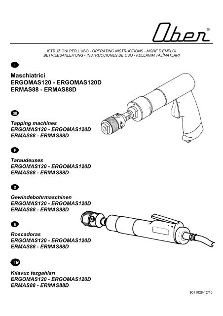
Maschiatrici<br />
ERGOMAS120 - ERGOMAS120D<br />
ERMAS88 - ERMAS88D<br />
GB<br />
Tapping machines<br />
ERGOMAS120 - ERGOMAS120D<br />
ERMAS88 - ERMAS88D<br />
F<br />
Taraudeuses<br />
ERGOMAS120 - ERGOMAS120D<br />
ERMAS88 - ERMAS88D<br />
D<br />
Gewindebohrmaschinen<br />
ERGOMAS120 - ERGOMAS120D<br />
ERMAS88 - ERMAS88D<br />
E<br />
Roscadoras<br />
ERGOMAS120 - ERGOMAS120D<br />
ERMAS88 - ERMAS88D<br />
Kılavuz tezgahları<br />
ERGOMAS120 - ERGOMAS120D<br />
ERMAS88 - ERMAS88D<br />
9011028-12/10
GARANZIA<br />
<strong>Ober</strong> S.p.A. garantisce i propri prodotti per un periodo di dodici mesi dalla data di acquisto e tale garanzia comprende la<br />
riparazione e la sostituzione delle parti che presentano difetti di lavorazione o vizi di materiale ed è riconosciuta solo ai<br />
prodotti inviati o presentati, ai Centri Assistenza Autorizzati, ai rivenditori o direttamente in <strong>Ober</strong>, completi e non<br />
manomessi, sono escluse le parti di ricambio singole danneggiate.<br />
Il prodotto deve essere accompagnato da un documento fiscale comprovante la data di acquisto (scontrino fiscale, fattura<br />
o bolla di consegna).<br />
Sono esclusi dalla garanzia i prodotti già riparati da persone non autorizzate, manomessi o modificati arbitrariamente ed<br />
inoltre gli eventuali danni derivanti da cattiva installazione, uso e manutenzione.<br />
Sono anche escluse dalla garanzia tutte le parti che presentano normale usura e quelle di ordinaria manutenzione.<br />
L’eventuale utilizzo di parti di ricambio non originali <strong>Ober</strong> possono danneggiare l’utensile o ridurne le prestazione e fa<br />
decadere il diritto di garanzia.<br />
WARRANTY<br />
<strong>Ober</strong> S.p.A. guarantees its products for a period of twelve months from the data of purchase. The guarantee covers the<br />
repair and substitution of parts with machining or material defects. The guarantee is only valid if the products are<br />
dispatched or brought to an Authorised Assistance Centre, agent or <strong>Ober</strong> S.p.A. The products must not be tampered with<br />
and they must be complete. Damaged individual spare parts are not covered by the guarantee.<br />
The product must be accompanied by a document to prove the date of purchase (receipt, invoice or delivery note).<br />
Products that have been tampered with or repaired by unauthorised personnel are not covered by the guarantee. Damage<br />
caused by incorrect installation, use or maintenance is also excluded from the guarantee.<br />
Routine maintenance and normal wear are not covered by the guarantee.<br />
The use of spare parts other than original <strong>Ober</strong> ones can damage tools and reduce performance levels. Such action will<br />
also cause the guarantee to be declared null and void.<br />
GARANTIE<br />
<strong>Ober</strong> S.p.A. garantit ses produits pour une période de douze mois à partir de la date d'achat ; cette garantie comprend la<br />
réparation et le remplacement des parties qui présentent des vices de fabrication ou des défauts de matériau et n'est<br />
reconnue que sur les produits envoyés ou apportés aux Centres d'Assistance Autorisés ou directement chez <strong>Ober</strong>,<br />
complets et inaltérés ; la garantie ne comprend pas les pièces détachées abîmées.<br />
Le produit doit être accompagné d'un document fiscal attestant la date d'achat (ticket de caisse, facture ou bulletin de<br />
livraison).<br />
La garantie ne comprend pas les produits déjà réparés par des personnes non autorisées, altérés ou modifiés de manière<br />
arbitraire ainsi que les dommages dus à des erreurs d'installation, d'utilisation et d'entretien.<br />
Sont également exclues de la garantie les pièces d'usure et celles qui doivent être régulièrement remplacées.<br />
L'emploi de pièces détachées non d'origine <strong>Ober</strong> peut endommager l'outil ou en limiter les performances et annule le droit<br />
de garantie.<br />
GARANTIE<br />
<strong>Ober</strong> S.p.A. gewährt für die Produkte eigener Herstellung zwölf Monate Garantie ab Kaufdatum. Die Garantie umfasst die<br />
Reparatur bzw. den Austausch der Teile, die Verarbeitungs- oder Materialfehler aufweisen. Der Garantieanspruch gilt nur<br />
für Produkte, die vollständig und ohne unzulässigen Änderungen an autorisierte Kundendienststellen, an Händler oder<br />
direkt an <strong>Ober</strong> gesandt oder bei diesen eingereicht werden. Einzelne beschädigte Ersatzteile sind von der Garantie<br />
ausgeschlossen.<br />
Das Produkt muss stets von einem Kaufbeleg mit dem Kaufdatum begleitet sein (Kassenzettel, Rechnung oder<br />
Lieferschein).<br />
Von der Garantie ausgeschlossen sind bereits von nicht befugten Personen reparierte und geänderte Produkte sowie<br />
Schäden infolge von unsachgemässer Montage, Verwendung und Wartung.<br />
Von der Garantie ausgeschlossen sind ferner Verschleissteile und Teile, die für die normale Instandhaltung erforderlich<br />
sind.<br />
Die Verwendung von nicht originalen Ersatzteilen kann zur Beschädigung des Werkzeugs führen bzw. dessen Leistung<br />
mindern und führt zum Verfall der Garantie.<br />
GARANTÍA<br />
<strong>Ober</strong> S.p.A. garantiza sus propios productos por un periodo de doce meses a partir de la fecha de compra y dicha<br />
garantía incluye la reparación y la sustitución de las partes que presentan fallas de fabricación o defectos del material y<br />
se reconoce sólo a los productos que se envíen o presenten, en los Centros de Asistencia Autorizados, a los<br />
revendedores o directamente a <strong>Ober</strong>, completos y que no estén forzados, se excluyen las piezas de repuesto separadas<br />
y estropeadas.<br />
El producto debe estar acompañado por un documento fiscal que compruebe la fecha de compra (recibo fiscal, factura o<br />
albarán).<br />
Se excluyen de la garantía los productos ya reparados por personal no autorizado, alterados o modificados<br />
arbitrariamente y además los posibles daños provocados por instalación, uso y mantenimiento inadecuados.<br />
Se excluyen también de la garantía todas las piezas que presentan normal desgaste y las de mantenimiento ordinario.<br />
El uso eventual de piezas de repuesto no originales <strong>Ober</strong> puede provocar daños a la herramienta o reducir su prestación<br />
y en tal caso caduca el derecho de garantía.
GARANTİ<br />
<strong>Ober</strong> S.p.A., ürünleri, satın alınma tarihinden itibaren on iki ay süreyle garanti kapsamındadır. Bu garanti, çalışma<br />
mekanizması veya malzeme kusurlarının onarılmasını ve bozuk parçaların değiştirilmesini kapsar. Bu garanti, sadece<br />
Yetkili Yardım Merkezi, bayiler veya <strong>Ober</strong> S.p.A. tarafından gönderilmiş veya buralardan satın alınmış ürünler için<br />
geçerlidir. Bu ürünler değiştirilmemeli ve eksiksiz olmalıdır. Hasarlı tüm yedek parçaların değişimi garanti kapsamında<br />
değildir.<br />
Ürün ile birlikte satın alım tarihini ispatlayan bir belge (makbuz, fatura veya sevk irsaliyesi) ibraz edilmelidir.<br />
Üzerinde değişiklik yapılan veya yetkili olmayan personel tarafından onarılan ürünler, garanti kapsamında değildir. Ayrıca,<br />
hatalı montaj, kullanım veya bakımdan kaynaklanan hasarlar da garanti kapsamı dışındadır.<br />
Rutin bakım ve normal yıpranma, garanti kapsamı dışındadır.<br />
Orijinal <strong>Ober</strong> yedek parçalarından farklı yedek parçaların kullanılması, araçlara hasar verebilir ve performans seviyelerini<br />
düşürebilir. Bu tür işlemler sonucunda da garanti geçersiz olacaktır.<br />
1
INDICE I<br />
2<br />
Parti principali .................................................................................................................................................... pag. 3<br />
Caratteristiche tecniche .................................................................................................................................... pag. 6<br />
Alimentazione .................................................................................................................................................... pag. 13<br />
Utilizzo ............................................................................................................................................................... pag. 18<br />
Manutenzione .................................................................................................................................................... pag. 27<br />
Accessori .......................................................................................................................................................... pag. 29<br />
CONTENTS<br />
Main components ................................................................................................................................................ pg. 4<br />
Technical features ............................................................................................................................................... pg. 7<br />
Compressed air supply system ........................................................................................................................... pg. 14<br />
Use ...................................................................................................................................................................... pg. 19<br />
Maintenance ........................................................................................................................................................ pg. 27<br />
Accessories ......................................................................................................................................................... pg. 30<br />
INDEX F<br />
Parties principales ............................................................................................................................................ page 4<br />
Caractéristiques techniques ............................................................................................................................. page 8<br />
Alimentation ..................................................................................................................................................... page 14<br />
Utilisation .......................................................................................................................................................... page 19<br />
Entretien ........................................................................................................................................................... page 27<br />
Accessoires ...................................................................................................................................................... page 30<br />
INHALTSVERZEICHNIS D<br />
Hauptteile .............................................................................................................................................................. s. 4<br />
Technische Eigenschaften .................................................................................................................................... s. 9<br />
Druckluftanschluss ................................................................................................................................................ s. 13<br />
Anwendung ........................................................................................................................................................... s. 19<br />
Wartung ................................................................................................................................................................ s. 28<br />
Zubehör ................................................................................................................................................................. s. 30<br />
ÍNDICE E<br />
Partes principales ............................................................................................................................................. pág. 4<br />
Características técnicas .................................................................................................................................... pág. 10<br />
Alimentación ...................................................................................................................................................... pág. 15<br />
Uso .................................................................................................................................................................... pág. 19<br />
Mantenimiento ................................................................................................................................................... pág. 28<br />
Accesorios ........................................................................................................................................................ pág. 30<br />
İÇİNDEKİLER<br />
Ana Bileşenler ................................................................................................................................................. sayfa 4<br />
Teknik özellikler ............................................................................................................................................... sayfa 11<br />
Basınçlı hava besleme sistemi ....................................................................................................................... sayfa 15<br />
Kullanım .......................................................................................................................................................... sayfa 19<br />
Bakım .............................................................................................................................................................. sayfa 28<br />
Aksesuarlar ..................................................................................................................................................... sayfa 30<br />
GB
PARTI PRINCIPALI I<br />
A)....................................................................................................................................................................... Mandrino<br />
B)......................................................................................................................................................... Gruppo invertitore<br />
C) ........................................................................................................................................................... Gruppo riduttore<br />
D) ...................................................................................................................................................... Leva di avviamento<br />
E).................................................................................................................................................. Corpo esterno utensile<br />
F) ................................................................................................................................................................... Silenziatore<br />
G) ............................................................................................................................................... Attacco aria compressa<br />
ERGOMAS120D L= 350 mm H= 54 mm<br />
ERMAS88D L= 340 mm H= 52 mm<br />
ERMAS88 L= 264 mm H= 151 mm<br />
ERGOMAS120 L= 274 mm H= 151 mm<br />
3
MAIN COMPONENTS<br />
4<br />
A)............................................................................................................................................................................ Chuck<br />
B)............................................................................................................................................................. Reversing gear<br />
C) .............................................................................................................................................................. Reduction unit<br />
D) ................................................................................................................................................................ Starting lever<br />
E)...................................................................................................................................................................... Tool body<br />
F) ......................................................................................................................................................................... Silencer<br />
G) .................................................................................................................................................... Compressed air inlet<br />
PARTIES PRINCIPALES F<br />
A)......................................................................................................................................................................... Mandrin<br />
B).......................................................................................................................................................... Groupe inverseur<br />
C) .........................................................................................................................................................Groupe réducteur<br />
D) .............................................................................................................................................. Bouton de mise en route<br />
E)............................................................................................................................................... Corps extérieur de l'outil<br />
F) ..................................................................................................................................................................... Silencieux<br />
G) ................................................................................................................................ Orifice alimentation air comprimé<br />
HAUPTTEILE D<br />
A)...................................................................................................................................................................... Bohrfutter<br />
B)............................................................................................................................................................. Wendegetriebe<br />
C) ................................................................................................................................................. Untersetzungsgetriebe<br />
D) ........................................................................................................................................................................ Schalter<br />
E)........................................................................................................................................................ Werkzeuggehäuse<br />
F) ............................................................................................................................................................... Schalldämpfer<br />
G) ...................................................................................................................................................... Druckluftanschluss<br />
PARTES PRINCIPALES E<br />
A).......................................................................................................................................................................... Mandril<br />
B).............................................................................................................................................................. Grupo inversor<br />
C) .............................................................................................................................................................Grupo reductor<br />
D) .......................................................................................................................................... Leva de puesta en marcha<br />
E)................................................................................................................................ Cuerpo exterior de la herramienta<br />
F) .................................................................................................................................................................... Silenciador<br />
G) ..................................................................................................................................... Conexión del aire comprimido<br />
ANA BİLEŞENLER<br />
A).................................................................................................................................................................. Torna kafası<br />
B).............................................................................................................................................................. Enversör dişlisi<br />
C) ....................................................................................................................................................... Redüksiyon ünitesi<br />
D) ............................................................................................................................................................. Çalıştırma kolu<br />
E).................................................................................................................................................................. Alet gövdesi<br />
F) ...................................................................................................................................................................... Susturucu<br />
G) ....................................................................................................................................................... Basınçlı hava girişi<br />
GB
I<br />
L’operatore dovrà avere letto attentamente e compreso le presenti istruzioni, prima di utilizzare la<br />
macchina. La macchina, i collegamenti e gli accessori devono essere impiegati esclusivamente per lo<br />
scopo espressamente indicato. Qualsiasi modifica alla macchina ed ai suoi accessori deve essere<br />
espressamente autorizzata dall’ufficio tecnico della ditta costruttrice.<br />
Prima di eseguire qualsiasi operazione di manutenzione, registrazione, o non rientrante nel normale<br />
ciclo di funzionamento, escludere il collegamento alla rete di alimentazione.<br />
GB<br />
The operator must read and fully understand these instructions before using the machine. The<br />
machine, connections and accessories must only be used for the purpose specified. Any adjustments<br />
to the motor and accessories must only be done after permission has been granted from the<br />
manufacturer's technical department.<br />
The mains supply must be disconnected before any maintenance, adjustments or non-standard functioning<br />
cycles are undertaken.<br />
F<br />
Avant d'utiliser la machine, l'opérateur doit avoir lu avec attention les présentes instructions et les<br />
avoir assimilées. La machine, les branchements et les accessoires ne doivent être utilisés que pour le<br />
but expressément indiqué. Toute modification apportée à la machine et à ses accessoires doit être<br />
expressément autorisée par le bureau technique du fabricant.<br />
Avant d'effectuer toutes opérations d’entretien et de réglage ou des opérations non comprises dans le cycle<br />
de fonctionnement normal, débrancher le réseau d'alimentation.<br />
D Der Benutzer muss vor Verwendung des Geräts diese Anleitung aufmerksam gelesen und verstanden<br />
haben. Das Gerät, die Anschlüsse und das Zubehör dürfen nur für den ausdrücklich angegebenen<br />
Zweck verwendet werden. Änderungen am Gerät und dessen Zubehör erfordern einer ausdrücklichen<br />
Genehmigung durch die technische Abteilung der Herstellerfirma.<br />
Vor allen Wartungsarbeiten, Einstellungen bzw. sonstigen Arbeiten, die nicht zum normalen Betriebszyklus<br />
zählen, muss der Anschluss an das Versorgungsnetz unterbrochen werden.<br />
E<br />
EI operador tendrá que leer atentamente y entender las presentes instrucciones antes de utilizar<br />
esta máquina. La máquina, las conexiones y los accesorios se deben emplear exclusivamente para<br />
el fin específico indicado. Cualquier modificación de la máquina y de sus accesorios debe estar<br />
especialmente autorizada por el Departamento Técnico de la empresa fabricante. Antes de efectuar<br />
cualquier operación de mantenimiento, regulación, o que no esté incluida en et ciclo de<br />
funcionamiento normal, desconectar la conexión a la red de alimentación.<br />
Operatör, motoru kullanmadan önce bu talimatları okumalı ve tamamen anlamalıdır. Motor, bağlantılar<br />
ve aksesuarlar sadece belirlenen amaç için kullanılmalıdır. Motor ve aksesuarlarda yapılacak herhangi<br />
bir ayarlama, üretici firmanın teknik departmanının onayı alındıktan sonra yapılmalıdır.<br />
Herhangi bir bakım, ayarlama veya standart dışı çalışma yapılmadan önce motorun ana şebekeyle<br />
olan bağlantısı kesilmelidir.<br />
5
CARATTERISTICHE TECNICHE I<br />
Tabella 1<br />
Modello Codice Velocità Potenza Coppia Maschiatura Consumo Peso Rumorosità Vibrazioni Ø int.tubo<br />
(giri/min.) (watt) (Nm) (mm) (Nl/min.) (Kg)<br />
Lp<br />
(dB(A))<br />
ah<br />
(m/s 2 ) (mm)<br />
ERMAS88 8306035 370/740 150 14 8 450 1.35 75,8 < 2,5 6<br />
ERGOMAS120 8306048 360/720 300 28 12 650 1.45 76,6 < 2,5 8<br />
ERMAS88D 8305544 370/740 150 14 8 260 1.39 71,5 < 2,5 6<br />
ERGOMAS120D 8305557 360/720 300 28 12 430 1.55 84,7 < 2,5 8<br />
Attacco aria 1/4 GAS –Attacco mandrino B10<br />
Livello di rumorosità determinato secondo ISO/CD 15744 – ISO 3477<br />
Livello di vibrazioni sull’impugnatura determinato secondo ISO 8662<br />
I modelli ERMAS88/88D - ERGOMAS120/120D sono corredati di mandrino universale cod.7620006 o di mandrino a<br />
cambio rapido cod.7620005 a richiesta.<br />
Avvertenza: verificare che le prestazioni richieste rientrino nel campo di quelle disponibili, in caso contrario occorrerà<br />
scegliere un modello diverso nell'ampia gamma proposta da OBER.<br />
RUMOROSITÀ DELL’UTENSILE<br />
La tabella delle caratteristiche tecniche riporta il livello di pressione sonora (e di potenza acustica, nel caso in cui questo<br />
superi gli 85 db(A)). Le protezioni per l’udito devono essere utilizzate qualora il livello di pressione sonora in posizione<br />
operatore superi gli 85 dB(A) e sono consigliate per valori inferiori a tale soglia.<br />
Il rischio rumore è legato, oltre che all’intensità della sorgente, anche al tempo di esposizione ed è quindi opportuno<br />
valutare l’impiego del singolo utensile nel corso della giornata lavorativa ed attenersi alle disposizioni vigenti nei singoli<br />
Paesi al fine di salvaguardare gli utilizzatori.<br />
La formula e la tabella seguenti consentono di apprezzare l’influenza del tempo di utilizzo sul livello di esposizione<br />
giornaliera, grazie al coefficiente di impiego c, che per le maschiatrici è compreso tra il 20 ed il 40%.<br />
6<br />
Livello esposizione<br />
giornaliera<br />
Leq,d = Leq + 10 Log10 Te/ T0<br />
VIBRAZIONI DELL’UTENSILE<br />
L’utensile in oggetto, provato nel rispetto delle condizioni imposte dalle norme tecniche di riferimento<br />
per la pressione di alimentazione:<br />
ISO 2787 (Rotary and percussive pneumatic tools – performance tests)<br />
per le indicazioni generali di prova:<br />
ISO 8662 (Hand-held portable power tools – Measurement of vibration at the handle) recepita dalla UNI EN 28662<br />
per i fattori di ponderazione:<br />
ISO 5349 (Mechanical vibration - Guidelines for the measurements and the assessments of human exposure to<br />
hand-trasmitted vibration<br />
è caratterizzato dal seguente livello di vibrazioni:<br />
Te= c T0<br />
T0 = 8h<br />
ah = accelerazione ponderata in frequenza
TECHNICAL FEATURES<br />
Table 1<br />
Model Code N° Speed Power Torque Tapping Consumption Weight Noise<br />
Lp<br />
Vibrations<br />
ah<br />
GB<br />
Ø inside tube<br />
(rpm) (watt) (Nm) (mm) (Nl/min.) (Kg) (dB(A)) (m/s 2 ) min.mm<br />
ERMAS88 8306035 370/740 150 14 8 450 1.35 75,8 < 2,5 6<br />
ERGOMAS120 8306048 360/720 300 28 12 650 1.45 76,6 < 2,5 8<br />
ERMAS88D 8305544 370/740 150 14 8 260 1.39 71,5 < 2,5 6<br />
ERGOMAS120D 8305557 360/720 300 28 12 430 1.55 84,7 < 2,5 8<br />
Air inlet 1/4 GAS – Chuck connection: B10<br />
Noise emission levels determined by using ISO/CD 15744 – ISO 3477<br />
Levels of vibrations at the handle determined by using ISO 8662<br />
The ERMAS88/88D - ERGOMAS120/120D models are supplied with the universal chuck, code n°7620006 or the quickrelease<br />
chuck, code n° 7620005, on request.<br />
NOTE: make sure that the performance features required correspond to those described above, otherwise it will be<br />
necessary to choose a different model from the broad range offered by OBER.<br />
TOOL NOISE<br />
The table of technical specifications indicates the noise level- where the noise level exceeds 85 dB (A) the noise power is<br />
also indicated. Ear protectors must be worn where the noise level exceeds 85 dB (A) at the operator position. We<br />
recommend that you also wear ear protectors below this noise level.<br />
Noise risk and hearing damage are related to the intensity of the noise source and the length of exposure. Noise risk must<br />
be assessed on a case by case basis taking into account these two factors. Measures should be taken to protect the user<br />
against hearing damage in accordance with current Health and Safety regulations.<br />
The formula and table can be used to calculate the daily exposure level for a tool using the use coefficient c. The use<br />
coefficient c for tapping machines is between 20 and 40%.<br />
TOOL VIBRATION<br />
Daily exposure<br />
level<br />
Leq,d = Leq + 10 Log10 Te/ T0<br />
The tool in question, tested with regard to the conditions required by the relevant technical standards for feed pressure:<br />
ISO 2787 (Rotary and percussive pneumatic tools - performance tests)<br />
for general test indications:<br />
ISO 5349 (Mechanical vibration - Guidelines for the measurements and the assessments of human exposure to<br />
hand-transmitted vibration<br />
for weighting factors:<br />
ISO 5349 (Mechanical vibration - Guidelines for the measurements and the assessments of human exposure to<br />
hand-transmitted vibration<br />
characterised by the following level of vibrations:<br />
Te= c T0<br />
T0 = 8h<br />
ah = frequency-weighted acceleration
CARACTERISTIQUES TECHNIQUES F<br />
Tableau 1<br />
Modèle Code Vitesse Puissance Couple Taraudage Consomm. Poids Bruit Lp Vibration ah Øint.tube<br />
(tour/min) (watt) (Nm) (mm) (Nl/min.) (Kg) (dB(A)) (m/s 2 ) min.mm<br />
ERMAS88 8306035 370/740 150 14 8 450 1.35 75,8 < 2,5 6<br />
ERGOMAS120 8306048 360/720 300 28 12 650 1.45 76,6 < 2,5 8<br />
ERMAS88D 8305544 370/740 150 14 8 260 1.39 71,5 < 2,5 6<br />
ERGOMAS120D 8305557 360/720 300 28 12 430 1.55 84,7 < 2,5 8<br />
Orifice alimentation air 1/4 GAZ – Emmanchement: B10<br />
Niveau sonore déterminé selon les normes ISO/CD 15744 – ISO 3477;<br />
Niveau des vibrations sur la poigneé déterminé selon les normes ISO 8662<br />
Les modèles ERMAS88/88D - ERGOMAS120/120D sont équipés de mandrin universel code 7620006 ou de mandrin à<br />
changement rapide code 7620005 sur demande.<br />
ATTENTION: vérifiez que les caracteristiques requises correspondent aux possibilités de l’outil; sinon il conviendra de<br />
choisir un modèle différent parmi tous ceux de la gamme OBER.<br />
BRUIT DE L'OUTIL<br />
Le tableau des caractéristiques techniques indique le niveau de pression sonore (et de puissance acoustique, si celle-ci<br />
dépasse les 85 db(A)). Les protections pour l'appareil auditif doivent être utilisées lorsque le niveau de pression sonore<br />
sur le poste de l'opérateur dépasse les 85 dB(A) et elles sont recommandées pour des valeurs inférieures à ce seuil.<br />
Le risque sonore est lié, outre à l'intensité de la source, à la durée d’exposition. Il convient donc d’évaluer l'utilisation de<br />
chaque outil dans la journée de travail et de respecter les dispositions en vigueur dans les différents pays afin de protéger<br />
les utilisateurs.<br />
La formule et les tableaux suivants permettent d’apprécier l'influence de la durée d'utilisation sur le niveau d'exposition<br />
quotidienne, grâce au coefficient d'utilisation c, qui, pour les taraudeuses, est compris entre 20 et 40%,<br />
8<br />
Niveau d'exposition<br />
Journalière<br />
Leq,d = Leq + 10 Log10 Te/ T0<br />
VIBRATIONS DE L'OUTIL<br />
Le présent outil, testé conformément aux conditions prescrites par les normes techniques de référence<br />
pour la pression d’alimentation:<br />
ISO 2787 (Outils pneumatiques rotatifs et à percussion – essais de performances)<br />
pour les indications générales d’essai:<br />
ISO 5349 (Vibrations mécaniques – Directives pour la mesure et l’évaluation de l’exposition de l’homme à des<br />
vibrations transmises par les mains)<br />
pour les facteurs de pondération:<br />
ISO 5349 (Vibrations mécaniques – Directives pour la mesure et l’évaluation de l’exposition de l’homme à des<br />
vibrations transmises par les mains)<br />
présente le niveau de vibrations suivant:<br />
ah = accélération pondérée en fréquence
TECHNISCHE EIGENSCHAFTEN D<br />
Tabelle 1<br />
Modell Kode Geschwi<br />
Leistung DrehGewinde- Verbrauch Gewicht Lärm Vibrationen<br />
n-digkeit<br />
(U/min.) (watt)<br />
moment<br />
(Nm)<br />
bohren<br />
(mm) (Nl/min.) (Kg)<br />
Lp<br />
(dB(A))<br />
ah<br />
(m/s 2 ) (mm)<br />
ERMAS88 8306035 370/740 150 14 8 450 1.35 75,8 < 2,5 6<br />
ERGOMAS120 8306048 360/720 300 28 12 650 1.45 76,6 < 2,5 8<br />
Schlauchdurchm.<br />
innen Ø min.<br />
ERMAS88D 8305544 370/740 150 14 8 260 1.39 71,5 < 2,5 6<br />
ERGOMAS120D 8305557 360/720 300 28 12 430 1.55 84,7 < 2,5 8<br />
Druckluftanschluß 1/4 GAS – Kupplung: B10<br />
Geräuschpegel gemessen nach ISO/CD 15744 – ISO 3477<br />
Schwingungspegel am Handgriff gemessen nach ISO 8662<br />
Die Modelle ERAMAS88/88D - ERGOMAS120/120D sind wahlweise mit Universalbohrfutter Kenn-Nr. 7620006 oder mit<br />
Schnellwechselfutter Kenn-Nr. 7620005 ausgestattet.<br />
ACHTUNG: Kontrollieren, ob die gewünschten Anwendungen geleistet werden können, andernfalls soll ein anderes<br />
Modell aus der grossen Produktpalette der Firma OBER gewählt werden.<br />
LARMEMISSION DES WERKZEUGS<br />
In der Tabelle der Technischen Eigenschaften ist der Schalldruckpegel (bei Überschreiten von 85 dB(A) auch der<br />
Schalleistungspegel) angegeben. Das Tragen eines Gehörschutzes ist vorgeschrieben, wenn der Schalldruckpegel am<br />
Bedienerstand 85 dB(A) überschreitet, und wird bei Werten unterhalb dieser Grenze empfohlen.<br />
Die Gefährdung durch Lärmbelastung hängt nicht allein von der Emissionsstärke an der Quelle ab, sondern auch von der<br />
Aussetzungsdauer. Daher empfiehlt sich eine Beurteilung des über den Arbeitstag verteilten Einsatzes des einzelnen<br />
Werkzeuges. In jedem Fall sind die im jeweiligen Land geltenden Bestimmungen zum Schutz des Bedienungspersonals<br />
einzuhalten.<br />
Die folgende Formel und Tabelle ermöglichen, dank des Nutzungskoeffizienten, der bei Gewindebohrmaschine zwischen<br />
20 und 40% liegt, eine Beurteilung der Auswirkung der Einsatzdauer auf den täglichen Belastungspegel,<br />
Täglicher<br />
Belastungspegel<br />
Leq,d = Leq + 10 Log10 Te/ T0<br />
MECHANISCHE SCHWINGUNGEN DES WERKZEUGS<br />
e= c T0<br />
T0 = 8h<br />
Leq c Leq,d<br />
85 20%<br />
30%<br />
40%<br />
Das betreffende Werkzeug, geprüft nach Vorgabe der von den einschlägigen technischen Normen vorgeschriebenen<br />
Bedingungen<br />
für den Versorgungsdruck:<br />
ISO 2787 (Pneumatische Druck- und Schlagwerkzeuge - Leistungsprüfungen)<br />
für die allgemeinen Prüfanweisungen:<br />
ISO 5349 (Mechanische Schwingungen - Messung und Bewertung der Einwirkung von Schwingungen auf das<br />
Hand-Arm-System des Menschen)<br />
für die Gewichtungsfaktoren:<br />
ISO 5349 (Mechanische Schwingungen - Messung und Bewertung der Einwirkung von Schwingungen auf das<br />
Hand-Arm-System des Menschen)<br />
ist durch folgenden Vibrationspegel gekennzeichnet:<br />
ah = frequenzbewertete Beschleunigung
CARACTERISTICAS TECNICAS E<br />
Tabla 1<br />
Modelo Código Velocidad Potencia Par Aterrajadura Consumo Peso Ruidos<br />
10<br />
Lp<br />
Vibraciones<br />
ah<br />
Ø int.tubo<br />
(rpm) (watt) (Nm) (mm) (Nl/min.) (Kg) (dB(A)) (m/s 2 ) min. (mm)<br />
ERMAS88 8306035 370/740 150 14 8 450 1.35 75,8 < 2,5 6<br />
ERGOMAS120 8306048 360/720 300 28 12 650 1.45 76,6 < 2,5 8<br />
ERMAS88D 8305544 370/740 150 14 8 260 1.39 71,5 < 2,5 6<br />
ERGOMAS120D 8305557 360/720 300 28 12 430 1.55 84,7 < 2,5 8<br />
Conexión aire1/4 GAS – Ø int. tubo min.8 mm. – Conexión: B10<br />
Nivel del ruido determinado según ISO/CD 15744 – ISO 3477<br />
Nivel de vibraciones en la empuñadura determinado según ISO 8662<br />
Los modelos ERMAS88/88D - ERGOMAS120/120D están provistos de mandril universal cód. 7620006 o de mandril de<br />
cambio rápido cód. 7620005 bajo pedido.<br />
ADVERTENCIA: controlar que las prestaciones requeridas se encuentren dentro del campo de las disponibles; en caso<br />
contrario, escoger otro modelo de la amplia gama propuesta por OBER.<br />
RUIDO DE LA HERRAMIENTA<br />
La tabla de las características técnicas detalla el nivel de presión sonora (y de potencia acústica, en el caso en que la<br />
misma supere los 85 dB(A). Las protecciones para el oído se deben utilizar cada vez que el nivel de presión sonora en la<br />
posición del operador supere los 85 dB(A), se aconsejan también para valores inferiores a dicho limite.<br />
El peligro del ruido, además de estar relacionado con la intensidad de la fuente, depende también del tiempo de<br />
exposición y es conveniente, por lo tanto, tener en cuenta el empleo de cada herramienta durante la jornada de trabajo y<br />
atenerse a las normas vigentes en su País, para salvaguardar a los usuarios.<br />
La fórmula y la tabla siguientes permiten apreciar la influencia del tiempo de uso según el nivel de exposición por dia;<br />
gracias al coeficiente de empleo c, que para las roscardoras está comprendido entre el 10 y el 35%.<br />
Nivel de exposición<br />
por día<br />
VIBRACIONES DE LA HERRAMIENTA<br />
Leq,d = Leq + 10 Log10 Te/ T0<br />
e= c T0<br />
T0 = 8h<br />
Esta herramienta ensayada en cumplimiento de las condiciones previstas por las normas técnicas de referencia<br />
por lo que concierne a la presión de alimentación:<br />
ISO 2787 (Rotary and percussive pneumatic tools - performance tests)<br />
por lo que concierne a las indicaciones generales de ensayo:<br />
ISO 5349 (Mechanical vibration - Guidelines for the measurements and the assessments of human exposure to<br />
hand-trasmitted vibration<br />
por lo que concierne a los factores de ponderación:<br />
ISO 5349 (Mechanical vibration - Guidelines for the measurements and the assessments of human exposure to<br />
hand-trasmitted vibration<br />
se caracteriza por el siguiente nivel de vibraciones:<br />
ah = aceleración ponderada en frecuencia
TEKNİK ÖZELLİKLER<br />
Tablo 1<br />
Model<br />
Kod Devir Güç Tork<br />
Kilavuz<br />
çekme<br />
Hava<br />
Tüketim<br />
Ağırlık<br />
Gürültü<br />
Lp<br />
Titreşim<br />
ah<br />
Iç tüp çapı<br />
(dev/dak) (W) (Nm) (mm) (Nl/dak.) (Kg) (dB(A)) (m/s 2 ) Ø min.mm<br />
ERMAS88 8306035 370/740 150 14 8 450 1.35 75,8 < 2,5 6<br />
ERGOMAS120 8306048 360/720 300 28 12 650 1.45 76,6 < 2,5 8<br />
ERMAS88D 8305544 370/740 150 14 8 260 1.39 71,5 < 2,5 6<br />
ERGOMAS120D 8305557 360/720 300 28 12 430 1.55 84,7 < 2,5 8<br />
Hava girişi 1/4 BENZİNLİ - Torna kafası bağlantısı: B10<br />
Gürültü emisyon seviyeleri ISO/CD 15 744 – ISO 3477 kullanılarak belirlenmiştir<br />
Saptaki titreşim seviyesi ISO 8662 kullanılarak belirlenmiştir<br />
ERMAS88/88D - ERGOMAS120/120D modellerinde 7620006 kod numaralı üniversal torna kafası veya talep üzerine<br />
7620005 kod numaralı hızlı çıkarılır torna kafası bulunabilir.<br />
NOT: gereken performans özellikleri ile yukarıda açıklananların aynı olduğundan emin olun; eğer değilse OBER tarafından<br />
sunulan kapsamlı yelpazeden bir başka model seçmeniz gerekecektir.<br />
ALET GÜRÜLTÜ SEVİYESİ<br />
The table of technical specifications indicates the noise level- where the noise level exceeds 85 dB (A) the noise power is<br />
also indicated. Ear protectors must be worn where the noise level exceeds 85 dB (A) at the operator position. We<br />
recommend that you also wear ear protectors below this noise level.<br />
Noise risk and hearing damage are related to the intensity of the noise source and the length of exposure. Noise risk must<br />
be assessed on a case by case basis taking into account these two factors. Measures should be taken against hearing<br />
damage in accordance with current Health and Safety regulations.<br />
Bir alet için günlük maruz kalma seviyesi, c kullanım katsayısı kullanılarak ve formül ve tablo yardımıyla hesaplanabilir.<br />
Kılavuz tezgahları için c kullanım katsayısı %20 - %40 arasındadır.<br />
Günlük maruz<br />
kalma seviyesi<br />
TOPLAM TİTREŞİM<br />
Leq,d = Leq + 10 Log10 Te/ T0<br />
Söz konusu alet, ilgili besleme basıncı teknik standartları tarafından gerekli kılınan koşullara göre test edilmiştir:<br />
ISO 2787 (Döner ve darbeli pnömatik aletler - performans testleri)<br />
genel test göstergeleri için:<br />
ISO 5349 (Mekanik titreşim - El üzerinden aktarılan titreşim için maruz kalma seviyelerinin ölçümü ve<br />
değerlendirmesi için yönergeler<br />
ağırlık faktörleri için:<br />
ISO 5349 (Mekanik titreşim - El üzerinden aktarılan titreşim için maruz kalma seviyelerinin ölçümü ve<br />
değerlendirmesi için yönergeler<br />
aşağıdaki titreşim seviyelerine sahiptir:<br />
Te= c T0<br />
T0 = 8h<br />
ah = frekans ağırlıklı hızlanma
ALIMENTAZIONE I<br />
IMPIANTO<br />
Un buon impianto di alimentazione dell'aria compressa deve fornire all'utenza aria priva di impurità e di condensa,<br />
lubrificata se necessario, ed alla corretta pressione. Devono quindi essere curate le modalità di collegamento dei tubi le<br />
cui dimensioni debbono essere adeguate alla quantità di aria richiesta complessivamente dalle diverse utenze ed alla<br />
lunghezza delle tubazioni stesse. In fig.1 è rappresentato lo schema generale di un impianto correttamente eseguito. Da<br />
notare che raccordi e valvole debbono avere una dimensione minima dei condotti non inferiore a quella dei tubi in cui sono<br />
inseriti.<br />
PRESSIONE DI ALIMENTAZIONE. La pressione all'ingresso dell'utensile deve essere compresa fra 5.5 e 6.5 bar. Valori<br />
inferiori determinano perdite di potenza, valori superiori possono causare danni e comunque abbreviano la vita<br />
dell'utensile.<br />
QUANTITÀ D'ARIA. Vedere tabella 1. Il valore indicato si riferisce al funzionamento continuo. Il funzionamento<br />
intermittente provoca un minor consumo, in relazione al tempo di utilizzo.<br />
TUBO E RACCORDI. Vedere tabella 1. Se la lunghezza supera i 5 m, aumentare il diametro. Usare tubi resistenti all'olio.<br />
Usare raccordi che non creino strozzature al passaggio dell'aria, non utilizzare tubi danneggiati, usurati o deteriorati.<br />
Ispezionare i tubi di alimentazione prima dell’utilizzo.<br />
PULIZIA DELL'ARIA. L'aria deve essere esente da impurità (polvere, acqua di condensa, olio denso, ecc). Usare sempre<br />
un filtro, applicato il più possibile vicino all'utensile. Scaricare il filtro giornalmente.<br />
LUBRIFICAZIONE. Gli utensili OBER funzionano con lubrificazione. Una adeguata lubrificazione, garantita da lubrificatori<br />
a micronebbia, favorisce le prestazioni e la durata dei componenti. Usare soltanto olio speciale per utensili pneumatici<br />
(codice OBER 5989902). Usare preferibilmente lubrificatori automatici. La quantità di olio sufficiente è di 1-2 gocce<br />
giornaliere.<br />
fig.1<br />
I<br />
12<br />
GB<br />
F<br />
D E<br />
1) Compressore 1) Compressor 1) Compresseur 1) Kompressor 1) Compresor 1) Kompresör<br />
2) Tubo principale 2) Main pipe 2) Tuyau principal 2) Hauptschlauch 2) Tubo principal 2) Ana boru<br />
3) Tubo di raccordo 3) Pipe connection 3) Tube de raccord 3) Anschlußschlauch 3) Tubo de empalme 3) Boru bağlantısı<br />
4) Sifone di scarico 4) Exhaust siphon 4) Siphon d'échapp. 4) Abflusssyphon 4) Sifón de descarga 4) Egzoz sifonu<br />
5) Valvola di chiusura 5) Closing valve 5) Soupape d'arrêt 5) Verschlussventil 5) Válvula de cierre 5) Kapatma valfi<br />
6) Filtro 6) Filter 6) Filtre 6) Filter 6) Filtro 6) Filtre<br />
7) Riduttore 7) Reduction unit 7) Réducteur 7) Druckverminderer 7) Reductor 7) Redüksiyon ünitesi<br />
8) Lubrificatore 8) Lubricator 8) Graisseur 8) Schmierung 8) Lubricador 8) Yağlayıcı<br />
9) Tubo motore 9) Motor hose 9) Tube moteur 9) Geräteschlauch 9) Tubo motor 9) Motor hortumu
COMPRESSED AIR SUPPLY SYSTEM<br />
A good compressed air system must supply air that is free from impurities and condensation, lubricated if necessary and<br />
at the correct pressure. Careful attention must therefore be paid to the connection of the pipes and hoses, which must<br />
have dimensions compatible with the overall quantity of air required by each different user and the length of the pipes<br />
themselves. Fig. 1 illustrates the general layout of a system set up correctly. Note that the inside dimensions of<br />
connections and valves must not be smaller than those of the pipes and hoses in which they are inserted.<br />
AIR PRESSURE. The pressure of the compressed air supplied to the motor must be between 5.5 and 6.5 bar. Lower<br />
pressure results in a loss of power, higher pressure may cause damage and in any case shorten the life of the motor.<br />
QUANTITY OF AIR. See table 1. The indicated quantity refers to non-stop operation. Intermittent operation carries lower<br />
consumption levels (proportional to the rime of use).<br />
PIPES, HOSES AND CONNECTIONS. See table 1: If the length exceeds 5 m, increase the diameter. Use oil-resistant<br />
pipes and hoses. Use connections that do not obstruct the passage of air.<br />
CLEANING THE AIR. The air must be free from impurities (dust, condensation, dense oil, etc.). Always use a filter,<br />
placing it as close as possible to the motor. Empty the filter daily.<br />
LUBRICATION. The motors work with lubrication. Proper lubrication enhances the performance of the components and<br />
makes them last longer. Use only special oil for pneumatic motors (OBER code 5989902). We recommend using<br />
automatic lubricators. The sufficient quantity of oil contained in the compressed air is 3-5 mg/m 3 .<br />
ALIMENTATION F<br />
INSTALLATION<br />
Une bonne installation d'alimentation de l'air comprimé doit fournir à l'usager de l'air sans impureté, sans condensation,<br />
lubrifiée en cas de nécessité, et d'une pression correcte. Il convient donc de veiller particulièrement au branchement des<br />
tuyaux, dont les dimensions doivent correspondre à la quantité d'air requise en général par les différents types d'usagers<br />
ainsi qu'à leur longueur. La figure 1 représente le schéma général d'une installation correcte. Observez que la dimension<br />
minimum des gaines de raccords et soupapes ne doit être en aucun cas inférieure à celle des tuyaux où elles sont<br />
insérées.<br />
PRESSION D'ALIMENTATION. A l'entrée du moteur, la pression doit être comprise entre 5.5 et 6.5 bar. Une pression<br />
inférieure entraîne des pertes de puissance; une pression supérieure risque de provoquer des dommages et en tous cas<br />
abrège la vie du moteur.<br />
QUANTITE D'AIR. Voir tableau 1. La valeur indiquée se réfère à un fonctionnement continu du moteur. Un<br />
fonctionnement intermittent entraîne une consommation inférieure en fonction du temps d'utilisation.<br />
TUYAU ET RACCORDS. Voir tableau 1. Si la longueur dépasse 5 mètres, augmentez le diamètre. Utilisez des tuyaux<br />
résistants à l'huile. Utilisez des raccords qui ne créent pas d'étranglement lors du passage de l'air.<br />
PURETE DE L'AIR. L'air doit être sans impureté (poussière, eau de condensation, huile dense, etc.). Utilisez toujours un<br />
filtre, appliqué le plus près possible du moteur. Nettoyez le filtre tous les jours.<br />
GRAISSAGE. Les moteurs fonctionnent s'ils sont graissés. Un graissage approprié favorise les prestations et la durée<br />
des pièces. Utilisez uniquement l'huile spéciale pour moteurs pneumatiques (code OBER 5989902). Utilisez de préférence<br />
des graisseurs automatiques. Il suffit une quantité d’huile contenue dans l’air comprimé de 3-5 mg/m 3 .<br />
DRUCKLUFTANSCHLUSS D<br />
ANLAGE<br />
Dem Nutzgerät muss durch eine gute Anlage für die Druckluftzuführung reine und kondensfreie Luft garantiert werden. Die<br />
Anlage muss bei Bedarf geschmiert werden und den entsprechenden Druck besitzen. Die Bedingungen für den Anschluss<br />
der Schläuche müssen beachtet werden. Die Abmessungen müssen der insgesamt benötigten Luftmenge und der Länge<br />
der Schlauchverbindungen selbst entsprechen, um die angeschlossenen Nutzgeräte zu versorgen. Auf Abb. 1 ist das<br />
allgemeine Schema einer korrekt angeschlossenen Anlage abgebildet. Zu beachten ist, dass die Anschlussstücke und<br />
Ventile einen minimalen Leitungsdurchmesser besitzen müssen, der nicht kleiner als jener der Schläuche ist, in die sie<br />
eingesetzt werden.<br />
ZUGEFÜHRTER DRUCK. Der Druck am Eingang des Motors muss zwischen 5,5 und 6,5 bar betragen. Niedrigere Werte<br />
verursachen einen Leistungsverlust, höhere Werte verursachen Schäden am Werkzeug und in jedem Fall eine geringere<br />
Lebensdauer.<br />
LUFTMENGE. Siehe Tabelle 1. Der angegebene Wert bezieht sich auf einen andauernden Betrieb. Bei punktuellem<br />
Einsatz ist der Verbrauch entsprechend der Einsatzzeit geringer.<br />
SCHLAUCH UND ANSCHLÜSSE. Siehe Tabelle 1. Bei einer Länge über 5 m muss der Durchmesser vergrössert<br />
werden. Ölresistente Schläuche verwenden. Anschlussstücke verwenden, die den Luftfluss nicht beeinträchtigen.<br />
GB<br />
13
LUFTREINIGUNG. Die Luft muss frei von Unreinheiten sein (Staub, Kondenswasser, dickflüssiges Öl, usw.). Immer einen Filter<br />
verwenden, der so nah wie möglich am Motor angebracht sein sollte. Den Filter täglich reinigen.<br />
SCHMIERUNG. Die Motoren funktionieren mit Schmierung. Eine geeignete Schmierung begünstigt die Anwendung und die<br />
Lebensdauer der Teile. Nur Spezialöl für pneumatische Motoren verwenden (Kode OBER 5989902). Vorzugsweise<br />
automatische Schmiergeräte verwenden. Die genügende Menge Öl enthalten in der Druckluft ist 3-5 mg/m 3 .<br />
ALIMENTACIÓN E<br />
INSTALACIÓN<br />
Una buena instalación de aire comprimido tiene que suministrar, al usuario, aire sin impurezas ni condensaciones,<br />
lubricado si es necesario, y a la presión correcta. Por lo tanto, la conexión de los tubos se tiene que realizar con mucho<br />
esmero prestando atención a que las dimensiones de los mismos sean adecuadas a la cantidad de aire requerida por los<br />
diferentes usos y a la longitud de los mismos tubos. En la fig. 1 se ilustra el esquema general de una instalación montada<br />
correctamente. Se recuerda que la dimensión mínima de las conducciones de los empalmes y las válvulas tiene que se<br />
superior a la de los tubos a los que se conectan.<br />
PRESIÓN DE ALIMENTACIÓN. La presión en la entrada del motor tiene que estar comprendida entre 5,5 y 6,5 bar.<br />
Valores inferiores pueden provocar pérdidas de potencia, valores superiores pueden acarrear daños y, en cualquier caso,<br />
disminuir la vida del motor.<br />
CANTIDAD DE AIRE. Ver tabla nº 1. El valor indicado se refiere al funcionamiento continuo. El funcionamiento<br />
intermitente provoca un menor consumo, en relación con el tiempo de uso.<br />
TUBO Y EMPALMES. Ver tabla nº 1. Si la longitud supera los 5 metros, aumentar el diámetro. Usar tubos resistentes al<br />
aceite. Usar empalmes que no estrangulen el paso del aire.<br />
LIMPIEZA DEL AIRE. El aire no debe contener impurezas (polvo, agua de condensación, aceite denso, etc.). Utilizar<br />
siempre un filtro, aplicado lo más cerca posible al motor. Limpiar el filtro diariamente.<br />
LUBRICACIÓN. Los motores funcionan con lubricación. Una lubricación adecuada favorece las prestaciones y la<br />
duración de los componentes. Utilizar solamente aceite especial para motores neumáticos (código OBER 5989902).<br />
Utilizar preferentemente lubricadores automáticos. La cantidad bastante de aceite contenido en el aire comprimido es 3-5<br />
mg/m 3 .<br />
BASINÇLI HAVA BESLEME SİSTEMİ<br />
İyi bir basınçlı hava sistemi, kirlilik ve yoğuşmanın olmadığı temiz hava sağlamalı, gerektiğinde yağlanmalı ve doğru<br />
basınçta tutulmalıdır. Bu nedenle, her bir farklı kullanıcı için gereken toplam hava miktarına ve boruların uzunluklarına<br />
uygun boyutlarda olması gereken boruların ve hortumların bağlantılarına özellikle dikkat edilmelidir. Şekil 1, sistemin doğru<br />
kurulum düzenini gösterir. Bağlantıların ve valflerin iç boyutları, içine yerleştirilecekleri boruların ve hortumların<br />
boyutlarından küçük olmamalıdır.<br />
HAVA BASINCI. Motora sağlanan havanın basıncı 5,5 ve 6,5 bar arasında olmalıdır. Daha düşük basınç güç kaybına,<br />
daha yüksek basınç hasara sebep olabilir ve her iki durumda da motorun kullanım ömrü kısalır.<br />
HAVA MİKTARI. Bkz. tablo 1. Gösterilen miktar, kesintisiz çalışma için geçerli miktardır. Aralıklı çalışmalar için tüketim<br />
seviyeleri daha düşüktür (kullanım süresi ile orantılı olarak).<br />
BORULAR, HORTUMLAR VE BAĞLANTILAR. Bkz. tablo 1: Uzunluk 5 m'den fazlaysa, çapı artırın. Yağ geçirmez<br />
borular ve hortumlar kullanın. Hava geçişine engel olmayacak bağlantılar kullanın.<br />
HAVANIN TEMİZLENMESİ. Havada kirlilik olmamalıdır (toz, yoğuşma, yoğun yağ, vb.). Her zaman filtre kullanın ve filtreyi<br />
motora en yakın konuma yerleştirin. Filtreyi her gün boşaltın.<br />
YAĞLAMA. Motorların çalışması için yağlanması gerekir. Düzgün yağlama, bileşenlerin performansını artırır ve daha uzun<br />
süre kullanılmalarını sağlar. Sadece pnömatik motorlara özel yağ kullanın (OBER kodu 5989902). Otomatik yağlayıcı<br />
kullanmanızı öneririz. Basınçlı havada bulunan yeterli yağ miktarı 3-5 mg/m 3 ' tür.<br />
14
COLLEGAMENTO<br />
1. Togliere il tappo sul raccordo ingresso aria<br />
2. Avvitare un raccordo per il tubo di alimentazione. Assicurarsi che il raccordo ed il tubo abbiano le caratteristiche<br />
indicate in tabella 1 (Nota: la tenuta sul filetto di collegamento dell'utensile-raccordo va assicurata con una buona<br />
guarnizione e non con un serraggio troppo forte)<br />
3. Far uscire aria dal tubo per alcuni secondi per assicurarsi che siano esplulse impurità e condensa che potrebbero<br />
essere all'interno del tubo soprattutto se esso è stato inattivo per qualche tempo<br />
4. Collegare l'utensile<br />
5. Prima di mettere in funzione l’utensile leggere attentamente le presenti istruzioni e quelle del fascicolo per la<br />
sicurezza N. 9011036 che ne costituisce parte integrante.<br />
1<br />
3<br />
4<br />
2<br />
I<br />
15
CONNECTION<br />
1. Remove the cap on the air inlet.<br />
2. Screw in a connection for the hose supplying air. Make sure that the connection and the hose have the features<br />
indicated in table 1 (Note: do not screw in the connection too tightly but secure it by a suitable gasket).<br />
3. Turn on the air supply for a few seconds to allow the expulsion of all impurities and condensation which may have<br />
accumulated inside the hose, especially if it has not been used for some time.<br />
4. Connect the tool.<br />
5. Before switching on the tool, read very carefully these instructions and those in the safety booklet no. 9011036, an<br />
integral part of this.<br />
BRANCHEMENT<br />
1. Otez le bouchon du raccord d'entrée d'air<br />
2. Vissez un raccord pour le tuyau d'alimentation. Veillez à ce que le raccord et le tuyau présentent les<br />
caractéristiques indiquées au tableau 1 (Remarque: Pour vous assurer de la résistance au niveau du filet de l’orifice<br />
de branchement sur l’outil, utilisez un bon joint et ne serrez pas trop fort)<br />
3. Faites sortir l'air par le tuyau pendant quelques secondes pour vous assurer qu'il n'y a plus d'impureté ni d'eau de<br />
condensation à l'intérieur, surtout s'il n'a pas fonctionné depuis longtemps.<br />
4. Branchez l'outil.<br />
5. Avant d’utiliser l’outil, lire attentivement ces instructions et celles contenues dans la brochure de sécurité N.<br />
9011036 qui est partie intégrante du produit.<br />
ANSCHLUSS<br />
1. Pfropfen am Anschluss für die Luftzufuhr abnehmen.<br />
2. Ein Anschlußstück für den Zufuhrschlauch anschrauben. Kontrollieren, ob das Anschlussstück und der Schlauch<br />
den in Tabelle 1 angegebenen Eigenschaften entsprechen (Anmerkung: Die Befestigung auf dem Gewinde des<br />
Werkzeuganschlussstückes wird durch eine gute Dichtung und eine nicht zu streng angezogene Schlauchklemme<br />
gesichert).<br />
3. Luft für einige Sekunden aus dem Schlauch strömen lassen, um alle Unreinheiten und Kondensrückstände zu<br />
vermeiden, die sich im Inneren des Schlauches befinden könnten, vor allem, wenn dieser seit längerer Zeit nicht in<br />
Verwendung war.<br />
4. Das Werkzeug anschliessen<br />
5. Vor inbetriebnahme des gerates lese man diese anweisungen, sowie diejenigen der sicherheitsbroschüre Nr.<br />
9011036 die integrierender bestandteil dieser ausführungen ist, aufmerksam durch.<br />
CONEXIÓN<br />
1. Sacar el tapón en el empalme de la entrada del aire.<br />
2. Enroscar un empalme para el tubo de alimentación. Asegurarse de que el empalme y el tubo posean las<br />
características indicadas en la tabla nº 1 (Nota: la estanqueidad en la rosca de conexión entre la herramienta y el<br />
empalme se asegura mediante una buena junta y no por un apriete demasiado fuerte).<br />
3. Dejar salir el aire del tubo durante unos segundos para asegurarse de que se expulsen todas las impurezas y<br />
condensaciones que podría haber en su interior, sobre todo, si ha permanecido inactivo por un largo periodo.<br />
4 conectar la herramienta.<br />
5. Antes de poner en marcha la herramienta lea con attención las presentes instrucciones y las del fasciculo relativo a<br />
la seguridad N. 9011036 que forma parte integrante.<br />
BAĞLANTI<br />
1. Hava giriş beslemesi konektörünün fişini çıkarın<br />
2. Hava besleme hortumuna bir konektör vidalayın. Konektör ve hortumun tablo 1 de gösterilen özelliklere sahip<br />
olduğuna emin olun (Not: sadece vidayı çok sıkmak yerine, bağlantı üzerinde iyi bir sızdırmazlık keçesi<br />
kullanın).<br />
3. Hortumdaki yabancı maddeleri ve yoğuşmayı gidermek için hortumdan bir kaç saniye hava boşaltın (özellikle<br />
uzun süredir kullanılmıyorsa).<br />
16<br />
4. Hava besleme hortumunu girişe bağlayın.<br />
5. Aleti açmadan önce bu talimatları ve ayrılmaz bir parçası olan 9011036 numaralı güvenlik el kitabındaki talimatları<br />
dikkatli bir biçimde okuyun.<br />
GB<br />
F<br />
D<br />
E
UTILIZZO I<br />
AVVIAMENTO<br />
Premere la leva (A) per azionare il motore e mettere in rotazione il mandrino (fig.1). Questo può assumere una posizione<br />
assiale "indietro" nella quale il senso di rotazione è destroso ed un "avanti" in cui si ha rotazione sinistra ed una velocità di<br />
rotazione doppia rispetto alla precedente. Di norma nel funzionamento a vuoto il mandrino ruota in senso sinistrorso.<br />
Rilasciando la leva il motore si ferma.<br />
AVVERTENZA<br />
Ruotando manualmente il codolo motore di una macchina non connessa alla rete aria, si può provocare un errato<br />
posizionamento delle palette di spinta ed il conseguente bloccaggio della macchina stessa. In questo caso non bisogna<br />
tentare di forzare il movimento, ma è sufficiente collegare la macchina alla rete aria ed avviarla per eliminare ogni<br />
inconveniente.<br />
Fig.1<br />
17
USE<br />
STARTING<br />
Press lever (A) to start the motor and set the chuck in motion (fig. 1). The chuck can take up a "backward" position which<br />
enables rightwards rotation and a "forward" position which enables leftwards rotation and a speed which is twice as fast as<br />
the former set-up. Generally when the chuck runs idle its direction is towards left. By releasing the lever, the motor will<br />
stop.<br />
WARNING<br />
Manual rotation of the motor shaft of a machine which is not connected to the compressed air supply may cause incorrect<br />
positioning of the impellers and consequent jamming of the machine itself. In this case, do not force the movement but<br />
connect the machine to the compressed air supply and turn it on to solve the problem.<br />
UTILISATION<br />
DEMARRAGE<br />
Appuyez sur le levier (A) pour actionner le moteur et faire tourner le mandrin (fig.1).<br />
Celui-ci peut prendre une position axiale "en arrière" dans laquelle le sens de rotation est à droite et une "en avant" où le<br />
sens de rotation est à gauche et où la vitesse de rotation est double par rapport à la première. Normalement, dans le<br />
fonctionnement à vide le mandrin tourne à gauche. Le moteur s'arrête quand vous relâchez le levier.<br />
AVERTISSEMENT<br />
En tournant à la main le cône du moteur d’une machine non reliée au réseau d’alimentation de l’air, on peut provoquer un<br />
mauvais positionnement des palettes de poussée et, par conséquent, le blocage de la machine. Dans ce cas, il ne faut<br />
pas essayer de forcer le mouvement, mais il suffit de brancher la machine au réseau d’alimentation de l’air et de la mettre<br />
en marche pour éliminer cet inconvénient.<br />
ANWENDUNG<br />
EINSCHALTEN<br />
Hebel (A) betätigen, um den Motor anzulassen und das Bohrfutter in Drehung zu versetzen (Abb. 1). Dieses kann eine<br />
"hintere" Achsenposition für den Rechtslauf einnehmen, oder aber eine vordere Position für den Linkslauf, mit doppelt so<br />
hoher Drehgeschwindigkeit. Normalerweise läuft das Bohrfutter im Leerlauf links herum. Bei Loslassen des Schatters hält<br />
der Motor an.<br />
HINWEIS<br />
Wird der Antriebsschaft einer Maschine von Hand gedreht, wenn diese nicht mit Druckluft versorgt ist, könnten die<br />
Mitnehmer falsch angeordnet und die Maschine daher blockiert werden. In diesem Fall keine Kraft anwenden, sondern die<br />
Maschine mit Druckluft versorgen und einschalten, um die Störung zu beheben.<br />
USO<br />
PUESTA EN MARCHA<br />
Apretar la palanca (A) para accionar el motor y poner en rotación el mandril (fig. 1). Este puede asumir una posición axial<br />
"atrás" en la cual el sentido de rotación es horario y un "adelante" donde posee una rotación antihoraria y una velocidad<br />
de rotación doble respecto a la precedente. Normalmente, en el funcionamiento en vacío el mandril gira en sentido<br />
antihorario. Soltando la palanca el motor se detiene.<br />
ADVERTENCIA<br />
Girando manualmente la espiga motor de una máquina non conectada a la red de aire, se puede provocar un incorrecto<br />
posicionamiento de las paletas de empuje con il consecuente bloqueo de la máquina. En este caso no hay que forzar el<br />
movimiento, es suficiente conectar la máquina a la red de aire y ponerla en marcha para eliminar todo inconveniente.<br />
KULLANIM<br />
ÇALIŞTIRMA<br />
Motoru çalıştırmak için (A) koluna basın ve torna kafası hareketini ayarlayın (şekil 1). Torna kafası, sağa döndürmeyi<br />
mümkün kılacak şekilde "geri" konuma veya sola döndürmeyi ve iki kat hızı mümkün kılacak şekilde "ileri" konuma<br />
ayarlanabilir. Torna kafası boşta çalışırken dönme yönü genellikle sola doğrudur. Kol bırakıldığında motor durur.<br />
UYARI<br />
Basınçlı hava beslemesine bağlı olmayan makine motor mili manuel döndürmeyi, rotorların hatalı konumlanmasına ve<br />
makinenin sıkışmasına neden olabilir. Bu durumda hareketi zorlamayın ancak, sorunu çözmek için, makineyi basınçlı hava<br />
beslemesine bağlayın ve açın.<br />
18<br />
GB<br />
F<br />
D<br />
E
MONTAGGIO MASCHI<br />
Le maschiatrici possono essere disponibili con 2 tipi di mandrino: "mandrino universale" (standard) e "mandrino cambio<br />
rapido" (a richiesta).<br />
- Mandrino universale (fig.2). Allentare la ghiera B e la vite C. Inserire il maschio assicurandosi che il quadro sia compreso<br />
tra le apposite griffe. Accostare quest'ultime alle pareti del quadro per mezzo della vite C, quindi stringere la ghiera B per<br />
bloccare il gambo.<br />
- Mandrino cambio rapido (fig.3). Inserire il maschio nell'apposita bussola e stringere il grano D. Innestare bussola e<br />
maschio nel mandrino come indicato dalla freccia, facendo scorrere assialmente la manopola del mandrino, sempre come<br />
indicato dalla freccia, e rilasciare.<br />
fig.2<br />
fig.3<br />
I<br />
19
GB<br />
MOUNTING THE TAPS<br />
Tapping machines can be fitted with two kinds of chuck: the universal chuck (standard) and the fast changeover chuck (on<br />
request).<br />
• Universal chuck (fig.2). Slacken ring nut B and screw C. Fit the tap, making sure that the square tang is positioned within<br />
the appropriate jaws. Tighten the jaws against the sides of the tang by means of screw C, then tighten ring nut B to lock<br />
the stem in place.<br />
• Chuck for fast changeovers (fig.3). Fit the tap in the appropriate solid box and tighten dowel D. Connect solid box and<br />
tap to the chuck, as indicated by the arrow, letting the knob of the chuck runs along its axis - as indicated by the arrow -<br />
and finally releasing.<br />
F<br />
MONTAGE DES TARAUDS<br />
Les taraudeuses sont disponibles avec 2 types de mandrin: "mandrin universel" (standard) et "mandrin à changement<br />
rapide" (sur demande).<br />
• Mandrin universel (fig.2). Desserrez le collier B et la vis C. Insérez le taraud en veillant à ce que le carré soit pris dans<br />
les griffes spéciales. Approchez ces dernières des côtés du carré au moyen de la vis C et serrez le collier B pour bloquer<br />
la queue<br />
• Mandrin à changement rapide (fig.3). Insérez le taraud dans sa douille et serrez le grain D. Encastrez la douille et le<br />
taraud dans le mandrin en suivant la flèche et faites coulisser dans l'axe la poignée du mandrin, toujours en suivant la<br />
flèche, et relâchez<br />
D<br />
MONTAGE DER GEWINDEBOHRER<br />
Die Gewindebohrmaschinen können mit zwei verschiedenen Bohrfuttern ausgestattet sein: "Universalbohrfutter"<br />
(Standard) oder "Schnellwechselfutter" (auf Anfrage).<br />
• Universalbohrfutter (Abb.2). Nutmutter B und Schraube C lösen. Den Gewindebohrer einsetzen und darauf achten, daß<br />
der Vierkantbolzen innerhalb der vorgesehenen Spannbacken liegt. Letztere durch die Schraube C an die Seiten des<br />
Vierkantbolzens ansetzen und dann die Nutmutter B festziehen, um den Schaft zu blockieren.<br />
• Schnellwechselfutter (Abb.3). Den Gewindebohrer in die vorgesehene Buchse einsetzen und den Zapfen D anziehen.<br />
Buchse und Gewindebohrer wie vom Pfeil angegeben in das Bohrfutter stecken, wobei der Kugelgriff des Bohrfutters, in<br />
Pfeilrichtung mitlaufen muss; mittig laufen muß und dann loslassen.<br />
E<br />
MONTAJE DE LAS TERRAJAS<br />
Las máquinas para roscar pueden estar disponibles con 2 tipos de mandril: "mandril universal" (standard) y "mandril de<br />
cambio rápido" (bajo pedido).<br />
• Mandril universal (fig.2). Aflojar la virola B y el tornillo C. Introducir la terraja asegurándose que el cuadro esté<br />
comprendido entre las mordazas correspondientes. Acostar éstas a las paredes del cuadro mediante el tornillo C, luego<br />
apretar la virola B para bloquear el vástago.<br />
• Mandril de cambio rápido (fig.3). Introducir la terraja en el casquillo correspondiente y apretar el tornillo D. Acoplar<br />
casquillo y terraja en el mandril tal como indica la flecha, haciendo deslizar axialmente la manopla del mandril, tal como<br />
indica la flecha, y soltarla.<br />
KILAVUZLARIN MONTE EDİLMESİ<br />
Kılavuz tezgahlarına iki tür torna kafası takılabilir: üniversal torna kafası (standart) ve hızlı değiştirilebilir torna kafası (talep<br />
üzerine).<br />
• Üniversal torna kafası (şekil 2). Halka somunu B ve vida C'yi gevşetin. Kare metal parçanın uygun ağza yerleşeceği<br />
şekilde kılavuzu takın. Vida C'yi kullanarak metal parçanın kenarlarından ağızları sıkın ve halka somun B'yi sıkarak<br />
gövdeyi yerine kilitleyin.<br />
• Hızlı değiştirilebilir torna kafası (şekil 3). Kılavuzu uygun kutuya takın ve tespit pimi D'yi sıkın. Kutu ve kılavuzu, ok ile<br />
gösterildiği gibi, torna kafası başının gösterildiği gibi eksen boyunca yer alacağı ve daha sonra bırakılacağı şekilde torna<br />
kafasına bağlayın.<br />
20
MASCHIATURA<br />
Posizionare il maschio in corrispondenza del foro (fig.4). Avviare l'utensile e contemporaneamente spingere assialmente<br />
nel senso indicato dalla freccia. A fine lavorazione arrestare il motore, tirare l'utensile assialmente nel senso indicato dalla<br />
freccia (fig.5) e riavviare il motore per disimpegnare il maschio<br />
Per la sicurezza dell'operatore è consigliabile bloccare sempre il pezzo da lavorare.<br />
Attenzione: è necessario mantenere sempre una presa adeguata sulle maschiatrici ed utilizzare, specialmente quando le<br />
condizioni di lavoro siano tali da produrre una forte coppia di reazione (>8 Nm), le speciali impugnature ausiliarie (codice<br />
OBER 5051407).Tali accessori possono ridurre l’affaticamento dell’operatore e le sollecitazioni derivanti dal complesso<br />
vibrazioni-forze di reazione che si generano in esercizio.<br />
fig.4<br />
fig.5<br />
I<br />
21
GB<br />
TAPPING<br />
Position the tap in its hole (fig.4). Start up the tool and push in the direction indicated by the arrow. At the end of your work,<br />
stop the motor, pull the tool in the direction indicated by the arrow and re-start the motor to release the tap (fig.5).<br />
For the operator's safety, always clamp the workpiece in place.<br />
Warning:A firm grip must always be kept on the tapping machines and, especially when the working conditions produce a<br />
high level of kickback (>8 Nm), always use the special auxiliary handles (OBER code 5051407). These accessories can<br />
reduce the operator’s work load and the stress deriving from the complex vibrations and kickback generated during use.<br />
F<br />
TARAUDAGE<br />
Positionnez le taraud en face du trou (fig.4).Mettre en marche l'outil et poussez en même temps, dans l'axe, dans le sens<br />
indiqué par la flèche. Quand l'usinage est terminé, arrêtez le moteur, tirez l'outil dans l'axe dans le sens indiqué par la<br />
flèche et faites redémarrer le moteur pour libérer le taraud (fig.5).<br />
Pour la sécurité de l'opérateur nous conseillons de toujours bloquer la pièce à usiner.<br />
Attention:Toujours maintenir une pose contrôlée des taraudeuses; utiliser les poignées auxiliaires (code OBER<br />
5051407), spécialement si les conditions de travail sont telles qu'elles produisent un couple de réaction élevé (>8 Nm),<br />
Ces accessoires peuvent réduire la fatigue de l'opérateur et les sollicitations dérivant du complexe vibrations-forces de<br />
réaction qui sont générées au cours du fonctionnement.<br />
D<br />
GEWINDEBOHREN<br />
Den Gewindebohrer in Übereinstimmung mit der Bohrung positionieren, (Abb.4). Das Werkzeug einschalten und<br />
gleichzeitig in die vom Pfeil angegebene Richtung drücken. Nach Ausführung der Arbeit den Motor abstellen, das<br />
Werkzeug in die vom Pfeil angegebene Richtung ziehen, und den Motor wieder anlassen, um den Gewindebohrer<br />
auszuklinken (Abb.5).<br />
Zur Sicherheit des Bedienungspersonals ist es ratsam, das Werkstück stets festzuspannen.<br />
ACHTUNG: Bei den Gewindebohrern ist stets Für festen Griff zu sorgen und besonders bei Arbeitsbedingungen, bei<br />
denen ein starkes Reaktionsmoment (>8 Nm) auftritt, die speziellen Hilfsgriffe (OBER-Bestellnr. 5051407) zu verwenden.<br />
Dieses Zubehör trägt dazu bei, die Ermüdung des Bedieners und die Belastungen durch die Kombination von<br />
Schwingungen und Reaktionskräften beim Betrieb einzuschränken.<br />
E<br />
ATERRAJADURA<br />
Colocar la terraja en correspondencia con el agujero (fig.4). Poner en marcha la herramienta y simultáneamente empujar<br />
en el sentido indicado por la flecha. una vez terminada la elaboración detener el motor, tirar de la herramienta axialmente<br />
en el sentido indicado por la flecha y poner nuevamente en marcha el motor para desocupar la terraja (fig.5).<br />
Para la seguridad del operador, se aconseja bloquear la pieza a elaborar.<br />
Atención:Es necesario sujetar siempre en el modo adecuado las terrajas utilizando, especialmente cuando las<br />
condiciones de trabajo produzcan un par de reacción importante (>8 Nm), las empuñaduras auxiliares presentes a tal<br />
efecto (código OBER 5051407). Dichos accesorios pueden reducir el esfuerzo del operador y las solicitaciones derivadas<br />
del conjunto vibraciones-fuerzas de reacción que se producen durante el funcionamiento.<br />
KILAVUZ ÇEKME<br />
Kılavuzu deliğine yerleştirin (şekil 4). Aleti çalıştırın ve ok ile gösterilen yöne itin. İşinizin sonunda motoru durdurun, aleti ok<br />
tarafından gösterilen yönde çekin ve motoru yeniden çalıştırarak torna kafasını çıkarın (şekil 5).<br />
Çalışma parçasını operatörün güvenliği için mutlaka yerine kelepçelerin.<br />
Uyarı:Özellikle yüksek seviyelerde geri tepmenin (>8 Nm) söz konusu olduğu çalışma koşullarında sağlam bir kavrama<br />
sağlanmalı ve mutlaka özel yardımcı saplar (OBER kodu 5051407) kullanılmalıdır. Bu aksesuarlar, kullanım sırasında<br />
oluşan karmaşık titreşim ve geri tepme etkilerinden kaynaklanan kullanıcı iş yükü ve gerilim seviyelerini azaltır.<br />
22
SOSTITUZIONE MANDRINO<br />
- Mandrino universale (fig.6). Allentare la ghiera B e togliere le tre griffe dalla loro sede . Allentare le viti D e sfilare il<br />
gruppo vite-griffe E dalla sua sede. Svitare la vite posta sul fondo del mandrino con un cacciavite. Inserire tra gruppo<br />
invertitore e mandrino l'apposita chiave a bietta (cod. OBER 3649804). Dare un colpo di mazzuolo sulla chiave per sfilare<br />
il mandrino dall'albero.<br />
Procedere al montaggio del mandrino nella successione inversa. Prima di serrare la vite interna assicurare<br />
l'accoppiamento mandrino-albero con un leggero colpo di mazzuolo.<br />
- Mandrino cambio rapido (fig.7). Svitare la vite posta sul fondo del mandrino con un cacciavite. Inserire tra gruppo<br />
invertitore e mandrino l'apposita chiave a bietta . Dare un colpo di mazzuolo sulla chiave per sfilare il mandrino dall'albero.<br />
Procedere al montaggio del mandrino assicurando l'accoppiamento mandrino-albero. Serrare la vite interna con il suo<br />
distanziale.<br />
fig.7<br />
fig.6<br />
I<br />
23
REPLACING THE CHUCK<br />
• Universal chuck (fig.6). Slacken ring nut B and remove the three jaws from their seat. Slacken screws D and remove the<br />
screw-jaw assembly E from its seat. Slacken the screw located at the bottom of the chuck with a screwdriver. Fix it<br />
between the inverter group and the chuck by means of the appropriate wrench (OBER 3649804). Tap the wrench with a<br />
mallet to remove the chuck from the shaft.<br />
Mount the chuck following the same sequence of operations in reverse order. Before tightening the screw make sure the<br />
chuck and shaft are properly coupled by tapping them lightly with the mallet.<br />
• Chuck for fast changeovers (fig.7). Slacken the screw at the bottom of the chuck with a screwdriver. Fix it between the<br />
inverter and the chuck using the appropriate wrench. Tap the wrench with a mallet to remove the chuck from the shaft.<br />
Mount the chuck and make sure it is properly coupled with the shaft. Tighten the inside screw and its spacer.<br />
REMPLACEMENT DU MANDRIN<br />
• Mandrin universel (fig.6). Desserrez le collier B et enlevez les trois griffes de leur logement. Desserrez les vis D et<br />
dégagez l'ensemble vis-griffes E de son logement. Dévissez la vis au fond du mandrin à l'aide d'un tournevis. Insérez<br />
entre l'ensemble inverseur et le mandrin la clé spéciale à cale (code OBER 3649804). Donnez un coup de maillet sur la<br />
clé pour dégager le mandrin de l'arbre.<br />
Montez le mandrin en suivant l'ordre inverse. Avant de serrer la vis intérieure, assurer l'accouplement mandrin-arbre avec<br />
un léger coup de maillet.<br />
• Mandrin à changement rapide (fig.7). Dévissez la vis au fond du mandrin à l'aide d'un tournevis. Insérez entre l'ensemble<br />
inverseur et le mandrin la clé spéciale à cale. Donner un coup de maillet sur la clé pour dégager le mandrin de l'arbre.<br />
Montez le mandrin en assurant l'accouplement mandrin-arbre. Serrez la vis intérieure avec son entretoise.<br />
BOHRFUTTERWECHSEL<br />
• Universalbohrfutter (Abb.6). Die Nutmutter B lösen und die drei Spannbacken aus ihrem Sitz nehmen. Die Schrauben D<br />
lockern und die Gruppe Schrauben-Spannbacken E aus ihrem Sitz herausnehmen. Die Schraube auf dem<br />
Bohrfutterboden mit einem Schraubenzieher losschrauben. Zwischen Umschaltergruppe und Bohrfutter den dazu<br />
vorgesehenen Keilschlüssel einsetzen (Kenn-Nr. OBER 3649804). Mit einem Hammer auf den Schlüssel schlagen, um<br />
das Bohrfutter von der Welle zu lösen.<br />
Die Montage des Bohrfutters in umgekehrter Reihenfolge vornehmen. Vor Festziehen der Innenschraube sollte das<br />
Bohrfutter mit einem leichten Hammerschlag auf der Welle befestigt werden.<br />
• Schnellwechselfutter (Abb.7). Die Schraube auf dem Bohrfutterboden mit einem Schraubenzieher lösen. Zwischen<br />
Umschaltergruppe und Bohrfutter den dazu vorgesehenen Keilschlüssel einsetzen. Mit einem Hammer auf den Schlüssel<br />
schlagen, um das Bohrfutter von der Welle zu lösen. Das Bohrfutter montieren und darauf achten, daß es fest mit der<br />
Welle verbunden ist. Die Innenschraube mit dem Abstandstück festziehen.<br />
SUSTITUCION DEL MANDRIL<br />
• Mandril universal (fig.6) Aflojar la virola B y las tres mordazas de su alojamiento. Aflojar los tornillos D y extraer el<br />
grupo tornillo-mordazas E de su alojamiento. Aflojar el tornillo colocado en el fondo del mandril con un destornillador.<br />
Introducir, entre el grupo inversor y el mandril, la llave de cuña (cód. OBER 3649804). Dar un golpe de mazo sobre la<br />
llave para extraer el mandril del árbol.<br />
Montar el mandril procediendo en modo inverso. Antes de ajustar el tornillo interno, asegurarse el acoplamiento mandrilárbol<br />
con un golpe leve de la maza.<br />
• Mandril de cambio rápido (fig.7). Aflojar el tornillo del fondo del mandril con un destornillador. Introducir, entre el<br />
grupo inversor y el mandril, la llave de cuña. Dar un golpe de mazo sobre la llave para extraer el mandril del árbol.<br />
Montar el mandril asegurando el acoplamiento mandril-árbol. Ajustar el tornillo interno con su distanciador.<br />
TORNA KAFASININ DEĞİŞTİRİLMESİ<br />
• Üniversal torna kafası (şekil 6). Halka somun B'yi gevşetin ve aynı yerdeki üç ağzı çıkarın. Vida D'yi gevşetin ve vidaağız<br />
tertibatını yerinden çıkarın. Tornavida ile torna kafasının alt kısmındaki vidayı gevşetin. Uygun anahtar (OBER<br />
3649804) yardımıyla enversör grubu ile torna kafası arasında sabitleyin. Anahtara çekiç ile vurarak torna kafasını çıkarın.<br />
Aynı işlem sırasını tersten uygulayarak torna kafasını monte edin. Vidayı sıkmadan önce, çekiç ile hafifçe vurarak torna<br />
kafası ve milin uygun şekilde bağlandığından emin olun.<br />
• Hızlı çıkarılabilir torna kafası (şekil 7). Tornavida ile torna kafasının alt kısmındaki vidayı gevşetin. Uygun anahtarı<br />
kullanarak enversör ile torna kafası arasında sabitleyin. Anahtara çekiç ile vurarak torna kafasını çıkarın. Torna kafasını<br />
takın ve mil ile uygun şekilde bağlandığından emin olun. İç vidayı ve pulu sıkın.<br />
24<br />
GB<br />
F<br />
D<br />
E
I<br />
DIFFICOLTÀ DI AVVIAMENTO. Qualora l'utensile collegato alla rete aria non si avvii, verificare che la leva di<br />
alimentazione non sia bloccata, introdurre alcune gocce di nafta nel raccordo di alimentazione aria e tentare nuovamente<br />
l'avviamento. Se il motore non girasse ancora, staccare l'alimentazione e tentare di sbloccarlo nuovamente facendo<br />
ruotare il mandrino manualmente.<br />
CALI DI POTENZA. Controllare che l'aria sia adeguatamente lubrificata. Controllare che il foro d'ingresso aria ed il filtro a<br />
reticella non siamo occlusi o sporchi ed eventualmente lavare con nafta. Pulire il silenziatore allo scarico lavandolo con<br />
nafta.<br />
ATTENZIONE: INTERROMPERE SEMPRE L'ALIMENTAZIONE DELL'ARIA COMPRESSA PRIMA DI ESEGUIRE<br />
SULL'UTENSILE OPERAZIONI DIVERSE DA QUELLA DELLA MASCHIATURA.<br />
GB<br />
PROBLEMS IN STARTING. If the tool connected to the compressed air supply should not turn on, make sure the supply<br />
lever is not blocked, place a few drops of naphtha in the connection to the air supply and try once again to start the tool. If<br />
the motor is still not running, disconnect it from the pneumatic supply and try to release it by turning the chuck by hand.<br />
DECREASED POWER. Make sure the air is properly lubricated. Make sure the air inlet and the gauze filter are not<br />
obstructed or dirty and if necessary clean with naphtha. Clean the exhaust silencer with naphtha.<br />
ATTENTION: ALWAYS INTERRUPT THE SUPPLY OF COMPRESSED AIR BEFORE USING THE TOOL FOR<br />
OTHER OPERATIONS RATHER THAN TAPPING.<br />
F<br />
DIFFICULTES DE DEMARRAGE. Si l'outil branché sur le réseau d'air ne se met pas en marche, vérifiez que le bouton<br />
d'alimentation ne soit pas bloqué, versez quelques gouttes de d’huile dans l’orifice d'alimentation d'air et refaites-le partir<br />
Si le moteur ne tourne toujours pas, coupez l'alimentation et essayez encore de le débloquer en faisant tourner le mandrin<br />
à la main.<br />
BAISSES DE PUISSANCE. Contrôlez que l'air soit lubrifié d'une manière adéquate. Contrôlez que le trou d'entrée d'air et<br />
le filtre métallique ne soient ni sales ni obstrués et lavez-les éventuellement avec du gazoil. Nettoyez le silencieux à<br />
hauteur de l'échappement d'air et éventuellement lavez-le avec du gas-oil.<br />
ATTENTION: COUPEZ TOUJOURS L'ALIMENTATION DE L'AIR COMPRIME AVANT TOUTE INTERVENTION<br />
QUELLE QU'ELLE SOIT SUR L'OUTIL, A L'EXCEPTION DU TARAUDAGE<br />
D<br />
ANLAUFSCHWIERIGKEITEN. Sollte das Werkzeug, obwohl es an das Druckluftnetz angeschlossen ist, nicht anlaufen,<br />
sind einige Tropfen Naphtha in das Anschlußstück der Luftzuführung zu geben und erneut anlaufen lassen. Wenn der<br />
Motor noch nicht läuft, die Zuführung abtrennen und versuchen, ihn erneut zu lösen, indem das Bohrfutter manuell gedreht<br />
wird.<br />
LEISTUNGSABFALL. Kontrollieren dass die Luft geschmiert ist. Kontrollieren, ob das Luftzufuhrloch und die Filternetze<br />
nicht verstopft oder schmutzig sind und eventuell mit Naphtha reinigen. Den Ausgang des Schalldämpfers reinigen und<br />
eventuell mit Napta spülen.<br />
ACHTUNG: STETS DIE DRUCKLUFTZUFUHR UNTERBRECHEN, WENN AM WERKZEUG ARBEITEN<br />
VORGENOMMEN WERDEN.<br />
E<br />
DIFICULTAD DE PUESTA EN MARCHA. Cuando la herramienta conectada a la red del aire no se ponga en marcha,<br />
controlar que el interruptor de alimentación no esté bloqueado. Introducir unas gotas de gasóleo en el empalme de<br />
alimentación del aire e intentar ponerla en marcha nuevamente Si el motor no girase aun, desconectar la alimentación y<br />
tratar de desbloquearlo nuevamente haciendo girar el mandril en forma manual.<br />
PÉRDIDAS DE POTENCIA. Controlar que el aire sea adecuadamente lubricado. Controlar que el orificio de entrada del<br />
aire y el filtro de red no estén obturados ni sucios; si es necesario, lavarlos con gasóleo. Limpiar el silenciador de<br />
descarga con gasóleo.<br />
ATENCIÓN: INTERRUMPIR SIEMPRE LA ALIMENTACIÓN DEL AIRE COMPRIMIDO ANTES DE EFECTUAR EN<br />
LA HERRAMIENTA CUALQUIER OPERACIÓN QUE NO SEA ENROSCAR/DESENROSCAR.<br />
ÇALIŞTIRMA SORUNLARI. Basınçlı hava beslemesine bağlı aletin açılmaması durumunda besleme kolunun tıkanmış<br />
olmadığından emin olun, hava beslemesi bağlantısına birkaç damla neft damlatın ve bir kez daha çalıştırmayı deneyin.<br />
Motor yine de çalışmazsa, pnömatik besleme bağlantısını kesin ve torna kafasını elle çevirerek çıkarmaya çalışın.<br />
DÜŞÜK GÜÇ. Havanın uygun şekilde yağlanmış olduğundan emin olun. Hava girişinin ve tel filtrenin tıkanmış ya da kirli<br />
olmadığından emin olun ve eğer gerekirse neft ile temizleyin. Egzoz susturucuyu neft ile temizleyin.<br />
DİKKAT: ALETİ KILAVUZ AÇMA DIŞINDA HERHANGİ BİR İŞLEM İÇİN KULLANMADAN ÖNCE BASINÇLI<br />
HAVA BESLEMESİNİ MUTLAKA KESİN.<br />
25
MANUTENZIONE I<br />
Eseguire periodicamente un lavaggio del motore introducendo nafta nella presa d'aria, far funzionare qualche secondo,<br />
poi lubrificare. Questa operazione basta spesso per rendere perfettamente efficiente l'utensile che ha perso potenza od<br />
addirittura si è bloccato a causa di intasamenti. Se l'utensile viene lasciato inattivo per lunghi periodi, è opportuno<br />
introdurre olio nella presa d'aria e farlo funzionare qualche secondo prima di riporlo. Le parti interne resteranno così<br />
lubrificate. Ogni 500 ore di lavoro circa, è consigliabile smontare l'utensile, verificare la condizione dei cuscinetti e del<br />
motore, pulire tutto e lubrificare di nuovo con grasso per estreme pressioni. Per questo tipo di intervento e per altri diversi<br />
da quelli sopraelencati è consigliabile rivolgersi ai Centri Assistenza autorizzati o direttamente a OBER.<br />
Le alette autolubrificanti (a richiesta) contengono PTFE. Osservare le normali precauzioni di salute e sicurezza<br />
concernenti il PTFE quando si maneggiano tali alette. Le particelle di usura delle alette che possono trovarsi nel motore e<br />
sulle alette stesse non devono venire a contatto col fuoco. Lavarsi le mani prima di fumare perché il PTFE riscaldato dalla<br />
brace può produrre esalazioni in grado di causare reazioni allergiche.<br />
MAINTENANCE<br />
Periodically clean the motor by introducing naphtha through the air inlet, let the motor run for a few seconds and then<br />
lubricate. This operation is often sufficient to restore the tool to perfect efficiency after it has lost power or has even<br />
become jammed due to obstruction. If the tool is left unused for long periods we recommend putting some oil into the air<br />
inlet and letting it run for a few seconds before putting it away. In this way the internal components will remain lubricated.<br />
After approximately every 500 hours of operation, it is advisable to take the tool apart, check the condition of the<br />
bearings, clean the gears thoroughly and lubricate with grease for extreme pressures. For this type of maintenance or<br />
other operations not indicated above, we recommend contacting an authorized Assistance Center or directly contacting<br />
OBER.<br />
Self-lubricating vanes (on request) have a PTFE content. Observe the normal Health and Safety recommendations<br />
concerning PTFE when handling this type of vanes. The particles from wear of vanes that may be present inside the motor<br />
or on the vanes themselves must not get in contact with fire. Wash your hands before smokig as PTFE heated by the glow<br />
can produce fumes which may give rise to allergic reaction.<br />
ENTRETIEN<br />
Lavez régulièrement le moteur en versant du gas-oil dans la prise d'air, faites-le fonctionner quelques secondes, après<br />
quoi graissez-le. Il suffit bien souvent de cette seule opération pour obtenir un bon fonctionnement de l'outil qui a perdu de<br />
sa puissance ou encore qui s'est bloqué à cause d'une obstruction. Si l'outil reste inutilisé pendant de longues périodes, il<br />
convient de verser de l'huile dans la prise d'air et de le faire fonctionner pendant quelques secondes avant de le remettre<br />
à sa place. Ainsi l'intérieur restera lubrifié. Toutes les 500 heures environ de travail, il est opportun de démonter l'outil,<br />
vérifier l'état des roulements, nettoyer à fond les engrenages et les lubrifier à nouveau avec de la graisse par fort es<br />
pressions. Pour ce type d'intervention et pour d'autres qui ne seraient pas mentionnées ci-dessus, il est conseillé de<br />
s'adresser aux Centres d'Assistance agrées ou bien encore directement à OBER.<br />
Les ailettes autolubrifiantes contiennent du PTFE. Respectez les consignes habituelles de santé et de sécurité<br />
concernant le PTFE lorsque vouz manipulez ce type de ailettes. Les particules dues à l’usure des ailettes qui peuvent se<br />
trouver dans le moteur ou bien sur les ailettes ne doivent pas entrer en contact avec le feu. Lavez-vous les mains avant<br />
de fumer car le PTFE chauffé par la cendre peut produire des fumes pouvant développer des réactions allergiques.<br />
26<br />
GB<br />
F
WARTUNG<br />
Regelmässig eine Motorreinigung vornehmen, indem Naphtha in den Belüftungsgrill gegeben wird, ein paar Minuten<br />
einschalten, dann schmieren. Meist reicht diese Operation, um ein Werkzeug, das an Leistung verloren oder sich wegen<br />
Verschmutzung sogar blockiert hat, wieder einwandfrei funktionstüchtig zu machen. Wird das Werkzeug für lange Zeit<br />
nicht verwendet, ist es ratsam, etwas Öl in den Belüftungsgrill zu geben, und es für ein paar Minuten einzuschalten, bevor<br />
man es wegräumt. Die Innenteile bleiben so geschmiert. Etwa alle 500 Arbeitsstunden ist es ratsam, das Werkzeug<br />
auseinanderzunehmen, die Lager zu prüfen, das Getriebe zu reinigen und erneut mit Hochdruck -Fett zu schmieren. Für<br />
diesen Eingriff, oder weitere, oben nicht genannte ist es ratsam, sich an die autorisierten Service-Stellen oder direkt an<br />
OBER zu wenden.<br />
Die selbstschmierenden (auf Anfrage) Lamellen im Gerät enthalten PTFE. Beim Umgang mit diesen Rotorblättern<br />
sind die allgemeinen Gesundheits- und Sicherheitsempfehlungen zu befolgen. Kleinste Teile dieser Lamellen können im<br />
Gehäuse oder an den Lamellen selbst vorkommen. Diese Partikel dürfen nicht mit Flammen in Kontakt kommen. Vor<br />
Rauchen die Hände waschen, weil erhitzte PTFE Teilchen Rauch entwickeln können der eine allergische Reaktion<br />
verursachen kann.<br />
MANTENIMIENTO<br />
Lavar periódicamente el motor introduciendo gasóleo en la toma del aire, dejarlo en marcha durante unos segundos y<br />
lubricarlo. A menudo, basta esta operación para restablecer perfectamente las prestaciones de una herramienta que haya<br />
perdido potencia o se haya bloqueado debido a obturaciones. Si no se utiliza la herramienta durante largos periodos, se<br />
aconseja introducir aceite dentro de la toma de aire y dejarla funcionar durante unos segundos antes de guardarla. De<br />
esta manera, las piezas interiores quedan lubricadas. Cada 500 horas de trabajo se aconseja desmontar la herramienta,<br />
controlar las condiciones de los cojinetes, limpiar completamente los engranajes y lubricar con grasa para presiones<br />
extremas. Para este tipo de intervención u otras diferentes a las citadas anteriormente, se aconseja ponerse en contacto<br />
con los Centros de Asistencia Autorizados o directamente con OBER.<br />
Las aletas autolubricantes (sobre pedido) contienen PTFE. Cuando se manipulen dichas aletas, hay que observar las<br />
precauciones normales de salud y seguridad relativas al PTFE. Las partículas de desgaste de las aletas que se pueden<br />
hallar en el motor o en las aletas mismas, no deberán entrar en contacto con el fuego. Antes de fumar es necesario<br />
lavarse las manos ya que las partículas de PTFE pueden producir reacciones alérgicas.<br />
BAKIM<br />
Motoru düzenli olarak temizlemek için hava girişinden neft akıtıp birkaç saniye motoru çalıştırın ve ardından yağlayın. Alet<br />
gücünü kaybettikten veya bir engel nedeniyle tıkandıktan sonra aleti tekrar mükemmel şekilde verimli hale getirmek için bu<br />
işlem genellikle yeterlidir. Alet uzun süre çalıştırılmadıysa, aleti kaldırmadan önce hava giriş deliğine bir miktar yağ koyup,<br />
birkaç saniye çalıştırılmasını öneririz. Bu şekilde dahili bileşenler yağlanmış olacaktır. Yaklaşık her 500 saatlik çalışma<br />
süresinden sonra aletin yerinden çıkarılması, yatakların durumunun kontrol edilmesi, dişlilerin tamamen temizlenmesi ve<br />
aşırı basınçlar için gres yağı ile yağlanması tavsiye edilir. Bu tür bakım işlemleri ile yukarıda açıklanmayan diğer işlemler<br />
için bir yetkili Yardım Merkezine ya da doğrudan OBER'e başvurmanızı öneririz.<br />
Kendiliğinden yağlamalı pervanelerde (isteğe göre) PTFE içeriği bulunur. Bu tip pervaneler ile işlem yaparken PTFE<br />
hakkındaki Sağlık ve Güvenlik önerilerine uygun hareket edin. Motorun içinde veya pervanelerin üzerinde bulunan aşınma<br />
kaynaklı parçacıkların ateşle temas etmesi önlenmelidir. Alevle ısınan PTFE alerjik reaksiyonlara yol açan duman<br />
üretebileceğinden, sigara içmeden önce ellerinizi yıkayın.<br />
D<br />
E<br />
27
ACCESSORI I<br />
ANELLO ERGOMAS120 cod.5051740<br />
Si applica sulla corona del gruppo invertitore e si fissa mediante vite apposita (fig.1)<br />
IMPUGNATURA AUSILIARIA ERMAS88, ERGOMAS120 cod.5051402<br />
ERMAS88D, ERGOMAS120D<br />
Si applica sulla corona del gruppo invertitore e si fissa mediante vite apposita. (fig.2)<br />
GANCIO ERMAS88, ERGOMAS120 cod.5051707<br />
ERMAS88D, ERGOMAS120D<br />
Si applica a mano inserendo le estremità nelle apposite sedi del corpo esterno (fig.3)<br />
28<br />
Fig. 1<br />
Fig. 3<br />
Fig. 3
ACCESSORIES<br />
RING ERGOMAS120 code n° 5051740<br />
It is placed over the crown of the inverter unit and secured by means of a screw (fig.1)<br />
AUXILIARY GRIP ERMAS88 , ERGOMAS120 code n° 5051402<br />
ERMAS88D, ERGOMAS120D<br />
It is placed over the cylinder of the inverter unit and secured by means of a screw (fig.2)<br />
HANGER ERMAS88 , ERGOMAS120 code n° 5051707<br />
ERMAS88D, ERGOMAS120D<br />
The ends are manually inserted into the openings in the body of the tool (fig.4)<br />
ACCESSOIRES F<br />
BAGUE ERGOMAS120 code 5051734<br />
Elle s'applique sur la couronne du groupe inverseur se fixe au moyen d'une vis appropriée (fig.1).<br />
MANCHE AUXILIAIRE ERMAS88 , ERGOMAS120 code 5051402<br />
ERMAS88D, ERGOMAS120D<br />
Il s'applique sur la couronne du groupe inverseur et se fixe au moyen d'une vis appropriée (fig.2).<br />
CROCHET ERMAS88D , ERGOMAS120D code 5051707<br />
Il s'applique à la main en fixant chacune de ses extrémités à l'endroit prévu à cet effet sur<br />
le corps extérieur de l'outil (fig.4).<br />
ZUBEHÖR D<br />
RING ERGOMAS120 Kode-Nr. 5051734<br />
Er wird auf dem Kranz des Wendegetrieben mittels einer Schraube befestigt (fig.1).<br />
ZUSÄTZLICHER HANDGRIFF ERMAS88 , ERGOMAS120 Kode-Nr. 5051402<br />
ERMAS88D, ERGOMAS120D<br />
Er wird auf dem Kranz des Wendegetrieben mittels einer Schraube befestigt (fig. 2).<br />
HAKEN ERMAS88D , ERGOMAS120D Kode-Nr. 5051707<br />
Sie werden manuell angebracht , indem die beiden Enden in die dafür vorgesehenen<br />
Löcher im Werkzeuggehäuse gespannt werden (fig.4).<br />
ACCESORIOS E<br />
ANILLO ERGOMAS120 cód. 5051734<br />
Se aplica en la corona del grupo inversor y se sujeta mediante el correspondiente tornillo (fig.1)<br />
EMPUÑADURA AUXILIAR ERMAS88 , ERGOMAS120 cód. 5051402<br />
ERMAS88D, ERGOMAS120D<br />
Se aplica en la corona del grupo inversor y se sujeta mediante el correspondiente tornillo (fig.2)<br />
GANCHO ERMAS88D , ERGOMAS120D cód. 5051707<br />
Se aplica manualmente introduciendo las extremidades en los correspondientes orificios<br />
del cuerpo exterior (fig.4).<br />
AKSESUARLAR<br />
HALKA ERGOMAS120 kod no 5051740<br />
Enversör ünitesi kafasına yerleştirilmiş ve vida ile sabitlenmiştir (şekil 1)<br />
YARDIMCI KAVRAMA ERMAS88 , ERGOMAS120 kod no 5051402<br />
ERMAS88D, ERGOMAS120D<br />
Enversör ünitesi silindirine yerleştirilmiş ve vida ile sabitlenmiştir (şekil 2)<br />
ASKI ERMAS88 , ERGOMAS120 kod no 5051707<br />
ERMAS88D, ERGOMAS120D<br />
Uçlar, alet gövdesindeki deliklere manuel olarak takılmıştır<br />
GB<br />
29
DICHIARAZIONE DI CONFORMITÀ<br />
DECLARATION OF CONFORMITY – CERTIFICAT DE CONFORMITE –<br />
KONFORMITÄTSERKLÄRUNG – DECLARACION DE CONFORMIDAD – UYGUNLUK BEYANI<br />
Noi – We – Nous – Wir – Nosotros<br />
OBER S.p.A.,<br />
Via Don Minzoni 19, 40057 Cadriano di Granarolo Emilia, Bologna<br />
Dichiariamo sotto la nostra esclusiva responsabilità che il prodotto:<br />
Declare under our sole responsability that the product:<br />
Déclarons sous notre seule responsabilité que le produit:<br />
Erklärenhiermit, gemäss unserer alleinigen Verantwortung, dass das Gerät:<br />
Declaramos que, bajo nuestra responsabilidad exclusiva, el producto:<br />
Sorumluluk tamamen tarafımıza ait olmak üzere<br />
Tipo – Type – Type – Typ – Tipo – Tip: ERGOMAS120 ERGOMAS120D<br />
ERMAS88 ERMAS88D<br />
Matricola – Serial No. – N°. Serie – Serien-Nr. – No. de Serie – Seri No: da, from, de, von, de 1999<br />
A0000<br />
al quale la presente dichiarazione si riferisce, è conforme a quanto previsto dalla Direttiva Macchine<br />
2006/42/CE.<br />
.<br />
to which this declaration relates, is in compliance with the provisions of 2006/42/EC directive.<br />
object de ce certificat, est conforme aux prescriptions de la directive 2006/42/EC.<br />
auf das sich diese Erklärung bezieht, der Richtlinie 2006/42/EC entspricht.<br />
a lo que se refiere la presente declaración, cumple con todo lo establecido en la directiva<br />
2006/42/EC.<br />
olan ürünün, 2006/42/EC yönergesinin hükümlerine tamamen uygun olduğunu beyan ederiz.<br />
Cadriano di Granarolo, li 29/12/2010<br />
OBER S.p.A.<br />
Via Don Minzoni, 19 - 40057 Cadriano di Granarolo E. (BO) - I<br />
Tel. 051 - 6020811 Fax 051 - 76.50.35<br />
Internet: www.ober.it e-mail: trade@ober.it